architecture support for accelerator-rich cmpscadlab.cs.ucla.edu/~cong/papers/dac12_01.pdf ·...
TRANSCRIPT

Architecture Support for Accelerator-Rich CMPs
Jason CongUCLA, CS and Center for
Domain Specific [email protected]
Mohammad Ali GhodratUCLA, CS and Center for
Domain Specific [email protected]
Michael GillUCLA, CS and Center for
Domain Specific [email protected]
Beayna GrigorianUCLA, CS and Center for
Domain Specific [email protected]
Glenn ReinmanUCLA, CS and Center for
Domain Specific [email protected]
ABSTRACTThis work discusses a hardware architectural support for accelerator-rich CMPs (ARC). First, we present a hardware resource manage-ment scheme for accelerator sharing. This scheme supports shar-ing and arbitration of multiple cores for a common set of accelera-tors, and it uses a hardware-based arbitration mechanism to providefeedback to cores to indicate the wait time before a particular re-source becomes available. Second, we propose a light-weight inter-rupt system to reduce the OS overhead of handling interrupts whichoccur frequently in an accelerator-rich platform. Third, we proposearchitectural support that allows us to compose a larger virtual ac-celerator out of multiple smaller accelerators. We have also im-plemented a complete simulation tool-chain to verify our ARC ar-chitecture. Experimental results show significant performance (onaverage 51X) and energy improvement (on average 17X) comparedto approaches using OS-based accelerator management.
Categories and Subject DescriptorsC.1 [PROCESSOR ARCHITECTURES]: C.1.3—Heterogeneoussystems
General TermsDesign
KeywordsChip multiprocessor, Hardware Accelerators, Accelerator Virtual-ization, Accelerator Sharing
1. INTRODUCTIONPower-efficiency has become one of the primary design goals
in the many-core era. While ASIC/FPGA designs can provide or-ders of magnitude improvement in power-efficiency over general-purpose processors, they lack reusability across different applica-tion domains, and significantly increase the overall design time andcost [24]. On the other hand, general-purpose designs can amor-tize their cost over many application domains, but can be 1,000 to1,000,000 times less efficient in terms of performance/power ratio
Permission to make digital or hard copies of all or part of this work forpersonal or classroom use is granted without fee provided that copies arenot made or distributed for profit or commercial advantage and that copiesbear this notice and the full citation on the first page. To copy otherwise, torepublish, to post on servers or to redistribute to lists, requires prior specificpermission and/or a fee.DAC 2012, June 3-7, 2012, San Francisco, California, USA.Copyright 2012 ACM 978-1-4503-1199-1/12/06 ...$10.00.
in some cases [24]. A recent industry trend to address this is theuse of on-chip accelerators in many-core designs [16][25][17]. Ac-cording to an ITRS prediction [2], this trend is expected to continueas accelerators become more common and present in greater num-bers (close to 1500 by 2022). On-chip accelerators are application-specific implementations that provide power-efficient implementa-tions of a particular functionality, and can range from simple tasks(i.e., a multiply accumulate operation) to tasks of more moderatecomplexity (i.e., an FFT or DCT) to even more complex tasks (i.e.,complex encryption/decryption or video encoding/decoding algo-rithms). We believe that future computing servers will improvetheir performance and power efficiency via extensive use of accel-erators.
Accelerator-rich architectures also offer a good solution to over-come the utilization wall as articulated in the recent study reportedin [28]. It demonstrated that a 45nm chip filled with 64-bit oper-ators would only have around 6.5% utilization (assuming a powerbudget of 80W). The remaining un-utilizable transistors are idealcandidates for accelerator implementations, as we do not expect allthe accelerators to be used all the time.
We classify on-chip accelerators into two classes: 1) tightly cou-pled accelerators where the accelerator is a functional unit that isattached to a particular core (e.g., [17][15]); and 2) loosely coupledaccelerators (e.g., [3]) where the accelerator is a distinct entity at-tached to the network-on-chip (NoC), which can be shared amongmultiple cores. This paper focuses on the efficient use of looselycoupled accelerators, which have been studied much less. Theseaccelerators are not tied to any particular core, and can potentiallybe shared among all cores on-chip – but this does require someform of arbitration and scheduling.
In order to increase the utilization of accelerators, and allow ap-plication developers to take advantage of the performance and en-ergy consumption benefits they offer, it is necessary to reduce theoverhead involved in their use. This overhead currently comes inthe form of interacting with the operating system (OS) that is re-sponsible for managing accelerator resources. Another key issue insuch accelerator-rich architectures is efficient management for shar-ing of accelerators among different cores and across different appli-cations. Additionally, an application author who targets a platformfeaturing accelerators produces code that is bound to that platform,because accelerators are potentially unique to a given platform. Weaim to develop an efficient architectural framework and an associ-ated set of algorithms that minimize the overhead associated withboth using accelerators and targeting a platform that extends accel-erators to an application.
With these goals in mind, we propose an accelerator-rich CMP

architecture framework, named ARC, with a low-overhead resourcemanagement scheme that (i) allows accelerators to be shared andvirtualized in flexible ways, (ii) is minimally invasive to core de-signs, and (iii) is friendly for application programs to use. Ourpaper provides the following contributions:
• An accelerator allocation protocol to avoid OS overhead inscheduling tasks to shared, loosely coupled accelerators• An approach to accelerator composability that allows multi-
ple accelerators to work collaboratively as a single complexvirtual accelerator that is transparent to program authors• A fully automated simulation tool-chain to support accelera-
tor generation and management
An early version of this work without virtualization, light-weightinterrupt and visual-navigation study was presented in [9]. The restof the paper is organized as follows. Section 2 reviews some re-lated work. The architectural support for our proposed method isreviewed in Section 3. Section 3 also discusses the algorithms wehave developed to efficiently share and virtualize accelerators. Sec-tion 4 discuss our experimental results which support our proposedmethods.
2. RELATED WORKThere is a large amount of work that implements an application-
specific coprocessor or accelerator through either ASIC or FPGA [4] [7].These works mostly consider a single accelerator dedicated to a sin-gle application. Convey [1] and Nallatech [3], target reconfigurablecomputing in which customized accelerators are off-chip from theprocessors, unlike our work which target CMP architectures withon-chip accelerators. Some previous work considered on-chip in-tegration of accelerators. Garp [14], UltraSPARC T2 [17], Intel’sLarrabee [25] and IBM’s WSP processor [16] are examples of this.Most of these platforms (except WSP) are tightly coupled withprocessor cores (or core-clusters). Our paper focuses on looselycoupled accelerators in a way where accelerators can be sharedbetween multiple cores. OS support for accelerator sharing andscheduling is presented in [13]. In contrast, we focus on hardwaresupport for accelerator management. To the best of our knowledge,this is the first work to address this issue.
There have also been a number of recent designs of heteroge-neous architectures, like EXOCHI [29], SARC [23], and HiPPAI [26].Similar to our work, EXOCHI’s focus is on a heterogeneous non-uniform ISA. HiPPAI, like our work, eliminates system overheadinvolved in accessing accelerators, only it does so using a soft-ware layer (portable accelerator interface). SARC also has a coreand accelerator architecture similar to our work, yet it also lacksa hardware management scheme. Unlike these works that focuson software-based methodologies, our approach fully advocates theuse of hardware for managing and interfacing with accelerators.
There are some related work in accelerator virtualization, namelyVEAL [6] and PPA [21]. VEAL [6] uses an architecture templatefor a loop accelerator and proposes a hybrid static-dynamic ap-proach to map a given loop on that architecture. The differencebetween our virtualization technique and theirs is that their worklimits to nested loops, while in our approach we seek any accel-erator such that its composition can be described by some set ofrules. PPA [21] uses an array of PEs which can be reconfiguredand programmed. PPA, uses a technique called virtualized mod-ulo scheduling which expands a given static schedule on availablehardware resources. Again in this work the input is a nested loop,where in our approach this is not a limitation.
3. ARCHITECTURE SUPPORT OF ARC
In an accelerator-rich platform, one main issue is how to in-crease the utilization of accelerators and also how to make themreusable between multiple applications. Our approach uses severaltechniques, namely accelerator sharing and accelerator virtualiza-tion. In the following subsections we first discuss the motivationfor our work and then show how we efficiently implement thesetechniques.
3.1 MotivationIn a typical heterogeneous system which uses accelerators, when
a core wants to access an accelerator, it does that by using an ac-celerator driver (OS call) [13] [27]. Using the Simics/GEMS sim-ulation [19] [20] platform to model a system consisting of Ultra-SPARC III-i processors running Solaris 10, we measured the delayfor different system call operations. These results are shown inTable 1 (ioctl is the system call for device-specific operations). Inan accelerator-rich platform, this simplistic approach becomes veryinefficient, both in terms of energy and performance. The first mo-tivation for our work (efficient sharing) is to minimize this overheadwhen there are many accelerators. The second motivation for ourwork is to increase the utilization of these accelerators by creatingnew or larger accelerators through composition and chaining.
Table 1: OS overhead to access accelerators(cycles)Operation 1 Core 2 Cores 4 Cores 8 Cores 16 CoresOpen driver 214,413 256,401 266,133 308,434 316,161ioctl (average) 703 725 781 837 885Interrupt latency 16,383 20,361 24,022 26,572 28,572
3.2 Microarchitecture of ARCFigure 1 shows the overall architecture of ARC which is com-
posed of cores, accelerators, the Global Accelerator Manager (GAM),shared L2 cache banks and shared NoC routers between multipleaccelerators. All of the mentioned components are connected bythe NoC. Accelerator nodes include a dedicated DMA-controller(DMA-C) and scratch-pad memory (SPM) for local storage and asmall translation look-aside buffer (TLB) for virtual to physical ad-dress translation. GAM is introduced to handle accelerator sharingand arbitration.
In order to interact with accelerators more efficiently, we haveintroduced an extension to the instruction set consisting of four in-structions used specifically for interacting with accelerators. Theseinstructions are briefly described in Table 2. A processor useslcacc-req to request information about accelerator availability, con-sisting of pairs of accelerator identifiers and predicted wait timesfor each available accelerator. A processor will then use lcacc-rsvto request use of a specific accelerator. lcacc-cmd is used for in-teracting directly with an accelerator. When a job is completed,lcacc-free is used to release an accelerator to be used by anothercpu. These instructions are accessible directly from user code, anddo not require OS interaction. Communication with acceleratorsis done with the use of virtual addresses, accessing resources thatare already accessible from user code. Execution of each of theseinstructions results in a message being sent to a device on the net-work, either the GAM or an accelerator. Attached to each of thesemessages is the thread ID of the executing thread that can be used totrack requesting threads in an environment where context switchesare possible.
Figure 2 shows the communication between a core, the GAM,an accelerator and the shared memory detailing the use of an ac-celerator by a core. The numbers on the arrows in Figure 2 showthe steps taken when a core uses a single accelerator. They aredescribed below.
1. The core requests an enumeration of all accelerators it may

!"#$%"&'$(
)*+)*
,$%#-+
.((/#
!"#$%&'"()*
!"#$%"&'$(
!"!
#$%&'"
())*&
!"#$%"&'$(
!"!
#$%&'"
())*&
!"#$%"&'$(
!"!
#$%&'"
())*&
!"#$%"&'$(
!"!
#$%&'"
())*&
!""#$#%&'(% !""#$#%&'(%
)"%&'"*+&, )"%&'"*+&,
-.!/
0(1'%($$#%
-.!/
0(1'%($$#%
B1
DMAL2
CacheAccelerator
SPM
B2 B1
O1
DMAL2
CacheAccelerator
SPM
a
b
B2 B3
O2 O1
DMAL2
CacheAccelerator
SPM
c
B4 B3
O2 O3
DMAL2
CacheAccelerator
SPM
d
Step
1:
Step
2:
Step
3:
Step
4:
B1 B2 B3 B4
O1 O2 O3 O4
Input:
Output
:
Global
Accelerator
Manager (GAM)
Core
Shared L2 CacheAccelerator
Request/Reserve
Ack
DMA
Cache Access
Output Data
Input Data
StartDone
Address /
TLB entry
Done / TLB
Request
TLBLPB
LPB
LPB: Loosely-coupled accelerator Parameter Block
M B B C C B B M
B B B C C B B B
C C C C C C C C
A A A A A A A A
A A A GAM A A A A
C C C C C C C C
B B B C C B B B
M B B C C B B M
RouterCoreC
B L2 Banks A
Accelerator +
DMA + SPM
M
Memory
Cotroller
Figure 1: Overall architecture of ARC
CPU
GAM
Memory . Task Description
Accelerator
1, 2
4
3
Figure 2: Communication between core, GAM,and accelerator
Th
rea
d ID
Acc ID
Table
Arguments
Addresses
ISR
Addresses
CORE LW-Int interface
Light-weight interrupt table
Netw
ork In
terface
lwi-ready
lw-interrupt
LW
In
te
rru
pt
pac
kets
LW-Int msg.
queue
Acc ID SW thread ID Arguments
(a)
(b)
Light-weight Interrupt packet
Figure 3: Light-weight interrupt support
Table 2: Instructions used to interact with accelerators.
lcacc-req x Request information from GAM about availability ofaccelerators implementing functionality x
lcacc-rsv x y Reserve the accelerator with ID x for a predicted duration ylcacc-cmd accl cmd Send a command cmd to an accelerator accl with parametersaddr x y z x, y, and z. Performs an address translation on addr,
sending both logical and physical address.lcacc-free accl Sends a message to GAM releasing accelerator accl.
potentially need from the GAM (lcacc-req). The GAM re-sponds with a list of accelerator IDs and associated estimatedwait times.
2. The core sends a sequences of reservations (lcacc-rsv) forspecific accelerators to the GAM. The core waits for the GAMto give it permission to use these accelerators. The GAM alsoconfigures the reserved accelerators for use by the core.
3. The core writes a task description detailing the computationto be performed to the shared memory. It then sends a com-mand to the accelerator (lcacc-cmd) identifying the memoryaddress of the task description. The accelerator loads thistask description, and begins working.
4. When the accelerator finishes working, it notifies the core.The core then sends a message to the GAM freeing the ac-celerator (lcacc-free).
3.3 Light-weight interrupt supportA platform that features accelerators requires a mechanism for
a processor to be notified of the progress of an accelerator. In theARC platform, we handle this issue with the use of light-weightinterrupts. ARC light-weight interrupts are interrupts handled en-tirely as user code, and do not involve OS interaction, as this inter-action can be a major source of inefficiency. Table 1 shows the costin cycles of interacting with accelerators through a device driverand the overhead associated with OS interrupts.
There are three main sources of interrupts associated with accel-erator interaction: 1) GAM responses 2) TLB misses 3) notificationthat the accelerator has finished working. GAM responses come ei-ther because a core sent a request or a reserve message. TLB missesoccur when an accelerator fails to perform address translation withthe use of its own private TLB, and requires a core’s assistance inperforming the lookup. Interrupts notifying the completion of workarrive when an accelerator has completed all work given to it.
Figure 3 shows the microarchitecture components added to thecores in ARC in order to support the light-weight interrupt. An in-terrupt is sent via an interrupt packet (shown in Figure 3-a) throughthe NoC to the core requested accelerator. Each interrupt packetincludes the thread ID which identifies the thread which this in-
Table 3: Instructions to handle light-weight interrupts.lwi-reg x y z Register service routine y to service interrupts arriving
from accelerator x. LWI message packet will be written to zlwi-ret Return from an interrupt service routine.
terrupt belongs to, and a set of interrupt-specific information. Themain microarchitecture components added to support light-weightinterrupt are listed below:
1. Interrupt controller located at the core’s network interface.This is responsible for receiving the interrupt packets andqueuing them until being serviced by the core.
2. Light-weight interrupt interface in the core. This is respon-sible for: 1) receiving the interrupt from the interrupt con-troller, 2) providing a software interface to setup the infor-mation needed to service the interrupt.
The interrupt controller has a queue for buffering the received in-terrupt packets, so they don’t get lost if the core is busy handlingother interrupts. Without loss of generality we assume that for eachthread we can only have one level nest for interrupt. This meansno other light-weight interrupt will be serviced, while servicing an-other light-weight interrupt. If an interrupt arrives for a thread thatis currently scheduled, it is executed immediately. If the thread isnot scheduled, a normal OS-based interrupt occurs.
In order to support light-weight user-level interrupts, we intro-duce a set of instructions to enable user code to handle interrupts.These instructions are described in Table 3. lwi-reg registers the in-terrupt handlers. lwi-ret returns from an interrupt handler routine.A program segment using accelerators is then designed as a seriesof interrupt service routines.
3.4 Invoking acceleratorsIn this work, we assume an accelerator will be used to process
a relatively large amount of data. The initial overhead associatedwith acquiring permissions to use an accelerator is large enoughthat it should be amortized over a large amount of work. To thatend, we introduce two accelerator features that explicitly deal withefficiently processing large amounts of data: (1) task descriptionsto limit communication between accelerators and the controllingcore, and (2) methods to handle TLB misses.
To communicate with an accelerator, a program would first writeto a region of shared memory a description of the work to be per-formed. This description includes location of arguments, data lay-out, which accelerators are involved in the computation, the compu-tation to be performed, and the order in which to perform necessaryoperations. This detail is included to allow accelerators to be bothgeneral, and to allow coordination of accelerators in groups to per-form more complex tasks through virtualization(described in Sec-
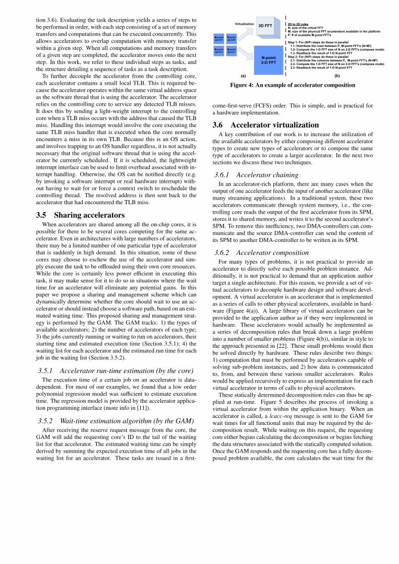
tion 3.6). Evaluating the task description yields a series of steps tobe performed in order, with each step consisting of a set of memorytransfers and computations that can be executed concurrently. Thisallows accelerators to overlap computation with memory transferwithin a given step. When all computations and memory transfersof a given step are completed, the accelerator moves onto the nextstep. In this work, we refer to these individual steps as tasks, andthe structure detailing a sequence of tasks as a task description.
To further decouple the accelerator from the controlling core,each accelerator contains a small local TLB. This is required be-cause the accelerator operates within the same virtual address spaceas the software thread that is using the accelerator. The acceleratorrelies on the controlling core to service any detected TLB misses.It does this by sending a light-weight interrupt to the controllingcore when a TLB miss occurs with the address that caused the TLBmiss. Handling this interrupt would involve the core executing thesame TLB miss handler that is executed when the core normallyencounters a miss in its own TLB. Because this is an OS action,and involves trapping to an OS handler regardless, it is not actuallynecessary that the original software thread that is using the accel-erator be currently scheduled. If it is scheduled, the lightweightinterrupt interface can be used to limit overhead associated with in-terrupt handling. Otherwise, the OS can be notified directly (e.g.by invoking a software interrupt or real hardware interrupt) with-out having to wait for or force a context switch to reschedule thecontrolling thread. The resolved address is then sent back to theaccelerator that had encountered the TLB miss.
3.5 Sharing acceleratorsWhen accelerators are shared among all the on-chip cores, it is
possible for there to be several cores competing for the same ac-celerator. Even in architectures with large numbers of accelerators,there may be a limited number of one particular type of acceleratorthat is suddenly in high demand. In this situation, some of thesecores may choose to eschew the use of the accelerator and sim-ply execute the task to be offloaded using their own core resources.While the core is certainly less power efficient in executing thistask, it may make sense for it to do so in situations where the waittime for an accelerator will eliminate any potential gains. In thispaper we propose a sharing and management scheme which candynamically determine whether the core should wait to use an ac-celerator or should instead choose a software path, based on an esti-mated waiting time. This proposed sharing and management strat-egy is performed by the GAM. The GAM tracks: 1) the types ofavailable accelerators; 2) the number of accelerators of each type;3) the jobs currently running or waiting to run on accelerators, theirstarting time and estimated execution time (Section 3.5.1); 4) thewaiting list for each accelerator and the estimated run time for eachjob in the waiting list (Section 3.5.2).
3.5.1 Accelerator run-time estimation (by the core)The execution time of a certain job on an accelerator is data-
dependent. For most of our examples, we found that a low orderpolynomial regression model was sufficient to estimate executiontime. The regression model is provided by the accelerator applica-tion programming interface (more info in [11]).
3.5.2 Wait-time estimation algorithm (by the GAM)After receiving the reserve request message from the core, the
GAM will add the requesting core’s ID to the tail of the waitinglist for that accelerator. The estimated waiting time can be simplyderived by summing the expected execution time of all jobs in thewaiting list for an accelerator. These tasks are issued in a first-
Application call
to accelerator
Runtime
Send the request to
the GAM
GAM
List of available
Acc’s + time
Which Acc’s to use?
Delay model
Decomposition
rules
Generate the steps
Execute
2D to 2D rules
N: size of the virtual FFT
M: size of the physical FFT accelerators available in the platform
P: # of available M-point FFT's
Step 1- For (N/P) steps do these in parallel
1.1- Distribute the rows between P, M-point FFT's (N<M2)
1.2- Compute the 1-D FFT size of N on 2-D FFT's (compose mode)
1.3- Readback the result of 1-D N-point FFT
Step 2- For (N/P) steps do these in parallel
2.1- Distribute the columns between P, M-point FFT's (N<M2)
2.2- Compute the 1-D FFT size of N on 2-D FFT's (compose mode)
2.3- Readback the result of 1-D N-point FFT
M-point
2D FFT
3D FFTVirtualization
N-point
2-D FFT
M-point
2D FFT
M-point
2D FFT
M-point
2D FFT
(a) (b)
!""#$#%&'(%) !""#$#%&'(%*
+"%&'",-&.) +"%&'",-&.*
/0!12(3'%($$#%) /0!12(3'%($$#%*
Figure 4: An example of accelerator composition
come-first-serve (FCFS) order. This is simple, and is practical fora hardware implementation.
3.6 Accelerator virtualizationA key contribution of our work is to increase the utilization of
the available accelerators by either composing different acceleratortypes to create new types of accelerators or to compose the sametype of accelerators to create a larger accelerator. In the next twosections we discuss these two techniques.
3.6.1 Accelerator chainingIn an accelerator-rich platform, there are many cases when the
output of one accelerator feeds the input of another accelerator (likemany streaming applications). In a traditional system, these twoaccelerators communicate through system memory, i.e., the con-trolling core reads the output of the first accelerator from its SPM,stores it to shared memory, and writes it to the second accelerator’sSPM. To remove this inefficiency, two DMA-controllers can com-municate and the source DMA-controller can send the content ofits SPM to another DMA-controller to be written in its SPM.
3.6.2 Accelerator compositionFor many types of problems, it is not practical to provide an
accelerator to directly solve each possible problem instance. Ad-ditionally, it is not practical to demand that an application authortarget a single architecture. For this reason, we provide a set of vir-tual accelerators to decouple hardware design and software devel-opment. A virtual accelerator is an accelerator that is implementedas a series of calls to other physical accelerators, available in hard-ware (Figure 4(a)). A large library of virtual accelerators can beprovided to the application author as if they were implemented inhardware. These accelerators would actually be implemented asa series of decomposition rules that break down a large probleminto a number of smaller problems (Figure 4(b)), similar in style tothe approach presented in [22]. These small problems would thenbe solved directly by hardware. These rules describe two things:1) computation that must be performed by accelerators capable ofsolving sub-problem instances, and 2) how data is communicatedto, from, and between these various smaller accelerators. Ruleswould be applied recursively to express an implementation for eachvirtual accelerator in terms of calls to physical accelerators.
These statically determined decomposition rules can thus be ap-plied at run-time. Figure 5 describes the process of invoking avirtual accelerator from within the application binary. When anaccelerator is called, a lcacc-req message is sent to the GAM forwait times for all functional units that may be required by the de-composition result. While waiting on this request, the requestingcore either begins calculating the decomposition or begins fetchingthe data structures associated with the statically computed solution.Once the GAM responds and the requesting core has a fully decom-posed problem available, the core calculates the wait time for the

0
50
100
150
200
250
300
350
400
1 2 4 8 16
Spe
ed
up
(X
)
Configuration (N cores, N threads, N accelerators)
Performance Improvement Over SW-only
Registration Deblur Denoise Segmentation
Figure 6: MI - Speedup over SW-only
0
50
100
150
200
250
300
350
1 2 4 8 16
Spe
ed
up
(X
)
Configuration (N cores, N threads, N accelerators)
Performance Improvement Over OS+Acc
Registration Deblur Denoise Segmentation
Figure 7: MI - Speedup over OS+Acc
0
100
200
300
400
500
600
700
1 2 4 8 16
Ene
rgy
Gai
n (
X)
Configuration (N cores, N threads, N accelerators)
Energy Gain Over SW-only
Registration Deblur Denoise Segmentation
Figure 8: MI - Energy gain over SW-only
0
10
20
30
40
50
60
70
1 2 4 8 16
Ene
rgy
Gai
n (
X)
Configuration (N cores, N threads, N accelerators)
Energy Gain Over OS+Acc
Registration Deblur Denoise Segmentation
Figure 9: MI - Energy gain over OS+Acc
0
10
20
30
40
50
60
1 2 4 8
Spe
ed
up
(X
)
Configuration (N cores, N threads, N accelerators)
Performance Improvement Over SW-only
EKF-SLAM IDSI LPCIP SURF
Figure 10: VN - Speedup over SW-only
0
2
4
6
8
10
12
14
16
18
1 2 4 8
Spe
ed
up
(X
)
Configuration (N cores, N threads, N accelerators)
Performance Improvement Over OS+Acc
EKF-SLAM IDSI LPCIP SURF
Figure 11: VN - Speedup over OS+Acc
! !
!""#$#%&'(%)*+,("&'-(+
!..$-"&'-(+)"&$$/)&+)&""#$#%&'(%
0#"(1.(/#)23&$"4$&'#)0#$&5
6#74#/')8&-')9-1#/):%(1);!<
!"#=-/')(:)!"">/)2)8&-')9-1#/
0#"-?#)@A&')!"">/)'()4/#
6#/#%,#)!"">/)2)BC#"4'#)D6)'&E#)/(:'@&%#).&'A
Figure 5: Accelerator composition steps
entire computation. It does this by adding the delay calculated withthe use of the regression model to the largest of the delays providedby GAM. The core then executes a series of lcacc-rsv instructionsfor each required accelerator, specifying the wait time for the entireoperation as the estimated duration of use of each accelerator re-served. GAM will not assign any accelerators until it can assign allaccelerators requested. The core releases accelerators in the sameway as it normally would. With these mechanisms, an applicationauthor can use a simple API to invoke virtual accelerators, and ahardware developer can implement accelerators based on need andavailable resources.
We will show more details on programming interface in ARCin Supplemental Section 8.1. More info on accelerator extractionmethodology can be found in [11].
4. EXPERIMENTAL RESULTSTo illustrate the effectiveness of our ARC platform, we evalu-
ate a number of compute intensive benchmarks, primarily from themedical imaging(MI) and computer vision and navigation(VN) do-mains. More information on our benchmark can be found in [11]and Supplemental Section 8.2.2. Our experiments were conductedusing a heavily modified version of the Simics and GEMS [19] [20]simulation platform. More information about our simulation plat-form can be found in Supplemental Section 8.2. Additional exper-imental results not presented here can also be found in [11].
We used the following schemes for ARC evaluation:
• Original benchmark (SW-only): The baseline for the ex-periments is the execution of these multithreaded benchmarkson a multiprocessor (one thread per processor).• Accelerators + OS management (OS+Acc): This is a sys-
tem which has accelerators managed by OS drivers.
• Accelerators + HW management (ARC): This is a systemwhich features all enhancements discussed thus far, includ-ing hardware resource arbitration managed by the GAM.
We show the simulation configuration using Cc-Tt-Aa-Dd mnemonic.Here "C" is the number of cores, "T" is the number of threads, "A"is the number of replicates of each accelerator needed by a bench-mark, and "D" is data size. For example, a benchmark featuring 4cores, 2 threads, 1 replicate of each accelerator, and an argumentthat is 64-cubes of data would be described as 4c-2t-1a-64d. ForMI benchmarks since data is cubic in form, "D" shows a cube ofD × D × D data elements for each argument. For VN benchmarksdata is linear, thus "D" shows the absolute data size. Next the re-sults for baseline speedup and energy improvement are discussed.
4.1 Speedup and energy improvementsFigures 6, 10, 8, and 12 shows the speedup and energy gain re-
sult for the ARC base configuration (Nc-Nt-Na) compared to run-ning the software-only version of the benchmark on the same num-ber of processors, threads, and data size. The highest speedup isfor Registration (485X for 1c-1t-1a-32d case) and the lowest is forEKF-SLAM (13X for 16p-16t-16a case). The best energy gainis for registration with 641X improvement. On average we get241X energy improvement over all the benchmarks and configura-tion. VN benchmarks are shown benefiting less from accelerationas compared to MI benchmarks due largely to data sizes selected.A study of the impact of data size on accelerator efficiency can befound in [11].
We observe a reduction in speedup as we increase the number ofcores and threads. This reduction is attributed to several sources.First, we measure the time from the start of all threads, to the endof the last thread, thus the results shown are the measured timeof the longest running thread. Adding more threads increases thelikelihood of observing normal fluctuations in run time. Lastly,while we increase the number of cores and accelerators, we do notcorrespondingly increase network resources, memory bandwidth,or cache capacity. As a result, increasing the number of coresand threads resulted in additional contention for communicationand memory resources. This impacted accelerated cases more thansoftware-only cases because, while the same amount of data is ac-cessed, the accelerated cases access this data over a much shortertime period.
Figures 7 and 11 show the speedup gain ARC achieves com-

0
20
40
60
80
100
120
140
160
180
200
1 2 4 8
Ene
rgy
Gai
n (
X)
Configuration (N cores, N threads, N accelerators)
Energy Gain Over SW-only
EKF-SLAM IDSI LPCIP SURF
Figure 12: VN - Energy gainover SW-only
0
2
4
6
8
10
12
14
16
18
20
1 2 4 8
Ene
rgy
Gai
n (
X)
Configuration (N cores, N threads, N accelerators)
Energy Gain Over OS+Acc
EKF-SLAM IDSI LPCIP SURF
Figure 13: VN - Energy gainover OS+Acc
0
0.5
1
1.5
2
2.5
3
0 8 16 24 32 40 48 56 64 72
Gain (X
)
Data size
LW-‐Interrupt gain
RegistraAon
Deblur
Denoise
SegmentaAon
Figure 14: Benefit of using lightweight interrupt
0
2
4
6
8
10
12
14
16
1 x 2-DFFT 2 x 2-DFFT 8 x 2-D FFT
Normalized Speedup to FFTW3
3D FFT Virtualization
2D FFT Virtualization
Figure 15: FFT virtualization(2D and 3D)
pared to the OS+Acc. Here, for larger base configurations we seean increase speedup compare to OS managed systems. The reasonsfor this are: 1) by increasing number of threads and processors,the OS management overhead (thread context switching, TLB ser-vices, ...) increases, and 2) for larger configurations, the numberof interrupts are also increasing, which makes our system performbetter due to the use of light-weight interrupt in the place of the OSinterrupts. Figures 9 and 13 also show the energy improvement ofARC over the OS+Acc case. Here by making configurations larger,we see a better energy gain over OS+Acc system. Again registra-tion performs best with 63X. On average we get 17X energy gainover OS+Acc case.
4.2 Accelerator virtualization resultsFigure 15 shows the result of virtualizing a 512x512 2D FFT and
a 128x128x8 3D FFT on multiple 128x128 2D FFTs. The SW caseis compared to having 1, 2, and 8 copies of 128x128 2D acceleratoron the chip (8 FFT is based on assigning a maximum 5% of the chiparea to FFT). The SW case is the result of running FFTW3 [12]. Inthe best case for 3D-FFT we obtained 14.4X speedup and for 2D-FFT we obtained 8.4X speedup.
4.3 Light-weight interrupt benefitTo measure the benefit of light-weight interrupts, we examined a
platform lacking light-weight interrupts to compare our ARC plat-form against a system that relies instead on OS handling of inter-rupts. Figure 14 shows the speedup measured over a platform lack-ing light-weight interrupts. ARC is up to 2.5X faster than an other-wise identical system that lacks light-weight interrupts. The largerthe data size, the more interrupts are generated, so the benefits ofARC increases as the data size grows.
4.4 Accelerator sharing resultsRun-time estimation was calculated using a simple regression
model based on profiled runs. Additional details regarding this re-gression model can be found in [11]. Wait-time estimation wasbased on the accumulated run-time estimates. Our results showsthat the estimated error ranges from < 1% to 6% of execution timeson accelerators, which is sufficiently predictable for this to be avery practical approach.
5. CONCLUSION AND FUTURE WORKWe have discussed hardware architectural support for accelerator-
rich CMPs. This was motivated by our belief that future supercom-puters, especially green supercomputers, will improve their perfor-mance and power efficiency through extensive use of accelerators.First, we presented a hardware resource management scheme forsharing of accelerators and arbitration of multiple requesting cores.Second, we presented a mechanism that allows us to efficientlycompose a larger virtual accelerator out of multiple smaller acceler-ators. Our results showed large performance and energy efficiencyimprovement over a software implementation, and also using OS-based accelerator management, with minimal hardware overhead
6. ACKNOWLEDGEMENTSThis research is partially supported by the Center for Domain-
Specific Computing (CDSC) funded by the NSF Expedition in Com-puting Award CCF-0926127, GSRC under contract 2009-TJ-1984and NSF Graduate Research Fellowship Grant # DGE-0707424.
7. REFERENCES[1] Convey computer. http://conveycomputer.com/.[2] ITRS 2007 system drivers. http://www.itrs.net/.[3] Nallatech FSB - development systems. http://www.nallatech.com/Intel-Xeon-FSB-Socket-Fillers/fsb-development-systems.html.
[4] D. Bouris et al. Fast and efficient FPGA-based feature detection employing theSURF algorithm. FCCM ’10, pages 3–10.
[5] A. Bui et al. Platform characterization for domain-specific computing. InASPDAC, 2012.
[6] N. Clark, , et al. VEAL: Virtualized execution accelerator for loops. ISCA ’08,pages 389–400.
[7] J. Cong et al. FPGA-based hardware acceleration of lithographic aerial imagesimulation. ACM Trans. Reconf. Technol. Syst., pages 1–29, 2009.
[8] J. Cong et al. Accelerating vision and navigation applications on a customizableplatform. In ASAP, 2011.
[9] J. Cong et al. AXR-CMP: Architecture support in accelerator-rich CMPs. 2ndWorkshop on SoC Architecture, Accelerators and Workloads, February 2011.
[10] J. Cong et al. High-level synthesis for FPGAs: From prototyping todeployment. Computer-Aided Design of Integrated Circuits and Systems, IEEETransactions on, 30(4):473 –491, April 2011.
[11] J. Cong, M. A. Ghodrat, M. Gill, B. Grigorian, and G. Reinman. UCLAcomputer science department technical report #120008.
[12] M. Frigo et al. The design and implementation of FFTW3. Proc. of the IEEE,93(2):216–231, 2005.
[13] P. Garcia et al. Kernel sharing on reconfigurable multiprocessor systems. FPT2008, pages 225 –232.
[14] J. Hauser et al. Garp: a mips processor with a reconfigurable coprocessor.FCCM’97, pages 12 –21.
[15] W. Jiang et al. Large-scale wire-speed packet classification on FPGAs. FPGA’09, pages 219–228.
[16] C. Johnson et al. A wire-speed powerTMprocessor: 2.3ghz 45nm soi with 16cores and 64 threads. ISSCC’10, pages 104 –105.
[17] T. Johnson et al. An 8-core, 64-thread, 64-bit power efficient sparc soc(niagara2). ISPD ’07, pages 2–2.
[18] S. Li et al. McPAT: an integrated power, area, and timing modeling frameworkfor multicore and manycore architectures. MICRO 42, 2009.
[19] P. S. Magnusson et al. Simics: A full system simulation platform. Computer,35:50–58, 2002.
[20] M. M. K. Martin et al. Multifacet’s general execution-driven multiprocessorsimulator toolset. SIGARCH Comput. Archit. News, 33, 2005.
[21] H. Park et al. Polymorphic pipeline array:a flexible multicore accelerator withvirtualized execution for mobile multimedia application. MICRO, 2009.
[22] M. Puschel et al. Spiral: Code generation for dsp transforms. Proc. of the IEEE,(2):232 –275, 2005.
[23] A. Ramirez et al. The SARC architecture. Micro, IEEE, 30(5):16 –29, Sep 2010.[24] P. Schaumont et al. Domain-specific codesign for embedded security.
Computer, 36:68–74, 2003.[25] L. Seiler et al. Larrabee: A many-core x86 arch. for visual computing. IEEE
Micro, 29:10–21, 2009.[26] P. Stillwell et al. HiPPAI: High performance portable accelerator interface for
SoCs. HiPC 2009.[27] N. Sun et al. Using the cryptographic accelerators in the ultrasparc t1 and t2
processors. Sun BluePrints Online, 2007.[28] G. Venkatesh et al. Conservation cores: reducing the energy of mature
computations. ASPLOS ’10.[29] P. H. Wang et al. EXOCHI: architecture and programming environment for a
heterogeneous multi-core multithreaded system. PLDI ’07.
! !
!"#"$%&''($%#"$)*+$*#,-
.-*#/$%#((-01$*2341$5,#,-06#,73""$*7!'3%$8$%09(#"8),/:9,);$43405-
<#,4=#,30.3;3()'3,>
.3;3()'/3*"0?()=
@A3%B"3409,)7,#/
&''($%#"$)*!)B,%30C)43
&%%3(3,#"),<3#43,0?$(3
C)/'$(3,
Figure 16: ARC development flow
8. SUPPLEMENTAL
8.1 Programming interface to ARCThe Application Programming Interface (API) involved in using
accelerators is presented in Figure 16. For each type of accelerator,one dynamic linked library (DLL) is provided. This DLL is specificto a target platform, and provides a mapping from accelerator callsto actual invocations of physical accelerators. Calls to acceleratorshave their implementations dynamically linked to application code.
8.2 EVALUATION METHODOLOGY
8.2.1 Simulation tool-chainIn order to make the exploration of this topic practical, a num-
ber of supporting tools were created. These tools simplified theauthoring of programs that used accelerators, and automated theprocess of implementing our chosen accelerators in our simulatorframework. These tools were used in place of hand-written imple-mentations and hand-adapted benchmarks to allow us to simulatesystems that would have been prohibitively complex to manuallyauthor, such as those that utilized many accelerators or featuredcomplicated inter-accelerator communication. Additionally, we be-lieve that this is representative of what will be done in the develop-ment of future accelerator exploiting libraries, to simplify the job ofprogrammers who would use these libraries without compromisingany of the capabilities of these accelerators.
With this toolchain, generation of accelerators is only a matterof identifying a function in an application’s source code to acceler-ate. We have automated the process of extracting these functions,compiling these modules into VHDL, and synthesizing these mod-ules to extract timing and energy information. This process yields amodule that plugs into our cycle-accurate simulation infrastructureto model this hardware unit, and coordinates the execution of thisselected function in a pipelined fashion.
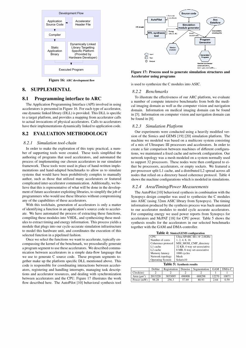
Once we select the functions we want to accelerate, typically en-compassing the kernel of the benchmark, we procedurally generatea program segment to use these accelerators. We described commu-nication between accelerators in a simple data-flow language thatwe use to generate C source code. These program segments to-gether make up the platform specific DLL mentioned above. Thiscode is responsible for coordinating interactions between acceler-ators, registering and handling interrupts, managing task descrip-tions and accelerator resources, and dealing with synchronizationbetween accelerators and the CPU. Figure 17 illustrates the workflow described here. The AutoPilot [10] behavioral synthesis tool
Figure 17: Process used to generate simulation structures andAccelerator using programs
is used to synthesize the C modules into ASIC.
8.2.2 BenchmarksTo illustrate the effectiveness of our ARC platform, we evaluate
a number of compute intensive benchmarks from both the medi-cal imaging domain as well as the computer vision and navigationdomain. Information on medical imaging domain can be foundin [5]. Information on computer vision and navigation domain canbe found in [8].
8.2.3 Simulation PlatformOur experiments were conducted using a heavily modified ver-
sion of the Simics and GEMS [19] [20] simulation platform. Themachine we modeled was based on a multicore system consistingof a mix of Ultrasparc III processors and accelerators. In order tocreate a fair comparison between machines of different configura-tions, we maintained a fixed cache and network configuration. Ournetwork topology was a mesh modeled on a system normally usedto support 32 processors. These nodes were then configured to ei-ther be processors, accelerators, or empty sockets. We featured aper-processor split L1 cache, and a distributed L2 spread across allnodes that relied on a directory based coherence protocol. Table 4shows the machine configurations which is modeled in simulations.
8.2.4 Area/Timing/Power MeasurementsThe AutoPilot [10] behavioral synthesis in combination with the
Synopsys design compiler was used to synthesize the C modulesinto ASIC (using 32nm ASIC library from Synopsys). The timinginformation produced by the synthesis process was back-annotatedto our accelerator modules to model cycle accurate accelerators.For computing energy we used power reports from Synopsys foraccelerators and McPAT [18] for CPU power. Table 5 shows thesynthesis results for the accelerators in our selected benchmarkstogether with the GAM and DMA-controller.
Table 4: Simics/GEMS configurationCPU Ultra-SPARC III-i @ 2.0GHzNumber of cores 1, 2, 4, 8, 16Coherence protocol MSI_MOSI_CMP_directoryL1 cache 32 KB, 4 way set-associativeL2 cache 8 MB, 8-way set-associativeMemory latency 1000 cyclesNetwork topology MeshOperating System Solaris10
Table 5: Synthesis results
Deblur Registration Denoise Segmentation GAM DMA-CClock(ns) 2 2 2 2 1 1Area (µm2) 2013228 3853095 496908 688298 12270 10071Power (mW) 98.28 256.3 57.69 80.93 2.64 0.59