architecture portfolio
DESCRIPTION
Architecture portfolio 2006-2011TRANSCRIPT

ARCHITECTURE PORTFOLIO
MICHAEL W.T. CHAN2007-2011

Michael ChanMasters of Architecture Professional University of AucklandSchool of ArchitectureNew Zealand
Address401 East 34th Street, Apt. S26CNew York. 10016
917-254-0812 [email protected] http://issuu.com/michaelwtchan/docs/portfolio

Contents
Salvation Hut architecture for the extreme alpine
Dark Light water researh institute
Z-Energy (prof.) rebrand of Shell to Z-energy


Alpinists who travel beyond the chairlifts and groomed trails need a point of refuge from the harsh weather. With low altitude resorts being affected by the warming climate, more mountain enthusiasts are venturing beyond the lifts to find better snow with less crowds. The next generation of ski resorts will need to be built higher in some of the most extreme conditions and thus endure greater forces. This project has been an attempt to provide a solution for building an autonomous salvation hut in the extreme alpine climate.
The unpredictability, isolation and climatic conditions were the most significant challenges the building faces. Logistical issues of transporting materials were explored. By implementing unconventional methods of transporting materials, costs during construction will be reduced significantly.
The result is a flexible building that has hydraulic columns that allow the building to change with the landscape and an exterior retractable shell that can open or closed according to weather. These flexible components accommodate the changes between the different site conditions set in different seasons. This flexibility is perfect for such an unpredictable site. Without a public source of services, the building needed to be autonomous. Energy and water harvesting was explored to maximize the comfort and urbanity of the building.
Mount Ruapehu Salvation Hut: Solutions in Designing for the Alpine Extreme


Above:Site plan
Left Page top:Site photo of Mt. Ruapehu summer landscape
Left Page bottom:Site photo of Mt. Ruapehu Winter landscape
Next Page:Alpine hut exterior in fullfuntion mode.
Left Page top:Alpine hut transformation to Salvation hut in its lock-down mode during harsh climatic conditions

pangolin- Regular State
Concept: PangolinThe core concept for the New Ruapehu Salvation Hut is its impressive isolation amidst a mighty and sometimes brutal landscape. In order to survive, the building must be able to adapt to the site’s conditions. The main goal of the design is to not only provide mountaineers comfort but also adapt to their needs in different climatic situations.
The architectural form is based on the concept of a pangolin’s defensive mechanism and its ability to transform when it feels threatened. It does so by curling into itself, surrounded by its overlapping armour. The project utilized the idea of being able to adjust and adapt to a regular environment and a threatened environment when suitable.

pangolin- Threatened State
The core concept for the New Ruapehu Salvation Hut is its impressive isolation amidst a mighty and sometimes brutal landscape. In order to survive, the building must be able to adapt to the site’s conditions. The main goal of the design is to not only provide mountaineers comfort but also adapt to their needs in different climatic situations.
The architectural form is based on the concept of a pangolin’s defensive mechanism and its ability to transform when it feels threatened. It does so by curling into itself, surrounded by its overlapping armour. The project utilized the idea of being able to adjust and adapt to a regular environment and a threatened environment when suitable.

Shell opened in normal conditionsRegular State

Threatened StateShell is closed to protect building from External forces.Hydraulic legs elevate building over increased snow base.

Booth operating in regular state as a dining table and storage units
Regular State

Threatened StateBooth transformed into bunkbeds in threatened state, for emergency situations


Water Diagram:(a) Capturing rain and melt water(b) Bladder tank storage unit (c) Feed pipe(d) Disinfection/filtration system(e) Heat store(f) Fresh water kitchen(g) Handwash basins(h) Showers(i) Waste Water(j) Microbiological treatment plant(k) Greywater

Wind TunnelWind tunnel testing on simple volumes, using smoke to visually show flow and turbulence created upon surfaces.
Electricity Diagram:(a) Obtaining power from photovoltaic system(b) Batteries(c) Appliances(d) Cogeneration plant for back up supply of power, heat, hydraulic pumps and shell operation(e) Heat store(f) Shell operation(g) Hydraulic pumps


1 2
43
65
Transportation and Construction MethodsConstruction in extreme conditions calls for drastic methods. When constructing in the high mountains every possible way is explored to make the build as efficient and as inexpensive as possible. Using multiple methods of transporting construction members will reduce the amount of helicopter usage which reduces costs significantly.

0
1
-1
-2
2
Above:Exploded Axonometric

12
34 5
7
8
6
9
Roof Detail(1) Double-standing seam ‘Tecu Patina’ Copper sheeting (4mm), 30mm (2) Marine plywood boarding, 27mm(3) Back Ventilation, batterns, 30mm(4) Facade building membrane Monarflex with nail sealing tape, 0.5mm(5) Marine plywood boarding, 30mm(6) Aerogel insulation for thermal bridging, Thermablok, 5mm(7) Phenolic foam insulation, 2 layers, 300mm(8) Moisture resistant plasterboard, 13mm(9) Insulated solar glass with Aerogel between layers, 60mm

12
34 5
7
8
6
9


Water ResearchInstitute
Dark Light:
Definition, Phenomenological Architecture:
Lake George Scott is a small man-made reservoir located downstream, about 2 kilometres from the New Zealand land mark Lake Tekapo.
An intake tunnel running through a small hill above Tekapo village supplies the water to the Tekapo A power station. This Project located by Lake George Scott acts as water research facility that is an extension to the existing Hydro-power station. A small portion of the water running through the intake tunnel to the power station will be diverted to the facility for lab tests and research before entering the canal and back into the eco-system.
The public realms of the building becomes a museum for water, where visitors can learn and experience the studies of water tested in the facility. This is the focal point of the project. Water is used as architectural materiality throughout the project to enchance the atmoshpere , experience and its phenominological effects. Visitors wandering through the building is immersed with the different effects of water and its different states. The building is choreographed with light, shadows and reflections created by water which sets different paces at different parts of the building.
“In phenomenology, the environment is concretely defined as "the place," and the things which occur there "take place." The place is not so simple as the locality, but consists of concrete things which have material substance, shape, texture, color, shadow and light, and together coalesce to form the environment’s character, or atmosphere”

Top Left:Lighting study model
Top Right:Water with lighting study model
Above:Lake George Scott Site Photo
Right:Site Plan


Top Left:Lighting study model
Top Right:Water with lighting study model
Above:Lake George Scott Site Photo


b
b
GF
1F
Plan
Cross-Section
bb

c
c
cc


Section

1 2


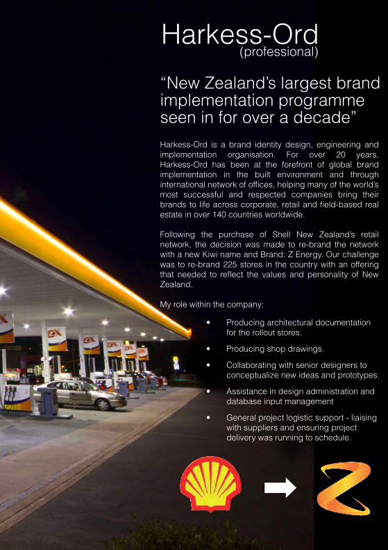
Harkess-Ord (professional)
“New Zealand’s largest brand implementation programme seen in for over a decade”Harkess-Ord is a brand identity design, engineering and implementation organisation. For over 20 years, Harkess-Ord has been at the forefront of global brand implementation in the built environment and through international network of offices, helping many of the world’s most successful and respected companies bring their brands to life across corporate, retail and field-based real estate in over 140 countries worldwide.
Following the purchase of Shell New Zealand’s retail network, the decision was made to re-brand the network with a new Kiwi name and Brand: Z Energy. Our challenge was to re-brand 225 stores in the country with an offering that needed to reflect the values and personality of New Zealand.
My role within the company:
• Producing architectural documentation for the rollout stores.
• Producing shop drawings.
• Collaborating with senior designers to conceptualize new ideas and prototypes.
• Assistance in design administration and database input management
• General project logistic support - liaising with suppliers and ensuring project delivery was running to schedule.

74
Front Elevation Side Elevation - Portal Frame Side Elevation - Portal Cladding
Portal Spreader Bar
Set out, level then bolt Portal Uprightsinto position
Position SignBackground to ensureFixing engage with Portal Frame.
100 x 50 Timber Stud to
Fasten Spreader Barto Sign Frame withØ 6mm TEKS
Hook face into BackingFrame then secure with8 x CSK Fixings
Power feed to run through Portal Uprightinto side of SignBackground
4
Cutout in Uprights to
shopfront portal
rear corner angle afterall external panels are
5 Fasten Sign Background toUprights using 8 x Ø 6mmTEKS
3
5
2
1
B
A
Slide Cladding Panels into external Upright Facades. Then screw capping angleinto place at top and rear
back of angle of Uprights
100 x 50 Timber Stud
Fasten Timber Stud to existing Steel Studs
20 mm
Section Detail A - Entry Portal Sign
Detail B - Portal to ground connection
Supplied Square Washer
Ø 10 mm min True Bolt
Timber Block
Plastic Leveling Packer
Timber Packerwidth chosen byInstaller to suitSite
Copyright © 2011 This document is the property of Harkess-Ord and must not be used, reproduced or disclosed to any persons without written consent from Harkess-Ord
Z ENERGY
IT IS THE INSTALLERS RESPONSIBILITY TO ENSURE ALL PRODUCT FIXINGS, FOUNDATIONS AND FOOTINGS WILL WITHSTAND WIND AND OTHER APPLICABLE STRUCTURAL LOADINGS IN ACCORDANCE WITH THE REGULATIONS, CODES & STANDARDS OF THE LOCAL INSTALLATION LOCATION.INSTALLATION, FIXINGS & FIXING METHOD MUST BE SUFFICIENT TO MEET THE ANTICIPATED STRUCTURAL LOADS APPROPRIATE TO THE SITE SPECIFIC SURFACE TO WHICH THE COMPLETED SIGN IS TOBE MOUNTED.ALL ELECTRICAL COMPONENTS, WIRING & SWITCH GEAR MUST BE APPROPRIATE FOR THE ENVIRONMENT IN WHICH THE COMPLETED PRODUCT IS TO BE INSTALLED AND COMPLY WITH ALLAPPROPRIATE CODES AND REGULATIONS OF THAT REGION.
IMPORTANTINSTALLATION GUIDELINE INSTRUCTION SHEET NAME DATEVERSION
Level 5, Koorb House 9 Hargreaves StSt Marys Bay, Aucklacnd, New ZealandPhone: 09 3020751 Fax: 09 302 0761
Shop Entrance Sign Illuminated Light Box - Tier 1GEL-ST-1-SESI-3820x945-GIS
V03 14.11.2011
Address401 East 34th Street, Apt. S26CNew York. 10016
917-254-0812 [email protected] http://issuu.com/michaelwtchan/docs/portfolio
Thank You