architecture, engineering, and construction division cad standard cad-std 2009-v03.pdf ·...
TRANSCRIPT

Architecture, Engineering, and Construction Division
CAD Standard
Release Date: 28 April 2009 All previous versions of this document are obsolete.
A copy of this document is available for download on the AEC website. http://aec.ldschurch.org/aec/
Consulting architect, engineers and landscape architects may request a copy from
Nancy Black (email: [email protected]) Phone: 801-240-2431
Contact Nate Erickson in AEC with questions or suggestions for improvement.
Published by
The Church of Jesus Christ of Latter-day Saints

Table of Contents Introduction ....................................................................................................... 1
Purpose ........................................................................................................................ 1 Scope ........................................................................................................................... 1 CAD System ................................................................................................................ 1
File Type & Naming Conventions ..................................................................... 1
Project File Types ........................................................................................................ 1 Naming Model Files ..................................................................................................... 2 Naming Sheet Files ...................................................................................................... 3
Sheet Organization ............................................................................................ 5
Standard Sheet Sizes .................................................................................................. 5 Sheet Layout ................................................................................................................ 5
Drawing Setup ................................................................................................... 5
Template Drawings ...................................................................................................... 5 Use of the Layout Tabs ................................................................................................ 6
Layer Naming .................................................................................................... 6
Objectives .................................................................................................................... 6 Layer Guidelines .......................................................................................................... 6
Drawing Standards ............................................................................................ 8
Annotation .................................................................................................................... 8 Line Types ................................................................................................................. 10 Hatching ..................................................................................................................... 10 Dimensions ................................................................................................................ 10 Drawing Orientation ................................................................................................... 11 Building Grid System.................................................................................................. 11 Abbreviations ............................................................................................................. 12
Tables ............................................................................................................... 14
Layer Names .............................................................................................................. 14
ii

Introduction Purpose
The purpose of this document is to provide consultant architects, engineers and landscape architects with the standard for project and standard plan CAD drawings.
This document is based on and utilizes the standards established by the National CAD Standard (NCS) 2008 version as created by the National Institute of Building Sciences (NIBS), American Institute of Architects (AIA), Construction Specifications Institute (CSI) and the Tri-Service CADD/GIS Technology Center and the U.S. Coast Guard. The AEC CAD Standards represent best practices for LDS Church meetinghouse, seminary and institute and Welfare Services Department projects. This standard is to be used in all cases regardless of office standard or personal preferences.
Scope This standard is a guide for developing architectural, engineering, and landscape CAD drawings for project and standard plan documents. This document is intended as a CAD standard reference and not as a CAD training manual.
CAD System The CAD software used as a basis for this Standard is: AutoCAD 2009 with AutoCAD Architecture (ACA) 2009 File Type & Naming Conventions
Project File Types Model
• “A building model is an electronic representation of a building. Elements graphically representing the building or site should always be created at their ‘real world’ size in their ‘real world units’… These models may be 2D or 3D, but they all must be accurate, complete and in conformance to emerging industry standards in regards to layer/level usage and symbology.” (NCS pg UDS-01.17)
• The model files are references in sheet files for use in printing and also by other model files.
• Model files are created in model space. • Model files do not have title blocks or any information which appears in paper
space. • Because these model files are referenced in other files, model naming is
important. (See Naming Model Files below) • Items to include in a model file:
o Information to share among disciplines and multiple sheets For example: Walls, windows, doors and etc.
o Dimensions o Items referenced in automatic schedules
1

For example: door tags, window tags, room tags
Sheet • Drawing sheets are the finished product of CAD file sets representing scaled
drawings that are actually printed (or plotted) to paper or other drawing media. • Sheet files are plotted at full scale (1=1). • These files also contain the title block and project specific information located in
Paper Space. • Sheet files often contain cross-references (xref) to model files.
Model files vs. Sheet files • Distinguishing between models and sheets is useful for several reasons:
o CAD drawings are often developed during design, long before the organization and layout of the construction documents are known.
o Early design models can be developed without concern for the specific layout of the individual construction documents that follow.
o Sheets representing construction documents or other documents can be developed at a later stage, when the organization and content of the set are better understood.
o More personnel can work on a project at the same time. o Coordination between disciplines is improved. o Duplication of efforts is eliminated.
Naming Model Files Naming Convention
• Identify model files that are referenced into sheet files using the following format: XXAA
Where: XX Project prefix (assigned by AEC) AA Discipline designator (see descriptions listed below)
2
Description • Project Prefix - XX
o Each project is assigned a two-letter or longer prefix established by AEC. Use this prefix to name each model file associated with a project. Example: HE for Heritage meetinghouse standard plan
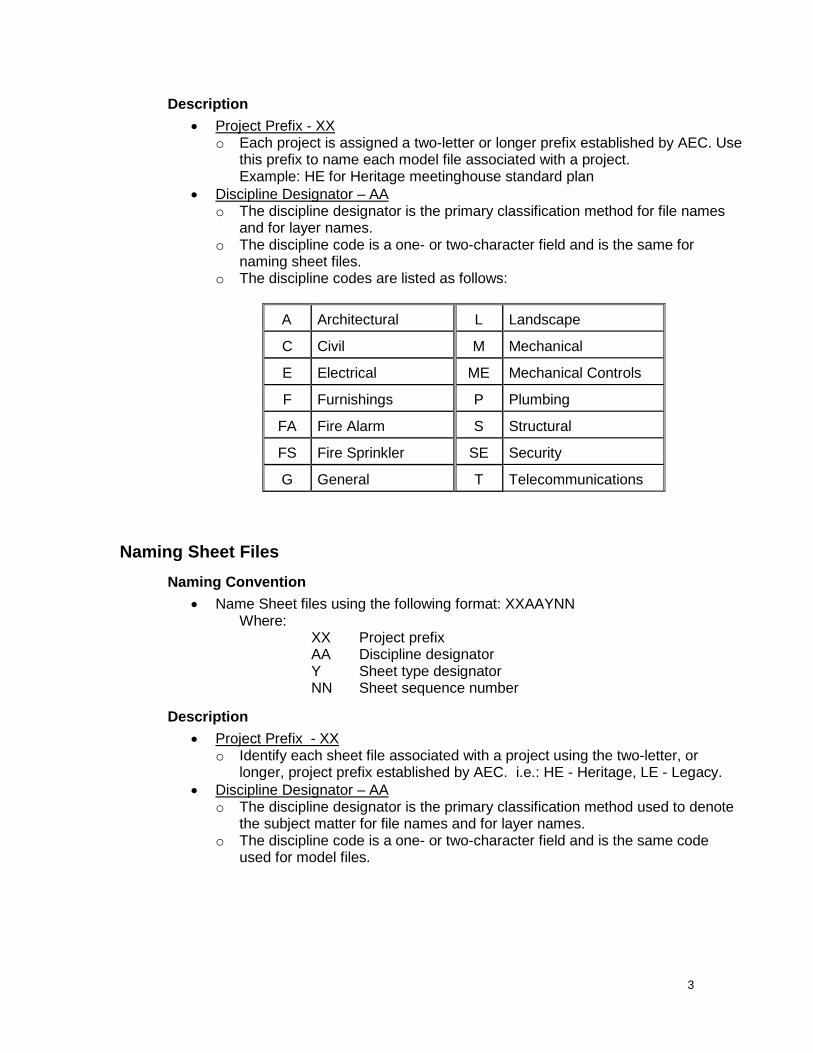
• Discipline Designator – AA o The discipline designator is the primary classification method for file names
and for layer names. o The discipline code is a one- or two-character field and is the same for
naming sheet files. o The discipline codes are listed as follows:
A Architectural L Landscape
C Civil M Mechanical
E Electrical ME Mechanical Controls
F Furnishings P Plumbing
FA Fire Alarm S Structural
FS Fire Sprinkler SE Security
G General T Telecommunications
Naming Sheet Files Naming Convention
• Name Sheet files using the following format: XXAAYNN Where:
XX Project prefix AA Discipline designator Y Sheet type designator NN Sheet sequence number
Description • Project Prefix - XX
o Identify each sheet file associated with a project using the two-letter, or longer, project prefix established by AEC. i.e.: HE - Heritage, LE - Legacy.
• Discipline Designator – AA o The discipline designator is the primary classification method used to denote
the subject matter for file names and for layer names. o The discipline code is a one- or two-character field and is the same code
used for model files.
3

o The discipline codes are listed in the following table:
A Architectural L Landscape
C Civil M Mechanical
E Electrical ME Mechanical Controls
F Furnishings P Plumbing
FA Fire Alarm S Structural
FS Fire Sprinkler SE Security
G General T Telecommunications
• Sheet Type Designators – Y o A single numerical character identifies the sheet type. o All sheet types may not apply to all discipline designators. o It may not be necessary to use all sheet types for a project or within a
discipline.
No. Type Description 0 General Symbols legends, notes, etc. 1 Plans Horizontal views 2 Elevations Vertical views, exterior elevations 3 Sections Sectional views, wall sections 4 Enlarged Plans Enlarged plans, interior elevations, stair sections 5 Details 6 Schedules 7 User Defined For types that do not fall in other categories 8 User Defined For types that do not fall in other categories 9 3D Representations Isometrics, perspectives, photographs
o The use of sheet type designators does not preclude combining different
drawing types on the same sheet for simplicity.
• Sheet Sequence Number – NN o A two-digit sheet sequence number identifies each sheet in a series of the
same discipline and sheet type. o Number sheets from 01 through 99. Do not use sheet number 00. Do not use
a lower case letter at the end of the sheet number. o To permit insertion of future sheets, you do not need to number sheets
sequentially. Examples: HTA101 Heritage Traditional, architectural, floor plan, sheet 01 HNS502 Heritage New England, structural, detail, sheet 02
4
Sheet Organization Standard Sheet Sizes
• AEC uses five sizes of sheets for construction documents ANSI D 22 x 34 ARCH D 24 x 36 This is the preferred size sheet for projects. ARCH 30 30 x 42 Used for large projects and to avoid break lines in
the plans, elevations and sections. 12 x 18 12 x 18 Used to make half-size document sets. 8 ½ X 11 8 ½ x 11 Used as required.
Sheet Layout Detail and Elevation Sheets
• Lay out details and elevations in a modular format. • Identify details with a letter designation. • Start details with ‘A’ in the upper left-hand corner of the sheet and continue
across the sheet, from left to right, in sequential order. If another row of details is required, start it below the first row and letter the new row as described above.
Use of ‘I’ and ‘O’ • Do not use the letters ‘I’ and ‘O’ when identifying detail locations on a sheet. • These letters are easily confused with the numbers ‘1’ and ‘0’. • Do not use ‘I’ and ‘O’ as building grid system identifiers.
Plan Sheets • All plans, including enlarged plans, are to be identified by a number. • Enlarged plans will be included on the same sheet as the room’s interior
elevations whenever possible.
Working with Multiple Scales • Use the same scale for all drawings on a single sheet where possible. • Sheets may sometimes require different scale drawings on the same sheet. • In all cases, show the scale for each drawing or view on a sheet. • When necessary, you can set different scales for different view ports. • When setting various scales for view ports, place all text in the view port (model
space). • All view ports shall be locked.
Drawing Setup
Template Drawings • Template or prototype drawings are used to begin all new drawings.
5

• The Template drawings contain all the AEC standard settings including: Layers
Font Style Dimension Style
• Template files are located on the CD in the Templates folder. • There are eight AEC template files. • All templates are identified with a .dwt extension.
File Name Description PFD 11x17.dwt 11 x 17 sheet size PFD Arch B.dwt 12 x 18 sheet size PFD ANSI D.dwt 22 x 34 sheet size PFD Arch D.dwt 24 x 36 sheet size PFD Arch E.dwt 30 x 42 sheet size
Use of the Layout Tabs Number of Tabs
• Limit the number of layout tabs to two: o one for the model (Model Space) o one for the page layout (Paper Space)
Tab Names
To facilitate coordination and allow the Sheet Set Manager to work properly: • Rename the layout tabs to match the sheet number by right-clicking the desired
tab and selecting RENAME. • The layout tab should be renamed to match the sheet number. • This facilitates coordination and allows the Sheet Set Manager to work properly.
Example: A101, A501 Layer Naming
Objectives • Naming layers that follow the NCS enables multiple users of drawings to work
efficiently with a minimum of downtime. • Use intuitive layer names and group them together with like layers.
Layer Guidelines • Use alphanumeric layer names and abbreviations that are easy to remember. • This alphanumeric arrangement accommodates expansion and addition of user-
defined extensions to the layer list.
6

• There are four defined layer name data fields: o Discipline Designator o Major Group o Minor Group o Status
• The full layering system may not need to be used in all situations. • The layering system is flexible to allow project adaptations within layering system
guidelines.
Naming Convention • For a listing of approved layer naming – See Layer Names section below. • Follow this convention for naming layers:
A-MMMM-NNNN-S Where: A Discipline Designator MMMM Major Group NNNN Minor Group S Status Field (Optional)
• Discipline Designator: A o The discipline designator is the same as the discipline designator used in the
file naming conventions previously discussed. o It is a two-character field with the second character a hyphen. The defined
discipline codes are the same for layers and for file names. Example: The file LEA101.dwg might contain layers A-WALL, A-DOOR and A-CLNG.
• Major Group: MMMM
o The Major Group is a four-character field that identifies a major building system. Example: Doors, Windows, Wall, etc.
o Although major groups are logically grouped with specific discipline codes, it is possible to combine major group codes with any of the discipline codes. Example: Architectural Columns: A-Cols; Structural Columns: S-Cols
o User defined major group fields are not permitted. Example: a drawing might contain the following layers:
Layer Name Description Layer Name Description A-WALL Walls A-DOOR Doors E-LITE Light fixtures G-NOTE Text, Annotation
• Minor Group (OPTIONAL): NNNN o This is an optional, four-character field to further define the major groups. o Although minor groups are logically grouped with specific discipline codes, it
is possible to combine major group codes with any of the discipline codes.
Example: A-WALL-PART indicates architectural, new wall, and partial height. The following are examples of common modifiers that are defined for use in the minor group field:
7

Modifier Description Modifier Description IDEN Identification SYMB Symbols PATT Pattern DIMS Dimensions NOTE Notes
• Status Field (OPTIONAL): S o The status field is an optional single-character field that distinguishes the data
contained on the layer according to the work or the construction phase status. Example: The status identifies whether the work remaining is temporary, demolition or existing.
o Do not use the status field on new standard plan documents. o Examples of the defined values for this field are as follows: Modifier Description Modifier Description E Existing M Items to be moved T Temporary work D Demolition work
Drawing Standards Annotation
Font Style • All disciplines should use SIMPLEX as the standard font for all drawings. • Dimensions use a text style called SIMPDIMS that is based on the SIMPLEX font
with a narrower width. • The SIMPLEX font remains clearer and avoids confusion when the documents
are printed as half-size sets. • The font sizes and locations used are as follows:
Text notes 3/32” Detail titles 7/32” Mid size text 5/32”
8

Plotted Font Sizes
Drawing scale
Standard text Title text
Mid size text
1/16" = 1'-0" 1'-6" 3'-6" 2'-6" 3/32" = 1'-0" 1'-0" 2'-4" 1'-8" 1/8" = 1'-0" 9" 1'-9" 1'-3" 3/16" = 1'-0" 6" 1'-2" 10" 1/4" = 1'-0" 4-1/2" 10-1/2" 7-1/2" 3/8" = 1'-0" 3" 7" 5" 1/2" = 1'-0" 2-1/4" 5-1/4" 3-3/4" 3/4" = 1'-0" 1-1/2" 3-1/2" 2-1/2" 1" = 1'-0" 1-1/8" 2-5/8" 1-7/8" 1-1/2" = 1'-0" 3/4" 1-3/4" 1-1/4" 3" = 1'-0" 3/8" 7/8" 5/8" 6" = 1'-0" 3/16" 7/16" 5/16" FULL 3/32" 7/32" 5/32"
Types of Annotation • Annotation comprises text, dimensions, sheet borders, detail references and
other elements on CAD drawings that don’t represent physical aspects of a building. o Types of annotation are designated by the following layer names:
Layer Name Description G-DIMS Dimensions G-NOTE Notes G-SYMB Symbols G-TITL Drawing Titles
Location of Annotation • Annotation in Model Space: Place all annotation, including dimensions, notes,
callouts, etc., in Model Space only. o Always place dimensions in Model Space. They are linked to the
dimensioned object. • Annotation in Paper Space: Place only the title block and project information in
Paper Space. • Sheet File vs. Model Files:
o Place annotation in either the model file or in the sheet file. o Model file annotations: Include annotations that apply to the project such as dimensions, notes,
grids and symbols in the model file. Place any annotation information that will be shared between multiple
sheets in model file. Place items that read information from an object in the model file.
Example: Door numbers read information from the doors. o Sheet file annotation: Include more specific types of annotation such as drawing titles, legends,
symbols, and sheet specific notes in the sheet file.
9

• Notes o Left-justify all notes. o Locate the leader from the top front of the first line of text when the note is
located to the left of the referenced item. o Locate the leader from the bottom end of the first line of the text when the
note is located to the right of the referenced item. o Match drawing note terminology to that used in the specifications. o Do not use the @ symbol use the word “at”.
• Graphic Elements
o Place all graphic elements (walls, doors, grid, furniture, flooring, etc.) and annotation anchored to plan elements (wall, door, room tags, wall tags etc.) in Model Space and ensure they are drawn at full scale.
o Establish a scale for the drawing in Paper Space.
Line Types There are various line types used throughout a drawing. • The scaling used is different between Paper Space and Model Space. • Ensure the line type space is at 1 to ensure proper plotting and translation to
other CAD formats. • To view the line types properly in Model Space, adjust your LTSCALE according
to the scale of the drawing. Set the LTSCALE to 1 for plotting. • In the LINETYPE MANAGER, ensure that the following are set:
o Global Scale Factor 1 o Current Object Scale 1 o Use Paper Space units for scaling (the box should contain a check)
Hatching Standards
• Hatching in AutoCAD can be either associative or non-associative. • When picking the area to hatch, AutoCAD remembers the objects that bound the
area. If one of these boundaries is removed, the association is lost. At this point, the hatching becomes a block and remains in its current configuration.
Dimensions Dimension Style
• The AEC office dimension style is called AEC_ARCH_1 and is set as the default in the template files.
• All settings for the standard dimension style (color of lines, text color, height, arrowheads, appearance, etc.) are saved in the template files. Do not modify the template files.
• Ensure that dimensions are adequate and accurate. • Place all dimensions on the G-DIMS layer. • Do not override the default dimension when preparing construction documents.
10

Associative Dimensions • Use associative dimensions at all times.
o CAD programs allow us to draw precisely and accurately. o With associative dimensioning, if a wall is stretched, the dimensions change
automatically.
Standards • Format: Write all dimensions out in FEET and INCHES (1’-6”) unless the
dimension is less than 12”. • Location:
o Measure dimensions on plans from the face of studs, concrete, CMU, etc., not from the finished face of the wall, unless specifically identified. Example: 5’-0” clear from face of wall.
o Relate dimensions on elevations to an established reference plane, such as the finished floor level, a grid line, or criteria established that is appropriate to the project.
• Hierarchy: Dimension hierarchy is: (1) Overall (2) Structural grid (3) Openings & wall locations
• Precision: o Set the dimension precision to 1/32” for all drawings. o If the precision is set any higher, the dimensions round up, causing a string of
associative dimensions to total up incorrectly. o Adding up the dimensions in a string may not total up to the same
measurement as the overall dimension.
Drawing Orientation • Ideally, show the floor plan on one sheet. • Use of match lines:
o If the floor plan cannot fit on one sheet, subdivide it into convenient areas and provide match lines to reference where the floor plan continues.
o Include a key plan on all plan sheets that continues on multiple sheets. o Use match lines to signify the division between two or more areas of
continuous structure that shows on separate sheets due to sheet size limitations
o Do not place match lines on column lines, grid lines, or expansion joints. o Place match lines at the centerline of a wall or corridor. o Display match lines in the same location on both sheets containing adjacent
segments of the plan. o Jog match lines to avoid important plan elements.
• To avoid confusion, maintain a consistent plan orientation throughout the drawing set. Example: Display an enlarged plan in the same orientation as shown on the overall floor plan.
Building Grid System • Use a building grid system to indicate structural columns, load-bearing walls,
shear walls, and other structural elements on the drawings. • Use a building grid as a basis for dimensioning. • The grid system includes the following guidelines:
11

o Place designators at the top of the grid, numbered sequentially from left to right, for grid lines that run vertically on the building.
o Place designators at the right side of the grid, alphabetized sequentially from top to bottom, for grid lines that run horizontally on the building.
o To avoid confusion with the numbers 0 (zero) and 1 (one), do not use the letters O and I in the building grid.
o In some cases, you may show grid line designators at both ends of the grid line for reference purposes.
o Where additional structural support elements occur between grid lines, use a fractional designation. Example: Identify a column occurring at the mid-point between grid 2 and 3 as 2.5. If it is located between grids B and C identify it as B.5.
Abbreviations General Rules for Abbreviations:
• Only abbreviate terms with six or more letters. • Do not abbreviate terms with five letters or less. Exceptions are noted in the list
below. • Avoid using abbreviations with more than one meaning. • Do not use an abbreviation if doubt or confusion exists regarding the meaning. • Keep abbreviations to a minimum and limit them to common industry standard
abbreviations.
Approved Abbreviations Acceptable and approved abbreviations and their meaning are as follows:
12

Abbreviations Abbrev. Item Abbrev. Item Abbrev. Item
Alum Aluminum Ft/lbs Foot pounds RA Return air
BO Bottom of GA Gage REF Refrigerator
BTU/HR British thermal units per hour GALV Galvanized RCP Reflected ceiling
plan CFM Cubic feet per minute H High REQD Required
CLR Clear HSS Hollow structural section SA Supply air
CO Cleanout L Angle SST Stainless steel
CONC Concrete LL Live load SCHED Schedule
CONT Continuous LBS Pounds SECT Section
COTG Clean out top of grade LSL Laminated
strand lumber SIM Similar
CU. FT. Cubic foot LVL Laminated veneer lumber SPEC Specification
D Deep MAX Maximum SF Square foot
DL Dead load MECH Mechanical STD Standard
DIA Diameter MIN Minimum SYS System
DIV Division MISC Miscellaneous TO Top of
DWV Drain waste and vent NIC Not in contract TYP Typical
EWC Electric water cooler OA Outdoor air VERT Vertical
EA Each OC On center VEST Vestibule
ELEC Electrical OD Outside diameter VTR Vent through roof
EQUIP Equipment OPP Opposite W Wide
ETC Et cetera PLF Pounds per linear foot W/ With
EXA Exhaust air PSF Pounds per square foot W/O Without
EXT Extinguisher PSI Pounds per square inch WCO Wall cleanout
FEC Fire extinguisher cabinet PSIG PSI gage
FLEX Flexible PVC Polyvinyl chloride
FT Foot R Radius
13

Tables Layer Names
Architectural (Model) LAYER NAME DESCRIPTION COLOR PLOT LINETYPE A-Area Areas 173 No Plot Continuous A-Area-Bdry Space boundaries 140 No Plot Continuous
A-Area-Rnam Room tags Yellow .45 Continuous
A-Area-Rnum Room number Green .30 Continuous A-Area-Pref Large plan reference Green .30 Continuous A-Clng Ceiling objects 150 .30 Continuous A-Clng-Grid Ceiling grids 232 .30 Continuous A-Cols Columns Red .30 Continuous A-Door Doors Cyan .18 Continuous A-Elev Elevations 140 .13 Continuous A-Elev-Iden Elevation marks Green .3 Continuous A-Flor-Case Casework 91 .20 Continuous
A-Flor-Eqpm Equipment
140 .13 Continuous Appliances
A-Flor-Evtr Elevators 91 .20 Continuous A-Flor-Open Floor openings Yellow .45 Continuous A-Flor-Ovha Overhead elements 140 .13 Hidden A-Flor-Pews Pews on chapel floor 140 .13 Continuous A-Flor-Hral Stair handrails 140 .13 Continuous A-Flor-Pfix Plumbing fixtures Cyan .18 Continuous A-Flor-Ramp Ramps Red .30 Continuous A-Flor-Seat Seating other than pews 140 .13 Continuous A-Flor-Spcl Arch. specialties Cyan .18 Continuous A-Flor-Strs Stairs Red .30 Continuous A-Flor-Tptn Toilet partitions 91 .20 Continuous
A-Glaz
Windows
Cyan .18 Continuous Curtain wall layouts Window assemblies Curtain wall units
14

A-Tags
Door tags
Green .30 Continuous Window tags Wall tags Visual Display board tags
A-Legn Schedules Blue .80 Continuous A-Nplt Cameras 7 No Plot Continuous A-Roof Roofs 20 .13 Continuous A-Roof-Slab Roof slabs 22 .13 Continuous
A-Sect Sections 240 .13 Continuous
A-Slab Slabs 162 .13 Continuous A-Wall Walls Yellow .45 Continuous A-Wall-Chas Chases 9 .13 Continuous
A-Wall-Patt Wall hatch patterns 9 .13 Dashed2
A-Wall-Open Wall openings 13 No Plot Continuous
Electrical LAYER NAME DESCRIPTION COLOR PLOT LINETYPE
E-Legn Legend of symbols Green .30 Continuous E-Lite Lighting fixtures – ceiling Yellow .45 Continuous E-Lite-Symb Lighting fixture callouts Green .30 Continuous E-Lite-Circ Lighting circuits and home runs 32 .25 Continuous E-Lite-Circ-Numb Lighting circuit numbers Green .30 Continuous E-Lite-Wall Wall mounted fixtures not on ceiling Yellow .45 Continuous E-Lite-Swch Lighting switches Green .30 Continuous E-Pwr-Devc Power devices – outlets, j-box, etc. Yellow .45 Continuous E-Pwr-Circ Power circuits and home runs 32 .25 Continuous E-Pwr-Circ-Numb Power circuit numbers Green .30 Continuous E-Pwr-Pnls Electrical panels and switchgear Red .30 Continuous
15

General (Details) LAYER NAME DESCRIPTION COLOR PLOT LINETYPE G-Dims Dimensions Green .30 Continuous
G-Grid Building grids 9 .13 Center2 G-Grid-Iden Column grid tags 21 .45 Center2 G-Note Notes & leaders Green .30 Continuous G-Revs Revision symbol Green .30 Continuous G-Sect-Iden Section marks Yellow .45 Continuous
G-Symb Annotation marks
Green .30 Continuous Break lines Detail marks
G-Ttle Detail titles Green .30 Continuous Border Border and title block Blue .80 Continuous A-Detl-Hevy For heavy lines in details and elev Blue .80 Continuous A-Detl-Med1 For medium lines in details and elev 14 .53 Continuous A-Detl-Med2 For medium lines in details and elev Yellow .45 Continuous A-Detl-MedD For medium lines in details and elev 21 .45 Dash A-Detl-Lit1 For light lines in details and elev Magenta .30 Continuous A-Detl-Lit2 For light lines in details and elev Red .30 Continuous A-Detl-LitD For light lines in details and elev 91 .30 Dash A-Detl-Fin1 For fine lines in details and elev Cyan .18 Continuous A-Detl-Fin2 For fine lines in details and elev 140 .13 Continuous 10-Hatch-.18 Hatch 8 .18 Continuous 11-Hatch-.13 Hatch - light lines 9 .13 Continuous Viewport Viewport 15 No Plot Continuous
16

Mechanical LAYER NAME DESCRIPTION COLOR PLOT LINETYPE M-Chim Chimney & stacks 52 .46 Continuous
M-Cwtr-Pipe Chilled water: Piping 21 .45 Continuous
M-Cwtr-Eqpm Chilled water: Equipment Magenta .30 Continuous
M-Elht Electric heat systems 21 .45 Continuous
M-Exhs-Cgrl Exhaust: Ceiling grilles 40 .45 Continuous
M-Exhs-Duct Exhaust: Ducts 40 .45 Continuous M-Exhs-Eqpm Exhaust: Equipment Red .30 Continuous
M-Hotw-Eqpm Hot water heating: Equipment Red .30 Continuous
M-Hotw-Pipe Hot water heating: Piping Yellow .45 Continuous
M-Hvac-Rfeq HVAC: Rooftop equipment 21 .45 Continuous
M-Hvac-Eqpm HVAC: Equipment 40 .45 Continuous
M-Hvac-Door HVAC: Equipment doors 91 .20 Continuous
M-Hvac-Odff HVAC: Other diffusers 21 .45 Continuous
M-Hvac-Rgrl HVAC: Return grilles 21 .45 Continuous
M-Hvac-Retn HVAC: Return ducts 21 .45 Continuous
M-Hvac-Supp HVAC: Supply ducts Yellow .45 Continuous
M-Hvac-Sdff HVAC: Supply diffusers Yellow .45 Continuous
M-Mkup Make-up and/or outside air systems 54 .45 Continuous
M-Ngas Natural gas: Piping 40 .45 Continuous
M-Rair Relief air systems 54 .45 Continuous
M-Rcov Energy recovery systems 54 .45 Continuous
M-Refg-Eqpm Refrigeration: Equipment Yellow .45 Continuous
M-Refg-Pipe Refrigeration: Piping Yellow .45 Continuous
ME-Cont-Wire Control systems: Wiring and conduit Blue .80 Continuous
ME-Cont-Eqpm Control systems: Equipment Yellow .45 Continuous
17
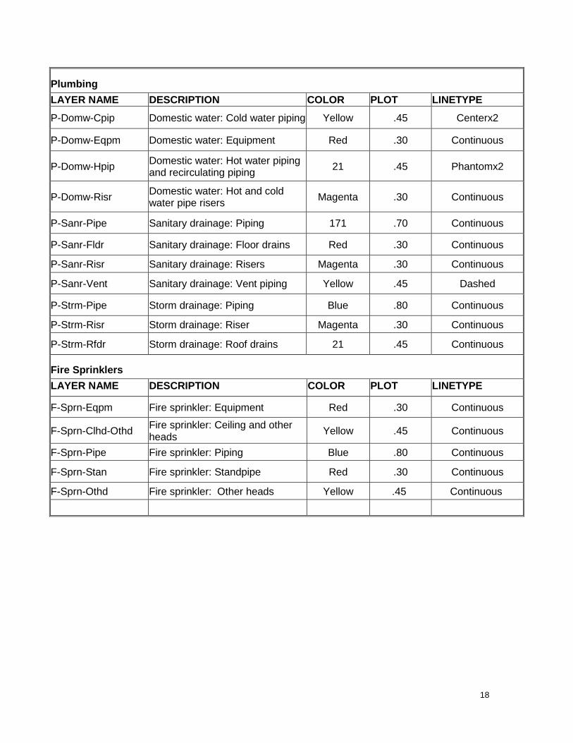
Plumbing LAYER NAME DESCRIPTION COLOR PLOT LINETYPE
P-Domw-Cpip Domestic water: Cold water piping Yellow .45 Centerx2
P-Domw-Eqpm Domestic water: Equipment Red .30 Continuous
P-Domw-Hpip Domestic water: Hot water piping and recirculating piping 21 .45 Phantomx2
P-Domw-Risr Domestic water: Hot and cold water pipe risers Magenta .30 Continuous
P-Sanr-Pipe Sanitary drainage: Piping 171 .70 Continuous
P-Sanr-Fldr Sanitary drainage: Floor drains Red .30 Continuous
P-Sanr-Risr Sanitary drainage: Risers Magenta .30 Continuous
P-Sanr-Vent Sanitary drainage: Vent piping Yellow .45 Dashed
P-Strm-Pipe Storm drainage: Piping Blue .80 Continuous
P-Strm-Risr Storm drainage: Riser Magenta .30 Continuous
P-Strm-Rfdr Storm drainage: Roof drains 21 .45 Continuous
Fire Sprinklers LAYER NAME DESCRIPTION COLOR PLOT LINETYPE
F-Sprn-Eqpm Fire sprinkler: Equipment Red .30 Continuous
F-Sprn-Clhd-Othd Fire sprinkler: Ceiling and other heads Yellow .45 Continuous
F-Sprn-Pipe Fire sprinkler: Piping Blue .80 Continuous
F-Sprn-Stan Fire sprinkler: Standpipe Red .30 Continuous
F-Sprn-Othd Fire sprinkler: Other heads Yellow .45 Continuous
18

Structural LAYER NAME DESCRIPTION COLOR PLOT LINETYPE
FOOTING AND FOUNDATION PLANS S-Ablt Anchor bolts Magenta .30 Continuous
S-Cntr Centerline of footings or anchor bolts 91 .20 Centerline
S-Cols Columns Magenta .30 Continuous
S-Fenc Fence and posts Red .30 Continuous
S-Fndn-Main Main building foundation Yellow .45 Continuous
S-Fndn-Minr Foundation not associated with building 21 .45 Continuous
S-Fndn-Recs Recess in foundation at doors and other openings Red .30 Continuous
S-Foot-Main Main building footings 91 .20 Hidden2
S-Foot-Minr Footing not associated with main building 91 .20 Hidden2
S-Mech-Pads Mechanical pads Red .30 Continuous
S-Slab Slab not associated with building Red .30 Continuous
S-Slab-Opng Opening or recessed areas in slab Red .30 Continuous
Framing Plans
S-Beam Beams (wood, steel and concrete) 14 .53 Continuous
S-Cols Columns Magenta .30 Continuous S-Fram-Blck Blocking 21 .45 Continuous S-Fram-Gird Girders at roof or floor framing 14 .53 Continuous
S-Fram-Jois Roof joists, floor joists or ceiling joists Yellow .45 Continuous
S-Fram-Strt Continuous strut at shear walls Red .30 Hidden2
S-Fram-Trus Trussed rafters or steel trusses Yellow .45 Continuous
S-Obld-Blck Overbuild blocking 21 .45 Continuous S-Obld-Jois Overbuild joists Yellow .45 Continuous
S-Obld-Trus Overbuild trussed rafters Yellow .45 Continuous
S-Plan-Ceil Floor plan background for ceiling framing 140 .13 Continuous
S-Plan-Roof Floor plan background for roof framing 140 .13 Continuous
19

Telecommunications LAYER NAME DESCRIPTION COLOR PLOT LINETYPE T-Comm Communication 150 .30 Continuous
Landscaping LAYER NAME DESCRIPTION COLOR PLOT LINETYPE L-Irrg-Covr Irrigation: Coverage Cyan .18 Dashed L-Irrg-Drip Irrigation: Drip irrigation tubing Magenta .30 Dashed L-Irrg-Eqpm Irrigation: Equipment (pumps,
etc.) Red .30 Continuous
L-Irrg-Ltrl Irrigation: Lateral pipe Green .30 Continuous L-Irrg-Main Irrigation: Mainline Blue .80 Dashed L-Irrg-Slve Irrigation: Pipe sleeve Yellow .45 Short Dash L-Irrg-Spkl Irrigation: Sprinklers (rotors,
heads) Red .30 Continuous
L-Plnt-Beds Landscape: Perennial & annual beds
Cyan .18 Continuous
L-Plnt-Edgr Landscape: Planting bed edger Red .30 Continuous L-Plnt-Evgr Landscape: Evergreen trees
(broadleaf) Green .30 Continuous
L-Plnt-Grnd Landscape: Ground covers Cyan .18 Continuous L-Plnt-Palm Landscape: Palm trees 91 .20 Continuous L-Plnt-Remv Landscape: Materials to be
removed 9 .13 Dashed
L-Plnt-Shad Landscape: Shadow area 8 .18 Dashed L-Plnt-Shrb Landscape: Shrub symbols Green .30 Dashed L-Plnt-Tree Landscape: Trees Green .30 Continuous L-Plnt-Turf Landscape: Lawn areas Green .30 Continuous L-Site Site improvements Magenta .30 Continuous
20

Civil (suggested layer names. Site information is project specific)
LAYER NAME DESCRIPTION COLOR PLOT LINETYPE C-Bldg Buildings & primary structures Yellow .45 Continuous C-Comm Communications Magenta .30 Dashed C-Dfld Drain fields Yellow .45 Dashed C-Eros Erosion & sediment control 9 .13 Dashed C-Esmt Easements Red .30 Dashed C-Fenc Fences 8 .18 Long/short dash C-Fire-Undr Fire sprinkler underground pipe Blue .80 Dashed C-Ngas-Undr Natural gas underground pipe Yellow .45 Dashed C-Prkg Parking lots Magenta .30 Continuous C-Prkg-Conc Parking lots: concrete surface Cyan .18 Continuous C-Prkg-Curb Parking lots: curb Magenta .30 Continuous C-Prkg-Sign Parking lots: signs Yellow .45 Continuous C-Prkg-Strp Parking lots: striping 9 .13 Continuous C-Powr-Undr Power: underground lines Red .30 Dashed C-Prop Property lines Red .30 Long/short dash C-Road Roadways Magenta .30 Continuous C-Road-Cntr Roadway centerline Yellow .45 Centerline C-Rrap Riprap 8 .18 Continuous C-Sswr-Undr Sanitary sewer underground pipe 21 .45 Dashed C-Strm-Undr Storm sewer underground pipe Cyan .18 Dashed C-Swlk Sidewalks Magenta .30 Continuous C-Topo-Depr Topography: Depression contours Yellow .30 Dashed C-Topo-Majr Topography: Major contours 40 .45 Dashed C-Topo-Minr Topography: Minor contours 44 .30 Dashed C-Topo-Spot Topography: Spot elevations Green .30 Continuous C-Wall-Rtwl Walls: Retaining Yellow .45 Continuous C-Watr-Undr Water supply system
Underground pipe Blue .80 Dashed
C-Topo-Exst Topography: Existing contours 246 .30 Dashed
21