architecture database, september 2012
TRANSCRIPT

DataManagement Marta Oliva Solé PID_00184141

CC-BY-NC-ND • PID_00184141 Data Management
The texts and images contained in this publication are subject -except where indicated to the contrary- to an Attribution-NonCommercial-NoDerivs license (BY-NC-ND) v.3.0 Spain by Creative Commons. You may copy, publically distribute andtransfer them as long as the author and source are credited (FUOC. Fundación para la Universitat Oberta de Catalunya (OpenUniversity of Catalonia Foundation)), neither the work itself nor derived works may be used for commercial gain. The full terms ofthe license can be viewed at http://creativecommons.org/licenses/by-nc-nd/3.0/legalcode

CC-BY-NC-ND • PID_00184141 Data Management
Index
Introduction............................................................................................... 5
Objectives..................................................................................................... 6
1. Loss of Data Due to Errors or Failures......................................... 7
2. Data Manager Architecture............................................................ 9
2.1. The Buffer Pool and its Manager ................................................ 9
2.1.1. Buffer Pool Structure ..................................................... 9
2.1.2. Buffer Manager Operations ........................................... 10
2.2. Recovery Manager ....................................................................... 12
2.3. Log ............................................................................................... 12
2.3.1. Log Content ................................................................... 13
2.3.2. Write-Ahead Logging Protocol ...................................... 14
2.3.3. Log Implementation ...................................................... 14
2.3.4. Checkpointing ............................................................... 14
3. Logging Recovery............................................................................... 17
3.1. Logging Recovery Manager Policies ............................................ 17
3.2. Steal/No Force Policy .................................................................. 18
3.3. No Steal/No Force Policy ............................................................ 28
3.4. Steal/Force Policy ........................................................................ 29
3.5. No Steal/Force Policy .................................................................. 30
3.6. Logging Recovery Using the Shadowing Strategy ...................... 30
4. Media Recovery................................................................................... 32
5. Further Aspects in Distributed Databases................................... 34
5.1. Failures in a Distributed System ................................................. 34
5.2. Atomic Commitment Protocols .................................................. 35
5.2.1. Two-Phase Commit Protocol ......................................... 36
5.2.2. Three-Phase Commit Protocol ...................................... 40
5.3. Data Replication .......................................................................... 44
5.4. Media Recovery ........................................................................... 45
Summary...................................................................................................... 46
Self-evaluation............................................................................................ 47
Answer key.................................................................................................. 48

CC-BY-NC-ND • PID_00184141 Data Management
Glossary........................................................................................................ 49
Bibliography............................................................................................... 50

CC-BY-NC-ND • PID_00184141 5 Data Management
Introduction
One of the functions of database management systems (DBMS) is that database
access should be transparent to the user. In this module, we will study the data
manager, which is responsible for physical access to the database.
The purpose of this module is to describe, in the context of a centralized data-
base, the various subcomponents of the data manager and how it works. We
will see how the buffer pool and the buffer manager, together with the recov-
ery manager, work to ensure a consistent database state without the loss of
information. Hence, we will look at logging recovery techniques taking into
account the different policies of the logging recovery manager and we will
deal with media recovery techniques.
Further aspects to consider in the media and logging recovery of distributed
databases are also covered at the end of this module.

CC-BY-NC-ND • PID_00184141 6 Data Management
Objectives
The main objective of this module is to introduce the data management com-
ponent. Specifically:
1. Be aware of why the data stored in a database could be totally or partially
lost.
2. Know which component of the DBMS is responsible for accesses to the
physical database (i.e. non volatile storage) and how it relates to other
components.
3. Understand the behaviour of the data manager and its subcomponents.
4. Be familiar with the log of a DBMS.
5. Learn how the behaviour of the data manager affects recovery mecha-
nisms (logging and media recovery).
6. Distinguish between the different policies of logging recovery manager.
7. Learn to decide which recovery manager policy may be more appropriate
in different circumstances.
8. Understand the reasons why failures occur in distributed databases.
9. Be familiar with the usual atomic commitment protocols in distributed
databases.

CC-BY-NC-ND • PID_00184141 7 Data Management
1. Loss of Data Due to Errors or Failures
During the normal use of a database (DB), a number of situations can occur
that can lead to the loss of stored data. The most common of these are directly
related to the transaction execution process, although others are caused by
system failures or errors in storage devices.
Examples of information loss
The most common type of system failure is when the computer's power supply is shutdown. You will almost certainly have had a power outage while creating a document onmore than one occasion. The first thing we do is to think about the last time that wesaved our work and then estimate how much information we have lost. The same thingapplies when the power goes off while we are performing a transaction to pay moneyinto our bank account. Obviously, the transaction could not be completed and we areleft wondering which balance the bank's database has recorded for our bank account.
Other times, we find, for example, that there is no way to read a document that we hadpreviously saved. In this case, we can say that there is an error in the storage device. Thiscan happen with any storage device on which a database is stored.
We already know what a transaction is and what its properties are. In addi-
tion, read-only transactions are not relevant to the data manager, given that
they do not change the contents of the database. Thus, whenever this module
mentions transactions, it refers to transactions that have made at least one
change in the database (in short, read-write transactions). In this section, we
will see how the atomicity and the durability properties require a series of ac-
tions to be carried out in certain circumstances in order to make sure that the
database contains accurate information:
1) Since a transaction must be atomic, all of the changes it contains must
remain in the database as a unit in case the transaction commits. On the other
hand, whenever a transaction cannot be completed, regardless of the reason
(e.g. because it was voluntarily aborted, the system crashed, etc.), it will be
necessary to undo all changes.
2) The durability property requires all changes made by committed transac-
tion to be permanent. Given that, for the sake of efficiency, a buffer pool is
always used and each change made in the buffer pool does not have to be re-
flected immediately on the storage devices, we must be sure that any changes
made by committed transactions are also made permanent. This is why, in cer-
tain circumstances, it is necessary to redo changes that were only recorded in
the buffer pool and lost for various reasons (the system crashed, for example).
Undo and redo techniques are referred to as logging�recovery�techniques.
When errors occur in the storage devices, we need to use media� recovery
techniques to solve them. Thus, logging recovery techniques are used to solve
problems arising from errors in software, while media recovery techniques
ACID properties oftransactions
The ACID properties of trans-actions are:• Atomicity• Consistency• Isolation• Durability

CC-BY-NC-ND • PID_00184141 8 Data Management
are used to deal with problems caused by hardware failures. To describe both
logging and media recovery techniques, we will use the general term recovery
techniques.
The data�manager, available in all DBMS, must deal with any read and/
or write operations made to the DB. It is also responsible for executing
the actions ensuring that the DB information is correct (logging and
media recoveries) in the simplest, quickest and most automated way
possible, avoiding human intervention when possible.
To allow the data manager to correctly and automatically perform the actions
to ensure that the database is correct, redundant data must be stored. The
elements allowing us to store information in such a way that the database
can be recovered are, firstly, the log and backups, and, secondly, an identical
copy or mirror of the DB so that, when it is not possible to access the original
copy, we can work on the mirror copy.

CC-BY-NC-ND • PID_00184141 9 Data Management
2. Data Manager Architecture
We have already seen a functional architecture that also includes an architec-
ture for the data manager. We can see that the data manager has three rele-
vant subcomponents: the buffer pool, the buffer manager and the recovery
manager. There is an additional essential component for the operation of the
data manager: the log. In the following subsections, we will look in detail at
these subcomponents to determine what they are and how they work.
2.1. The Buffer Pool and its Manager
The data manager uses a buffer pool because, as you know, it helps speed up
the process, thereby improving efficiency. Typically, the operating system is
responsible for reading and writing to the buffer pool. Given its importance
in the efficiency of recovery techniques, the DBMS and, more specifically, the
data manager is responsible for its handling through the buffer manager.
2.1.1. Buffer Pool Structure
The buffer pool used by the data manager is designed to ensure recovery.
Hence, the smallest unit of information that we can store in it is a disk page of
the database. Given that a set of buffer slots is available to us, we can maintain
a collection of disk pages in the buffer pool.
Figure 1
To determine which disk pages are in the buffer, we have a directory. Figure
1 shows how each directory entry contains the address of the disk page and a
pointer to the position of the buffer slot at which the disk page is stored. In
addition, linked to each buffer slot, we will have:

CC-BY-NC-ND • PID_00184141 10 Data Management
a) A bit used to indicate whether the contents of the buffer slot have changed.
This is referred to as a dirty�bit. If there is no change, the bit will remain at 0,
while we will switch it to 1 if changes have been made.
b) Another bit that allows us to keep the page in the buffer slot as though we
were pinning it down in order to keep it there without flushing until we wish
to do so. This bit is called pin/unpin bit. We will switch this bit to 1 whenever
we want to pin the page to the buffer slot and set it to 0 when we want to
unpin it. By being able to pin and unpin a page in the buffer slot, we ensure
that the read/write operations are atomic since we avoid the flushing of the
buffer slot contents while the operations are being executed.
2.1.2. Buffer Manager Operations
The buffer manager provides the fetch and flush operations. The fetch
operation reads a page of the DB and loads it in the buffer pool. On the
other hand, the flush operation stores the content of a page, located in
the buffer pool, in the DB.
In the procedure for the flush operation, shown below, we must indicate the ID
of the page to remove from the buffer pool, considering that the page cannot
be pinned, i.e. the pin/unpin bit must be 0 in order that the procedure can
be performed.
procedure flush(p: page_id)var w: page_value;
if dirty(p) = 1 then w := content(p); write_page (p, w); dirty(p) := 0; endIf update_directory(p, 0);endProcedure
The first thing it does is to ensure that the page is stored correctly on the
device where the DB is stored. So, if the dirty bit indicates that the page has
been modified (the dirty bit is equal to 1), a write_page operation is performed,
indicating that, from that point, the page is no longer changed (the copy in the
buffer slot and the copy on the storage device are the same). To complete the
procedure, the directory entry corresponding to the buffer slot that contained
the flushed page is updated to show that there is no DB page in that buffer
slot (the page ID is set to 0), as well as the dirty and the pin/unpin bits. From
this point, the buffer slot is available to fetch another page.
The fetch operation works as follows:
Dirty bit
This bit is called a dirty bit be-cause it is considered that thephysical page is dirty (invalid)and needs to be changed be-cause a modification has beenmade.

CC-BY-NC-ND • PID_00184141 11 Data Management
procedure fetch(p: page_id)var w: page_value; b: page_id; if search(0) = 0 then <choose a buffer slot b according to LRU or FIFO>; flush(b); endIf read_page (p, w); update_directory (0, p); content(p) := w;endProcedure
Firstly, a free buffer slot must be found, bearing in mind that free buffer slots
have 0 as their page ID. If there is none available, a buffer slot that can be
flushed (using the LRU or FIFO technique) is chosen among the buffer slots
that do not contain pinned pages. Once a free buffer slot is available, the page
with the given page ID is physically read. The directory entry corresponding
to a free buffer slot is then updated to indicate the ID of the page that was just
read and, finally, the page contents are stored in the buffer slot.
Note that whenever a page is fetched, the DB has to be read; however, when a
page is flushed, it is not always necessary to write the DB. The writing is only
performed in the DB if the page has been changed in the buffer pool.
It is important to note that a page can be flushed using two different strategies,
depending on the data manager. Some data managers maintain more than
one version of each page on the storage device, while others only keep one. If
the data manager has a single version of each page in the storage device, each
update will overwrite the page, which is stored in the same location of the
original storage device. Thus, the information it contained before the change
was made is lost. This method is called in-place�updating. If the data manager
maintains different versions of a page in the storage device, it will not be
necessary to overwrite the old version of the page with each update; instead,
a new position can be found on the storage device. This technique is referred
to as the shadowing�technique because each old version of a page is called
a shadow.
The LRU and FIFOtechniques
The LRU acronym stands forLeast Recently Used.The FIFO acronym stands forFirst In, First Out.

CC-BY-NC-ND • PID_00184141 12 Data Management
Figure 2
The shadowing strategy requires a directory with as many positions as pages
the DB has. Each directory entry contains the page ID and its physical location
on the storage device. Each of these directories is used to define a state of the
DB. As shown in Figure 2, several of these directories are generally maintained,
so different DB states are available. We will see how this strategy can facilitate
the tasks of the recovery manager.
2.2. Recovery Manager
The recovery manager is the main subcomponent of the data manager
of any DBMS. It includes both the logging and media recovery man-
agers. The logging manager is responsible for logging recovery tech-
niques, while the media manager deals with media recovery techniques.
Given the importance of these two managers, we will devote section 3 of this
module to the logging recovery manager and section 4 to the media recovery
manager.
2.3. Log
The log is a component that is essential to the data manager operation, pro-
vided that the data manager uses the in-place updating strategy to flush pages.
The log is used for the storage of information about performed changes
so that the recovery manager can restore a consistent state of the DB.
Note
The log can also be called jour-nal.

CC-BY-NC-ND • PID_00184141 13 Data Management
2.3.1. Log Content
Conceptually, a log is a representation of the history of executed trans-
actions and the changes they have made in the DB. Entries are recorded
in the log whenever these transactions commit, abort or update data.
Each entry, regardless of the type of operation to which it corresponds, must
contain the following information: the ID of the transaction to which the
operation relates, the type of operation and a pointer to the entry, saved pre-
viously in the log, corresponding to the prior operation in this transaction.
Additional information must also be saved for the updating operation, as we
shall see below.
By checking the log, we should be able to determine the last committed value
of data. There are two ways of storing this information in the log:
1) Indicating the written value for each entry corresponding to an update
operation; this gives us a physical�log.
2) Instead of storing the value, we save the description of the high-level oper-
ations performed on the data; hence we have a logical�log.
The logical log requires less entries to record changes, which improves the
performance of the recovery manager. By contrast, recovery from a logical log
is usually more complex. Therefore, and since it is more common for managers
to use physical logs, from now we will only discuss physical logs.
All physical logs must have the necessary information to undo the changes
made by transactions that have not committed. This information (named be-
fore�image) corresponds to the value of the data before it was modified by
the transaction.
The physical log must also contain the information needed to redo the
changes of committed transactions that were not stored in the DB. In this
case, the information (known as after�image) corresponds to the value of the
updated data.
Thus, besides the information shared with the other entries stored in the log,
any entry corresponding to an update operation also includes the ID of the
page that has been changed, as well as its before and after images.
Example of an entry in alogical log
Entries in a logical log can be:"insertion of the record R in fileF and updating the index of Fto reflect the insertion."

CC-BY-NC-ND • PID_00184141 14 Data Management
2.3.2. Write-Ahead Logging Protocol
To ensure correct log entries, the recovery manager follows the write-ahead
logging protocol (WAL).
The write-ahead�logging�protocol ensures that the before image of a
page is recorded in the log before the page is overwritten in the DB with
the after image value of the page.
In a similar way, this protocol does not allow the commit operation of a trans-
action to be completed until the log contains the entries for all of the opera-
tions performed by the transaction.
2.3.3. Log Implementation
Physically, a log is an auxiliary file in which information about all
changes made by the transactions over the DB is recorded.
Given the importance of maintaining the order in which the changes have
been made, sequential files are the best storage option. The sequential file that
implements the log has a seemingly unlimited capacity. However, given that
no storage device has an unlimited capacity, the file has assigned a limited
capacity and a link from the bottom of the file to the top is added allowing us
to continue adding entries from the begining of the file once its end is reached.
In addition, to guarantee availability of the log (any file can contain errors),
two copies are usually stored and regular backups are made.
2.3.4. Checkpointing
Given that log entries are being written continuously and the sequential file
that maintains the log is regularly overwritten, we should think about the
following:
a) If entries are overwritten when the capacity allocated for the file that im-
plements the log has been exceeded, what happens with the lost information?
b) If the log entries are stored from the start of the operation of the DB, if it is
necessary to restore a correct (or consistent) state of the DB, how much work
will the data manager have to do and how long will this take?
The problems posed in these questions can be solved with the inclusion in
the log of checkpointing entries.

CC-BY-NC-ND • PID_00184141 15 Data Management
Checkpointing is a method that forces the physical storage of a con-
sistent state of the DB and simultaneously allows that some (and some-
times even all) of the log entries made prior to the checkpointing could
be ignored in case of failures.
Checkpointing is automatic and regular. A specific frequency can be set (for
example every fifteen minutes). There are different types of checkpointing,
being the most common ones transaction-consistent and action-consistent.
When a transaction-consistent checkpointing is applied, the following steps
are performed:
1) The execution of transactions is temporary suspended. This means that no
new transactions can be executed, although active transactions are allowed
to be completed.
2) Flushing of all changed buffer slots is forced (these buffer slots have their
dirty bit set to 1 in the directory) to the external device where the database
is stored.
3) A checkpointing entry is written in the log to record that a consistent state
has been saved in the DB.
4) The execution of new transactions is resumed.
With this checkpointing method, the DB contains the last committed values
of the transactions that were being executed during checkpointing. Hence,
the method is also known as commit�consistent�checkpointing. Note also
that all log entries made before the checkpointing can be ignored in the event
of software failure (i.e. logging recovery).
In some systems, especially those overloaded, waiting for transactions comple-
tion has the disadvantage of requiring too long a waiting time (during which
the system is inoperative), from the point where the execution of new trans-
actions is no longer accepted to when it is resumed. Hence, instead of trans-
action consistent checkpointing, some systems use action-consistent�check-
pointing.
Action-consistent checkpointing requires executing the same set of steps as for
transaction-consistent checkpointing. However, rather than waiting for all ac-
tive transactions to finish their execution in order to store a consistent state of
the DB, only the actions of the active transactions at the start of checkpoint-
ing are allowed to finish their execution. This new procedure is also known
as buffer�pool�consistent�checkpointing.
Action
Remember that the term ac-tion is used to refer to an el-ementary operation on thedatabase that can be found ina transaction.

CC-BY-NC-ND • PID_00184141 16 Data Management
Note that action-consistent checkpointing allows the flushing of buffer slots
modified by transactions that have not yet committed. In this case, we cannot
disregard the information stored in the log prior to checkpointing entry and,
in certain situations, we will need to use the entries prior to a checkpointing
entry to undo all of the changes made by transactions that have aborted rather
than committed.
The checkpointing entry stored in the log for action-consistent checkpointing
includes additionally a list of all transactions that were active when the check-
pointing was performed. This information helps to determine which entries
before the checkpointing entry are relevant.
In the following sections of this module, we will learn how the logging and
media recovery managers use the log to recover the database when necessary.

CC-BY-NC-ND • PID_00184141 17 Data Management
3. Logging Recovery
The logging�recovery�manager, which is part of the recovery manager,
is responsible for receiving and executing operations sent by the con-
currency manager. Each operation is executed in such a way that allows
logging recovery techniques to be used when necessary.
Specifically, the operations offered by the logging recovery manager to the
concurrency manager are: read, write, commit and abort. There is also a restart
operation, which runs automatically whenever the system is restarted (after
a crash, for example).
The logging recovery manager executes each operation atomically. It uses the
buffer pool, through the buffer manager, to improve the efficiency of both
reading and writing operations, although not all logging recovery managers
use the buffer pool in the same way.
3.1. Logging Recovery Manager Policies
Sending operations to thedata manager
The concurrency managersends the operations to the da-ta manager in such a way thatguarantees the seriability oftransactions executed concur-rently.
Depending on how the buffer slots are assigned to transactions, and depend-
ing on when the stored pages are flushed from the buffer slots to the storage
device where the DB is saved, we can distinguish between different logging
recovery manager policies:
1) If the logging recovery manager shares the buffer pool among all active
transactions, such that each buffer slot is assigned to any transaction when
needed, the logging recovery manager will need to work in steal policy. This
policy is so called because any transaction allows any of the buffer slots that
were assigned to it to be taken when another transaction needs them, even
when the transaction is still active. Thus, in this policy, pages are never pinned
in the buffer pool (i.e. the pin/unpin bit will always be set at 0).
2) The logging recovery manager can also maintain (pin) all the pages that a
particular transaction requires during its execution in the buffer pool. In this
case, the logging recovery manager runs in no�steal policy, since no other
transaction can take the buffer slots occupied by another active transaction.
3) If the logging recovery manager forces flushing all buffer slots assigned to
a particular transaction at the moment that it is committed, then the logging
recovery manager will run in force policy.
Allocation of buffer slotsto transactions
We can find out which bufferslots were assigned to atransaction if we scroll backthrough the log. Another op-tion is to have the logging re-covery manager buffer main-tains a list of assigned bufferslots for each transaction.

CC-BY-NC-ND • PID_00184141 18 Data Management
4) When the logging recovery manager does not force flushing of the buffer
slots assigned to a committed transaction, the logging recovery manager poli-
cy is no�force. In this policy, each buffer slot is flushed only when it is required
in order to fetch a new page.
We must take into account the following considerations:
a) In no steal policy, it is impossible to flush a buffer slot that has been modi-
fied by a non committed transaction, except for buffer slot flushings triggered
by the addition of an action-consistent checkpointing entry. This ensures that
it will not be necessary to undo changes prior to the last checkpointing entry.
b) With the sharing of buffer slots among different transactions, as occurs in
the steal policy, before a new page can be fetched on a buffer slot, perhaps the
content of the chosen buffer slot must be flushed. Whenever a logging recov-
ery manager uses the steal policy, we must be aware that it may be necessary
at some point to undo the changes made by transactions that did not commit
and which have been physically stored in the database.
c) By forcing the flushing of buffer slots, we ensure that the changes made by
committed transactions are reflected physically in the database at the point
of their commit. This ensures that it will never be necessary to redo changes
made by committed transactions when the logging recovery manager uses the
force policy.
d) If the logging recovery manager does not force flushing the buffer slots
changed by a committed transaction, changes may be lost if, for example, the
system crashes. In the no force policy, we must anticipate the need to redo
changes performed by committed transactions that have been lost.
e) In the no steal policy, a higher number of buffer slots is required than in
the steal policy. Note that with the no steal policy, the buffer pool must, at
the very least, have as many buffer slots as different pages could be modified
by a transaction.
f) The no force policy allows buffer slots to be flushed according to the need
to fetch new pages. Therefore, unnecessary flushings that could have been
caused by the force policy are avoided, given that the number of input/out-
put operations is also minimised. It may occur that, when the execution of
a transaction begins, it requires the pages modified by a transaction that has
just previously committed.
3.2. Steal/No Force Policy
Logging recovery managers that run in a steal/no force policy, despite requir-
ing both undo and redo mechanisms, are the most common type in DBMSs.
Despite the complexity, this policy is the one that uses the resources most

CC-BY-NC-ND • PID_00184141 19 Data Management
efficiently, both in terms of the amount of memory allocated in the buffer
pool and the number of input/output operations generated in fetching and
flushing the physical pages.
As it has been mentioned throughout this module, we assume that the buffer
manager flushes the pages using the in-place updating strategy. Note also that
a physical log is used. Similarly, we will consider that checkpointing entries
are action-consistent.
We will now see how the operations offered by the logging recovery manager
to the concurrency manager have to be implemented. This implementation
must be consistent with the chosen policy (steal/no force). Specifically, we will
look at the following operations: read, write, commit, abort and restart.
As shown below in the procedure for the read operation, we simply need to
obtain the contents of the page after ensuring that the page is not currently
available in the buffer slots.
procedure read(t: transaction_id, p: page_id, v: page_value) if search(p) = 0 then fetch(p); endIf v := content(p);endProcedure
The procedure for the write operation shows that, after ensuring that the page
is fetched in the buffer pool and before the chosen buffer slot for this page
is modified, the entry corresponding to the desired modification is written in
the log according to the write-ahead logging protocol. Note that the log entry
includes the type of action ('u'), the ID of the transaction that submits the
operation (t), the ID of the page being changed (p), the before image (w) and,
lastly, the after image (v). Note that the logging recovery manager also adds
the pointer to the previous log entry of the same transaction.
procedure write(t: transaction_id, p: page_id, v: page_value) var w: page_value; if search(p) = 0 then fetch(p); endIf w := content(p); write_log('u', t, p, w, v); content(p) := v; dirty(p) := 1;endProcedure
After the content of a buffer slot is changed, its corresponding dirty bit in
the directory is always updated so that the page is physically stored when the
buffer slot is flushed.

CC-BY-NC-ND • PID_00184141 20 Data Management
In the no force policy, the pages modified by a committed transaction do not
have to be flushed, so the commit operation simply needs to write in the log
that the transaction (t) is committed ('c').
procedure commit(t: transaction_id) write_log('c', t);endProcedure
When a transaction needs to be aborted because the logging recovery manager
receives the abort operation from the concurrency manager, all changes made
by the transaction must be undone because, in the steal policy, some of these
changes may be physically recorded in the DB.
Thus, the abort procedure must read the log backward, from the last entry of
the transaction, to the first one, in order to recover all before images of the
pages updated by the aborted transaction. For each updating entry ('u'), we
must ensure that the page (p) is fetched to the buffer pool and we must then
modify the contents of the buffer slot containing the page (p) with the before
image ('w') read from the log. It is essential to set the dirty bit for the buffer
slot containing the page (p) to 1 so that the value is physically stored when
the page will be flushed. Finally, the procedure will write in the log that the
transaction (t) aborted ('a').
procedure abort(t: transaction_id)var p: page_id; w: page_value; read_log_backwards('u', t, p, w); while records_remain_in_log ('u', t) do if search(p) = 0 then fetch(p) endIf content(p) := w; dirty(p) := 1; read_log_backwards('u', t, p, w); endWhile write_log('a', t);endProcedure
Using an example, we will illustrate the execution of each of the operations
that the logging recovery manager offers to the concurrency manager in the
steal/no force policy. Figure 3 shows the DB state, the buffer pool stucture and
the log. Given that we are starting from an initial state, we can assume that
the buffer pool structure and the log are empty.

CC-BY-NC-ND • PID_00184141 21 Data Management
Figure 3
The logging recovery manager receives the following sequence of operations:
a) read(T1,P1,v1)
b) write(T1,P1,8)
c) read(T3,P5,v3)
d) write(T3,P5,1)
e) read(T1,P2,v1)
f) read(T2,P3,v2)
g) write(T2,P3,29)
h) abort(T1)
i) read(T3,P8,v3)
j) write(T3,P8,17)
k) read(T2,P2,v2)
l) write(T2,P2,6)
m) read(T4,P20,v4)
n) write(T4,P20,50)
o) commit(T2)
p) auto_checkpointing
q) read(T5,P14,v5)
r) write(T5,P14,7)
s) read(T3,P3,v3)
t) write(T3,P3,18)
u) read(T4,P1,v4)
v) read(T6,P2,v6)
w) write(T6,P2,32)
x) commit(T6)
Figure 4 shows how the different buffer slots have been filled, with directory
updating, and the entries added to the log, taking into account that the log-
ging recovery manager has executed from operation a) to operation e).

CC-BY-NC-ND • PID_00184141 22 Data Management
Figure 4
At this point, in order to execute the operation f), which requires fetching
page P3, we must flush one of the buffer slots. Assuming that the policy is steal
(hence, there are no pinned pages) and that we will use the FIFO technique,
the buffer slot we must flush is the one that contains page P1. Since this page
has been changed, it will be physically stored in the database. We can see the
overall result after executing operation f) in Figure 5.
Figure 5
Activity
Simulate the execution of the other operations, from operation g) to operation x), takinginto account that in operation p), as indicated, an action-consistent checkpoint is auto-matically perfomed. Note that when a transaction is committed, the buffer slots assignedto it do not have to be flushed (no force policy).
In Figure 6, we can see the final state after applying all the operations. All of
the entries that must be contained in the log are also listed.

CC-BY-NC-ND • PID_00184141 23 Data Management
Figure 6
Log entries
The execution of all the operations, from a) to x), will generate the following log entries:
1. 'u', T1, P1, 4, 8, nil
2. 'u', T3, P5, 2, 1, nil
3. 'u', T2, P3, 6, 29, nil
4. 'a', T1, 1
5. 'u', T3, P8, 3, 17, 2
6. 'u', T2, P2, 11, 6, 3
7. 'u', T4, P20, 1, 50, nil
8. 'c', T2, 6
9. 'cp', {T3, T4}
10. 'u', T5, P14, 29, 7, nil
11. 'u', T3, P3, 29, 18, 5
12. 'u', T6, P2, 6, 32, nil
13. 'c', T6, 12
The restart operation is responsible for restoring a consistent (i.e. correct) state
of the DB after a system failure. Any changes made by transactions that did
not commit and were stored in the database must be undone and the changes
made by committed transactions that were lost must be performed again.
Given its complexity, we will deal with the restart procedure at two levels: In
the first one, we will describe the main actions to be undertaken, while in the
second, we will discuss each action in detail.

CC-BY-NC-ND • PID_00184141 24 Data Management
procedure restart()var CL: commit_trans_list; AL: abort_trans_list; p: page_id; w: before_image_page; v: after_image_page; t: transaction_id; r: entry_type; d: log_position; buffer_and_transaction_lists_reset (); undo_to_last_CP_phase (); undo_complementary_phase (); redo_phase (); enter_CP ();endProcedure
At the first level, we can see that the restart procedure consists of five actions:
1) The buffer_and_transaction_lists_reset action resets the buffer pool so that
there is no information previous to the crash in any buffer slot. The commit
and abort transaction lists are also set to empty.
2) The undo_to_last_CP_phase action undoes all changes made by transactions
that were active when the crash occurred, or the changes performed by trans-
actions that were intentionally aborted. This action only deals with log entries
from the end of the log up to the last checkpointing. During this phase, by
examining the log, both the lists of committed and uncommitted transactions
are deduced.
3) The undo_complementary_phase complements the undo phase performed in
the previous action. When the last checkpointing entry is read from the log,
the list of transactions that were active when the checkpointing log entry was
performed is obtained. The final set of transactions to be undone is deduced
from this list and the committed and aborted lists created during the previous
undo phase. Note that this action is not necessary if transaction-consistent
checkpointing is used.
4) The redo_phase action corresponds to the redo phase. During this phase,
starting from the last checkpointing log entry, all the changes perfomed by
committed transaction are redone.
5) The enter_CP action is the last task in the restart procedure and consists
of making a checkpointing entry in the log to indicate that the database is
consistent from that point on. The list of active transactions is empty.
We will now turn to look at the second level:
1) The reset_buffer_and_transaction_lists action updates each buffer slot to en-
sure that the buffer pool is empty. It also resets to empty the committed trans-
action list (CL) and the aborted transaction list (AL).

CC-BY-NC-ND • PID_00184141 25 Data Management
procedure buffer_and_transaction_lists_reset() for each buffer_slot(p) do dirty(p) := 0; pin(p) := 0; update_directory(p, 0); endFor CL := Ø; AL := Ø;endProcedure
2) The undo_to_last_CP_phase action reads the log backwards until it reaches
the last checkpointing entry. It analyses whether each read log entry corre-
sponds to a commit or abort log entry, and builds the CL and AL lists. If the
log entry corresponds to an update operation, it then undoes the change if it
belongs to a non-committed transaction.
At the end of the undo_to_last_CP_phase action, in a variable (d), the position
of the last checkpointing entry of the log is recorded. This information is to
be used in the redo phase.
3) In the undo_complementary_phase action, firstly, the aborted transaction list
(AL) is completed with the ID of the transactions that were active when the
checkpointing log entry was performed that do not appear in CL or AL. At
this point, the log is read backwards and, if the update log entry that is read
matches any of the remaining transactions in AL, the change indicated in the
read log entry is undone.

CC-BY-NC-ND • PID_00184141 26 Data Management
Keep in mind that if the checkpointing log entry were transaction-consistent,
as opposed to action-consistent, the undo_complementary_phase action would
be unnecessary.
4) The redo_phase action, begining from the last checkpointing log entry, reads
the log forwards and redoes all changes recorded in the update log entries for
the transactions included in CL.
5) The write_db action is used in the other actions of the restart procedure. It
is responsible for physically storing a given page in the DB.
procedure write_db(p: page_id, w: page_value) if search(p) = 0 then fetch(p) endIf content(p) := w; dirty(p) := 1; flush(p);endProcedure
6) The enter_CP action only records a checkpointing entry in the log. The ac-
tive transaction list is empty, since there is no active transaction in the system.
procedure enter_CP()var ATL: active_transaction_list; ATL := Ø write_log('cp', ATL);endProcedure

CC-BY-NC-ND • PID_00184141 27 Data Management
Activity
Let us suppose that after operation x) in the previous example, the system crashed. Sim-ulate the execution of the restart procedure that the logging recovery manager must per-form in order to restore the system and ensure a consistent DB.
Figures 7, 8 and 9 show the result after execution of the undo_to_last_CP_phase,
undo_complementary_phase and redo_phase actions, respectively.
a) Execution of the undo_to_last_CP_phase action:
Figure 7
b) Execution of the undo_complementary_phase action:
Figure 8
c) Execution of the redo_phase action:
Note
Given that the contents of thebuffer slots are unknown aftera failure, these are initialised.Nonetheless, figures 7, 8 and9 consider that each buffer slothas retained the content avail-able before the failure.

CC-BY-NC-ND • PID_00184141 28 Data Management
Figure 9
3.3. No Steal/No Force Policy
Logging recovery managers that run in no steal/no force need only anticipate
the need to redo the lost changes that correspond to committed transactions.
Given that the no steal policy is used, there will be no need to undo any
changes with the exception of those saved following action-consistent check-
pointing.
The code associated to the operations offered by the logging recovery manager
to the concurrency manager differs from the ones we looked at the steal/no
force policy in the following ways:
1) The read operation: the main part is the same as for the procedure in the
steal/no force policy, but after fetching the page, it must be pinned (the pin/
unpin bit is set to 1) because it works with the no steal policy.
2) The write operation: if the page has to be fetched, it must also be pinned as
in the read operation. The other difference is that it will not be necessary to
record the before image of the updated page in the log entry because it will
not be necessary to undo changes, unless the action-consistent checkpointing
is used.
3) The commit operation: it is not necessary to flush the buffer slots but they
must be unpinned (the pin/unpin bit for all buffer slots assigned to the com-
mitted transaction must be set to 0). As in the previous policy, the entry must
be recorded in the log.
4) The abort operation: in the no steal policy, it is not possible to physically
record any uncommitted change, so initially nothing needs to be undone.
Note that if action-consistent checkpointing is used, on aborting, it will be
necessary to undo the changes made by the aborted transaction, in order to

CC-BY-NC-ND • PID_00184141 29 Data Management
prevent changes being saved as a consequence of a checkpointing. We must
also unpin the buffer slots assigned to the aborted transaction and make the
corresponding entry in the log.
5) The restart operation: as we have seen, in this policy, we only need to redo
the changes made by committed transaction. Thus, for the five actions that we
learned for the steal/no force policy, the buffer_and_transaction_lists_reset ac-
tion will be the same, for the undo_to_last_CP_phase action, the log will simply
be read backwards until the last checkpoiting in order to identify the trans-
actions that had committed before the crash. The undo_complementary_phase
action will only be necessary if the action-consistent checkpointing is used,
and the other two actions will be identical.
3.4. Steal/Force Policy
Logging recovery managers that run in steal/force policy only have to undo
the changes performed by transactions that have not committed but which
may have been physically recorded.
The code associated to the operations offered by the logging recovery manager
to the concurrency manager differs from those that we have studied in the
following ways:
1) The read operation is the same as for the procedure in the steal/no force
policy.
2) The write operation is the same as for the procedure in the steal/no force pol-
icy except that it will not be necessary to save the after image of the changed
page in the log, since it will not need to be redone at any time.
3) For the commit operation, it is necessary to flush the changed buffer slots
assigned to the committed transaction and then record the corresponding log
entry. Due to the steal policy, it is possible that only a small number of buffer
slots assigned to the transaction must be flushed.
4) The abort operation is the same as for the procedure in the steal/no force
policy.
5) The restart operation: as we saw at the beginning of this subsection, we
only have to undo uncommitted changes. Thus, the five actions that we have
learned for the steal/no force policy, everything will be identical except for
the redo_phase action, which is not necessary.
Recording of after image
Although the after image isnot needed for logging recov-ery, it is usually recorded be-cause of its importance for me-dia recovery.

CC-BY-NC-ND • PID_00184141 30 Data Management
3.5. No Steal/Force Policy
Logging recovery managers that run in no steal/force are not required to undo
or redo changes under any circumstances.
The code associated to the operations will differ from the ones that we have
already seen in the following ways:
1) The read operation is the same as for the procedure in the no steal/no force
policy; thus, after fetching the page, the assigned buffer slot must be pinned
(the pin/unpin bit is reset to 1).
2) The write operation: if it is necessary to fetch the page, it must be pinned
in the same way as for the read operation. It will be necessary to proceed as in
the steal/no force policy, taking into account the fact that it is not necessary
to save the after image of the changed page, since at no time will be necessary
to redo it.
3) For the commit operation, it is necessary to flush the buffer slots assigned
to the committed transaction and then record the corresponding log entry, as
with the steal/force policy. Note that the buffer slots must be unpinned before
they can be flushed.
Recording of the afterimage
Again, although the after im-age is unnecessary for loggingrecovery, it is usually recordedbecause of its importance formedia recovery.
Since we must guarantee that flushing will be atomic, the shadowing tech-
nique must be used; hence, this policy is not feasible if the buffer slots are
flushed using the in-place updating technique.
4) The abort operation uses the same abort procedure proposed in the no steal/
no force policy.
5) For the restart operation, the undo and redo phases are innecessary. The
complementary_undo_phase will be executed if action-consistent checkpointing
is applied. The initialisation of the buffer pool structure and the addition of a
checkpointing entry in the log will be required as in the other policies.
3.6. Logging Recovery Using the Shadowing Strategy
The logging recovery mechanisms for the restart procedure that we looked at
in the previous subsections used the log. This structure is essential in systems
based on the in-place updating technique.
See also
For logging recovery using theshadowing technique, see sub-section 3.6 of this module.
We have seen that the other page flushing strategy that can be used by the
logging recovery manager is shadowing, and we have also seen that this strat-
egy facilitates the tasks of the logging recovery manager.
See also
Read back over subsection2.1.2 of this module to remindthe shadowing strategy.

CC-BY-NC-ND • PID_00184141 31 Data Management
With the shadowing strategy, a different physical space is always used to store
the page after it has been modified (i.e. the page is not overwritten) and the
old value of the changed page is maintained. Hence, different directories can
be used to determine the different states of the DB.
If we assume that changes are always physically stored, there is no need to
redo any lost changes as a result of a crash. Moreover, rejecting the changes
made by a transaction that was unable to commit is as easy as rejecting the
new directory and new pages generated as a result of the execution of the
transaction and considering the shadow directory and pages as valid instead.
In this case, then, we can guarantee that the logging recovery mechanism
does not need to undo or redo. The only complication with this technique is
locating enough free space for the storage of new pages and the new directory
when necessary, and freeing up the space that they occupy when they need
to be rejected. Whenever a transaction commits, the old pages addressed by
the shadow directory can be rejected.
Usefulness of directories
With directories, we can findout the state of the databasebefore the execution of atransaction began; moreover,with another directory, we canindicate the new state of thedatabase after the execution ofthe transaction.

CC-BY-NC-ND • PID_00184141 32 Data Management
4. Media Recovery
The media�recovery�manager, which forms part of the recovery man-
ager, uses media recovery techniques whenever there is a partial or total
loss of the DB due to errors in hardware components.
Both the log and backups are essential for media recovery.
When a total or partial loss of the DB is detected due to the failure of a hard-
ware component, we must follow the steps below to recover the lost data:
1) Replace or repair the hardware component causing the problem.
2) Locate the backup made immediately before to the date on which the error
occurred, given that this is the copy that contains the most accurate informa-
tion about the database state at the time of the loss.
3) Copy the contents of the backup in order to recover the database.
4) In order to complete the media recovery, use the log to redo all the com-
mitted changes performed between the date when the backup was made and
the current date.
This procedure can also be used to correct changes made to the DB that were
later found to be incorrect.
Moreover, entries made prior to a checkpointing that were rejected are not
lost, as they are always kept on log backups to guarantee the availability of all
log entries required for media recovery.
Likewise, in order to guarantee the availability of the data required for media
recovery, if the DBMS does not have a log because it uses the shadowing tech-
nique to flush buffer slots, backups of the shadow pages and directories are
made.
Nonetheless, there is another way to overcome the problem of total or partial
DB loss, which is to have a copy of the database.
Types of backup
There are different types ofbackup:• Static• Dynamic• Full• Incremental

CC-BY-NC-ND • PID_00184141 33 Data Management
When a DB system has a mirror or secondary copy besides the primary copy of
the database, in the event of an error in the storage device of the primary copy,
we can immediately use the mirror copy without this change affecting users.
We can reconstruct the lost part of the primary copy from the secondary copy.
Although backups may seem unnecessary if we have a mirror, they are often
made in case there are also problems with the secondary copy.
To ensure that the mirror does not have the same problem as the primary
copy, they must be stored on a different device. For each database copy, a log
is also stored on different devices.
During normal database operation, all readings are made to the primary copy.
When a write is recorded, both copies need to be updated to make them iden-
tical. So as not to reduce the response time of the DB, instead of updating
the two copies at the same time, the primary copy is updated first, followed
by the mirror update. Thus, having a mirror increases read capacity but not
write capacity.

CC-BY-NC-ND • PID_00184141 34 Data Management
5. Further Aspects in Distributed Databases
Information is not always stored in a centralised database; sometimes we need
to share the information among several sites of a distributed system. It is there-
fore essential to consider other aspects in addition to those covered in previ-
ous sections, relevant only to distributed databases.
5.1. Failures in a Distributed System
With distributed databases (DDBs), we must guarantee the property of atom-
icity and the property of durability of transactions, just as we did with cen-
tralised databases. The difference this time is that a DDB transaction, called a
global�transaction, is divided into subtransactions that must be executed in
the various sites (or nodes) that comprise the distributed system.
Given that each site has its own data manager, we can consider that the re-
covery in each local database will be guaranteed by the site itself. However,
this is not enough to ensure the correct execution of a global transaction. To
guarantee the property of atomicity of a global transaction, we must ensure
that all subtransactions of the global transaction either commit or abort.
Taking into account the nature of DDBs, the reasons why a global transaction
may be unable to complete its execution successfully are related to the prob-
lems that can arise in two of the basic components of the distributed system:
sites and communication. If just one site crashes, the global transaction can-
not complete. Moreover, even if all of the sites forming the DDB may be work-
ing properly, the problems that can occur in communication (network failure,
long response times, etc.) may make proper communication between sites im-
possible, which will affect the execution of the global transaction. Thus, fail-
ures or errors in DDBs can be classified as:
• Site failure.
• Communication failure with possible network partitioning.
• Message loss.
Distributed systems andcommunication lines
In distributed systems, the sitesprocess the information whilethe communication lines trans-mit this information from siteto site.
Given that the underlying protocol of the communications network deals
with problems arising in the sending of messages, this section will only look
at other failures and errors.
Note
In this section, only the com-mit, abort and restart opera-tions are relevant.There is no difference in thebehaviour of read and writeoperations with regard to cen-tralised DBs.

CC-BY-NC-ND • PID_00184141 35 Data Management
In the event of a site failure, processing will suddenly stop and the content of
the buffer pool will be lost. Although the site may be recovered through the
restart procedure executed by the local data manager, the resulting state of the
subtransactions belonging to global transactions is not the same as the state
of the local transactions1.
From the point of view of the sites that conform the DDB, when one site
crashes, it creates a situation of uncertainty and sites are blocked, given that
these sites do not have any information about whether they can commit or,
alternatively, they must abort the subtransactions of the global transaction
under their control. To deal with these situations, Atomic�Commitment�Pro-
tocols (ACPs) are used.
When communication crashes, unless an alternative path is found, commu-
nication between the different sites can be interrupted, thus partitioning the
network and dividing the sites of the distributed system in two or more isolat-
ed components. Under these circumstances, the sites in a single component
can communicate with one another, but if they are under different compo-
nents, there is no possibility of communication. If communication is lost,
execution of the global transaction is affected. As in the case of site failure,
when communication is restored, we need to determine the state of the global
transaction. Again, to deal with this, we will need to use an ACP.
5.2. Atomic Commitment Protocols
ACPs are designed to guarantee the atomicity of global transactions in DDBs
by ensuring that a global transaction does not commit or abort until the com-
mitment or aborting of all subtransactions forming the global transaction is
guaranteed.
In the following sections, we will look at the Two-Phase Commit (2PC) and
Three-Phase Commit (3PC) protocols, given that these are the most common
ACP protocols.
Both protocols are based on the premise that any global transaction has a site
that is responsible for its execution. This site is called the coordinator. The
sites that receive a subtransaction (belonging to the global transaction) are
known as participants in the execution of the global transaction. Although
the coordinator knows the identity of the participants and the participants
know the coordinator, the participants do not necessarily know one another.
Note that both the coordinator and the participants have a local log (which,
from the perspective of the global transaction, and taken as a whole, form a
distributed log) in which to write all relevant entries for the ACPs.
(1)Note that a local transaction on-ly accesses local data of the site inwhich it is being executed.

CC-BY-NC-ND • PID_00184141 36 Data Management
5.2.1. Two-Phase Commit Protocol
As its name indicates, the 2PC consists of in two phases:
1) The first phase, called the commit-request or voting�phase, the coordina-
tor asks all participants if they are prepared to commit the global transaction.
2) In the second phase, namely the commit�phase or decision�phase, the
coordinator decides how to proceed based on the received responses.
If any of the participants responded that it was not ready or non response is
received after a certain time-out, the coordinator will instruct all participants
to abort the transaction (each participant must abort the subtransaction of
the global subtransaction under its control). However, if all participants indi-
cated that they were ready to commit, then the coordinator instructs the par-
ticipants to start committing.
Participants cannot go against the instructions given by the coordinator. Time-
out is intended to avoid indefinite waiting, which could occur, for example,
as a result of a site or a communication failure.
The algorithm below indicates the actions that must be executed by both the
coordinator and the participants during the execution of 2PC. The actions of
the coordinator are shown with a C, while the actions of the participants are
indicated with a P. Note that relevant entries are written in the log during the
execution of the protocol. Log entries are denoted as records in the algorithm
below. Figure 10 also contains a diagram of this protocol.

CC-BY-NC-ND • PID_00184141 37 Data Management
Figure 10. Two-Phase Commit Protocol

CC-BY-NC-ND • PID_00184141 38 Data Management
It is important to note that the protocol shows the behaviour of all sites, as-
suming that there are no failures. Below we explain the behaviour of the co-
ordinator and participants when a failure happens.
If a participant does not receive instructions from the coordinator on how
to proceed, or if the coordinator does not receive a response from the partici-
pants, a termination�protocol will be launched. This protocol can be initiated
by any site that does not receive the expected message during the established
time-out. Note also that the termination protocol can only be followed by op-
erational sites; those affected by a failure must follow the recovery�protocol
once restarted.
The actions carried out during the termination protocol will depend on the
site (whether it is the coordinator or a participant) that initiated the protocol
and its state in the 2PC.
If the coordinator is the site that is waiting and hence initiates the termina-
tion protocol, and it is waiting during the voting phase, the coordinator will
not have the responses from all participants and cannot therefore decide to
commit, although it can decide to abort the global transaction. If, by contrast,
the coordinator is waiting during the commit phase, after the coordinator has
instructed the participants on how to proceed, in the absence of an acknowl-
edgement message, the coordinator will need to re-send the instructions on
how to proceed to the sites that have not responded.
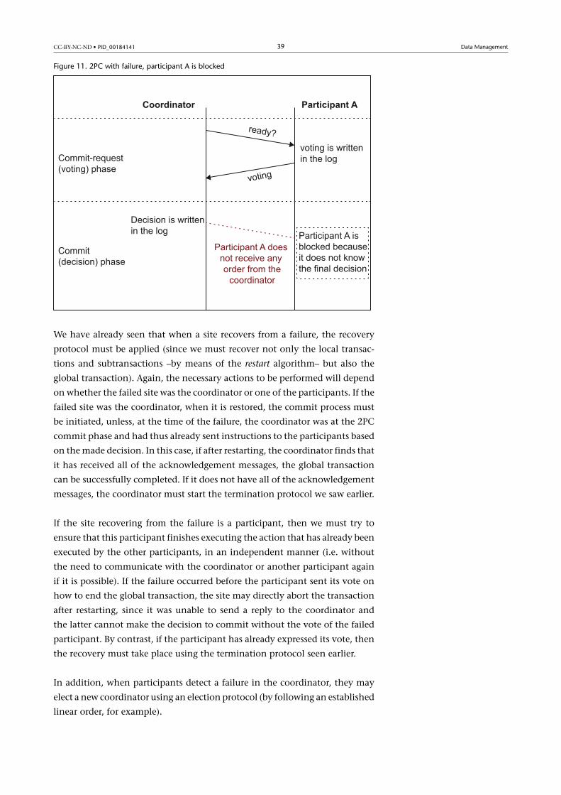
However, when a participant is waiting, the easiest option is to block the site
until communication with the coordinator can be re-established and it can
find out how to proceed (see Figure 11). Blocking has a negative impact on
the overall system performance and data availability, and compromises the
efficiency of 2PC. In an attempt to reduce the time for which a site is blocked,
the blocked site can try to contact another participant to find out the decision
made by the coordinator. This initiates the cooperative�termination�proto-
col.
Condition for thecooperative terminationprotocol
To use the cooperative termi-nation protocol, the coordina-tor must indicate to each par-ticipant which other sites areparticipating in the executionof the global transaction.
CC-BY-NC-ND • PID_00184141 39 Data Management
Figure 11. 2PC with failure, participant A is blocked
We have already seen that when a site recovers from a failure, the recovery
protocol must be applied (since we must recover not only the local transac-
tions and subtransactions –by means of the restart algorithm– but also the
global transaction). Again, the necessary actions to be performed will depend
on whether the failed site was the coordinator or one of the participants. If the
failed site was the coordinator, when it is restored, the commit process must
be initiated, unless, at the time of the failure, the coordinator was at the 2PC
commit phase and had thus already sent instructions to the participants based
on the made decision. In this case, if after restarting, the coordinator finds that
it has received all of the acknowledgement messages, the global transaction
can be successfully completed. If it does not have all of the acknowledgement
messages, the coordinator must start the termination protocol we saw earlier.
If the site recovering from the failure is a participant, then we must try to
ensure that this participant finishes executing the action that has already been
executed by the other participants, in an independent manner (i.e. without
the need to communicate with the coordinator or another participant again
if it is possible). If the failure occurred before the participant sent its vote on
how to end the global transaction, the site may directly abort the transaction
after restarting, since it was unable to send a reply to the coordinator and
the latter cannot make the decision to commit without the vote of the failed
participant. By contrast, if the participant has already expressed its vote, then
the recovery must take place using the termination protocol seen earlier.
In addition, when participants detect a failure in the coordinator, they may
elect a new coordinator using an election protocol (by following an established
linear order, for example).

CC-BY-NC-ND • PID_00184141 40 Data Management
Another relevant aspect is the communication topology used to implement
2PC. The most common topology and the one on which the above expla-
nations are based, is called centralised�2PC (since all communications pass
through the coordinator). An alternative would be to use a linear�2PC or dis-
tributed�2PC. In a linear 2PC, participants can communicate with each other,
given that a direct chain of communication is implemented from the coordi-
nator to the last participant, which deals with the voting phase, and a reverse
chain is implemented to take care of the commit phase. A distributed 2PC
keeps all sites communicated with one another. Hence, once the coordinator
has sent the commit-request (or voting) message, the participants send their
responses to all sites in the system. This way, each site can autonomously make
its own coherent decision because it has all of the responses.
5.2.2. Three-Phase Commit Protocol
As we saw in the previous section, when communication between a partici-
pant and the coordinator is lost, 2PC blocks a given site because it does not
know how to continue. Although most systems use 2PC because of the low
probability of blocking, there is an alternative protocol, namely the 3PC pro-
tocol that was one of the first attempts to resolve the blocking problems of
2PC. The 3PC protocol avoids blocking assuming a highly reliable network
(i.e. a network that never causes operational sites to be partitioned).
The basic idea of 3PC is to eliminate the uncertainty time for participants that
have voted to commit during the voting phase and are waiting for instructions
from the coordinator on how to proceed. In 3PC, a new phase is incorporated
between the commit-request (or voting) phase and the commit phase (or de-
cision), known as the pre-commit�phase. With this new phase, we ensure that
the two possible final decisions (commit or abort) for the global transaction
are not taken in the same commit protocol state (see figures 12 and 13). Thus,
whenever a participant restarts after a failure, it will know how to continue
based on its state with regard to 3PC at the time the participant failed.
When the coordinator receives the votes from all of the participants, it sends
them a global pre-commit message. A participant receiving the global pre-
commit message already knows that the other participants have voted to com-
mit and inevitably it will have to make its final commit unless it experiences
a failure. Each participant must acknowledge the receipt of the pre-commit
message. Once the coordinator has received all the pre-commit acknowledge-
ment messages, it then sends the global commit message to all participants
(see Figure 12). If some participant voted to abort during the voting phase, the
same procedure as for 2PC would be followed (see Figure 13).

CC-BY-NC-ND • PID_00184141 41 Data Management
The algorithm below indicates the actions that must be executed both by the
coordinator and the participants during the execution of 3PC. Notice how the
relevant entries (denoted as records in the algorithm) are written in the log
here too.

CC-BY-NC-ND • PID_00184141 42 Data Management
Figure 12. Three-Phase Commit Protocol, committing.

CC-BY-NC-ND • PID_00184141 43 Data Management
Figure 13. Three-Phase Commit Protocol, aborting.
Both the coordinator and the participants still have waiting periods. More im-
portantly, however, all operational sites will have been informed of the global
commit decision made by the coordinator thanks to the pre-commit message.
This means that each site can work autonomously even in the event of failure.
As in the 2PC, when time-out expires, the 3PC termination protocol must be
used. If the coordinator is waiting to receive the vote of some participant, it
may decide to abort the global transaction. If the coordinator is waiting to re-
ceive the pre-commit acknowledgement message, it may complete the global
transaction, writing the corresponding entry in the log, and send the commit
message of the global transaction to the participants. If the coordinator does
not receive a message confirming the successful execution of the commit or
abort operations, it can re-send the message with the global made decision to
the sites that have not sent the acknowledgement message.
By contrast, if some participant is waiting to receive the voting message, the
participant may decide to abort the transaction (which will cause the abort
of the global transaction). If the participant has already sent its vote to the

CC-BY-NC-ND • PID_00184141 44 Data Management
coordinator and is waiting to receive the pre-commit or the abort message,
or if the participant has sent the pre-commit acknowledgement message and
is waiting for the commit order, then the participant must use the election
protocol to select a new coordinator for the global transaction, allowing the
new coordinator to resume the commit protocol.
Again, as with 2PC, recovery protocols are important for 3PC. If the coordi-
nator fails before the commit process is initiated, then it is only necessary to
restart this process. However, if the coordinator fails while waiting for the vote
response or while awaiting the pre-commit acknowledgement message, then
the participants may have chosen a new coordinator to complete the global
transaction. In these cases, when the failed coordinator restarts, it will need to
communicate with one of the participants to determine the final state of the
global transaction. If none of the above apply, the coordinator will have failed
while waiting for the response of the participants to its instructions about the
action to be executed. In this case, once the coordinator has restarted, it will
need to check whether it has all the acknowledgement messages to complete
the global transaction properly; if it does not, it will need to initiate the ter-
mination protocol.
If the failed site is one of the participants, the participant may abort the trans-
action if voting did not take place before the failure. By contrast, if the par-
ticipant failed after the vote was delivered or after the pre-commit acknowl-
edgement message was received, once the restart process were completed, it
would have to contact another participant to find out the final state of the
global transaction. If the participant fails after the order to commit or abort
is executed, given that the participant will have already completed the trans-
action, no further action is necessary.
5.3. Data Replication
When a DDB is replicated, either partially or completely, this means that we
need to maintain the consistency of the replicas.
In this case, the problem arises when replicas of the same data are located in
different system partitions as a result of a site or a communication failure.
The only two options in a situation like this are to allow or forbid access to
the replicas that have been cut off. Both options have advantages and disad-
vantages. If we allow work on the different replicas with no communication
between the sites where they are located (following an optimistic protocol),
the replicas could end up in an inconsistent state, although obviously the
availability of the data will have increased. If, by contrast, we choose to pro-
hibit access to the replicas in the absence of communication between the sites
where they are stored (following a pessimistic protocol), availability decreases
but we guarantee the data consistency.
Note
Replicas must have exactly thesame content in order to beconsistent.

CC-BY-NC-ND • PID_00184141 45 Data Management
There is an intermediate possibility, which only applies if we have defined a
master�copy. In this case, anybody with access to the master copy can con-
tinue working, while those who only have access to the replicas will be unable
to do so.
5.4. Media Recovery
For the media recovery of a DDB in the event of a hardware failure, we must
use the same techniques as for media recovery in centralised DBs, taking into
account that the sites storing the DB must define their own backup policies.

CC-BY-NC-ND • PID_00184141 46 Data Management
Summary
In this module, we have learned how the properties of atomicity and durabil-
ity of transactions highlight the need for recovery techniques to guarantee
database consistency. We have also seen how other problems, such as hard-
ware errors, can cause loss of data, which also makes recovery techniques in-
dispensable.
The recovery manager is the most important subcomponent of the data man-
ager and deals with both logging and media recovery techniques. The purpose
of the data manager is to deal with access operations to the physical database
while ensuring the data consistency.
We have also presented the log. The log contains data that are essential for
both logging and media recovery.
With regard to logging recovery, we have seen the different policies (steal/
no steal and force/no force), being the most common one the steal/no force
policy.
We have also studied that media recovery can be done by means of backups
and logs. Another alternative is based on the use of a database mirror.
The problems that can occur in the sites or communication that form a dis-
tributed system show that, although the DBMS of each DB forming the DDB is
able to use local recovery mechanisms, it is possible that a global transaction
cannot be completed. This is why we have studied the 2PC and 3PC atomic
commit protocols.

CC-BY-NC-ND • PID_00184141 47 Data Management
Self-evaluation
1. In which situations can the total or partial loss of data stored in a DB occur?
2. Describe the operations offered by the buffer manager.
3. What is the log used for?
4. Which logging recovery manager policy minimises the number of input/output opera-tions?
5. Write an algorithm for the commit operation in a logging recovery manager that worksin no steal/no force policy.
6. How does the restart procedure differ if the transaction-consistent checkpointing is used?
7. Are backups only useful for media recovery?

CC-BY-NC-ND • PID_00184141 48 Data Management
Answer key
1. The data stored in a DB can be lost primarily as a result of a system failure and as a resultof storage device errors.
2. The buffer manager offers two operations. The fetch operation is used to read a physicalpage of the DB to a buffer slot. With the flush operation, a page is removed from a buffer slotand physically stored in the DB if changes have been made.
3. The log is used to store information on the changes made during the execution of transac-tions. This ensures that we have the necessary information to recover a consistent DB state.
4. Any manager based on the no force policy can minimise the number of input/output op-erations, since it only flushes the buffer slots when required.
5. We can know which buffer slots were assigned to a transaction if the log is read backwards.Thus, the algorithm for the commit operation can be written as follows:
Another option would be that the logging recovery manager could maintain a list of bufferslots assigned to each transaction.
6. With transaction-consistent checkpointing, we can ensure that there was no active trans-action when the checkpointing was made; we can therefore be certain that when we restartthe system, it will not be necessary to undo the changes recorded before the last checkpoint-ing (i.e. undo_complementary_phase action is not required).
7. No. Backups are useful for recovering a given state of the database, either due to loss orbecause the changes made after a certain time have generated incorrect data. With backups,we can revert to a correct state prior to the point at which the error occurred.

CC-BY-NC-ND • PID_00184141 49 Data Management
Glossary
buffer pool Volatile memory that uses the database management system to ensure anefficient access to the physical database (i.e. the persistent storage).
checkpointing Method that forces the storage of a consistent state of the database andcreates a new entry in the log.
data manager Component of the database management system that ensures an efficientand correct access to the physical database (i.e. the persistent storage).
DBMS Acronym of database management system
fetch Operation performed by the buffer manager that reads a physical page that is loadedin a buffer slot.
flush Operation performed by the buffer manager that takes a page from the buffer pooland stores it in the physical database if it has been modified.
force policy Operating policy of the logging recovery manager in which, when a transac-tion commits, the logging recovery manager forces the flushing of the buffer slots assignedto the transaction.
in-place updating Technique used when flushing buffer slots to the physical databasethat overwrites the involved pages, given that are always stored in the same place.
log Sequential file that records the history of the transactions with the changes they made.
logging recovery Term that covers all mechanisms and techniques for recovering a data-base, thereby ensuring compliance with the atomicity and durability properties of the trans-actions.
media recovery Term that includes all mechanisms and techniques for rebuilding a data-base in the event of the total or partial loss of data due to hardware errors.
mirror Secondary copy of a database used to facilitate reading and to rebuild the databasein the event of the total or partial loss of data.
no force policy Operating policy of the logging recovery manager that, when a transactioncommits, does not force the flushing of the buffer slots assigned to the transaction.
no steal policy Operating policy of the logging recovery manager in which the loggingrecovery manager does not allow the flushing of a buffer slot while the transaction usingit remains active.
recovery manager Subcomponent of the data manager in charge of implementing therecovery techniques.
shadowing Technique used for flushing buffer slots to the physical database that searchesfor a new space every time a page has to be saved; it therefore keeps the previous page version.
steal policy Operating policy of the logging recovery manager in which the logging re-covery manager allows the flushing of a buffer slot even though the transaction using itremains active.
Three-phase commit (3PC) Synchronisation protocol that ensures the global atomicityof distributed transactions while alleviating the blocking aspect of 2PC in the event of sitefailures. In other words, 3PC never requires operational sites to wait (i.e. block) until a failedsite has recovered.
Two-phase commit (2PC) Synchronisation protocol that solves the atomic commitmentproblem. It is used in distributed database systems to ensure the global atomicity of transac-tions in spite of site and communication failures, assuming that a failure will eventually berepaired and each site guarantees the atomicity of transactions at local level.
Write-ahead logging protocol Protocol that specifies how and when to make log entries.

CC-BY-NC-ND • PID_00184141 50 Data Management
Bibliography
Bernstein, P. A.; Hadzilacos, V.; Goodman, N. (1987). Concurrency Control and Recoveryin Database Systems. Reading (Massachusetts): Addison-Wesley.
Connolly, T.; Begg, C. (2009). Database Systems. A Practical Approach to Design, Implemen-tation, and Management.(5th edition) Harlow (England): Addison-Wesley.
Elmasri, R.; Navathe, S. B. (2007). Fundamentals of Database Systems (5th edition). Boston(Pearson): Addison-Wesley.
Garcia-Molina, H.; Ullman, J. D.; Widom, J. (2009). Database Systems. The CompleteBook (2nd Edition). Pearson – Prentice Hall.
Liu, L.; Özsu, M. T. (Eds.) (2009). Encyclopedia of Database Systems. Springer.
McFadden, F. R; Hoffer, J. A.; Prescott, M. B. (1999). Modern Database Management.Reading (Massachusetts): Addison-Wesley.
Ramakrishnan, R. (1998). Database Management Systems. Boston (Massachusetts): Mc-Graw-Hill.