architectural exploration of digital systems design for
TRANSCRIPT

UNIVERSIDADE FEDERAL DO RIO GRANDE DO SULINSTITUTO DE INFORMÁTICA
PROGRAMA DE PÓS-GRADUAÇÃO EM COMPUTAÇÃO
JEFERSON SANTIAGO DA SILVA
Architectural Exploration of DigitalSystems Design for FPGAs Using
C/C++/SystemC Specification Languages
Thesis presented in partial fulfillmentof the requirements for the degree ofMaster in Computer Science
Prof. Dr. Sergio BampiAdvisor
Porto Alegre, January 2015

CIP – CATALOGING-IN-PUBLICATION
da Silva, Jeferson Santiago
Architectural Exploration of Digital Systems Design for FP-GAs Using C/C++/SystemC Specification Languages / JefersonSantiago da Silva. – Porto Alegre: PPGC da UFRGS, 2015.
83 f.: il.
Thesis (Master) – Universidade Federal do Rio Grande do Sul.Programa de Pós-Graduação em Computação, Porto Alegre, BR–RS, 2015. Advisor: Sergio Bampi.
1. High-level Synthesis. 2. FPGA. 3. Design Space Explo-ration. 4. Digital Design. 5. Optimization Techniques. I. Bampi,Sergio. II. Architectural Exploration of Digital Systems Designfor FPGAs Using C/C++/SystemC Specification Languages.
UNIVERSIDADE FEDERAL DO RIO GRANDE DO SULReitor: Prof. Carlos Alexandre NettoVice-Reitor: Prof. Rui Vicente OppermannPró-Reitor de Pós-Graduação: Prof. Vladimir Pinheiro do NascimentoDiretor do Instituto de Informática: Prof. Luís da Cunha LambCoordenador do PPGC: Prof. Luigi CarroBibliotecária-chefe do Instituto de Informática: Beatriz Regina Bastos Haro

“Best remain silent and be thought a fool,than open your mouth and remove all doubt.”
— ABRAHAM LINCOLN

ACKNOWLEDGMENTS
I would like to thank all my family, specially to my wife Clara. I want to thankProf. Bampi, my advisor in this work. My thanks also go to all staff of PPGC, includingprofessors and administrative personnel.

ABSTRACT
The increasing demand for high computational performance and massive data pro-cessing has driven the development of systems-on-chip. One implementation target forcomplex digital systems are FPGA (Field-programmable Gate Array) devices, heavilyused for prototyping systems or complex and fast time-to-market electronic products de-velopment. Certain inefficient aspects of FPGA devices relate to performance and powerdegradation with respect to custom hardware design.
In this context, this master thesis proposes a survey on FPGA optimization techniques.This work presents a literature review on methods of power and area reduction appliedto FPGA designs. Techniques for performance increasing and design speedup enhancingwill be presented based on classic and state-of-the-art academic works. The main focusof this work is to discuss high-level design techniques and to present the results obtainedin synthesis examples we developed, comparing with hand-coded HDL (Hardware De-scription Language) designs.
In this work we present our methodology for fast digital design development usingHigh-Level Synthesis (HLS) environments. Our methods include efficient high-levelcode partitioning for proper synthesis directives exploration in HLS tools. However, anon-guided HLS flow showed poor synthesis results when compared to hand-coded HDLdesigns. To fill this gap, we developed an iterative design space exploration method aim-ing at improving the area results. Our method is described in a high-level script languageand it is compatible with the Xilinx VivadoTM HLS compiler. Our method is capable ofdetecting optimization checkpoints, automatic synthesis directives insertion, and checkthe results aiming at reducing area consumption.
Our Design Space Exploration (DSE) experimental results proved to be more efficientthan non-guided HLS design flow by at least 50% for a VLIW (Very Long InstructionWord) processor and 62% for a 12th-order FIR (Finite Impulse Response) filter imple-mentation. Our area results in terms of flip-flops were up to 4X lower compared to anon-guided HLS flow, while the performance overhead was around 38%, for the VLIWprocessor compilation. In the FIR filter example, the flip-flops reduction were up to 3X,with no relevant LUTs and performance overhead.
Keywords: High-level Synthesis, FPGA, Design Space Exploration, Digital Design, Op-timization Techniques.

RESUMO
Exploração Arquitetural no Projeto de Sistemas Digitais para FPGAs UtilizandoLinguagens de Especificação C/C++/SystemC
A crescente demanda por alto desempenho computacional e massivo processamentode dados tem impulsionado o desenvolvimento de sistemas-on-chip. Um dos alvos de im-plementação para sistemas digitais complexos são os dispositivos FPGA (Field-programmableGate Array), muito utilizados para prototipação de sistemas e rápido desenvolvimento deprodutos eletrônicos complexos. Certos aspectos ineficientes relacionados aos dispositi-vos FPGA estão relacionadas com degradação no desempenho e na potência consumidaem relação ao projeto de hardware customizado.
Neste contexto, esta dissertação de mestrado propõe um estudo sobre técnicas de oti-mização em FPGAs. Este trabalho apresenta uma revisão da literatura sobre os métodosde redução de potência e área aplicados ao projeto de FPGA. Técnicas para aumentode desempenho e aceleração do tempo de desenvolvimento de projetos são apresentadascom base em referencias clássicas e do estado-da-arte. O principal foco deste trabalhoé discutir sobre as técnicas de alto nível e apresentar os resultados obtidos nesta área,comparando com os projetos HDL (Hardware Description Language) codificados a mão.
Neste trabalho, é apresentado uma metodologia para o desenvolvimento rápido pro-jetos digitais utilizando ambientes HLS (High-Level Synthesis. Estes métodos incluemeficiente particionamento de código de alto nível, para a correta exploração de diretivasde síntese em ferramentas HLS. Porém, o fluxo HLS não guiado apresentou pobres resul-tados de síntese quando comparado com modelos HDL codificado a mão. Para preencheressa lacuna, foi desenvolvido um método iterativo para exploração de espaço de projetocom o objetivo de melhorar os resultados de área. Nosso método é descrito em umalinguagem de script de alto nível e é compatível com o VivadoTM HLS Compiler. O mé-todo proposto é capaz de detectar pontos chave para otimização, inserção automatica dediretivas síntese e verificação dos resultados com objetivo de reduzir o consumo de área.
Os resultados experimentais utlizando o método de DSE (Design Space Exploration)provaram ser mais eficazes que o fluxo HLS não guiado, em ao menos 50% para umprocessador VLIW e em 43% para um filtro FIR (Finite Impulse Response de 12a ordem.Os resultados em área, em termos de flip-flops, foram até 4X menores em comparaçãocom o fluxo HLS não guiado, enquanto redução no desempenho ficou em cerca de 38%,no caso do processador VLIW. No exemplo do filtro FIR, a redução no número flip-flopschegou a 3X, sem relevante aumento no número de LUTs e redução no desempenho.
Palavras-chave: Síntese de Alto Nível, FPGA, Exploração de Espaço de Projeto, Siste-mas Digitais, Técnicas de Otimização.

LIST OF ABBREVIATIONS AND ACRONYMS
ABEL Advanced Boolean Expression Language
ABL A Block diagram Language
ALU Arithmetic and Logic Unit
ANSI American National Standards Institute
APL A Programming Language
ASIC Application-Specific Integrated Circuit
CE Clock Enable
CMOS Complementary Metal-Oxide-Semiconductor
CT Compute Time
CPU Central Processing Unit
CUDA Compute Unified Device Architecture
DSE Design Space Exploration
DDDG Dynamic Data Dependence Graphs
DSP Digital Signal Processing
EDA Electronic Design Automation
FF Flip-flop
FIR Finite Impulse Response
FPGA Field-Programmable Gate Array
FSM Finite State Machine
GIMP GNU Image Manipulation Program
GPU Graphic Processing Unit
HDL Hardware Description Language
HLS High-Level Synthesis
HW Hardware
IC Integrated Circuit
IEEE Institute of Electrical and Electronics Engineers
ISP Instruction Set Processing
JPEG Joint Photographic Experts Group
LDMC Logic Delay Measurement Circuit
KARL Kaiserslautern RTL
LE Logic Element
LUT Look-up Table
MAC Multiply and Accumulate
MIPS Microprocessor without Interlocked Pipeline Stages
MPEG Moving Picture Experts Group
OpenCL Open Computing Language
PLL Phase-locked loop
QoR Quality of Results
RAM Random Access Memory
RISC Reduced Instruction Set Computer
RTL Register-Transfer Level
SDK Software Development Kit
SRAM Static RAM
SW Software
TCL Tool Command Language
Vex VLIW Example
VLIW Very Long Instruction Word
VHDL VHSIC HDL
VHSIC Very-High-Speed IC

LIST OF SYMBOLS
α Switching Rate
C Capacitance
f Operation Frequency
Vdd Power-Supply Voltage
τDN Wire Delay
L Wire Length
c Capacitance of a Wire per Unit Area
r Sheet Resistance of a Wire (Ω/square)
ρ-Vex Reconfigurable Vex Processor

LIST OF FIGURES
1.1 Typical FPGA Scheme. . . . . . . . . . . . . . . . . . . . . . . . . . 151.2 Classic FPGA Design Flow. . . . . . . . . . . . . . . . . . . . . . . 17
2.1 Resource Sharing. a) Behavioural description. b) Data and ControlPath. c) Data and Control Path with Sum/Sub Operations Merged . . 19
2.2 Internal Architecture of a FPGA Logic Element inside VirtexTM 5. . . 202.3 Gated Clock Circuits: a) Falling edge. b) Rising edge. . . . . . . . . 212.4 LDCM scheme proposed in (CHOW et al., 2005). . . . . . . . . . . . 222.5 Four issue VLIW scheme. . . . . . . . . . . . . . . . . . . . . . . . 222.6 Fan-out Reduction Circuit (N = 2). . . . . . . . . . . . . . . . . . . . 23
3.1 Verilog Implementation for a D-FF. . . . . . . . . . . . . . . . . . . 263.2 VHDL Implementation for a D-FF. . . . . . . . . . . . . . . . . . . 273.3 SystemC Implementation for a D-FF. . . . . . . . . . . . . . . . . . 273.4 SPARK Design Flow. . . . . . . . . . . . . . . . . . . . . . . . . . . 303.5 LOPASS Design Flow. . . . . . . . . . . . . . . . . . . . . . . . . . 313.6 LegUp Design Flow. . . . . . . . . . . . . . . . . . . . . . . . . . . 323.7 FIR Filter Design Space Exploration. . . . . . . . . . . . . . . . . . 343.8 Loop Unrolling. a) Loop Pseudo-code. b) Unrolled Data Flow. c)
Tree Reduction Structure. . . . . . . . . . . . . . . . . . . . . . . . 353.9 Kernel Graph. R represents a memory reading while VR represents
an variable latency for an external memory access. . . . . . . . . . . 35
4.1 Pareto Curve. . . . . . . . . . . . . . . . . . . . . . . . . . . . . . . 374.2 DSE methodology by Xydis. . . . . . . . . . . . . . . . . . . . . . . 384.3 Tuned and Untuned C code comparison. . . . . . . . . . . . . . . . . 39
5.1 Code transformation example: Original code, on left. On right, codepartitioned. . . . . . . . . . . . . . . . . . . . . . . . . . . . . . . . 41
5.2 Code Snippet Example of a VLIW Implementaion. . . . . . . . . . . 415.3 DSE Framework Flow. . . . . . . . . . . . . . . . . . . . . . . . . . 435.4 Example Code for ALU operation. . . . . . . . . . . . . . . . . . . . 44
6.1 Square Root Algorithm Pseudo-code. . . . . . . . . . . . . . . . . . 486.2 FIR Filter Pseudo-code. . . . . . . . . . . . . . . . . . . . . . . . . 506.3 DSE Area Results with VivadoTM. . . . . . . . . . . . . . . . . . . . 526.4 DSE Performance Results with VivadoTM. . . . . . . . . . . . . . . . 536.5 Multiple Size FIR Filters. a) Area Versus Filter Size Curve. b) Per-
formance Versus Filter Size Curve. . . . . . . . . . . . . . . . . . . 56

LIST OF TABLES
3.1 Hardware Design Domains and Abstraction Levels. . . . . . . . . . . 283.2 Differences between C/C++ and SystemC. . . . . . . . . . . . . . . 30
6.1 MIPS Implementation Comparison. . . . . . . . . . . . . . . . . . . 476.2 Square Root Algorithm Implementation Comparison. . . . . . . . . . 486.3 ρ-Vex Synthesis Results Using LegUp Compiler. . . . . . . . . . . . 496.4 ρ-Vex Synthesis Results Using VivadoTM HLS. . . . . . . . . . . . . 496.5 Synthesis Results for FIR Filter Example: Target Altera CycloneTM IV. 506.6 Synthesis Results for FIR Filter Example: Target Xilinx SpartanTM 6
and Xilinx VirtexTM II. . . . . . . . . . . . . . . . . . . . . . . . . . 516.7 DSE Framework Results: VLIW processor. . . . . . . . . . . . . . . 546.8 DSE Framework Results: FIR Filter. . . . . . . . . . . . . . . . . . . 556.9 Synthesis Results for Multiple Order FIR Filter Example. . . . . . . . 55

CONTENTS
1 INTRODUCTION . . . . . . . . . . . . . . . . . . . . . . . . . . . . . . 141.1 Motivation . . . . . . . . . . . . . . . . . . . . . . . . . . . . . . . . . . 151.2 Contributions . . . . . . . . . . . . . . . . . . . . . . . . . . . . . . . . . 161.3 Thesis Organization . . . . . . . . . . . . . . . . . . . . . . . . . . . . . 16
2 HARDWARE DESIGN OPTIMIZATION TECHNIQUES . . . . . . . . . 182.1 Area Saving Methods . . . . . . . . . . . . . . . . . . . . . . . . . . . . . 182.2 Power Saving Methods . . . . . . . . . . . . . . . . . . . . . . . . . . . . 182.3 Performance Enhancing Methods . . . . . . . . . . . . . . . . . . . . . . 212.4 Hardware Optimization Methods Summary . . . . . . . . . . . . . . . . 23
3 METHODS TO REDUCE DESIGN TIME . . . . . . . . . . . . . . . . . 253.1 Evolution of Hardware Description Languages . . . . . . . . . . . . . . 253.2 High-Level Synthesis Tools . . . . . . . . . . . . . . . . . . . . . . . . . 283.3 High-level Optimization Techniques . . . . . . . . . . . . . . . . . . . . 323.4 HLS tools and Methods Summary . . . . . . . . . . . . . . . . . . . . . 34
4 DESIGN SPACE EXPLORATION IN HARDWARE SYSTEMS . . . . . 364.1 Introduction . . . . . . . . . . . . . . . . . . . . . . . . . . . . . . . . . . 364.2 Architectural Exploration . . . . . . . . . . . . . . . . . . . . . . . . . . 364.3 Conclusions . . . . . . . . . . . . . . . . . . . . . . . . . . . . . . . . . . 39
5 METHODOLOGY PROPOSED FOR ARCHITECTURAL EXPLORATION 405.1 High-Level Code Tuning . . . . . . . . . . . . . . . . . . . . . . . . . . . 405.2 Iterative Design Space Exploration Method with High-level Synthesis . 425.2.1 High-level Design Entry . . . . . . . . . . . . . . . . . . . . . . . . . . . 425.2.2 High-Level Parsing . . . . . . . . . . . . . . . . . . . . . . . . . . . . . 425.2.3 Design Constraints . . . . . . . . . . . . . . . . . . . . . . . . . . . . . 445.2.4 Update HLS Directives . . . . . . . . . . . . . . . . . . . . . . . . . . . 445.2.5 Results Parsing and Analysis . . . . . . . . . . . . . . . . . . . . . . . . 455.3 Methodology Summary . . . . . . . . . . . . . . . . . . . . . . . . . . . 45
6 HIGH-LEVEL SYNTHESIS EXPERIMENTS . . . . . . . . . . . . . . . 466.1 High-Level Synthesis Tools and Design Methods Comparison Results . . 466.1.1 MIPS processor . . . . . . . . . . . . . . . . . . . . . . . . . . . . . . . 466.1.2 32 bit Integer Square Root Algorithm . . . . . . . . . . . . . . . . . . . . 476.1.3 VLIW Processor . . . . . . . . . . . . . . . . . . . . . . . . . . . . . . . 486.1.4 12th-order FIR Filter . . . . . . . . . . . . . . . . . . . . . . . . . . . . . 49

6.2 Design Space Exploration Results . . . . . . . . . . . . . . . . . . . . . . 516.2.1 Interactive DSE Results . . . . . . . . . . . . . . . . . . . . . . . . . . . 516.2.2 Iterative DSE Method Results . . . . . . . . . . . . . . . . . . . . . . . . 53
7 CONCLUSIONS . . . . . . . . . . . . . . . . . . . . . . . . . . . . . . . 57
REFERENCES . . . . . . . . . . . . . . . . . . . . . . . . . . . . . . . . . . 59
APPENDIX A RESUMO DA DISSERTAÇÃO "ARCHITECTURAL EXPLO-RATION OF DIGITAL SYSTEMS DESIGN FOR FPGAS US-ING C/C++/SYSTEMC SPECIFICATION LANGUAGES" . . 63
A.1 Introdução . . . . . . . . . . . . . . . . . . . . . . . . . . . . . . . . . . 63A.1.1 Motivação . . . . . . . . . . . . . . . . . . . . . . . . . . . . . . . . . . 64A.1.2 Contribuições . . . . . . . . . . . . . . . . . . . . . . . . . . . . . . . . 64A.1.3 Organização da Dissertação . . . . . . . . . . . . . . . . . . . . . . . . . 65A.2 Resumo das Contribuições da Dissertação: Exploração Arquitetural no
Projeto de Sistemas Digitais para FPGAs Utilizando Linguagens de Es-pecificação C/C++/SystemC . . . . . . . . . . . . . . . . . . . . . . . . . 65
A.3 Conclusões . . . . . . . . . . . . . . . . . . . . . . . . . . . . . . . . . . 66
APPENDIX B VLIW PROCESSOR SOURCE CODES . . . . . . . . . . . . 68B.1 C-code Design Entry . . . . . . . . . . . . . . . . . . . . . . . . . . . . . 68B.1.1 Constants Definitions (r_vex.h) . . . . . . . . . . . . . . . . . . . . . . . 68B.1.2 Instruction Memory (r_vex_imem.h) . . . . . . . . . . . . . . . . . . . . 71B.1.3 Branches and Memory Access Functions (r_vex_fun.h) . . . . . . . . . . 72B.1.4 Functions Prototype (r_vex_top.h) . . . . . . . . . . . . . . . . . . . . . 73B.1.5 ρ-Vex Processor Core (r_vex_top.c) . . . . . . . . . . . . . . . . . . . . 73B.1.6 ρ-Vex Processor Testbench (r_vex_tb.h) . . . . . . . . . . . . . . . . . . 82B.2 Synthesis Directives Generated by DSE Script (directives.tcl) . . . . . . 83

14
1 INTRODUCTION
FPGA devices are widely used for faster implementation of digital functions in hard-ware and for ASIC (Application-Specific Integrated Circuit) emulation. However, evenstate-of-the-art FPGAs have serious limitations in terms of performance, area utilizationand power consumption. With the increasing complexity of digital systems, optimizationtechniques must be performed to make digital projects with these devices competitive.
In this work we discuss the most common techniques available in the literature target-ing FPGA design optimization. These methods include power savings such techniquesas clock gating and frequency/voltage scaling. In terms of area, we will discuss the im-portance of resource sharing. For performance enhancing, techniques such as pipelining,parallelism and fan-out reduction will be reviewed.
The main purpose of this master thesis is to discuss and to explore high-level designoptimization techniques applied to FPGA systems. The Register-Transfer Level (RTL)design is the project schedule bottleneck in digital systems design. HLS (High-LevelSynthesis) methods and utilization will be discussed for fast turn-around purpose. Com-mercial and academic HLS tools will be presented, as well as, advanced design techniquesusing high-level specification languages, for example C/C++ or SystemC.
Many algorithm standards are open-source available in high-level languages, such asC. In the classic FPGA design flow, hardware designers must to translate these algo-rithms onto FPGA hardware performing all steps of optimization using register-transferlevel languages. RTL development and verification is a complex and expensive task whencompared to software implementations. Higher level abstractions allow software design-ers to develop FPGA hardware using HLS compilers. HLS tool providers affirm that forthe certain test-cases, the productivity can be increased up to 50% using HLS methodscompared to hand-coded RTL design. The addition of directives/pragmas in the HLScompilers allows the designers to guide the algorithm implementation for a specific de-sign trade-off, for example, performance or area reduction. The verification process in aRTL based flow is very hard due to limitations of HDL languages in describing the realworld circuit behaviour, while using higher abstraction languages it is possible to emulatethe operation conditions. Moreover, a RTL simulation can take several hours, even daysdepending of circuit complexity, which normally requires powerful simulation servers.
In this context, this work presents a methodology for digital design using high-levellanguages through HLS design flow. We explore techniques of code partitioning andpragmas insertion targeting Quality of Results (QoR) improvement. In our work, wedeveloped an iterative method for wide design space exploration with HLS aiming at areareduction. Our method proves to be very effective when compared to a non-guided HLSdesign flow, being up to 50% more efficient, using an academic VLIW processor as designbenchmark.

15
1.1 Motivation
The FPGA is a pre-defined chip, which contains a large number of macro-cells, in-terconnected with each other by routing wires and routing switches. Each macro-cell hasinside a programmable input multiplexer logic which is capable to implement all possi-ble logic equations of its inputs combinations and a storage element (flip-flop). ModernFPGA devices include RAM (Random Access Memory) blocks, DSP (Digital Signal Pro-cessing) blocks, PLLs (Phase-locked loop), gigabit transceivers and even embedded hardprocessors. Figure 1.1 illustrates a typical FPGA diagram.
Figure 1.1: Typical FPGA Scheme.
Source: Xilinx, Inc.
According to data from the FPGA vendors, normally more than 70% of the silicon areaof an FPGA is destined to interconnections, which makes these devices very inefficientin terms of area consumption. As a pre-defined silicon wafer, the power consumption is aproblem, because the power leakage component is always present in the entire chip, evenif its logic cells and flip-flops are not used. In terms of dynamic power, the major vendorsof FPGA have made a hard effort to make these devices more efficient. Hard components- like blocks of SRAM (Static Random Access Memory) and DSPs - also consume power,but these components optimization methods and utilization will not be discussed in thiswork.
The performance in FPGAs is worse than in ASIC devices. While ASICs are designedtargeted to a specific application, FPGAs are generic and this impacts directly the timingissues. Many logic levels between storage elements, large fan-outs, the clock tree, the wiredelay - including nets and routing switches - and fixed logic element placement contributeto decreasing of maximum operation frequency.
The hardware development is high cost and takes a large fraction of design time. Thetraditional FPGA development is based on system level architecture, RTL description,functional simulation and at end, logical synthesis and place and routing. In this method,the hardest task is the RTL description, normally a slow and meticulous task. Advanced

16
HLS techniques automate task, generating a synthesizable RTL code from a high-levellanguage. Figure 1.2 shows the classic design flow. Recent efforts in HLS research havemade the high-level systems design competitive for FPGA-based systems. Regular archi-tectures, such as those DSP algorithms, are normally present in works in the literatureto evaluate the high-level implementations. Algorithm scheduling, loop/function pipelin-ing, parallelism and loop unrolling are common techniques used by HLS tools providersaiming at results improvement.
Even with HLS tools enhancement in recent years, some designs still difficult to obtaingood synthesis results. Irregular architectures and control based algorithms, for instance,have limited synthesis results comparing to the hand-coded HDL designs. In this context,it is necessary to develop architectural design exploration for these designs, providing thenecessary adaptations in the design entry code and to explore efficiently the HLS compilerparameters.
1.2 Contributions
The main contribution of this master thesis is to propose high-level exploration tech-niques for digital systems design targeted to FPGA devices. The main contributions ofthis work are listed below:
• High-level Architectural Exploration: to achieve good synthesis results withhigh-level descriptions it is necessary some code improvements. We discuss in ourmethodology some techniques used in HLS environments. We propose an efficientcode partitioning combined with appropriate HLS compilation directives/pragmasaiming at synthesis results improvement. Our experiments addressed two HLStools: the LegUp compiler and the VivadoTM HLS compiler.
• Design Space Exploration Method with High-level Synthesis: addressing higherQuality of Results in the HLS environment, we proposed an iterative method forDSE of hardware systems. Our method is multi-platform, it is written in Lua lan-guage (LUA, 2014) and it is compatible with VivadoTM HLS compiler. This methodis basically composed of these steps: high-level code parsing and analysis, auto-matic compilation directives insertion and results evaluation.
1.3 Thesis Organization
This master thesis is organized as follows: Hardware optimization techniques andmethods are reviewed in Chapter 2. In this chapter, we discuss about well-known method-ologies for design optimization in terms of area, power and performance for FPGAs. HLStools and methods are revisited in Chapter 3, presenting the evolution of HDL languagesand the state-of-the-art HLS tools and the known HLS optimization methods availablein the literature. Design Space Exploration in hardware systems is presented in Chap-ter 4, where are introduced important concepts for high-efficient DSE applied to hard-ware design. In the Chapter 5 we present our methodology for this work, which includeshigh-level code tuning and an iterative DSE method with HLS. Chapter 6 presents ourexperimental results, for both HLS tools comparison and DSE methodology in a HLSenvironment. Finally, the conclusions of this work are drawn in the Chapter 7.

17
Figure 1.2: Classic FPGA Design Flow.
Source: the author.

18
2 HARDWARE DESIGN OPTIMIZATION TECHNIQUES
FPGA devices are known for being very inefficient in terms of power consumption,useful silicon area and performance, when compared to equivalent dedicated ASIC de-vices. Over the last decades, researchers have addressed much effort to make this designflow more competitive compared to ASICs. Clock enable and clock gating methods havedriven the power reduction techniques in recent years. Deep pipelines and hardware par-allelism are widely used targeting performance increasing in FPGAs. For area purposes, awell known method is resource sharing combined with efficient scheduling mechanisms.
In this context, this chapter will discuss design techniques applied to FPGA-basedsystems. These methods address different design trade-offs. Area saving techniques,power reduction methods and performance optimization methods are presented accordingto state-of-the-art literature.
2.1 Area Saving Methods
EDA (Electronic Design Automation) tools from FPGA providers have in their de-sign suites, many synthesis options for area saving purpose. These options include reg-ister sharing, equivalent registers removal, hierarchy destruction and FSM (Finite StateMachine) extraction into RAMs.
In the literature, a common area saving method is the resource sharing/re-utilization.Figure 2.1 shows an illustration of the resource sharing method proposed in (RAJE;BERGAMASCHI, 1997). This technique includes the optimal component placement andtask scheduling allowing efficient resource sharing (SUN; WIRTHLIN; NEUENDORF-FER, 2007).
2.2 Power Saving Methods
As in ASIC design, frequency scaling is a common power saving technique when wetalk about FPGA design. Many works present in the literature illustrates the good resultsin terms of power reduction using frequency scaling. One method applied to synchronoussystem is the clock enable. All modern FPGAs have a clock enable pin in their flip-flops.This pin is used to perform the clock enable technique in FPGA devices. Figure 2.2illustrates a typical LE (Logic Element) of an FPGA device.
When CE (Clock Enable) is asserted, the storage element in the FPGA LE works ex-actly like the D-type FF (Flip-flop). When the CE pin is setted to 0, the clock source isdisabled in the flip-flop and the outputs do not change their logic states. According Equa-tion 2.1, the dynamic power in a CMOS (Complementary Metal-Oxide-Semiconductor)

19
Figure 2.1: Resource Sharing. a) Behavioural description. b) Data and Control Path. c)Data and Control Path with Sum/Sub Operations Merged
Source: (RAJE; BERGAMASCHI, 1997).
circuit is a function, between others parameters, of the switching rate:
Pdyn = CV 2ddfα (2.1)
where Pdyn is the dynamic power, C represents the capacitance, Vdd represents the supplyvoltage and α is the switching rate. If CE pin is not asserted the dynamic power goes to 0.However, the clock enable method reduces power only in the flip-flop and combinational

20
Figure 2.2: Internal Architecture of a FPGA Logic Element inside VirtexTM 5.
Source: Xilinx, Inc.
logic, being not effective in the clock tree.On the other hand, the clock gating technique is independent from FPGA technology
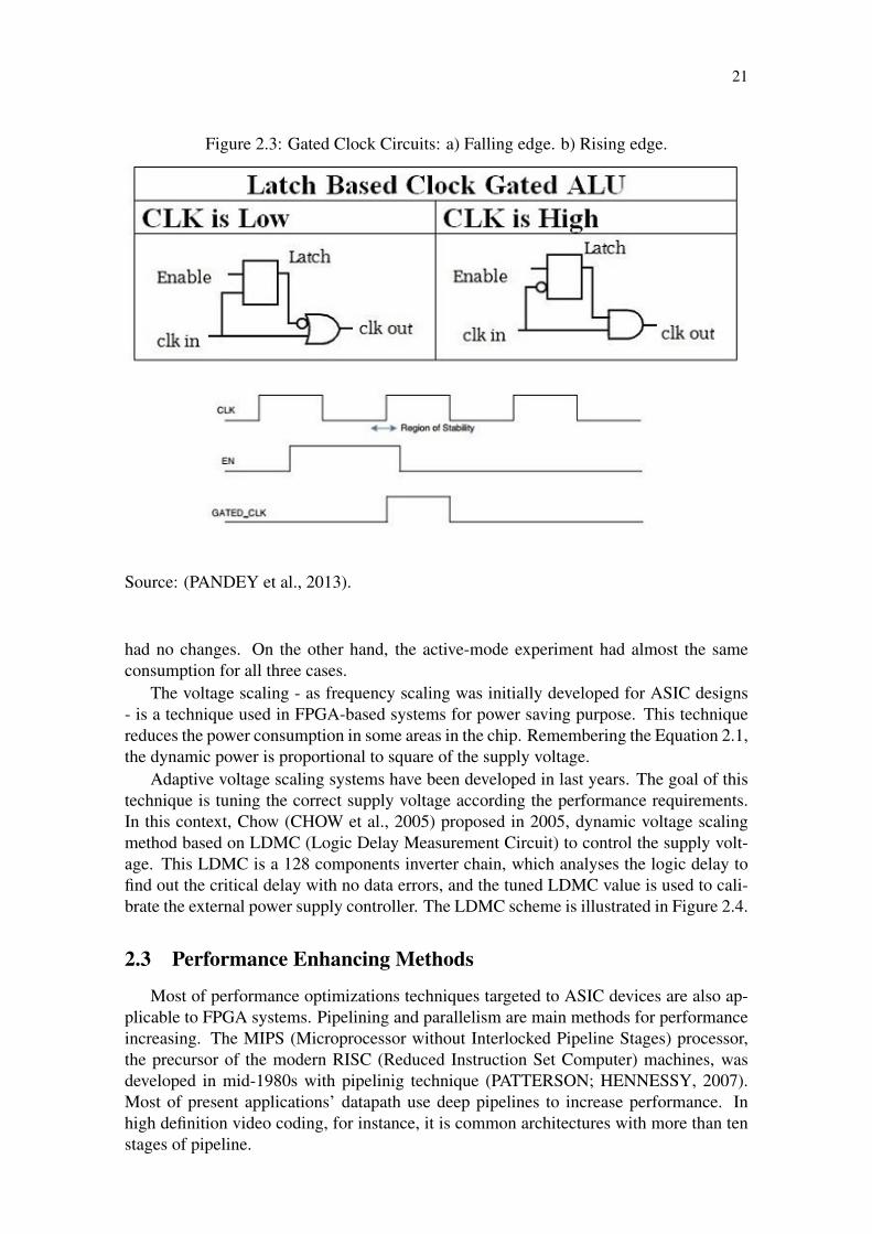
and optimize power consumption, including in the clock tree. This method is performedusing simple circuits, according to clock polarity. Many works have been presented inrecent years considering this topic. (ZHANG; ROIVAINEN; MAMMELA, 2006), pre-sented in 2006 a comparative study between FPGA and ASIC clock gating. His experi-ments suggest good results for dynamic power reduction in FPGAs, compared to ASIC,however this power reduction is insignificant because of static FPGA power consumption.Huda presented in 2009 (HUDA; MALLICK; ANDERSON, 2009), a clock-gating tech-nique based on efficient FPGA clock region division and a placement algorithm. Pandeyproposes in (PANDEY et al., 2013), two latch-based gated clock generator, as shown inFigure 2.3. The gated clock generated by the circuits drives the registers and it controlsthe global reset for an ALU (Arithmetic and Logic Unit).
In 2012, Oliver presented in (OLIVER et al., 2012), a comparative study betweenthree power saving techniques, two of them, clock-enable and clock gating, were alreadypreviously discussed. The other technique used in his work was the inputs blocking. Itwas made implementing a kind of latch, which is enabled with the CE pin of FPGA LE.In his results section it was clear the impact of clock tree on power consumption, becausein standby-mode, the clock-enable and inputs blocking techniques had power increasingwith enlarging circuits, while using the clock gating technique the power consumption
21
Figure 2.3: Gated Clock Circuits: a) Falling edge. b) Rising edge.
Source: (PANDEY et al., 2013).
had no changes. On the other hand, the active-mode experiment had almost the sameconsumption for all three cases.
The voltage scaling - as frequency scaling was initially developed for ASIC designs- is a technique used in FPGA-based systems for power saving purpose. This techniquereduces the power consumption in some areas in the chip. Remembering the Equation 2.1,the dynamic power is proportional to square of the supply voltage.
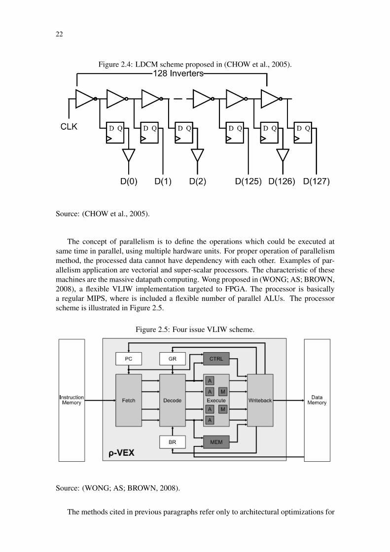
Adaptive voltage scaling systems have been developed in last years. The goal of thistechnique is tuning the correct supply voltage according the performance requirements.In this context, Chow (CHOW et al., 2005) proposed in 2005, dynamic voltage scalingmethod based on LDMC (Logic Delay Measurement Circuit) to control the supply volt-age. This LDMC is a 128 components inverter chain, which analyses the logic delay tofind out the critical delay with no data errors, and the tuned LDMC value is used to cali-brate the external power supply controller. The LDMC scheme is illustrated in Figure 2.4.
2.3 Performance Enhancing Methods
Most of performance optimizations techniques targeted to ASIC devices are also ap-plicable to FPGA systems. Pipelining and parallelism are main methods for performanceincreasing. The MIPS (Microprocessor without Interlocked Pipeline Stages) processor,the precursor of the modern RISC (Reduced Instruction Set Computer) machines, wasdeveloped in mid-1980s with pipelinig technique (PATTERSON; HENNESSY, 2007).Most of present applications’ datapath use deep pipelines to increase performance. Inhigh definition video coding, for instance, it is common architectures with more than tenstages of pipeline.
22
Figure 2.4: LDCM scheme proposed in (CHOW et al., 2005).
Source: (CHOW et al., 2005).
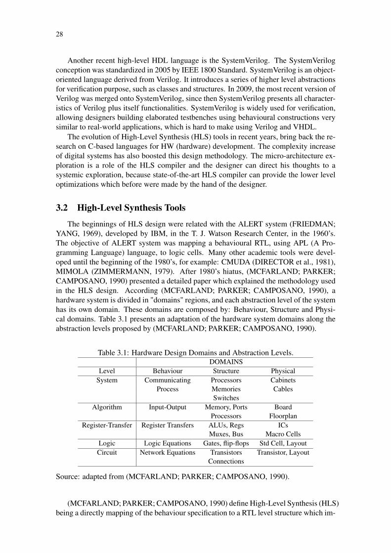
The concept of parallelism is to define the operations which could be executed atsame time in parallel, using multiple hardware units. For proper operation of parallelismmethod, the processed data cannot have dependency with each other. Examples of par-allelism application are vectorial and super-scalar processors. The characteristic of thesemachines are the massive datapath computing. Wong proposed in (WONG; AS; BROWN,2008), a flexible VLIW implementation targeted to FPGA. The processor is basicallya regular MIPS, where is included a flexible number of parallel ALUs. The processorscheme is illustrated in Figure 2.5.
Figure 2.5: Four issue VLIW scheme.
Source: (WONG; AS; BROWN, 2008).
The methods cited in previous paragraphs refer only to architectural optimizations for

23
FPGA devices. Others techniques address how is possible to deal the technology charac-teristics, such as long wires in CMOS circuits, which could represent a bad design guidein a performance-oriented system. The Equation 2.2 (RABAEY; CHANDRAKASAN;NIKOLIC, 2003) associates the wire length and specific resistance/capacitance. The re-lation between net delay and wire length is quadratic, then the wire increasing means adrastic frequency reduction:
τDN =rcL2
2(2.2)
where τDN represents the wire delay, r is the specific resistance per square, c is the ca-pacitance per unit area, and L is the wire length.
The fan-out reduction technique could be useful to reduce long wires and wire capac-itance. One known method of fan-out control is based on a binary tree. Its a register-oriented technique and each FF has maximum of two internal register fan-out. The num-ber of output is 2N with latency N. The area overhead of this fan-out reducing proposal is∑N−1
i=0 2i. Figure 2.6 shows a typical circuit for a factor 2 fan-out reduction.
Figure 2.6: Fan-out Reduction Circuit (N = 2).
Source: the author.
2.4 Hardware Optimization Methods Summary
The methods discussed in previous sections are a few of possible techniques availableon a large digital design optimization universe. In the last 50 years, several other tech-niques were presented in the literature and all possible techniques cannot be presented insingle work.
In this chapter, we revisited the most known area saving methods, as resource shar-ing and re-utilization. In terms of power reduction techniques, we reviewed some works:clock gating, clock enable and voltage scaling were introduced. For performance opti-mization, we discussed over pipelining, parallelism and fan-out reduction.

24
This work focuses in architectural exploration with high-level synthesis, aiming atimproving timing-to-market. Next chapters present the state-of-the-art on HLS research,work methodology and experimental results with HLS methods.

25
3 METHODS TO REDUCE DESIGN TIME
The complexity increase of digital systems has motivated designers worldwide to de-scribe digital designs faster, where multi-million logic cells are normal in recent digitalprojects. The productivity increase is related to discovering how it is possible to accel-erate the time necessary to describe and verify a hardware system. A known method isusing high-level synthesis tools. HLS tools map directly an algorithmic description into asysnthesizable RTL language, making the design cycle shorter.
This chapter will discuss how to reduce time-to-market in the design flow. Recentresearch and tools allow the utilization of HLS methods aiming at improving the designtime. In this chapter we revisited the evolution of HDL languages over the last decades inSection 3.1. Section 3.2 reviews academic and commercial HLS tools. In Section 3.3 wepresent the high-level techniques applied to FPGA systems.
3.1 Evolution of Hardware Description Languages
Since the transistor invention and the establishment of the integrated circuit technol-ogy in 1947 and after 1958 respectively, designers have tried to accelerate the digitaldesign. First know design entry was the schematic capture. Using schematics were pos-sible to create small-to-medium complexity circuits. However, Moore’s law (MOORE,1998) was far away to be achieved using schematic design.
In 1971, C. Gordon Bell and Allen Newell, introduced in (BELL; NEWELL, 1971)the concept of RTL description (i.e. hardware description at the register transfer level).The RTL still being a major characteristic today in all synthesizable hardware descrip-tion languages. In their book, they show the PDP-8 processor and present the RTLthrough ISP (Instruction Set Processing) language. In the end of 1970 decade, the Univer-sity of Kaiserslautern developed their own register-transfer level language, called KARL(Kaiserslautern Register-Transfer Level). KARL was developed simultaneously withABL (A Block diagram Language) language. Both together formed a common VLSIframework in Europe, in middle 1980’s (HARTENSTEIN, 1993).
The 1980 decade was the peak for the HDL development. In the first half (1983)the ABEL (Advanced Boolean Expression Language) language was created. The ABELdeveloped framework was presented in 1985 (LEE et al., 1985). This framework wascomposed by the ABEL HDL language and the ABEL processor. ABEL syntax andsemantics are derived from C language. It is composed by conditional and sequentialstatements, and logical and arithmetical operators.
The two most important HDL languages today, Verilog and VHDL (Very-high-speedintegrated circuit Hardware Description Language, were developed in 1980’s. Verilog wasstandardized by IEEE (Institute of Electrical and Electronics Engineers) 1364 Standard.

26
Verilog was developed by Gateway Design Automation, in 1985. Verilog is similar to Clanguage, and this characteristic made the designers to become interested in this language.Two other derivations of C are the case-sensitive code and the preprocessor, allowingconditional compilation. The reserved words for sequential and conditional statements orlogical and arithmetical operators are equal to C. Some differences among C and Verilogare the bit-width definition for variables and the clock orientation. Beside this, Veriloghas four logic values for bit representation: 1 (high), 0 (low), floating and undefined.Digital circuits are represented, in Verilog, as modules, where each module has portsand parameters. Ports are defined according direction: in, out and inout. In Verilog,all statements are executed in parallel, except some ones that are placed inside alwaysstatement, in this case the execution is sequential. In the always statement is definedthe sensitivity list for sequential execution. This characteristic of parallelism makes theVerilog design complicated for software designers, because the execution of programs inC is assumed to be sequential only. In the Figure 3.1 is shown a D type FF implementationin Verilog. The most recent version of Verilog is from 2005.
Figure 3.1: Verilog Implementation for a D-FF.
module d f f ( c lock , r e s e t , d ) ;input c lock , r e s e t , d ;output q ;reg q ;always @ ( r e s e t or posedge c l o c k )
i f ( r e s e t == 1)q <= 0 ;
e l s eq <= d ;
endendmodule
Source: the author.
VHDL is defined in the IEEE 1076 Standard. VHDL was initially developed by theUS Department of Defense for ASIC development purpose. VHDL syntax and semanticswere based on Ada language. Similar to Verilog, VHDL has no defined bit-width for itsvariables. VHDL has nine logic values for each bit: uninitialized (’U’), unknown (’X’),high (’1’), low (’0’), high impedance(’Z’), week signal (’W’), weak high (’H’), weak low(’L’) and don’t care (’-’) . Another characteristic similar to Verilog is the parallelism.Architectures in VHDL are executed in parallel, while the code inside the processes aresequential, being in the process statement the definition for the sensitivity list. Figure 3.2presents a VHDL implementation for a D type flip-flop. The last version of VHDL isfrom 2009.
For the last 30 years, Verilog and VHDL have struggled among themselves aiming atbeing the standard HDL language for FPGA/ASIC design. While Verilog is most appreci-ated in United States, VHDL is more common in Europe and Asia. This competition andthe difficulties encountered by software designers for the RTL description understandinghave motivated the development of higher level languages for hardware description pur-pose. In the beginnings of 2000’s, a set of EDA providers created the SystemC language.SystemC is a class of C++ thought for hardware modelling. SystemC is defined in the

27
Figure 3.2: VHDL Implementation for a D-FF.
l i b r a r y i e e e ;use i e e e . s t d _ l o g i c _ 1 1 6 4 . a l l ;
e n t i t y d f f i sport (
c lock , r e s e t , d : in s t d _ l o g i c ;q : out s t d _ l o g i c
) ;end d f f ;a r c h i t e c t u r e d f f of d f f i sbegin
p r o c e s s ( c lock , r e s e t )begin
i f r e s e t = ’1 ’ thenq <= ’ 0 ’ ;
e l s i f r i s i n g _ e d g e ( c l o c k ) thenq <= d ;
end i f ;end p r o c e s s ;
end d f f ;
Source: the author.
IEEE 1666 Standard. SystemC introduces a set of characteristics for hardware descrip-tion, for instance: clocking and bit-width for variables. Similar to VHDL and Verilog,SystemC is organized in modules connected to others using ports. In SystemC, all mod-ules are executed in parallel, while methods have sequential execution. A D-FF SystemCimplementation is presented in Figure 3.3.
Figure 3.3: SystemC Implementation for a D-FF.
# i n c l u d e " sys t emc . h "SC_MODULE( d f f )
s c _ i n _ c l k c l o c k ;s c _ i n <bool > r e s e t ;s c _ i n <bool > d ;s c _ o u t <bool > q ;void f f ( )
i f ( r e s e t . r e a d ( ) )q . w r i t e ( 0 ) ;
e l s eq . w r i t e ( d . r e a d ( ) ) ;
SC_CTOR( d f f )
SC_METHOD( f f ) ;s e n s i t i v e << c l o c k . pos ( ) << r e s e t ;
;
Source: the author.
28
Another recent high-level HDL language is the SystemVerilog. The SystemVerilogconception was standardized in 2005 by IEEE 1800 Standard. SystemVerilog is an object-oriented language derived from Verilog. It introduces a series of higher level abstractionsfor verification purpose, such as classes and structures. In 2009, the most recent version ofVerilog was merged onto SystemVerilog, since then SystemVerilog presents all character-istics of Verilog plus itself functionalities. SystemVerilog is widely used for verification,allowing designers building elaborated testbenches using behavioural constructions verysimilar to real-world applications, which is hard to make using Verilog and VHDL.
The evolution of High-Level Synthesis (HLS) tools in recent years, bring back the re-search on C-based languages for HW (hardware) development. The complexity increaseof digital systems has also boosted this design methodology. The micro-architecture ex-ploration is a role of the HLS compiler and the designer can direct his thoughts to asystemic exploration, because state-of-the-art HLS compiler can provide the lower leveloptimizations which before were made by the hand of the designer.
3.2 High-Level Synthesis Tools
The beginnings of HLS design were related with the ALERT system (FRIEDMAN;YANG, 1969), developed by IBM, in the T. J. Watson Research Center, in the 1960’s.The objective of ALERT system was mapping a behavioural RTL, using APL (A Pro-gramming Language) language, to logic cells. Many other academic tools were devel-oped until the beginning of the 1980’s, for example: CMUDA (DIRECTOR et al., 1981),MIMOLA (ZIMMERMANN, 1979). After 1980’s hiatus, (MCFARLAND; PARKER;CAMPOSANO, 1990) presented a detailed paper which explained the methodology usedin the HLS design. According (MCFARLAND; PARKER; CAMPOSANO, 1990), ahardware system is divided in "domains" regions, and each abstraction level of the systemhas its own domain. These domains are composed by: Behaviour, Structure and Physi-cal domains. Table 3.1 presents an adaptation of the hardware system domains along theabstraction levels proposed by (MCFARLAND; PARKER; CAMPOSANO, 1990).
Table 3.1: Hardware Design Domains and Abstraction Levels.DOMAINS
Level Behaviour Structure PhysicalSystem Communicating Processors Cabinets
Process Memories CablesSwitches
Algorithm Input-Output Memory, Ports BoardProcessors Floorplan
Register-Transfer Register Transfers ALUs, Regs ICsMuxes, Bus Macro Cells
Logic Logic Equations Gates, flip-flops Std Cell, LayoutCircuit Network Equations Transistors Transistor, Layout
Connections
Source: adapted from (MCFARLAND; PARKER; CAMPOSANO, 1990).
(MCFARLAND; PARKER; CAMPOSANO, 1990) define High-Level Synthesis (HLS)being a directly mapping of the behaviour specification to a RTL level structure which im-

29
plements that behaviour, and this high-level specification should constrain the synthesissteps as little as possible. The HLS tools should take the behaviour requirements andproduce the datapath description as a set of logical operators, multiplexers, registers, etc.In this process, it is also role of the HLS tool to specify the control part (control path) ofthe system, in terms of finite state machines (FSMs).
It is also defined in this work the basic concepts related to HLS design, such as: tasksdefinitions, design space, scheduling and datapath allocation. These concepts are brieflypresented below:
• Tasks Definitions: the synthesis tool should organize the tasks according priorityand hierarchy. The input high-level language must provide mechanisms of hierar-chy definition (like functions or procedures) and a way of specifying concurrenttasks. The tasks are normally represented in terms of a graph, respecting the prece-dence and concurrence characteristics of the input behavioural code.
• Design Space: a digital system can be implemented in several ways. High perfor-mance applications require more processing capacity, while other low cost applica-tions require lower silicon area or power consumption. All these design methodscompose the design space. A design space can be represented by a curve of areaversus performance, for instance, where each point in the graphic represents a givenimplementation of the design space.
• Scheduling: this step is responsible to schedule the tasks. The scheduling step mustdetect the priority of the tasks in order to map for an specific hardware block. Thedata dependency is also analysed by the scheduler in order to find out operationswhich could be executed in parallel.
• Datapath Allocation: this step is responsible to map the operations into hardwareoperators, such as registers, adders, multipliers, etc. This step is also responsiblefor performing optimizations for area reduction or performance improvement, forinstance.
In a more recent work, Coussy and Morawiec (COUSSY; MORAWIEC, 2008) discussin their book, many characteristics and methods in high-level synthesis. One of them dealsabout high-level languages and their relations with each others. The most acceptablelanguages for HLS design are ANSI (American National Standards Institute) C/C++ andSystemC. Table 3.2 shows us a comparison between them. Scheduling techniques, designspace exploration in HLS environments and binding techniques are also presented in thiswork.
In the first years of 2000’s, the research in HLS reached another level. Academicresearch efforts produced many HLS tools around the world. In 2003, (GUPTA et al.,2003) presented the SPARK tool. SPARK takes an ANSI-C behavioural code as input,compiles and generates a synthesizable register transfer level VHDL code. In his work,the complete SPARK design flow is introduced and the results are presented for the twocase studies dealt by the authors: a MPEG-1 (Moving Picture Experts Group) and GIMP(GNU Image Manipulation Program) image processing tool. The performance were in-creased up to 70%, without significant increase in area. Figure 3.4 shows the SPARKflow.
LOPASS is an academic low power HLS tool proposed by (CHEN et al., 2010) target-ing FPGA-based designs. This work presents a power estimator tool, a binding register

30
Table 3.2: Differences between C/C++ and SystemC.ANSI C/C++ SystemC
Synthesizable code Untimed C/C++ Untimed/timed SystemCAbstraction level Very high High
Concurrency Proprietary support Standard supportBit accuracy Proprietary support Standard support
Specific timing model Very hard Standard supportComplex interface design Impossible Standard support, but hard
Ease of use Easy Medium
Source: (COUSSY; MORAWIEC, 2008).
Figure 3.4: SPARK Design Flow.
Source: (GUPTA et al., 2003).
algorithm and an efficient port assignment algorithm to reduce interconnections in FPGAdevices. LOPASS power results are significantly better than commercial HLS vendors,between 30% and 60% depending on the specific HLS tool considered. The area results -as measured by the FPGA LUTs and registers usage - are almost the same. The LOPASSHLS flow is shown in Figure 3.5.

31
Figure 3.5: LOPASS Design Flow.
Source: (CHEN et al., 2010).
(CANIS et al., 2011) presented in 2011 a hybrid academic HLS tool called LegUp.The LegUp is an open source HLS framework, which takes a standard C algorithm asinput, compiles and generates a hybrid solution based on Verilog RTL and a MIPS soft-core processor, interconnected by a bus. The results of LegUp have quality comparablewith commercial HLS vendors. Figure 3.6 presents the LegUp design flow.
The major vendors of EDA tools have invested much capital in HLS tool develop-ment. Xilinx and Altera, the largest FPGA providers, have included in their packagesHLS tools. In case of Xilinx, the HLS tool is the VivadoTM HLS (XILINX, 2014). TheVivadoTM HLS supports C, C++ and SystemC mapped directly onto Xilinx FPGAs. Thehard-IP components, like DSP macros or memories, could be used as inference directly inthe high-level language. On the other hand, Altera has a similar HLS tool. The languagesupported by Altera SDK (Software Development Kit) is the OpenCL (Open ComputingLanguage) (ALTERA, 2014), a standard architectural language developed for heteroge-neous environments, based on concurrent parallel execution. The HLS tool of Synopsysis the Synphony C Compiler (SYNOPSYS, 2014). The supported input languages of Syn-phony are C and C++. According Synopsys, the speedup of development time is up to tentimes compared to a hand-coded HDL.

32
Figure 3.6: LegUp Design Flow.
Source: (CANIS et al., 2011).
3.3 High-level Optimization Techniques
Hara (HARA et al., 2008), presents a set of benchmark codes written in C, for HLSevaluation proposal. This work shows the synthesis results for several C-based algorithms,since a MIPS processor until a JPEG (Joint Photographic Experts Group) processor. Inhis work, Hara was not concerned in application of any aggressive optimization techniquebefore HLS compilation. Another contribution of his work is presenting a case study onfunctions transformations, as function inlining, partitioning and goto conversions, ex-plaining pros and cons of these transformations on complexity of generated RTL codes,for instance, larger control FSMs.
Many other several works around HLS usage for FPGA-target digital design have beendeveloped over the last ten years. Most of them address specific design trade-offs, likepower, area or performance. (LHAIRECH-LEBRETON; COUSSY; MARTIN, 2010), forinstance, developed a dedicated HLS flow targeted to low power FPGA design. Thiswork proposed the reduction of clock frequency in some parts of design, reducing thusthe clock tree complexity and long wires. Another power saving technique implementedin this work is the clock gating, in other words, the clock is gated not allowing switchingof states in the logic blocks which are not active. The results for DSP algorithms were upto 15% of power reduction, in the multi clock domain design, compared to single clockdomain implementation.
Hadjis presents in (HADJIS et al., 2012), the impact of the target FPGA device inHLS design aiming at area saving through resource sharing technique. He discussed aboutsome code patterns to allow an efficient resource sharing. His synthesis experiments wereaddressed to two different FPGA devices, one of them with 4 inputs LE and other with6 inputs. According his work, the results of 6 inputs LE FPGA were better than 4 inputsFPGA, due to ability of the synthesis tool of mapping muxes and operators at same LE,reducing LUTs under-utilization.

33
In 2011, (ROSADO-MUñOZ et al., 2011) presented two approaches for FPGA adap-tive noise filter implementation. One of them is based on hand-coded VHDL and anotherusing HLS flow. The quality of both implementations is basically the same, while thecode complexity in the hand-coded VHDL method is higher. The area results of both so-lutions are almost the same, but the performance for three different FPGA devices, XilinxSpartanTM 3, Xilinx VirtexTM 4 and Xilinx VirtexTM 5, is two times better in hand-madeVHDL code.
Similar to (ROSADO-MUñOZ et al., 2011), (SANCHEZ et al., 2013) proposed acomparative study between HLS methods and HDL implementation of a grid synchro-nization algorithm. In this study, the hand-coded HDL implementation is superior in thearea utilization. However, the usage of hard-IP blocks - DSP blocks and block RAMs -were better in the HLS implementation mode, due to the resource re-utilization heuristicof the HLS tool, in this case VivadoTM HLS, which could explain the large area consump-tion.
Aiming at area saving, (SCHAFER, 2014) presented in his work an optimized alloca-tion technique for FPGA DSP-blocks. In this this paper, the proposed method is targetedto multi-process DSP algorithms. Basically, the allocation algorithm places the DSP-blocks in optimized locations for hardware re-utilization purpose and area minimization.The design space exploration of used HLS tool is presented in terms of area and perfor-mance. That is illustrated by Figure 3.7. In the figure the area-performance curve forthree different space explorations are shown in the background. The results, in terms ofarea, were up to 12.90% of reduction compared to direct/auto DSP-block allocation.
In (GURUMANI et al., 2013) the authors proposed an implementation of multipledependent CUDA (Compute Unified Device Architecture) Kernels in FPGA using HLStechniques. In this work a comparison between the HLS implementation and a GPU(Graphic Processing Unit) based implementation is presented. (GURUMANI et al., 2013)showed the HLS flow for CUDA kernels implementation. A step-by-step design flow andthe challenges in the automatic CUDA kernel synthesis were also presented. The resultswith HLS implementation reduced up to sixteen times the energy consumption comparedto a GPU implementation. The performance obtained for both implementations are almostthe same. The HLS tool used in this work was the AutoPilot-C, the FPGA synthesis wasmade with Xilinx VivadoTM. The FPGA device target in their experiments was the XilinxVirtexTM 7.
Wakabayashi presents in (WAKABAYASHI; TAKENAKA; INOUE, 2014), a HLSand CPUs (Central Processing Unit) comparison in terms of compiler point of view. Inhis work, he showed the compiler optimization possibilities in HLS environments. Tasksscheduling, pipeline and loop unrolling - limited for CPUs - are easily performed in high-level design mapped to FPGA devices. One example of these techniques is shown inFigure 3.8.
Recent efforts have addressed the pipelining exploration in HLS environments. Mostof the HLS tools provide pipelining optimizations including: modulo scheduling, memoryport reduction and polyhedral analysis. Although, the HLS compilers have to insert stallsin pipelines when some operation takes mores time than average, for instance when acache miss is detected and it is necessary to access an external memory. Tan presented in(TAN et al., 2014), an approach for efficient pipelining synthesis for data-parallel kernels.He used the concept of context data switching using a context buffer to perform out-of-order kernel processing. Using buffer context is possible to avoid stalls due to latencyprocessing of a pipeline stage, where regular pipelining synthesis stalls all stages, causing

34
Figure 3.7: FIR Filter Design Space Exploration.
Source: (SCHAFER, 2014).
reduction in the data processing throughput. He also presented a proposal of buffer micro-architecture with a low cost scheduler for the storage kernels. Figure 3.9 presents thecontext buffer in a kernel graph. His results in terms of throughput are up to 17.5x whencompared to a baseline HLS kernel synthesis.
3.4 HLS tools and Methods Summary
This chapter reviewed the well-known methods for design speedup. The first sec-tion revisited the evolution of the HDL languages over the last 40 years. The two moreimportant languages, VHDL and Verilog, are presented in more details. The high-levellanguages introduced in the beginnings of 2000’s, SystemC and SystemVerilog, were re-vised.
In the second section, we revisited the academic and commercial HLS tools. Weintroduced some basic concepts in HLS design and we reviewed a set of academic HLStools in details. The SPARK, LOPASS and LegUP HLS flow were presented, as well as,the state-of-the-art commercial HLS tools.
The third section presented the high-level methods with HLS. We presented a litera-ture review for design optimizations with HLS tools. These methods include high-levelcode transformations, pipelining approaches and resource sharing techniques were pre-sented.

35
Figure 3.8: Loop Unrolling. a) Loop Pseudo-code. b) Unrolled Data Flow. c) TreeReduction Structure.
Source: (WAKABAYASHI; TAKENAKA; INOUE, 2014).
Figure 3.9: Kernel Graph. R represents a memory reading while VR represents an variablelatency for an external memory access.
Source: (TAN et al., 2014).
36
4 DESIGN SPACE EXPLORATION IN HARDWARE SYS-TEMS
4.1 Introduction
Design space exploration (DSE), in hardware systems, refers to design trade-offs bal-ancing for the best implementation cost-benefit. These trade-offs for hardware systemsnormally include at least three variables: silicon area, power consumption and perfor-mance. Project time, or time-to-market, could be added to DSE variables for commercialapplications. At end, the main purpose of DSE in digital systems design is reduce re-source investment. With a smaller circuit is possible to manufacture/buy a smaller andcheaper chip. High performance applications require modern technologies to achievehigh frequencies, in other words, more expansive integrated circuits. Power-hunger de-signs require stronger power supplies, which means spending more money. Summarizing,optimizations in any of main variables mean costs reduction.
4.2 Architectural Exploration
Palermo presented in (PALERMO; SILVANO; ZACCARIA, 2003) his definition fordesign space. In his work, he defined design space as a set of all possible architecturalimplementations in a specific platform. Any possible configuration for an architectureis defined as a geometric point in the design space. This point, in the multidimensionalspace, is a vector a ∈ A, being A the architectural space defined as:
A = Sp1 × ...Spl...× Spn (4.1)
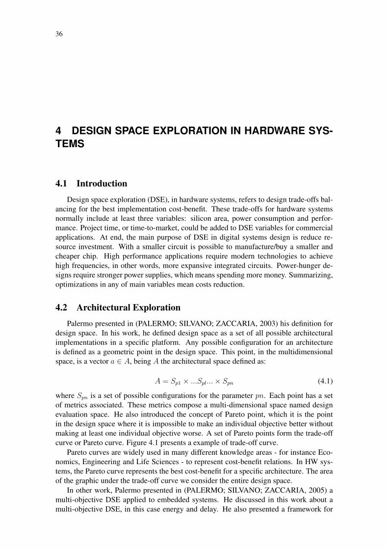
where Spn is a set of possible configurations for the parameter pn. Each point has a setof metrics associated. These metrics compose a multi-dimensional space named designevaluation space. He also introduced the concept of Pareto point, which it is the pointin the design space where it is impossible to make an individual objective better withoutmaking at least one individual objective worse. A set of Pareto points form the trade-offcurve or Pareto curve. Figure 4.1 presents a example of trade-off curve.
Pareto curves are widely used in many different knowledge areas - for instance Eco-nomics, Engineering and Life Sciences - to represent cost-benefit relations. In HW sys-tems, the Pareto curve represents the best cost-benefit for a specific architecture. The areaof the graphic under the trade-off curve we consider the entire design space.
In other work, Palermo presented in (PALERMO; SILVANO; ZACCARIA, 2005) amulti-objective DSE applied to embedded systems. He discussed in this work about amulti-objective DSE, in this case energy and delay. He also presented a framework for

37
Figure 4.1: Pareto Curve.
Source: Wikipedia, the free encyclopedia.
for DSE in order to approximate the Pareto optimality. This framework presents a com-position of three Pareto approximation algorithms, basically derived from Monte Carloanalysis.
In the literature, we can find many works on DSE applied to digital systems. Mostof them present methodologies for high efficient DSE, which include exploration algo-rithms and efficient hardware design partitioning. Sotiropoulou, for example, presentedin (SOTIROPOULOU; NIKOLAIDIS, 2010) a methodology for DSE applied to FPGA-based multiprocessing systems. In her work, she presented an efficient JPEG algorithmpartitioning in processors implemented in an FPGA, allowing data and task-level par-allelism for each processor. She presented four different multiprocessing architectures,each one optimized for a specific design exploration. She also defined a relation calledHW efficiency, presented as follows:
38
HWeff =SpeedUp
Areainc(4.2)
where the SpeedUp represents the performance improvement and Areainc represents thearea increasing for that SpeedUp result.
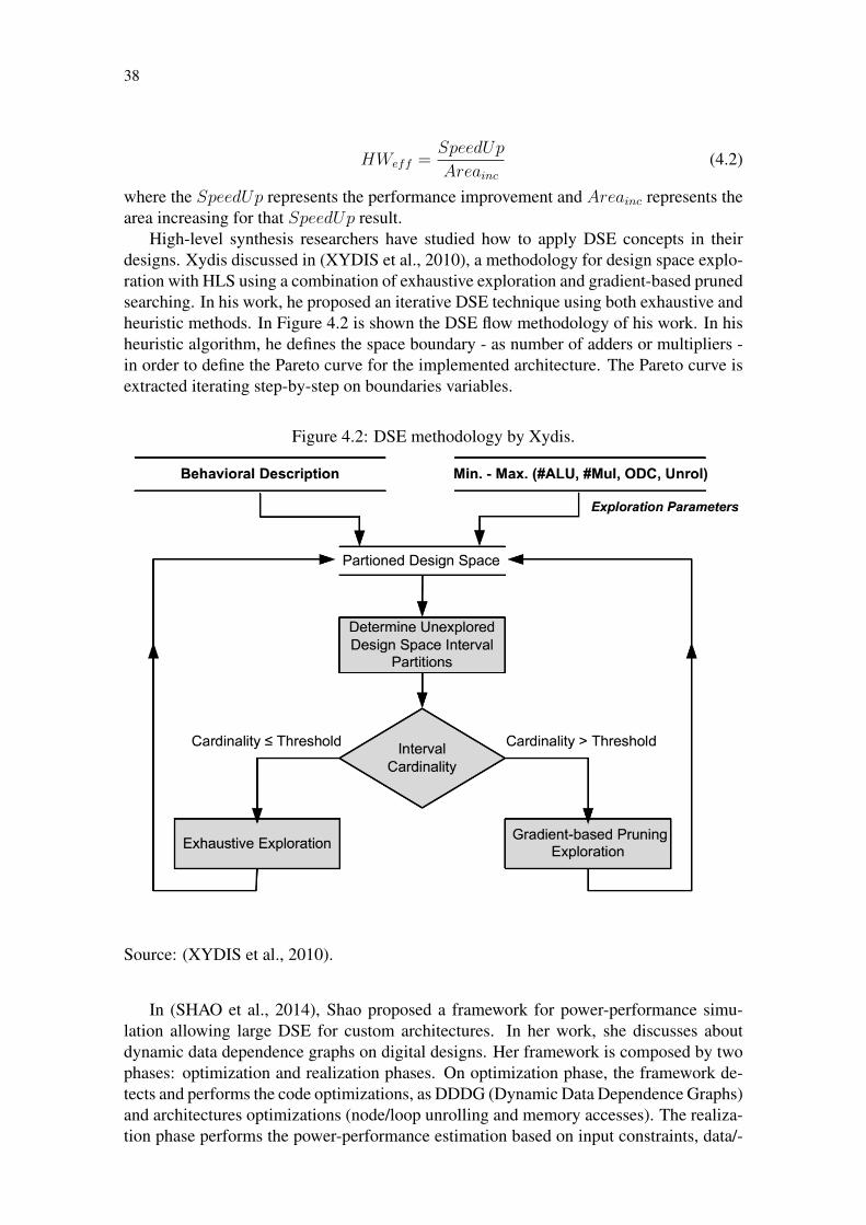
High-level synthesis researchers have studied how to apply DSE concepts in theirdesigns. Xydis discussed in (XYDIS et al., 2010), a methodology for design space explo-ration with HLS using a combination of exhaustive exploration and gradient-based prunedsearching. In his work, he proposed an iterative DSE technique using both exhaustive andheuristic methods. In Figure 4.2 is shown the DSE flow methodology of his work. In hisheuristic algorithm, he defines the space boundary - as number of adders or multipliers -in order to define the Pareto curve for the implemented architecture. The Pareto curve isextracted iterating step-by-step on boundaries variables.
Figure 4.2: DSE methodology by Xydis.
Source: (XYDIS et al., 2010).
In (SHAO et al., 2014), Shao proposed a framework for power-performance simu-lation allowing large DSE for custom architectures. In her work, she discusses aboutdynamic data dependence graphs on digital designs. Her framework is composed by twophases: optimization and realization phases. On optimization phase, the framework de-tects and performs the code optimizations, as DDDG (Dynamic Data Dependence Graphs)and architectures optimizations (node/loop unrolling and memory accesses). The realiza-tion phase performs the power-performance estimation based on input constraints, data/-

39
control dependencies, etc. She also discusses about code tuning and presented a com-parison between tuned/untuned C codes, which is presented in Figure 4.3. Code tuningis a key factor in HLS design flow, allowing hardware parallelism, pipelining and falsedata/control dependencies removal.
Figure 4.3: Tuned and Untuned C code comparison.
Source: (SHAO et al., 2014).
4.3 Conclusions
HLS methods can help considerably the design space exploration. The basics of thisexploration is introduced in this chapter. The importance of optimizing the input high-level description was emphasized, based on previous works presented in the literature.

40
5 METHODOLOGY PROPOSED FOR ARCHITECTURALEXPLORATION
This chapter presents the methodology used for this work. The current work targetsthe high-level architectural exploration, thereby our methodology is mainly focused intwo high-level methods: high-level code tuning and an iterative method for design spaceexploration. The first method was based on similar works (SOTIROPOULOU; NIKO-LAIDIS, 2010; SHAO et al., 2014) present in the literature. The framework we developedis based on Xydis work (XYDIS et al., 2010). Next sections will present these methodsin details.
5.1 High-Level Code Tuning
High-level code abstractions, normally, are not well welcome in HLS tools. How-ever, high abstraction is common in C-based languages and this property makes the HLSdevelopment easier for fast turn-around purpose. To fill this gap, we have to adapt thesource code to get the expected results. These code transformations include: efficientcode partitioning and appropriate HLS directives exploration.
C-based codes are serially executed. As an FPGA designer, we have to translate thisserial code onto an FPGA-targeted parallel code. A transformation we studied in this workwas the efficient code partitioning (PELLERIN; THIBAULT, 2005). A well partitionedcode allows the HLS tool to interpret correctly the source code for proper optimizations.Techniques as loop pipelining, loop unrolling and resource sharing are possible using thismethod. The technique we implemented in this work detects code snippets working as ablock and isolate them in a function. Figure 5.1 shows an example of code transformationon a kernel C-based snippet code. This code transformation allows to drive the synthesisfor at lest for two parameters: area reduction and performance improvement. For areareduction, the synthesis tool implements only one hardware block for the function kernel.Aiming at performance increase, the synthesis process implements the necessary numberof kernel hardware modules for maximum parallelism.
Code partitioning and HLS parameters exploration are closely related. On VivadoTM
HLS, the implementation parameters could be inserted directly on the source code - usingpragmas - or through a constraint script. With the source code functionally divided, theHLS parameters insertion can be more assertive. For performance purpose, the moreuseful parameters are: pipelining, loop unrolling, array partitioning and datapath. Whenthe target is area, common used parameters are inlining functions and resource sharing. Asexample of HLS parameters usage, we present the snippet code below extracted from ourC-based VLIW processor implementation, based on Wong work (WONG; AS; BROWN,

41
Figure 5.1: Code transformation example: Original code, on left. On right, code parti-tioned.
void foo ( ) void k e r n e l ( i n t ∗a , i n t ∗b ) f o r ( i n t i = 1 ; i < 1 0 ; i ++) f o r ( i n t i = 1 ; i < 1 0 ; i ++)
b [ i ] += b [ i −1]∗ a [ i ] ; b [ i ] += b [ i −1]∗ a [ i ] ;f o r ( i n t i = 1 ; i < 1 0 ; i ++)
d [ i ] += d [ i −1]∗ c [ i ] ; void foo ( ) f o r ( i n t i = 1 ; i < 1 0 ; i ++) k e r n e l ( a , b ) ;
f [ i ] += f [ i −1]∗ e [ i ] ; k e r n e l ( c , d ) ; k e r n e l ( e , f ) ;
Source: the author.
2008):
Figure 5.2: Code Snippet Example of a VLIW Implementaion.
void e x e c u t e ( . . . ). . .
/∗ Perform ALU o p e r a t i o n s ∗ /L2 : f o r ( i = 0 ; i < ALU_NUM; i ++)
a l u ( op_code [ i ] , A_op [ i ] , B_op [ i ] , &a l u _ r e s u l t [ i ] ) ;
. . .
Source: the author.
For area optimization, we used the snippet script below:
s e t _ d i r e c t i v e _ a l l o c a t i o n − l i m i t 1 −type f u n c t i o n " e x e c u t e / L2 " a l u
This directive forces the HLS tool to implement just one alu function. This func-tion is translated to just one RTL block, which is shared for each loop iteration. Thisimplementation reduces area, but increases the execution time by a factor of the integerALU_NUM.
For speed optimization, we used the snippet script below:
s e t _ d i r e c t i v e _ a l l o c a t i o n − l i m i t ALU_NUM −type f u n c t i o n " e x e c u t e / L2 " a l us e t _ d i r e c t i v e _ u n r o l l " e x e c u t e / L2 "
Using the script above, the alu is implemented ALU_NUM times. This code hasno data dependency, thus, the function alu is translated to ALU_NUM hardware blocks,which are executed in parallel. The area overhead increases by a factor ALU_NUM.

42
5.2 Iterative Design Space Exploration Method with High-level Syn-thesis
The methods discussed in the Section 5.1 are tedious to exploit all possible combi-nations and have a lower efficiency if applied manually. To support these methods, weimplemented an iterative DSE framework. This method allows a quick response in termsof trade-off analysis.
In this section we present the DSE methodology adopted in our DSE framework. Ourframework explores efficiently the design space aiming at achieving better area resultscompared to non-guided HLS flow. This framework is targeted to Xilinx FPGAs andthe framework result is the best directives file for the VivadoTM HLS tool, in a TCL (ToolCommand Language) format. It is important to highlight that our method does not provideany architectural transformation in the source code, it only discovers the proper set ofHLS directives for efficient DSE. Hence, it is a fact that a true design space explorationin general terms requires a more complex, designer-driven exploration.
Our framework is an iterative, recursive and multi-platform method, developed in afree and high-level language, called Lua (LUA, 2014). The Lua executable is availablefor download at http://www.lua.org/download.html.
We used as a basis for this framework implementation the work proposed by Xydis in(XYDIS et al., 2010). The Xydis work was already discussed in the Chapter 4.
Figure 5.3 presents a simplified view of our framework flow for DSE, which uses theVivadoTM commercial tool at its core as an engine to be driven by our strategy for DSE. Inthe next sub-chapters, we will discuss the implementation of our automatic DSE method.
5.2.1 High-level Design Entry
The current version of our DSE framework supports as input languages both ANSI Cand C++. Some code guidelines should be observed for proper functioning of the DSEscript. These guidelines include:
• Loops labelling, for instance: Loop1: for (int i = 0; i <10; i++);
• Sequential and conditional blocks markers, the ’’ character, should be placed on anew line;
• Array declarations should be written just one per line;
• Returning function types cannot be a defined type. The input high-level descriptionsupports only language native type, such as: void, int, short int, etc.
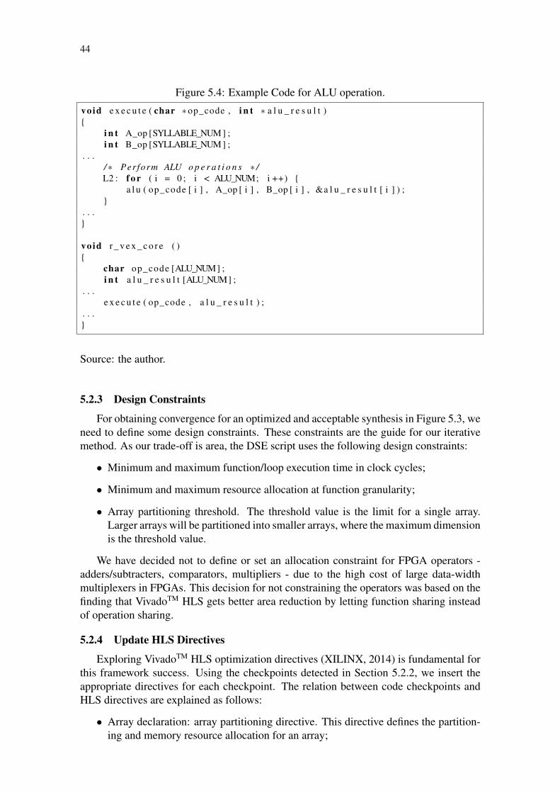
Furthermore, for maximization of optimization results, a well partitioned high-levelcode is extremely necessary. The code writing guidelines are important to steer the HLStool through the steps of synthesis. A snippet C code example is shown in Figure 5.4.
5.2.2 High-Level Parsing
High-level parsing step is responsible for detecting key points in the C/C++ codewhere some optimization directive can be inserted. Our DSE script is capable of detectingfunctions and arrays declarations, loops and multiple function execution. As a start, wehave decided to detect these kind of checkpoints, due to the wide possibilities for areaoptimizations.

43
Figure 5.3: DSE Framework Flow.
Source: the author.
For this step, we had to work with regular expressions and a searching algorithm tofind out the correct points for design optimization. The high-level parsing algorithm hadto be able to determine when multiple blocks are executed inside others. To synthesizearea-efficient hardware with HLS, it is necessary to discover the exact number of possiblefunctions execution.
Observing snippet code shown in Figure 5.4, our framework is able to detect thecheckpoints below:
• Function declarations: r_vex_core and execute;
• Loops execution: L2;
• Array declarations: op_code, A_op, B_op and alu_result;
• Multiple function execution: ALU_NUM*execute.
44
Figure 5.4: Example Code for ALU operation.
void e x e c u t e ( char ∗op_code , i n t ∗ a l u _ r e s u l t )
i n t A_op [SYLLABLE_NUM ] ;i n t B_op [SYLLABLE_NUM ] ;
. . ./∗ Perform ALU o p e r a t i o n s ∗ /L2 : f o r ( i = 0 ; i < ALU_NUM; i ++)
a l u ( op_code [ i ] , A_op [ i ] , B_op [ i ] , &a l u _ r e s u l t [ i ] ) ;
. . .
void r _ v e x _ c o r e ( )
char op_code [ALU_NUM] ;i n t a l u _ r e s u l t [ALU_NUM] ;
. . .e x e c u t e ( op_code , a l u _ r e s u l t ) ;
. . .
Source: the author.
5.2.3 Design Constraints
For obtaining convergence for an optimized and acceptable synthesis in Figure 5.3, weneed to define some design constraints. These constraints are the guide for our iterativemethod. As our trade-off is area, the DSE script uses the following design constraints:
• Minimum and maximum function/loop execution time in clock cycles;
• Minimum and maximum resource allocation at function granularity;
• Array partitioning threshold. The threshold value is the limit for a single array.Larger arrays will be partitioned into smaller arrays, where the maximum dimensionis the threshold value.
We have decided not to define or set an allocation constraint for FPGA operators -adders/subtracters, comparators, multipliers - due to the high cost of large data-widthmultiplexers in FPGAs. This decision for not constraining the operators was based on thefinding that VivadoTM HLS gets better area reduction by letting function sharing insteadof operation sharing.
5.2.4 Update HLS Directives
Exploring VivadoTM HLS optimization directives (XILINX, 2014) is fundamental forthis framework success. Using the checkpoints detected in Section 5.2.2, we insert theappropriate directives for each checkpoint. The relation between code checkpoints andHLS directives are explained as follows:
• Array declaration: array partitioning directive. This directive defines the partition-ing and memory resource allocation for an array;
45
• Function declaration: code inline directive. Inline a code snippet;
• Loop detection: execution time directive. Set a defined latency for execution, re-moving pipelining inferring;
• Multiple function execution: resource allocation directive. Allows HW resourcesharing.
5.2.5 Results Parsing and Analysis
The criterion of acceptance for our DSE framework is better area results. We assumeas area elements the number of FFs and LUTs. The area consumption information isextracted from the parsing of the synthesis report file. Regular expressions were used todetect LUTs, FFs, latency and maximum frequency from report file. Being an iterativemethod, our stop criterion is the convergence of the DSE script, in other words, we stopwhen the maximum area optimization was achieved for the target design (Areaiteration n
>Areaiteration n-1).
5.3 Methodology Summary
This chapter presented the methodology proposed in this work. This first section dis-cuss about high-level code transformation aiming at Quality of Results (QoR) improve-ment. We presented a code partitioning methodology and how to explore the HLS com-pilation directives.
We also presented a automatic DSE method for area reduction purpose. We describeall steps and requirements for the convergence of the proposed framework. This methodis described in a high-level script language and it is compatible with VivadoTM HLS Com-piler. Out method trades-off area and performance aiming at achieving the best QoR forthe given implementation. At this moment we are not concerned in the power impactsof the propose DSE method, however, reducing the area usage also contributes to powersavings.

46
6 HIGH-LEVEL SYNTHESIS EXPERIMENTS
To support this study, this chapter presents the results on HLS design flow. The resultschapter is in two parts: i) HLS tools and design methods comparison and ii) design spaceexploration in HLS environment using the method discussed in the Chapter 5. In the firstsection, we present the comparison between two different HLS tools: an academic toolcalled LegUp and the commercial VivadoTM HLS. In this section, we also compare theresults of the HLS flow with hand-coded design for each test-case. For second section,we present the results of design exploration methods on HLS. At this time we are onlyable to present the DSE methods results for VivadoTM HLS flow.
6.1 High-Level Synthesis Tools and Design Methods Comparison Re-sults
This section presents the HLS compilers comparison results for HLS design. It isalso presented in this section the comparison between high-level description flow againsthand-coded HDL design flow. For results evaluation we used four test cases:
• a MIPS processor;
• an integer square root algorithm;
• a VLIW processor;
• a FIR filter.
Next sub-sections describe the experiments and their results.
6.1.1 MIPS processor
This experiment aims at comparing two different implementations for a MIPS proces-sor. As discussed previously, the MIPS architecture was introduced by Patterson (PAT-TERSON; HENNESSY, 2007) in the 1980’s and this processor is still usual for perfor-mance evaluation purpose. A high-level MIPS processor, proposed by Hara in (HARAet al., 2008), written in C language and a VHDL implementation were compared in termsof area, CT (Compute Time), frequency and code complexity. The MIPS processor usedas benchmark, for both C/C++ and VHDL, is a monocycle machine, with no cache andno external memory. The hand-code VHDL was developed by the author for this project.For this experiment we used the LegUp compiler (CANIS et al., 2011) as HLS tool,

47
QuartusTM II as synthesis tool and the FPGA target was a CycloneTM IV. Both, synthe-sis tool and FPGA device are provided by Altera Inc. The results of this experiment areshown in Table 6.1.
For performance evaluation, we considered CT as the time necessary for a test pro-gram execution. The test program used as benchmark was a bubble-sort algorithm. Theassumed code complexity metric is the sum of the lines of code of all source files used forthis experiment, excluding comment lines. The area metric was measured in terms of LE,which in case of CycloneTM IV FPGA has one four inputs LUT (Look-up Table) and oneFF.
Table 6.1: MIPS Implementation Comparison.Method Area CT Frequency Code Complexity
(LE) (cycles) (MHz) (lines of code)C/C++ 4579 5472 72.22 320
Hand-coded VHDL 9070 611 44.92 1200
The results shown in the Table 6.1 suggest:
1. Area reduction in HLS method: That suggests that the HLS tool has an area orientedmapping algorithm, including resources sharing and re-utilization.
2. Better performance in hand-coded method: even with the higher frequency on HLSmethod, the CT is much shorter in the microprocessor obtained by hand-coded RTLdesign. This could be explained because of HLS tool heuristics for area reduction.
3. Lower complexity using C language: high-level constructions make the code easierand shorter compared to RTL design. RTL descriptions normally require bit-levelaccuracy, while in high-level it is not necessary. Some code guidelines are requiredon hand-coded RTL design, such latch-avoid techniques and careful FSM imple-mentations. These techniques are automatically performed by HLS tool.
6.1.2 32 bit Integer Square Root Algorithm
Four different implementations for a 32 bits Integer Square Root Algorithm were donefor RTL hand-made versus HLS comparison. The algorithm used for this experiment isshown in Figure 6.1. Both RTL and high-level implementations were provided by authorfor this work.
The algorithm shown in Figure 6.1 was directly used as input of HLS tool using Clanguage. Three different VHDL implementation were proposed: a non-optimized de-scription, an area-oriented description and a performance-oriented description.
In this experiment, we used the LegUp C compiler for HLS flow, QuartusTM II andCycloneTM IV as FPGA device. For performance comparison we considered CT as thetime necessary for a 32 bit integer square root calculation, in this case it was the worstcase input interger: 0xFFFFFFFF. The code complexity metric was the same used in theSection 6.1.1. Table 6.2 shows the results obtained for these different implementations.
According Table 6.2 we can conclude:
1. Similarity between VHDL SW (Software) pipeline implementation and HLS method:That suggests the HLS tool has some datapath optimization technique. Pipeline isa very common technique in datapath oriented algorithms.

48
Figure 6.1: Square Root Algorithm Pseudo-code.function SQRT(I)
r ← 1d← 2s← 4while s− I ≤ 0 do
r ← r + 1d← d+ 2s← s+ d+ 1
end whilereturn r
end function
Source: the author.
Table 6.2: Square Root Algorithm Implementation Comparison.Method Area CT Frequency Code Complexity
(LE) (cycles) (MHz) (lines of code)C/C++ 255 46343 123.9 15
Hand-coded VHDL 180 185368 311.14 240Hand-coded VHDL (HW re-utilization) 101 231707 308.93 200
Hand-coded VHDL (SW Pipeline) 227 46353 233.48 230
2. Worst performance in VHDL, excepts with SW pipeline implementation: evenachieving higher frequency, the VHDL techniques are much worse than HLS. Thearea reduction is not good enough to compensate the worst performance.
3. Code complexity: all three VHDL implementations have more than 10 the timesnumber of lines of code compared to high-level implementation.
6.1.3 VLIW Processor
In this experiment, we implemented an academic VLIW processor aiming at com-paring HLS tools. The chosen VLIW processor was the ρ-Vex processor, designed byWong in (WONG; AS; BROWN, 2008). The RTL model is open source available fordownload at https://code.google.com/p/r-vex/. We developed a high-levelimplementation for ρ-Vex processor using C language and this code was used as designentry for both HLS tools. The processor implemented was a four issue VLIW architec-ture, according to the scheme already presented in the Section 2.3. The high-level inputC code is available in the Appendix B.1.
The main purpose of this experiment was the HLS tools comparison. For this, we usedthe LegUp C HLS compiler and the VivadoTM HLS compiler, provided by Xilinx Inc. Forperformance analysis, we considered CT as the worst case instruction compute time, forthis case a 32 bits multiplication. The code complexity metric was the same used in theSection 6.1.1. In this experiment we considered for area consumption analysis not justlogic elements, but also memory blocks and DSP blocks, due to processor complexity.
The LegUp results are shown in the Table 6.3. The synthesis tool used in this experi-ments was QuartusTM II and the target FPGA was a CycloneTM IV. Each RAM block on

49
a CycloneTM IV has storage capacity of 8 kb. The multipliers on this device can operateinputs with 9 bits width.
Table 6.3: ρ-Vex Synthesis Results Using LegUp Compiler.Method Area DSP RAM CT Frequency Code Complexity
(LE) Blocks Blocks (cycles) (MHz) (lines of code)C/C++ 7122 24 29 514 123.9 801
Hand-coded VHDL 1771 2 0 7 311.14 4359
In the Table 6.4 are presented the synthesis results obtained using VivadoTM HLS.As synthesis tool we used VivadoTM and the target FPGA was an SpartanTM 6. Bothsynthesis tool and FPGA device are provided by Xilinx Inc. The area metric used in thisexperiment was LUTs and FFs. SpartanTM 6 has 6 input LUT, and its RAM blocks have16 kb of storage capacity and the embedded multipliers can operate 18 bits inputs.
Table 6.4: ρ-Vex Synthesis Results Using VivadoTM HLS.Method Area Area DSP RAM CT Frequency Code Complexity
(LUT) (FF) Blocks Blocks (cycles) (MHz) (lines of code)C/C++ 6765 12535 5 2 300 333 801
Hand-coded 4944 1765 10 1 7 119.64 4359VHDL
Comparing Table 6.3 and Table 6.4 we can conclude about each HLS tool:
1. LUTs consumption similarity with both tools: resource allocation mechanism issimilar on both LegUp and VivadoTM.
2. Large RAM blocks usage with LegUp: the schedule algorithm could explain largeconsumption. It is necessary memories to store data context for time scheduling.
3. Large DSP blocks consumption with LegUp: hard blocks allocation technique isworse than VivadoTM, although FFs and LUTs allocation mechanism are better.
4. Better performance on VivadoTM: summarizing previous two topics is clear theperformance results. DSP and RAM macros have a fixed latency, around 3 ns,which explain the best performance on VivadoTM.
6.1.4 12th-order FIR Filter
In this experiment, we implemented a 12-tap FIR filter. The main goal of this ex-periment is to compare two different HLS tools: LegUp and VivadoTM HLS. For thisexperiment, we used a C code provided by Xilinx Inc. The source code could be down-loaded at VivadoTM HLS tutorials web page. The pseudo-code for this FIR filter is shownin Figure 6.2.
We also synthesized a 12-tap FIR filter in VHDL. The implementation is described byMeyer-Baese in (MEYER-BAESE, 2001). In his book, Meyer-Baese describes a genericfilter implementation, where parameters as input and output data width, tap number andmultiplier pipeline stage number can be customized. The original code only supportsAltera devices, we modified the VHDL code to support both Xilinx and Altera devices.

50
Figure 6.2: FIR Filter Pseudo-code.function FIR(x, c[12])
acc← 0data← 0shiftreg[12]← 0i← 11for i ≥ 0 do
if i = 0 thenshiftreg[i]← xdata← x
elseshiftreg[i]← shiftreg[i− 1]data← shiftreg[i]
end ifacc← acc+ data ∗ c[i]i← i− 1
end forreturn acc
end function
Source: the author.
It is important emphasizing that RTL optimizations were not performed, because it is notthe purpose of this implementation, it is used only for propose of comparison.
A FIR filter implementation, proposed by Mirzaei in (MIRZAEI; HOSANGADI;KASTNER, 2006), was also used as benchmark comparison. In his work, Mirzaei pro-poses a multiplier-less 12-bits FIR filter implementation, based on add-shift method. Hepresented multiples FIR filter sizes, but we will compare only the 13-tap filter, whichcould be considered a good approximation to our filters. Furthermore, we consideredonly the area results, in terms of LUTs/FFs, because the FPGA device used in this workis legacy, thereby the performance or power results cannot be considered.
In Table 6.5, we present the comparison between two implementations: Meyer-BaeseRTL based and a high-level implementation with LegUp. Both implementations weretargeted to CycloneTM IV FPGA device and were synthesized with QuartusTM II. Com-parison metrics were the same used in the Section 6.1.3, except CT. CT metric, in thisexperiment, was defined as the time necessary to complete one filtering operation for oneinput sample.
Table 6.5: Synthesis Results for FIR Filter Example: Target Altera CycloneTM IV.Method Area DSP RAM CT Frequency Code Complexity
(LE) Blocks Blocks (cycles) (MHz) (lines of code)C/C++ 990 9 13 60 115.15 20VHDL 511 22 0 1* 242.48 150
by Meyer-Baese
* 14 cycles initial pipeline latency.

51
Table 6.6 shows synthesis results for Xilinx FPGAs. The target FPGA was a SpartanTM
6, synthesized with Xilinx ISE, except for Mirzaei work, which was implemented on aVirtexTM II, also provided by Xilinx Inc.
Table 6.6: Synthesis Results for FIR Filter Example: Target Xilinx SpartanTM 6 and XilinxVirtexTM II.
Method Area Area DSP RAM CT Frequency Code(LUT) (FF) Blocks Blocks (cycles) (MHz) Complexity
(lines of code)C/C++ 730 8220 4 0 47 594 20VHDL 378 353 11 0 1* 128 150
by Meyer-BaeseVHDL 334 739 - - - - -
by Mirzaei**
* 14 cycles initial pipeline latency.** Performance and code complexity metrics not considered.
Analysing Table 6.5 and Table 6.6 we can conclude:
1. Lower code complexity using HLS tools: HLS utilization reduces in almost 10times the code complexity in terms of lines of code. Architectural structures, forinstance pipelining, are automatically performed by both used HLS tools.
2. Large area consumption with HLS method: both tools have similar area consump-tion (LEs or LUTs/FFs), which is worse comparing to VHDL implementations.Although, both tools optimized the design for DSP macros re-utilization.
3. Extremely high frequency using VivadoTM HLS: VivadoTM HLS implements deeppipelines, mainly in the multipliers, increasing the frequency. The large FF utiliza-tion in this method has the same cause: FFs are used in the pipeline registers.
6.2 Design Space Exploration Results
This section presents the results for both interactive and automatic design explorationmethods. Section 6.2.1 shows the results for three compilation methods applied to aVLIW processor. Section 6.2.2 presents the experiments for the proposed iterative DSEmethod for two benchmarks: the ρ-Vex processor and a set of FIR filters.
6.2.1 Interactive DSE Results
The design space exploration is easy with VivadoTM HLS. With VivadoTM it is possibleto define area and performance constraints, using a TCL script, aiming at discovering thebest cost-benefit for the target design. For the VLIW processor we defined 3 differentconstraints:
• Functions sharing: resource sharing is made at level of functions and logical blocks.
• Operators sharing: resource sharing is made at level of operators, for instance adder-s/subtracters, comparators, multipliers.

52
• Un-inlined functions: force functions being executed un-inlined, avoiding HW re-utilization/resource sharing. This method allows the tool instantiate multiple HWmodules.
Figure 6.3 illustrates the area results of manual design space exploration with VivadoTM.Figure 6.4 shows the performance obtained through interactive DSE using VivadoTM. Theprocessor implemented and the assumed compute time (CT) for this experiment are thesame presented in 6.1.3. The baseline flow is the non-guided HLS flow, where it is notsetted any design constraint or synthesis directive.
Figure 6.3: DSE Area Results with VivadoTM.
Source: the author.
According graphics presented in Figure 6.3 and Figure 6.4 we can conclude:
1. Smaller area usage results from using the function sharing method: allows HWresource re-utilization. This method is very effective, lower multiplexers overheadcompared to total area.
2. Bad area result at operators sharing: multiplexers are very expensive in FPGAs.This technique requires a large number of multiplexers and register to select/storethe operators, increasing area.
3. Better performance with un-inlined functions: this technique allows unrolling loops.Loop unrolling is a very effective method for HW parallelism.
4. Higher frequency at baseline: this method infers pipeline in most of operations,increasing frequency, although the CT is also higher. This benchmark is a sequentialmachine, thus it is necessary to finish an operation to start a new one. In this case,the higher frequency does not compensate the large compute time.

53
Figure 6.4: DSE Performance Results with VivadoTM.
Source: the author.
6.2.2 Iterative DSE Method Results
This section presents the results for the iterative DSE method with HLS flow proposedin Section 5.2. We have tested our DSE framework using a VirtexTM 7 FPGA. As firstbenchmark we choose a four-issue academic VLIW processor, called ρ-Vex(WONG; AS;BROWN, 2008). The C code describing this processor was developed by the author. Thebenchmark design description in high-level has 800 lines of code.
For this benchmark we defined the following design constraints:
• Array threshold = 12;
• Maximum execution time = 8 cycles;
• Minimum execution time = 1 cycle;
• Maximum number of function instances = 4;
• Minimum number of function instances = 1.
The machine used for framework execution was an AMD AhtlonTM 7550 Dual-coreprocessor @ 2.5 GHz, 32 bits, 3 GB of RAM memory and Windows 7 operational system.The total framework execution time took 140 minutes, running 70 HLS compilations. Theresults of framework execution are shown in Table 6.7. We consider for this analysis -normalized by baseline results - area metrics, in terms of FFs and LUTs, and performance,represented by the compute time (CT) taken to run out the benchmark. We assume CTas the necessary time to execute the worst case of one ρ-Vex instruction (32 bits integermultiplication). For comparison analysis, we assume the baseline as a non-guided HLS

54
flow. This non-guided synthesis uses no design constraints nor sets specific directivesto the HLS tool. For a more realistic analysis, we also ran one synthesis constrainingthe HLS tool to optimize the results for area reduction, applying only a function inlinedirective to all functions. This synthesis flow was called the "first pass", because it usesthe results obtained in the first iteration of our DSE method. The directives file generatedby DSE script is available in the Appendix B.2.
Table 6.7: DSE Framework Results: VLIW processor.
Benchmark Method FF LUT CT Performance
ρ-Vex Baseline 1.0 1.0 1.0 1.0
ρ-Vex First Pass 0.89 1.08 0.98 1.02
ρ-Vex DSE 0.28 0.68 1.38 0.72
Observing the results obtained in Table 6.7, the area reduction is evident. The numberof FFs used by our method is almost 4x lower than a non-guided HLS flow. Our proposedmethod also reduces number of LUTs by 32% compared to the baseline flow. The FFand LUT reductions cause an overhead of 38% in the CT through our methodology. Ourmethod in comparison to the manual-guided first pass flow also proves to be much betterin terms of area reduction, due to similarity between first pass and baseline flow.
Analysing the cost-benefit ratio of our solution, we had to define a QoR metric. Thismetric was derived from speed/area relation proposed in (SOTIROPOULOU; NIKO-LAIDIS, 2010). A global HW efficiency metric was defined as the quotient among nor-malized performance and area results:
HWeff =SpeednormAreanorm
(6.1)
Considering the QoR metric defined by Equation 6.1, our DSE framework respectsthe relation in Equation 6.2. For this relation we used the medium value between LUTsand FFs to define a normalized area metric.
HWeffDSE> HWeffbaseline
(6.2)
The QoR metric indicates HLS flow using our DSE framework is 50% more efficientthan a baseline HLS flow, i.e., the normalized HWeffDSE = 1.5.
The second test-case used with our DSE method was a 12th-order FIR filter. The Ccode was provided by Xilinx Inc. and it has around 20 lines of code. The machine usedfor DSE execution was the same used for first benchmark. Total runtime of our DSE scriptwas 40 minutes, running 20 HLS compilations. Table 6.8 presents the results of our DSEmethod. The metrics used in this experiment are the same as in first benchmark, exceptfor CT. In this case, CT is the time taken for one filtering operation.
Analysing the results in the Table 6.8, we can observe the area reduction using ourmethod. The FFs consumption are reduced more than 3x, while the LUTs utilization andperformance are almost the same, compared to the baseline flow. Our method also provesbeing around 62% more efficient for this test-case compared to the baseline flow. Forthis benchmark, the first pass synthesis had the same results of the baseline, i.e., only thefunction inline directive was not effective for this example.

55
Table 6.8: DSE Framework Results: FIR Filter.Benchmark Method FF LUT CT Performance HWeff
FIR filter Baseline 1.0 1.0 1.0 1.0 1.0
FIR Filter First Pass 1.0 1.0 1.0 1.0 1.0
FIR filter DSE 0.31 1.02 0.92 1.08 1.62
To assure the scalability capability of the proposed method, we compiled a set of FIRfilters with multiple orders, from 4 taps to 40 taps, with steps of 4 taps. For this we usedthe same generated directives script used for the 12-tap FIR filter experiment. In thisexperiment we used the same machine, HLS tool and FPGA device of previous automaticDSE experiments. The results of this experiment are shown in Table 6.9.
Table 6.9: Synthesis Results for Multiple Order FIR Filter Example.Filter Size Area Area DSP RAM CT Frequency HWeff
(LUT) (FF) Blocks Blocks (cycles) (MHz)4-taps 270 205 2 0 10 81.96 2.858-taps 285 174 2 0 18 81.96 2.14
12-taps 343 190 2 0 38 81.96 1.6216-taps 365 190 2 0 50 81.96 1.8720-taps 378 234 2 0 142 136.80 1.3724-taps 399 234 2 0 170 136.80 1.3628-taps 421 234 2 0 198 136.80 1.3432-taps 271 170 2 1 226 136.80 1.5936-taps 277 174 2 1 254 136.80 1.5740-taps 277 174 2 1 282 136.80 1.57
Analysing data from Table 6.9 we drew two relation graphics: area consumption ver-sus filter size, and performance versus filter size. For area analysis we considered theusage of LUTs and FFs. For performance evaluation we considered the compute time andmaximum operation frequency. These relation curves are presented in Figure 6.5.
Considering data from Table 6.9 and the curves of Figure 6.5 we can affirm that ourproposed method has a regular scalability with the circuit increase. Analysing the per-formance curve we can see a linearity characteristic on compute time increasing, whichis expected in our model, since our optimizations address only area trade-off. In thearea curve, one point calls attention, the drastic area reduction with 32-taps filter. It oc-curs because the data samples and internal products are mapped into block RAMs, not inregisters. Another interesting data from Table 6.9 is the same number DSP macros con-sumption by all filter sizes. It is another characteristic of our method, the MAC (Multiplyand Accumulate) operations are forced to not being unrolled in the kernel loop.

56
Figure 6.5: Multiple Size FIR Filters. a) Area Versus Filter Size Curve. b) PerformanceVersus Filter Size Curve.
Source: the author.
57
7 CONCLUSIONS
This work presented a study about recent techniques in FPGA development flow. Wediscussed about well-known methods for FPGA development aiming at improving FPGAefficiency in terms of area, performance and power. We reviewed the state-of-the art ofthe HLS tools and HLS project methodology aiming at fast turn-around purpose. We alsorevisited the evolution of the HDL languages over the last decades.
Our practical experiments were focused in high-level synthesis utilization targeted toFPGA devices. In this work, we evaluate the results of two HLS tools, one of them is anacademic and open source tool, the LegUp. The other tool analysed in our work was acommercial tool, the VivadoTM HLS compiler. Our practical results with using both toolsshow a notable code complexity and development time reduction, although, in the mostcases, the complexity reduction means a performance decreasing or area overhead, whencompared to a hand-coded HDL design.
Some synthesis results call attention due to the similarity between the RTL designand the HLS method, for instance, the square-root implementation using SW pipelinetechnique. This is explained due to the capability of the HLS tool to perform a pipelineimplementation with few stalls, because we do not have data dependency in this algo-rithm. On the other hand, we observe a wide disparity in some other cases, as in theVLIW implementation, comparing the hand-coded HDL design with the HLS compila-tion for both HLS tool providers. The explanation for this is due the large number ofconditional statements avoiding a efficient scheduling and pipelining technique.
To address this area/performance overhead, we had to improve the high level descrip-tions aiming at better synthesis results. Combining efficient code partitioning and theflexibility of synthesis parameters insertion of VivadoTM HLS compiler, we introducedan iterative method for efficient design space exploration with HLS targeting area re-duction. To support method design, we revisited recent methods for DSE in hardwaresystem, where is introduced the Pareto optimally concept, used to evaluate a cost-benefitof a solution.
Our DSE method results for two test-cases, a VLIW processor and a 12th-order FIRFilter, proved to be very effective when compared to a non-guided HLS flow. Our resultsin terms of area are up to 4X better for the VLIW processor and 3X for the FIR Filterbenchmark. Our method is also much better than the baseline flow in terms of QoR. Ouriterative method is 50% and 62% more efficient than baseline, for the VLIW processorand for the digital filter, respectively.
As future work we addressed improving the proposed DSE method, making it nopurely exhaustive, but using an synthesis heuristic to guide the HLS compilation, reduc-ing then the convergence time. It is also desired to extend the iterative DSE method toother design parameters, such as power and performance. Moreover, this method can and

58
should be extended to others HLS tools and FPGA providers, not limited to an specificvendor.
59
REFERENCES
ALTERA. Altera, Inc. http://www.altera.com, [S.l.], 2014.
BELL, C. G.; NEWELL, A. Computer structures: readings and examples. New York,St. Louis, San Francisco: McGraw-Hill, 1971 c, 1971. (McGraw-Hill computer scienceseries).
CANIS, A. et al. LegUp: high-level synthesis for fpga-based processor/accelera-tor systems. In: ACM/SIGDA INTERNATIONAL SYMPOSIUM ON FIELD PRO-GRAMMABLE GATE ARRAYS, 19., New York, NY, USA. Proceedings. . . ACM,2011. p.33–36. (FPGA ’11).
CHEN, D. et al. LOPASS: a low-power architectural synthesis system for fpgas with in-terconnect estimation and optimization. Very Large Scale Integration (VLSI) Systems,IEEE Transactions on, [S.l.], v.18, n.4, p.564–577, April 2010.
CHOW, C. et al. Dynamic voltage scaling for commercial FPGAs. In: FIELD-PROGRAMMABLE TECHNOLOGY, 2005. PROCEEDINGS. 2005 IEEE INTERNA-TIONAL CONFERENCE ON. Anais. . . [S.l.: s.n.], 2005. p.173–180.
COUSSY, P.; MORAWIEC, A. High-Level Synthesis: from algorithm to digital circuit.1st.ed. [S.l.]: Springer Publishing Company, Incorporated, 2008.
DIRECTOR, S. et al. A design methodology and computer aids for digital VLSI systems.Circuits and Systems, IEEE Transactions on, [S.l.], v.28, n.7, p.634–645, Jul 1981.
FRIEDMAN, T.; YANG, S.-C. Methods Used in an Automatic Logic Design Generator(ALERT). Computers, IEEE Transactions on, [S.l.], v.C-18, n.7, p.593–614, July 1969.
GUPTA, S. et al. SPARK: a high-level synthesis framework for applying parallelizingcompiler transformations. In: VLSI DESIGN, 2003. PROCEEDINGS. 16TH INTERNA-TIONAL CONFERENCE ON. Anais. . . [S.l.: s.n.], 2003. p.461–466.
GURUMANI, S. et al. High-level synthesis of multiple dependent CUDA kernels onFPGA. In: DESIGN AUTOMATION CONFERENCE (ASP-DAC), 2013 18TH ASIAAND SOUTH PACIFIC. Anais. . . [S.l.: s.n.], 2013. p.305–312.
HADJIS, S. et al. Impact of FPGA Architecture on Resource Sharing in High-levelSynthesis. In: ACM/SIGDA INTERNATIONAL SYMPOSIUM ON FIELD PRO-GRAMMABLE GATE ARRAYS, New York, NY, USA. Proceedings. . . ACM, 2012.p.111–114. (FPGA ’12).

60
HARA, Y. et al. CHStone: a benchmark program suite for practical c-based high-level synthesis. In: CIRCUITS AND SYSTEMS, 2008. ISCAS 2008. IEEE INTERNA-TIONAL SYMPOSIUM ON. Anais. . . [S.l.: s.n.], 2008. p.1192–1195.
HARTENSTEIN, R. The History of KARL and ABL. [S.l.]: Universität Kaiserslautern,1993. (Fachbereich Informatik: Interner Bericht).
HUDA, S.; MALLICK, M.; ANDERSON, J. Clock gating architectures for FPGA powerreduction. In: FIELD PROGRAMMABLE LOGIC AND APPLICATIONS, 2009. FPL2009. INTERNATIONAL CONFERENCE ON. Anais. . . [S.l.: s.n.], 2009. p.112–118.
LEE, K. et al. A high level design language for programmable logic devices. VLSI De-sign, [S.l.], p.50–62, Jun 1985.
LHAIRECH-LEBRETON, G.; COUSSY, P.; MARTIN, E. Hierarchical and Multiple-Clock Domain High-Level Synthesis for Low-Power Design on FPGA. In: FIELD PRO-GRAMMABLE LOGIC AND APPLICATIONS (FPL), 2010 INTERNATIONAL CON-FERENCE ON. Anais. . . [S.l.: s.n.], 2010. p.464–468.
LUA. Lua: the programming language. http://www.lua.org/, [S.l.], 2014.
MCFARLAND, M. C.; PARKER, A.; CAMPOSANO, R. The high-level synthesis ofdigital systems. Proceedings of the IEEE, [S.l.], v.78, n.2, p.301–318, Feb 1990.
MEYER-BAESE, U. Digital Signal Processing with Field Programmable Gate Ar-rays. Secaucus, NJ, USA: Springer-Verlag New York, Inc., 2001.
MIRZAEI, S.; HOSANGADI, A.; KASTNER, R. FPGA Implementation of High SpeedFIR Filters Using Add and Shift Method. In: COMPUTER DESIGN, 2006. ICCD 2006.INTERNATIONAL CONFERENCE ON. Anais. . . [S.l.: s.n.], 2006. p.308–313.
MOORE, G. Cramming More Components Onto Integrated Circuits. Proceedings of theIEEE, [S.l.], v.86, n.1, p.82–85, Jan 1998.
OLIVER, J. et al. Clock gating and clock enable for FPGA power reduction. In: PRO-GRAMMABLE LOGIC (SPL), 2012 VIII SOUTHERN CONFERENCE ON. Anais. . .[S.l.: s.n.], 2012. p.1–5.
PALERMO, G.; SILVANO, C.; ZACCARIA, V. A Flexible Framework for Fast Multi-objective Design Space Exploration of Embedded Systems. In: INTEGRATED CIR-CUIT AND SYSTEM DESIGN, POWER AND TIMING MODELING, OPTIMIZA-TION AND SIMULATION, 13TH INTERNATIONAL WORKSHOP, PATMOS 2003,TORINO, ITALY, SEPTEMBER 10-12, 2003, PROCEEDINGS. Anais. . . [S.l.: s.n.],2003. p.249–258.
PALERMO, G.; SILVANO, C.; ZACCARIA, V. Multi-objective Design Space Explo-ration of Embedded Systems. J. Embedded Comput., Amsterdam, The Netherlands,The Netherlands, v.1, n.3, p.305–316, Aug. 2005.
PANDEY, B. et al. Clock Gating Aware Low Power Global Reset ALU and Implemen-tation on 28nm FPGA. In: COMPUTATIONAL INTELLIGENCE AND COMMUNI-CATION NETWORKS (CICN), 2013 5TH INTERNATIONAL CONFERENCE ON.Anais. . . [S.l.: s.n.], 2013. p.413–417.

61
PATTERSON, D. A.; HENNESSY, J. L. Computer Organization and Design: the hard-ware/software interface. 3rd.ed. San Francisco, CA, USA: Morgan Kaufmann PublishersInc., 2007.
PELLERIN, D.; THIBAULT, S. Practical FPGA Programming in C. [S.l.]: PrenticeHall Professional Technical Reference, 2005. (Prentice Hall modern semiconductor de-sign series).
RABAEY, J. M.; CHANDRAKASAN, A.; NIKOLIC, B. Digital Integrated Circuits: adesign perspective. 2nd.ed. [S.l.]: Prentice Hall, 2003.
RAJE, S.; BERGAMASCHI, R. Generalized resource sharing. In: COMPUTER-AIDEDDESIGN, 1997. DIGEST OF TECHNICAL PAPERS., 1997 IEEE/ACM INTERNA-TIONAL CONFERENCE ON. Anais. . . [S.l.: s.n.], 1997. p.326–332.
ROSADO-MUñOZ, A. et al. FPGA Implementation of an Adaptive Filter Robust to Im-pulsive Noise: two approaches. Industrial Electronics, IEEE Transactions on, [S.l.],v.58, n.3, p.860–870, March 2011.
SANCHEZ, F. et al. Comparative of HLS and HDL implementations of a grid synchro-nization algorithm. In: INDUSTRIAL ELECTRONICS SOCIETY, IECON 2013 - 39THANNUAL CONFERENCE OF THE IEEE. Anais. . . [S.l.: s.n.], 2013. p.2232–2237.
SCHAFER, B. Allocation of FPGA DSP-macros in multi-process high-level synthesissystems. In: DESIGN AUTOMATION CONFERENCE (ASP-DAC), 2014 19TH ASIAAND SOUTH PACIFIC. Anais. . . [S.l.: s.n.], 2014. p.616–621.
SHAO, Y. et al. Aladdin: a pre-rtl, power-performance accelerator simulator enablinglarge design space exploration of customized architectures. In: COMPUTER ARCHI-TECTURE (ISCA), 2014 ACM/IEEE 41ST INTERNATIONAL SYMPOSIUM ON.Anais. . . [S.l.: s.n.], 2014. p.97–108.
SOTIROPOULOU, C.-L.; NIKOLAIDIS, S. Design space exploration for FPGA-basedmultiprocessing systems. In: ELECTRONICS, CIRCUITS, AND SYSTEMS (ICECS),2010 17TH IEEE INTERNATIONAL CONFERENCE ON. Anais. . . [S.l.: s.n.], 2010.p.1164–1167.
SUN, W.; WIRTHLIN, M.; NEUENDORFFER, S. FPGA Pipeline Synthesis Design Ex-ploration Using Module Selection and Resource Sharing. Computer-Aided Design ofIntegrated Circuits and Systems, IEEE Transactions on, [S.l.], v.26, n.2, p.254–265,Feb 2007.
SYNOPSYS. Synopsys, Inc. http://www.synopsys.com, [S.l.], 2014.
TAN, M. et al. Multithreaded Pipeline Synthesis for Data-Parallel Kernels. In: IEEE/ACMINTERNATIONAL CONFERENCE ON COMPUTER-AIDED DESIGN (ICCAD), 33.Proceedings. . . [S.l.: s.n.], 2014. (ICCAD’14).
WAKABAYASHI, K.; TAKENAKA, T.; INOUE, H. Mapping complex algorithm intoFPGA with High Level Synthesis reconfigurable chips with High Level Synthesis com-pared with CPU, GPGPU. In: DESIGN AUTOMATION CONFERENCE (ASP-DAC),2014 19TH ASIA AND SOUTH PACIFIC. Anais. . . [S.l.: s.n.], 2014. p.282–284.

62
WONG, S.; AS, T. van; BROWN, G. ρ-VEX: a reconfigurable and extensible softcorevliw processor. In: ICECE TECHNOLOGY, 2008. FPT 2008. INTERNATIONAL CON-FERENCE ON. Anais. . . [S.l.: s.n.], 2008. p.369–372.
XILINX. Xilinx, Inc. http://www.xilinx.com, [S.l.], 2014.
XYDIS, S. et al. Efficient High Level Synthesis Exploration Methodology CombiningExhaustive and Gradient-Based Pruned Searching. In: VLSI (ISVLSI), 2010 IEEE COM-PUTER SOCIETY ANNUAL SYMPOSIUM ON. Anais. . . [S.l.: s.n.], 2010. p.104–109.
ZHANG, Y.; ROIVAINEN, J.; MAMMELA, A. Clock-Gating in FPGAs: a novel andcomparative evaluation. In: DIGITAL SYSTEM DESIGN: ARCHITECTURES, METH-ODS AND TOOLS, 2006. DSD 2006. 9TH EUROMICRO CONFERENCE ON. Anais. . .[S.l.: s.n.], 2006. p.‘584–590.
ZIMMERMANN, G. The Mimola Design System a Computer Aided Digital Proces-sor Design Method. In: DESIGN AUTOMATION, 1979. 16TH CONFERENCE ON.Anais. . . [S.l.: s.n.], 1979. p.53–58.

63
APPENDIX A RESUMO DA DISSERTAÇÃO "ARCHITEC-TURAL EXPLORATION OF DIGITAL SYSTEMS DESIGNFOR FPGAS USING C/C++/SYSTEMC SPECIFICATION LAN-GUAGES"
A.1 Introdução
Dispositivos FPGA são largamente utilizados para rápida implementação de funçõesdigitais em hardware e para emulação de circuitos ASIC (Application-Specific IntegratedCircuit). Entretanto, mesmo os FPGAs do estado-da-arte possuem sérias limitações emtermos de desempenho, utilização de área e consumo de potência. Com o aumento dacomplexidade dos sistemas digitais, técnicas de otimização são necessárias para tornar osprojetos com esses devices competitivos.
Este trabalho discute técnicas conhecidas disponíveis na literatura visando otimizaçãode projeto em FPGAs. Estes métodos incluem técnicas de redução de potência, comoclock gating e voltage/frequency scaling. Em termos de área, é discutida a importânciado compartilhamento de recursos de hardware. Para aumento do desempenho, técnicascomo pipelining, paralelismo e redução de fan-out são revisadas.
O principal objetivo desta dissertação de mestrado é discutir e explorar técnicas deotimização em alto nível aplicadas a sistemas com FPGAs. O projeto RTL (Register-Transfer Level) é um gargalo nos cronogramas de projetos de sistemas digitais. A uti-lização e métodos HLS (High-Level Synthesis) são discutidos visando aumento de produ-tividade em projetos baseados em FPGA. Ferramenta HLS acadêmicas e comerciais sãoapresentadas, bem como técnicas avançadas de projeto utilizando linguagens de especifi-cação, por exemplo C/C++ ou SystemC.
Muitos algoritmos possuem seus padrões em código aberto e estão disponíveis emlinguagens de alto nível, como C. No clássico fluxo de projeto para FPGA, os projetistasde hardware necessitam traduzir esses algoritmos para FPGAs, desempenhando todos asetapas de otimização utilizando linguagens RTL. O desenvolvimento e a verificação RTLé uma tarefa complexa e cara quando comparada a implementações em software. Níveisde abstração mais altos permitem que projetistas de software desenvolvam sistemas paraFPGA utilizando compiladores HLS. Fornecedores de ferramentas HLS afirmam que emcertos casos, a produtividade pode aumentar em até 50% utilizando HLS comparada aoprojeto RTL codificado a mão. A adição de diretivas/pragmas nos compiladores HLS per-mitem que o projetista guie a implementação do algoritmo visando um trade-off especí-fico, por exemplo, desempenho ou redução de área. O processo de verificação utilizandofluxo RTL é bastante complexo devido à dificuldade das linguagens HDL (Hardware De-scription Languages) em descrever comportamento dos circuitos no mundo real, enquanto

64
utilizando linguagens de mais alta abstração é possível emular as condições de operação.Além disso, uma simualação RTL pode levar muitas horas, e até dias, dependendo dacomplexidade do circuito, o que normalmente requer poderosos servidores de simulação.
Neste contexto, este trabalho apresenta um metodologia para projeto digital utilizandolinguagens de alto nível através do fluxo HLS. São exploradas técnicas de particionamentode código e inserção de pragmas visando aumento no Quality of Results (QoR). Neste tra-balho, foi desenolvido um método para exploração de espaço de projeto com HLS visandoredução de área. Este método provou ser muito efetivo quando comparado ao fluxo deprojeto HLS não guiado, sendo até 50% mais eficiente em termos de área utilizando umprocessador VLIW (Very Long Instruction Word) acadêmico como benchmark.
A.1.1 Motivação
O FPGA é um chip pré definido, que possui um grande número de macro célu-las interconectadas uma com as outras através de linhas de roteamento e chaves. Cadamacro célula tem em seu interior um multiplexador configurável que é capaz de imple-mentar todas as equações lógicas das combinações de suas entradas e um elemento dearmazenamento de dados (flip-flop). Dispositivos FPGA modernos incluem blocks dememória RAM (Random Access Memory), blocos de DSP (Digital Signal Processing),PLLs (Phase-locked loop), gigabit transceivers e até processadores.
De acordo com dados de fabricantes de FPGAs, normalmente mais de 70% da áreade silício em um FPGA é destinada a interconxões, o que faz esses dispositivos muitoineficientes em termos de consumo de área. Como uma pastilha pré definida de silício,o consumo de potência é uma problema, porque o componente de potência estática estásempre presente em todo chip, mesmo se as células lógicas e os flip-flops não são usa-dos.Em termos de potência dinâmica, os grandes fabricantes tem feito um grande esforçoem fazer os FPGAs mais eficientes. Componentes hard, como blocos de SRAMs e DSPs -também consomem potência, mas a tésnicas de otimização desses componentes não serãodiscutidas neste trabalho
O desempenho em FPGAs é pior do que em dispositivos ASIC. Enquanto ASICs sãoprojetados visando uma aplicação específica, FPGAs são genéricos e isto impacta direta-mente no desempenho. Muitos níveis lógicos entre elementos de armazenamento, grandesfan-outs, a árvore de relógio, o atraso das linhas de roteamento e o posicionamento fixodos elementos lógicos contribuem para redução da máxima frequência de operação.
O desenvolvimento de hardware tem um alto custo e toma grande porção do tempo deprojeto. O tradicional desenvolvimento para FPGAs é baseado em arquitetura sistêmica,descrição RTL, simulação funcional, e por fim, a síntese lógica e place and route. Nestemétodo, a tarefa mais difícil é a descrição RTL, normalmente um trabalho lento e meticu-loso. Técnicas avançadas em HLS automatizam esta etapa, gerando um código RTL sin-tetizável a partir de uma linguagem de alto nível. Esforços recentes tornaram o projeto desistemas em alto nível competitivos para sistemas baseados em FPGAs. Arquiteturas reg-ulares, como algoritmos DSPs, frequentemente estão presentes na literatura para avaliarimplementações em alto nível. Escalonamento de algoritmos, pipelining de laços/funçõese loop unrolling são técnicas comuns utilizadas pelos fabricantes de ferramentas HLSvisando melhoria nos resultados de síntese.
A.1.2 Contribuições
A principal contribuição desta dissertação de mestrado é propor técnicas de explo-ração em alto nível para sistemas digitais que tem como alvo dispositivos FPGAs. As

65
contribuições deste trabalho estão listadas abaixo:
• Exploração Arquitetural em Alto Nível: para atingir bons resultados de sín-tese com descrições de alto nível, melhorias no código se fazem necessárias. Ametodologia adotada neste trabalho discute algumas destas técnicas utilizadas emambientes HLS. Neste trabalho é proposto uma técnica de particionamento de códigocombinada com inserção de diretivas/pragmas apropriadas de compilação visandomelhoria dos resultados de síntese. Estes métodos foram testados com duas fera-mentas HLS: o LegUp compiler e o VivadoTMHLS compiler.
• Exploração de Espaço de Projeto com Síntese de Alto Nível: visando melhorQoR em ambientes HLS, foi proposto um método iterativo para DSE (Design SpaceExploration) em sistemas de hardware. Este método é multi plataforma escrito emlinguagem e é compatível com o VivadoTMHLS compiler. Este método é basi-camente composto por: análise do código em alto nível, inserção automática dediretivas de compilação e avaliação dos resultados.
A.1.3 Organização da Dissertação
Esta dissertação de mestrado está organizada da seguinte forma: as técnicas de otimiza-ção de hardware são revisadas no Capítulo 2, onde são discutidas metodologias conheci-das para otimização de projetos em termos de área, potência e desempenho para FPGAs.Ferramentas e métodos HLS são revistos no Capítulo 3, sendo apresentado a eveoluçãodas linguagens HLS, as ferramentas HLS do estado-da-arte e os métodos de otimizaçãoem HLS presentes na literatura. Eploração de espaço de projeto em sistemas de hard-ware é apresentado no Capítulo 4, onde são introduzidos importantes conceitos para umeficiente DSE aplicado ao projeto de hardware. No Capitulo 5 é apresentada a metodolo-gia proposta neste trabalho, que inclui melhorias propostas no código em alto nível e ummétodo iterativo para DSE em HLS. O Capítulo 6 apresenta os resultados experimentais,para avaliação das ferramentas HLS e a metodologia de DSE em um amibiente HLS.Finalmente, as conclusões são apresentadas no Capítulo 7.
A.2 Resumo das Contribuições da Dissertação: Exploração Arquite-tural no Projeto de Sistemas Digitais para FPGAs UtilizandoLinguagens de Especificação C/C++/SystemC
Códigos com altos níveis de abstração, normalmente, não são bem aceitos por fer-ramentas HLS. Entretanto, níveis de abstração mais altos são comuns em linguagensderivadas do C e essas propriedades facilitam o desenvolvimento HLS visando aumentona produtividade. Para preencher esta lacuna, é necessário adaptar o código fonte paraobter os resultados esperados. Essas transformações no código incluem: eficiente parti-cionamento de código e exploração adequada das diretivas HLS.
Códigos baseados na liguagem C são serialmente exeutados. O projetista de FPGAdeve traduzir este código serial em um código paralelo para execução em FPGA. Umatransformação estudada neste trabalho foi o particionamento de código (PELLERIN;THIBAULT, 2005). Um código bem particionado permite que a ferramenta HLS inter-prete corretamente o código fonte visando otimizações apropriadas. Técnicas como looppipelining, loop unrolling e compartilhamento de recursos de hardware são possíveis uti-lizando esse método. A técnica implementada neste trabalho detecta trechos de códigoque executam como um bloco e os isola em uma função.

66
Particionamento de código e exploração de parâmetros HLS estão intimamente rela-cionados. No VivadoTM HLS, os parâmetros de compilação podem ser introduzidos di-ratamente no código, através de pragmas, ou através de um script TCL (Tool CommandLanguage). Com um código funcionalmente dividido, a inserção das diretivas HLS sãomais assertivas. Para aumento de performance, os parâmetros mais úteis são: pipelining,loop unrolling, array partitioning e datapath. Quando o objetivo é redução de área, asdiretivas mais comuns são inlining functions e resource sharing.
É difícil e tedioso explorar todas as combinações dos métodos discutidos nos pará-grafos anteriores, e seria ineficiente explorá-los manualmente. Para suportar esses méto-dos, foi implementado um framework iterativo para DSE em ambientes HLS. Este métodopermite uma rápida resposta em termos de análise de trade-off.
Neste contexto é apresentado a metodologia adotada neste método de DSE. O métodoproposto explora eficientemente o espaço de projeto visando atingir melhores resultadosde área comparado ao fluxo HLS não guiado. Este framework tem como alvo FPGAsXilinx e o seu resultado é um arquivo de diretivas TCL visando o menor consumo possívelde área. é importante salientar que este método não provê nenhuma alteração arquiteturalno código fonte, somente descobre quais são as melhores diretivas de otimização para ocódigo em questão.
O framework é um método iterativo, recursivo e multi plataforma desenvolvido emlinguagem Lua. Foi utilizado como base para este método parte do framework propostopor Xydis em (XYDIS et al., 2010). A Figura 5.3 apresenta uma visão simplificada doframework DSE proposto, o qual utiliza o VivadoTM HLS como compilador HLS.
A versão atual do método de DSE suporta C/C++. O código de entrada para o scriptDSE precisa seguir algumas diretrizes para facilitar a convergência do script de DSE.Entre essas diretrizes estão: adicionar labels nos laços, posicionar o caracter de aberturade bloco ’’ sempre em uma nova linha, declarar a variávies uma por linha e utilizarsomente tipos nativos das linguagens C/C++. Além disso, é fundamental que o códigofonte esteja particionado funcionalmente para maximização dos resultados.
A etapa de análise do código de entrada é responsável por identificar pontos chaveno código onde é possível inserir alguma diretiva de otimização. O script é capaz deidentificar declaração de funções e vetores, laços e execuções multiplas de uma mesmafunção. Nesta etapa, foi necessário utilizar-se de expressões regulares e algoritmos debusca para descobrir os pontos exatos para otimização.
Visando convergência do método porposto, foi necessário definir uma lista de re-strições para delimitar o espaço de projeto. Essas restrições servem como guia para oscript de DSE proposto. Entre essas restrições destacam-se: mínimo/máximo tempo deexecução de laços e funções (em ciclos), número mínimo/máximo de recursos para alo-cação em granularidade de função e threshold para particionamento de vetores.
Utilizando os pontos chave de otimização descobertos pelas etapas anteriores, é entãoautilizado o arquivo TCL de restrições e então invoca-se o Xilinx VivadoTM HLS com-piler. Depois da excução da compilação, os resultados são analisados e o script definese continua a iterar sobre o espaço de projeto ou não. O critério de aceitação é menorconsumo de área em relação a iteração anterior.
A.3 Conclusões
Este trabalho apresentou um estudo sobre recentes técnicas no fluxo de desenvolvi-mento de projetos utilizando FPGAs. Foram discutidas métodos conhecidos para desen-

67
vimento com FPGAs visando melhorar a eficiência na síntese em termos de área, desem-penho e pontência. Foram revisadas ferramentas HLS do estado-da-arte e a metodologiade projeto HLS visando aumento de produtividade no projeto de sistemas digitais. Estetrabalho também revisitou a evolução das liguagens HLS nas últimas décadas.
O experimentos deste trabalho focaram na utilização de ferramentas de siíntese de altonível tendo como alvo dispositivos FPGA. Este trabalho avaliou os resultados de duas fer-ramentas HLS, uma delas é uma ferramenta acadêmica e código aberto, o LegUp. A outraferramenta utilizada foi uma ferramenta comercial, o VivadoTM HLS compiler. Os resul-tados práticos utilizando ambas ferramentas mostram a notória redução na complexidadedos códigos e tempo de desenvolvimento, embora, na maioria dos casos, esta redução decomplexidade representou piores resultados em desempenho e área, quando comparadosa projetos codificados a mão utlizando linguagens HDL.
Alguns resultados chamam atenção devido a similaridade entre o projeto RTL e osmétodos HLS, como, por exemplo, a implementação do algoritmo da raiz quadrada uti-lizando a técnica de SW (software) pipelining. Isto é explicado devido à capacidade daferramenta em implementar um pipeline com poucos stalls, porque não há dependência dedados neste algoritmo. Por outro lado, foi observado uma grande disparidade em outroscasos, como na implementação do processador VLIW, comparando com o projeto HDLcodificado a mão e a compilação HLS com ambas as ferramentas analisadas. A expli-cação para isto é o grande número de comandos sequenciais, impossibilitando o eficienteescalonamento de tarefas e implementação de pipeline pelos compiladores HLS.
Para lidar com esses resultados insatisfatórios de área/desempenho, foi necessáriomelhorar as descrições em alto nível visando melhores resultados de síntese. Combi-nando eficiente particionamento de código e a flexibilidade na inserção de diretivas decompilação do VivadoTM HLS compiler, foi introduzido um método iterativo para efi-ciente exploração de espaço de projeto em HLS visando redução de área. Para suportar ométodo proposto, foram revisado recentes métodos para DSE em sistemas de hardware,onde é introduzido o conceito de otimalidade de Pareto, utilizado para avaliar o custo-benefício de uma solução.
Os resultados do método DSE iterativo para dois exemplos, um processador VLIW eum filtro FIR (Finite Impulse Response), provaram ser bastante efetivos quando compara-dos do fluxo HLS não guiado. Os resultados em termos de área foram até 4X melhorespara o processador VLIW e 3X melhores para o exemplo do filtro FIR. O método propostotambém é muito melhor que o fluxo não guiado em termos de QoR, sendo 50% e 62%mais eficiente que o fluxo não guiado, para o processador VLIW e para o filtro digital,respectivamente.
Como trabalho futuro, deseja-se melhorar este método DSE, fazendo com que nãoseja mais puramente exaustivo, utilizando alguma heurística para guiar a compilação,reduzindo então o tempo de convergência. Pretende-se também estender o método DSEdesenvolvido neste trabalho para otimizações envolvendo outros parâmetros de projeto,como potência e desempenho. Além disso, este método DSE pode e deve ser estendidoa outros fabricantes de ferramentas HLS e fornecedores de FPGAs, não limitado a umfabricante específico.

68
APPENDIX B VLIW PROCESSOR SOURCE CODES
B.1 C-code Design Entry
B.1.1 Constants Definitions (r_vex.h)
/∗ ∗∗∗∗∗∗∗∗∗∗∗∗∗∗∗∗∗∗∗∗∗∗∗∗∗∗∗∗∗∗∗∗∗∗∗∗∗∗∗∗∗∗∗∗∗∗∗∗∗∗∗∗∗∗∗∗∗∗∗∗∗∗∗∗∗∗ ∗ //∗ Name : r−Vex p r o c e s s o r c o n s t a n t d e f i n i t i o n s ∗ //∗ Purpose : C o n t r o l and DataPath o f Academic VLIW p r o c e s o r ∗ //∗ Author : J e f e r s o n S a n t i a g o da S i l v a ∗ //∗ Notes : Based on r−Vex s u i t e ( h t t p s : / / code . g oo g l e . com / p / r−vex / ) ∗ //∗ ∗∗∗∗∗∗∗∗∗∗∗∗∗∗∗∗∗∗∗∗∗∗∗∗∗∗∗∗∗∗∗∗∗∗∗∗∗∗∗∗∗∗∗∗∗∗∗∗∗∗∗∗∗∗∗∗∗∗∗∗∗∗∗∗∗∗ ∗ /# i f n d e f RVEX_H# d e f i n e RVEX_H
# i n c l u d e < s t d l i b . h># i n c l u d e < s t d i o . h># i n c l u d e <math . h>
/∗ Misc ∗ /# d e f i n e DEBUG_LEVEL 0
/∗ Gener i c d e f i n i t i o n s ∗ /# d e f i n e DATA_MEM_SIZE 64# d e f i n e SYLLABLE_NUM 4# d e f i n e ALU_NUM 4# d e f i n e MUL_NUM 2# d e f i n e INI_MUL_SLOT 1# d e f i n e CTRL_SLOT 0# d e f i n e MEM_SLOT 3# d e f i n e REGISTER_GR_NUM 64# d e f i n e REGISTER_BR_NUM 8
/∗ Fixed r e g i s t e r s ∗ /# d e f i n e LINK_REGISTER REGISTER_GR_NUM − 1# d e f i n e STACK_POINTER 1
/∗ Opcode d e f i n i t i o n s ∗ /# d e f i n e OP_CODE(X) (X >> 25)# d e f i n e IMM_OP(X) (X >> 23) & 3
/∗ Operands ∗ /# d e f i n e DEST_GR(X) (X >> 17) & 63# d e f i n e SRC1_GR(X) (X >> 11) & 63# d e f i n e SRC2_GR(X) (X >> 05) & 63# d e f i n e DEST_BR(X) (X >> 02) & 7

69
# d e f i n e SHORT_IMM_DATA(X) (X >> 02) & 511# d e f i n e BRANCH_IMM_DATA(X) (X >> 05) & 4095# d e f i n e LONG_LO_IMM_DATA(X) (X >> 01) & 1023# d e f i n e LONG_HI_IMM_DATA(X) (X >> 03) & 0x1FFFFF
/∗ O p e r a t i o n s ∗ //∗ Op code as I n p u t ∗ /# d e f i n e NOP_TYPE(X) X == 0# d e f i n e STOP_TYPE (X) X == 31# d e f i n e ALU_TYPE(X) (X >> 6) == 1# d e f i n e MUL_TYPE(X) (X >> 4) == 0 && !NOP_TYPE(X)# d e f i n e CTRL_TYPE(X) (X >> 4) == 2# d e f i n e MEM_TYPE(X) (X >> 4) == 1
/∗ D e s t i n y o p e r a t i o n as i n p u t ∗ /# d e f i n e BRANCH_DEST(X) X == 0
/∗ Immedia te s w i t c h ∗ //∗ Immedia te o p e r a t i o n as i n p u t ∗ /# d e f i n e NO_IMM 0# d e f i n e SHORT_IMM 1# d e f i n e BRANCH_IMM 2# d e f i n e LONG_IMM 3
/∗ ALU O p e r a t i o n s opcodes ∗ /# d e f i n e ADD 65 / / Add# d e f i n e AND 67 / / B i t w i s e AND# d e f i n e ANDC 68 / / B i t w i s e complement and AND# d e f i n e MAX 69 / / Maximum s i g n e d# d e f i n e MAXU 70 / / Maximum u n s i g n e d# d e f i n e MIN 71 / / Minimum s i g n e d# d e f i n e MINU 72 / / Minimum u n s i g n e d# d e f i n e OR 73 / / B i t w i s e OR# d e f i n e ORC 74 / / B i t w i s e complement and OR# d e f i n e SH1ADD 75 / / S h i f t l e f t 1 and add# d e f i n e SH2ADD 76 / / S h i f t l e f t 2 and add# d e f i n e SH3ADD 77 / / S h i f t l e f t 3 and add# d e f i n e SH4ADD 78 / / S h i f t l e f t 4 and add# d e f i n e SHL 79 / / S h i f t l e f t# d e f i n e SHR 80 / / S h i f t r i g h t s i g n e d# d e f i n e SHRU 81 / / S h i f t r i g h t u n s i g n e d# d e f i n e SUB 82 / / S u b t r a c t# d e f i n e SXTB 83 / / S ign e x t e n d b y t e# d e f i n e SXTH 84 / / S ign e x t e n d h a l f word# d e f i n e ZXTB 85 / / Zero e x t e n d b y t e# d e f i n e ZXTH 86 / / Zero e x t e n d h a l f word# d e f i n e XOR 87 / / B i t w i s e XOR# d e f i n e MOV 88 / / Copy s1 t o o t h e r l o c a t i o n# d e f i n e CMPEQ 89 / / Compare : e q u a l# d e f i n e CMPGE 90 / / Compare : g r e a t e r e q u a l s i g n e d# d e f i n e CMPGEU 91 / / Compare : g r e a t e r e q u a l u n s i g n e d# d e f i n e CMPGT 92 / / Compare : g r e a t e r s i g n e d# d e f i n e CMPGTU 93 / / Compare : g r e a t e r u n s i g n e d# d e f i n e CMPLE 94 / / Compare : l e s s than e q u a l s i g n e d# d e f i n e CMPLEU 95 / / Compare : l e s s than e q u a l u n s i g n e d# d e f i n e CMPLT 96 / / Compare : l e s s than s i g n e d# d e f i n e CMPLTU 97 / / Compare : l e s s than u n s i g n e d
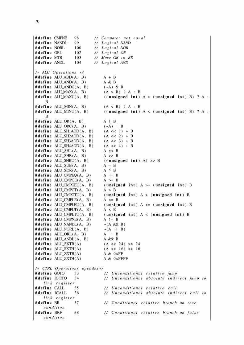
70
# d e f i n e CMPNE 98 / / Compare : n o t e q u a l# d e f i n e NANDL 99 / / L o g i c a l NAND# d e f i n e NORL 100 / / L o g i c a l NOR# d e f i n e ORL 102 / / L o g i c a l OR# d e f i n e MTB 103 / / Move GR t o BR# d e f i n e ANDL 104 / / L o g i c a l AND
/∗ ALU O p e r a t i o n s ∗ /# d e f i n e ALU_ADD(A, B) A + B# d e f i n e ALU_AND(A, B) A & B# d e f i n e ALU_ANDC(A, B) (~A) & B# d e f i n e ALU_MAX(A, B) (A > B) ? A : B# d e f i n e ALU_MAXU(A, B) ( ( unsigned i n t ) A > ( unsigned i n t ) B) ? A :
B# d e f i n e ALU_MIN(A, B) (A < B) ? A : B# d e f i n e ALU_MINU(A, B) ( ( unsigned i n t ) A < ( unsigned i n t ) B) ? A :
B# d e f i n e ALU_OR(A, B) A | B# d e f i n e ALU_ORC(A, B) (~A) | B# d e f i n e ALU_SH1ADD(A, B) (A << 1) + B# d e f i n e ALU_SH2ADD(A, B) (A << 2) + B# d e f i n e ALU_SH3ADD(A, B) (A << 3) + B# d e f i n e ALU_SH4ADD(A, B) (A << 4) + B# d e f i n e ALU_SHL(A, B) A << B# d e f i n e ALU_SHR(A, B) A >> B# d e f i n e ALU_SHRU(A, B) ( ( unsigned i n t ) A) >> B# d e f i n e ALU_SUB(A, B) A − B# d e f i n e ALU_XOR(A, B) A ^ B# d e f i n e ALU_CMPEQ(A, B) A == B# d e f i n e ALU_CMPGE(A, B) A >= B# d e f i n e ALU_CMPGEU(A, B) ( unsigned i n t ) A >= ( unsigned i n t ) B# d e f i n e ALU_CMPGT(A, B) A > B# d e f i n e ALU_CMPGTU(A, B) ( unsigned i n t ) A > ( unsigned i n t ) B# d e f i n e ALU_CMPLE(A, B) A <= B# d e f i n e ALU_CMPLEU(A, B) ( unsigned i n t ) A <= ( unsigned i n t ) B# d e f i n e ALU_CMPLT(A, B) A < B# d e f i n e ALU_CMPLTU(A, B) ( unsigned i n t ) A < ( unsigned i n t ) B# d e f i n e ALU_CMPNE(A, B) A != B# d e f i n e ALU_NANDL(A, B) ~(A && B)# d e f i n e ALU_NORL(A, B) ~(A | | B)# d e f i n e ALU_ORL(A, B) A | | B# d e f i n e ALU_ANDL(A, B) A && B# d e f i n e ALU_SXTB(A) (A << 24) >> 24# d e f i n e ALU_SXTH(A) (A << 16) >> 16# d e f i n e ALU_ZXTB(A) A & 0xFF# d e f i n e ALU_ZXTH(A) A & 0xFFFF
/∗ CTRL O p e r a t i o n s opcodes ∗ /# d e f i n e GOTO 33 / / U n c o n d i t i o n a l r e l a t i v e jump# d e f i n e IGOTO 34 / / U n c o n d i t i o n a l a b s o l u t e i n d i r e c t jump t o
l i n k r e g i s t e r# d e f i n e CALL 35 / / U n c o n d i t i o n a l r e l a t i v e c a l l# d e f i n e ICALL 36 / / U n c o n d i t i o n a l a b s o l u t e i n d i r e c t c a l l t o
l i n k r e g i s t e r# d e f i n e BR 37 / / C o n d i t i o n a l r e l a t i v e branch on t r u e
c o n d i t i o n# d e f i n e BRF 38 / / C o n d i t i o n a l r e l a t i v e branch on f a l s e
c o n d i t i o n

71
# d e f i n e RETURN 39 / / Pop s t a c k frame and go to l i n k r e g i s t e r# d e f i n e RFI 40 / / Re tu rn from i n t e r r u p t# d e f i n e XNOP 41 / / M u l t i c y c l e NOP
/∗ MUL O p e r a t i o n s opcode ∗ /# d e f i n e MPYLL 1 / / M u l t i p l y s i g n e d low 16 x low 16 b i t s# d e f i n e MPYLLU 2 / / M u l t i p l y u n s i g n e d low 16 x low 16 b i t s# d e f i n e MPYLH 3 / / M u l t i p l y s i g n e d low 16 ( s1 ) x h igh 16 (
s2 ) b i t s# d e f i n e MPYLHU 4 / / M u l t i p l y u n s i g n e d low 16 ( s1 ) x h igh 16
( s2 ) b i t s# d e f i n e MPYHH 5 / / M u l t i p l y s i g n e d h igh 16 x h igh 16 b i t s# d e f i n e MPYHHU 6 / / M u l t i p l y u n s i g n e d h igh 16 x h igh 16 b i t s# d e f i n e MPYL 7 / / M u l t i p l y s i g n e d low 16 ( s2 ) x 32 ( s1 )
b i t s# d e f i n e MPYLU 8 / / M u l t i p l y u n s i g n e d low 16 ( s2 ) x 32 ( s1 )
b i t s# d e f i n e MPYH 9 / / M u l t i p l y s i g n e d h igh 16 ( s2 ) x 32 ( s1 )
b i t s# d e f i n e MPYHU 10 / / M u l t i p l y u n s i g n e d h igh 16 ( s2 ) x 32 ( s1 )
b i t s# d e f i n e MPYHS 11 / / M u l t i p l y s i g n e d h igh 16 ( s2 ) x 32 ( s1 )
b i t s , s h i f t l e f t 16
# d e f i n e MUL_MPYLL(A, B) (A & 0xFFFF ) ∗ (B & 0xFFFF )# d e f i n e MUL_MPYLLU(A, B) ( ( unsigned i n t ) (A) & 0xFFFF ) ∗ ( ( unsigned
i n t ) (B) & 0xFFFF )# d e f i n e MUL_MPYLH(A, B) (A >> 16) ∗ (B & 0xFFFF )# d e f i n e MUL_MPYLHU(A, B) ( ( unsigned i n t ) (A) >> 16) ∗ ( ( unsigned i n t )
(B) & 0xFFFF )# d e f i n e MUL_MPYHH(A, B) (A >> 16) ∗ (B >> 16)# d e f i n e MUL_MPYHHU(A, B) ( ( unsigned i n t ) (A) >> 16) ∗ ( ( unsigned i n t )
(B) >> 16)
/∗ MEM O p e r a t i o n s opcodes ∗ /# d e f i n e LDW 17 / / Load word# d e f i n e LDH 18 / / Load h a l f w o r d s i g n e d# d e f i n e LDHU 19 / / Load h a l f w o r d u n s i g n e d# d e f i n e LDB 20 / / Load b y t e s i g n e d# d e f i n e LDBU 21 / / Load b y t e u n s i g n e d# d e f i n e STW 22 / / S t o r e word# d e f i n e STH 23 / / S t o r e h a l f w o r d# d e f i n e STB 24 / / S t o r e b y t e# d e f i n e PFT 25 / / P r e f e t c h
# e n d i f
B.1.2 Instruction Memory (r_vex_imem.h)
/∗ ∗∗∗∗∗∗∗∗∗∗∗∗∗∗∗∗∗∗∗∗∗∗∗∗∗∗∗∗∗∗∗∗∗∗∗∗∗∗∗∗∗∗∗∗∗∗∗∗∗∗∗∗∗∗∗∗∗∗∗∗∗∗∗∗∗∗ ∗ //∗ Name : I n s t r u c t i o n memory f o r r−Vex p r o c e s s o r ∗ //∗ Purpose : C o n t r o l and DataPath o f Academic VLIW p r o c e s o r ∗ //∗ Author : J e f e r s o n S a n t i a g o da S i l v a ∗ //∗ Notes : Based on r−Vex s u i t e ( h t t p s : / / code . g oo g l e . com / p / r−vex / ) ∗ //∗ ∗∗∗∗∗∗∗∗∗∗∗∗∗∗∗∗∗∗∗∗∗∗∗∗∗∗∗∗∗∗∗∗∗∗∗∗∗∗∗∗∗∗∗∗∗∗∗∗∗∗∗∗∗∗∗∗∗∗∗∗∗∗∗∗∗∗ ∗ /
# i f n d e f RVEX_IMEM_H
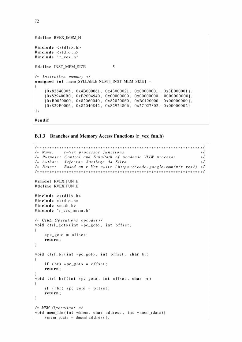
72
# d e f i n e RVEX_IMEM_H
# i n c l u d e < s t d l i b . h># i n c l u d e < s t d i o . h># i n c l u d e " r_vex . h "
# d e f i n e INST_MEM_SIZE 5
/∗ I n s t r c t i o n memory ∗ /unsigned i n t imem [SYLLABLE_NUM] [ INST_MEM_SIZE ] =
0 x82840005 , 0x4B000061 , 0 x43000021 , 0 x00000001 , 0 x3E000001 ,0 x829400B0 , 0xB2004940 , 0 x00000000 , 0 x00000000 , 0000000000 ,0 xB0020000 , 0 x82060040 , 0 x82020060 , 0xB0120000 , 0 x00000000 ,0 x829E0006 , 0 x82040842 , 0 x82924806 , 0x2C027802 , 0 x00000002
;
# e n d i f
B.1.3 Branches and Memory Access Functions (r_vex_fun.h)
/∗ ∗∗∗∗∗∗∗∗∗∗∗∗∗∗∗∗∗∗∗∗∗∗∗∗∗∗∗∗∗∗∗∗∗∗∗∗∗∗∗∗∗∗∗∗∗∗∗∗∗∗∗∗∗∗∗∗∗∗∗∗∗∗∗∗∗∗ ∗ //∗ Name : r−Vex p r o c e s s o r f u n c t i o n s ∗ //∗ Purpose : C o n t r o l and DataPath o f Academic VLIW p r o c e s o r ∗ //∗ Author : J e f e r s o n S a n t i a g o da S i l v a ∗ //∗ Notes : Based on r−Vex s u i t e ( h t t p s : / / code . g oo g l e . com / p / r−vex / ) ∗ //∗ ∗∗∗∗∗∗∗∗∗∗∗∗∗∗∗∗∗∗∗∗∗∗∗∗∗∗∗∗∗∗∗∗∗∗∗∗∗∗∗∗∗∗∗∗∗∗∗∗∗∗∗∗∗∗∗∗∗∗∗∗∗∗∗∗∗∗ ∗ /
# i f n d e f RVEX_FUN_H# d e f i n e RVEX_FUN_H
# i n c l u d e < s t d l i b . h># i n c l u d e < s t d i o . h># i n c l u d e <math . h># i n c l u d e " r_vex_imem . h "
/∗ CTRL O p e r a t i o n s opcodes ∗ /void c t r l _ g o t o ( i n t ∗ pc_goto , i n t o f f s e t )
∗ pc_go to = o f f s e t ;re turn ;
void c t r l _ b r ( i n t ∗ pc_goto , i n t o f f s e t , char br )
i f ( b r ) ∗ pc_go to = o f f s e t ;re turn ;
void c t r l _ b r f ( i n t ∗ pc_goto , i n t o f f s e t , char br )
i f ( ! b r ) ∗ pc_go to = o f f s e t ;re turn ;
/∗ MEM O p e r a t i o n s ∗ /void mem_ldw ( i n t ∗dmem , char a d d r e s s , i n t ∗mem_rdata )
∗mem_rdata = dmem[ a d d r e s s ] ;

73
re turn ;void mem_stw ( i n t ∗dmem , char a d d r e s s , i n t mem_wdata )
dmem[ a d d r e s s ] = mem_wdata ;re turn ;
# e n d i f
B.1.4 Functions Prototype (r_vex_top.h)
/∗ ∗∗∗∗∗∗∗∗∗∗∗∗∗∗∗∗∗∗∗∗∗∗∗∗∗∗∗∗∗∗∗∗∗∗∗∗∗∗∗∗∗∗∗∗∗∗∗∗∗∗∗∗∗∗∗∗∗∗∗∗∗∗∗∗∗∗ ∗ //∗ Name : r−Vex p r o c e s s o r F u n c t i o n s P r o t o t y p e s ∗ //∗ Purpose : C o n t r o l and DataPath o f Academic VLIW p r o c e s o r ∗ //∗ Author : J e f e r s o n S a n t i a g o da S i l v a ∗ //∗ Notes : Based on r−Vex s u i t e ( h t t p s : / / code . g oo g l e . com / p / r−vex / ) ∗ //∗ ∗∗∗∗∗∗∗∗∗∗∗∗∗∗∗∗∗∗∗∗∗∗∗∗∗∗∗∗∗∗∗∗∗∗∗∗∗∗∗∗∗∗∗∗∗∗∗∗∗∗∗∗∗∗∗∗∗∗∗∗∗∗∗∗∗∗ ∗ /
# i f n d e f RVEX_TOP_H# d e f i n e RVEX_TOP_H
# i n c l u d e < s t d l i b . h># i n c l u d e < s t d i o . h># i n c l u d e <math . h># i n c l u d e " r _ v e x _ f u n . h "
/∗ ∗∗∗∗∗∗∗∗∗∗∗∗∗∗∗∗∗∗∗∗∗∗∗∗∗∗∗∗∗∗∗∗∗∗∗∗∗∗∗∗∗∗∗∗∗∗∗∗∗∗∗∗∗∗∗∗∗∗∗∗∗∗∗∗∗∗ ∗ //∗ F u n c t i o n s p r o t o t y p e ∗ //∗ ∗∗∗∗∗∗∗∗∗∗∗∗∗∗∗∗∗∗∗∗∗∗∗∗∗∗∗∗∗∗∗∗∗∗∗∗∗∗∗∗∗∗∗∗∗∗∗∗∗∗∗∗∗∗∗∗∗∗∗∗∗∗∗∗∗∗ ∗ /void advance_pc ( i n t ∗ nex t_pc , i n t pc_go to ) ;void f e t c h ( unsigned i n t imem [SYLLABLE_NUM] [ INST_MEM_SIZE ] , unsigned i n t
∗ s y l l a b l e , i n t pc ) ;void decode ( unsigned i n t ∗ s y l l a b l e , char ∗op_code , char ∗imm_op , char ∗
d e s t _ g r , char ∗ s r c 1 _ g r , char ∗ s r c 2 _ g r , char ∗ d e s t _ b r , i n t ∗shor t_ imm_da ta , i n t ∗ branch_imm_data , i n t ∗ long_imm_data ) ;
void e x e c u t e ( i n t ∗ r eg_g r , i n t dmem[DATA_MEM_SIZE] , char ∗ r eg_b r , char ∗op_code , char ∗imm_op , char ∗ d e s t _ g r , char ∗ s r c 1 _ g r , char ∗ s r c 2 _ g r ,
char ∗ d e s t _ b r , i n t ∗ shor t_ imm_da ta , i n t ∗ branch_imm_data , i n t ∗long_imm_data , i n t ∗ pc_goto , i n t ∗ a l u _ r e s u l t , i n t ∗m u l t _ r e s u l t , i n t∗mem_rdata ) ;
void a l u ( char op_code , i n t A_op , i n t B_op , i n t ∗ a l u _ r e s u l t ) ;void mul t ( char op_code , i n t A_op , i n t B_op , i n t ∗m u l t _ r e s u l t ) ;void c t r l ( i n t ∗ pc_goto , char op_code , i n t o f f s e t , char br ) ;void mem( i n t dmem[DATA_MEM_SIZE] , char op_code , char a d d r e s s , i n t
mem_wdata , i n t ∗mem_rdata ) ;void w r i t e b a c k ( i n t ∗ r eg_g r , char ∗ r eg_b r , char ∗ d e s t _ g r , char ∗ d e s t _ b r ,
char ∗op_code , i n t ∗ a l u _ r e s u l t , i n t ∗m u l t _ r e s u l t , i n t ∗mem_rdata ) ;void r _ v e x _ c o r e ( i n t ∗done , i n t ∗ c y c l e s ) ;
# e n d i f
B.1.5 ρ-Vex Processor Core (r_vex_top.c)
/∗ ∗∗∗∗∗∗∗∗∗∗∗∗∗∗∗∗∗∗∗∗∗∗∗∗∗∗∗∗∗∗∗∗∗∗∗∗∗∗∗∗∗∗∗∗∗∗∗∗∗∗∗∗∗∗∗∗∗∗∗∗∗∗∗∗∗∗ ∗ //∗ Name : r−Vex p r o c e s s o r ∗ //∗ Purpose : C o n t r o l and DataPath o f Academic VLIW p r o c e s o r ∗ /

74
/∗ Author : J e f e r s o n S a n t i a g o da S i l v a ∗ //∗ Notes : Based on r−Vex s u i t e ( h t t p s : / / code . g oo g l e . com / p / r−vex / ) ∗ //∗ ∗∗∗∗∗∗∗∗∗∗∗∗∗∗∗∗∗∗∗∗∗∗∗∗∗∗∗∗∗∗∗∗∗∗∗∗∗∗∗∗∗∗∗∗∗∗∗∗∗∗∗∗∗∗∗∗∗∗∗∗∗∗∗∗∗∗ ∗ /
# i n c l u d e < s t d l i b . h># i n c l u d e < s t d i o . h># i n c l u d e <math . h># i n c l u d e " r _ v e x _ t o p . h "
/∗ ∗∗∗∗∗∗∗∗∗∗∗∗∗∗∗∗∗∗∗∗∗∗∗∗∗∗∗∗∗∗∗∗∗∗∗∗∗∗∗∗∗∗∗∗∗∗∗∗∗∗∗∗∗∗∗∗∗∗∗∗∗∗∗∗∗∗ ∗ //∗ PC c a l c u l a t i o n r o u t i n e ∗ //∗ ∗∗∗∗∗∗∗∗∗∗∗∗∗∗∗∗∗∗∗∗∗∗∗∗∗∗∗∗∗∗∗∗∗∗∗∗∗∗∗∗∗∗∗∗∗∗∗∗∗∗∗∗∗∗∗∗∗∗∗∗∗∗∗∗∗∗ ∗ /void advance_pc ( i n t ∗ nex t_pc , i n t pc_go to )
∗ n e x t _ p c = pc_go to ;re turn ;
/∗ ∗∗∗∗∗∗∗∗∗∗∗∗∗∗∗∗∗∗∗∗∗∗∗∗∗∗∗∗∗∗∗∗∗∗∗∗∗∗∗∗∗∗∗∗∗∗∗∗∗∗∗∗∗∗∗∗∗∗∗∗∗∗∗∗∗∗ ∗ //∗ Fetch i n t r u c t i o n s t a g e r o u t i n e ∗ //∗ ∗∗∗∗∗∗∗∗∗∗∗∗∗∗∗∗∗∗∗∗∗∗∗∗∗∗∗∗∗∗∗∗∗∗∗∗∗∗∗∗∗∗∗∗∗∗∗∗∗∗∗∗∗∗∗∗∗∗∗∗∗∗∗∗∗∗ ∗ /
void f e t c h ( unsigned i n t imem [SYLLABLE_NUM] [ INST_MEM_SIZE ] , unsigned i n t∗ s y l l a b l e , i n t pc )
i n t i ;L1 : f o r ( i = 0 ; i < SYLLABLE_NUM; i ++)
s y l l a b l e [ i ] = imem [ i ] [ pc ] ;re turn ;
/∗ ∗∗∗∗∗∗∗∗∗∗∗∗∗∗∗∗∗∗∗∗∗∗∗∗∗∗∗∗∗∗∗∗∗∗∗∗∗∗∗∗∗∗∗∗∗∗∗∗∗∗∗∗∗∗∗∗∗∗∗∗∗∗∗∗∗∗ ∗ //∗ Decode i n t r u c t i o n s t a g e r o u t i n e ∗ //∗ ∗∗∗∗∗∗∗∗∗∗∗∗∗∗∗∗∗∗∗∗∗∗∗∗∗∗∗∗∗∗∗∗∗∗∗∗∗∗∗∗∗∗∗∗∗∗∗∗∗∗∗∗∗∗∗∗∗∗∗∗∗∗∗∗∗∗ ∗ /void decode ( unsigned i n t ∗ s y l l a b l e , char ∗op_code , char ∗imm_op , char ∗
d e s t _ g r , char ∗ s r c 1 _ g r , char ∗ s r c 2 _ g r , char ∗ d e s t _ b r , i n t ∗shor t_ imm_da ta , i n t ∗ branch_imm_data , i n t ∗ long_imm_data )
i n t i = 0 ;
/∗ Get o p e r a t i o n s and Operands ∗ /L1 : f o r ( i = 0 ; i < SYLLABLE_NUM; i ++)
/∗ Get o p e r a t i o n s ∗ /op_code [ i ] = OP_CODE( s y l l a b l e [ i ] ) ;imm_op [ i ] = IMM_OP( s y l l a b l e [ i ] ) ;
/∗ Get Operands ∗ /d e s t _ g r [ i ] = DEST_GR( s y l l a b l e [ i ] ) ;s r c 1 _ g r [ i ] = SRC1_GR( s y l l a b l e [ i ] ) ;s r c 2 _ g r [ i ] = SRC2_GR( s y l l a b l e [ i ] ) ;d e s t _ b r [ i ] = DEST_BR( s y l l a b l e [ i ] ) ;
s h o r t _ i m m _ d a t a [ i ] = SHORT_IMM_DATA( s y l l a b l e [ i ] ) ;b ranch_imm_data [ i ] = BRANCH_IMM_DATA( s y l l a b l e [ i ] ) ;long_imm_data [ i ] = (LONG_HI_IMM_DATA( s y l l a b l e [ i ] ) << 11) +
LONG_LO_IMM_DATA( s y l l a b l e [ i ] ) ;

75
re turn ;
/∗ ∗∗∗∗∗∗∗∗∗∗∗∗∗∗∗∗∗∗∗∗∗∗∗∗∗∗∗∗∗∗∗∗∗∗∗∗∗∗∗∗∗∗∗∗∗∗∗∗∗∗∗∗∗∗∗∗∗∗∗∗∗∗∗∗∗∗ ∗ //∗ E x e c u t e s t a g e r o u t i n e s ∗ //∗ ∗∗∗∗∗∗∗∗∗∗∗∗∗∗∗∗∗∗∗∗∗∗∗∗∗∗∗∗∗∗∗∗∗∗∗∗∗∗∗∗∗∗∗∗∗∗∗∗∗∗∗∗∗∗∗∗∗∗∗∗∗∗∗∗∗∗ ∗ /void e x e c u t e ( i n t ∗ r eg_g r , i n t ∗dmem , char ∗ r eg_b r , char ∗op_code , char∗imm_op , char ∗ d e s t _ g r , char ∗ s r c 1 _ g r , char ∗ s r c 2 _ g r , char ∗ d e s t _ b r, i n t ∗ shor t_ imm_da ta , i n t ∗ branch_imm_data , i n t ∗ long_imm_data ,i n t ∗ pc_goto , i n t ∗ a l u _ r e s u l t , i n t ∗m u l t _ r e s u l t , i n t ∗mem_rdata )
i n t i = 0 ;i n t A_op [SYLLABLE_NUM ] ;i n t B_op [SYLLABLE_NUM ] ;i n t mem_wdata = r e g _ g r [ d e s t _ g r [MEM_SLOT ] ] ;char br = r e g _ b r [ d e s t _ b r [MEM_SLOT ] ] ;
/ / Get operandsL1 : f o r ( i = 0 ; i < SYLLABLE_NUM; i ++)
A_op [ i ] = r e g _ g r [ s r c 1 _ g r [ i ] ] ;sw i t ch ( imm_op [ i ] )
/ / R e g i s t e r s o p e r a t i o ncase NO_IMM:
B_op [ i ] = r e g _ g r [ s r c 2 _ g r [ i ] ] ;break ;
/ / S h o r t Immedia te o p e r a t i o ncase SHORT_IMM:
B_op [ i ] = s h o r t _ i m m _ d a t a [ i ] ;break ;
/ / Branch Immedia te o p e r a t i o ncase BRANCH_IMM:
B_op [ i ] = branch_imm_data [ i ] ;break ;
/ / Long immed ia t e o p e r a t i o nd e f a u l t :
B_op [ i ] = long_imm_data [ i ] ;break ;
/∗ C o n t r o l o p e r a t i o n s ∗ /c t r l ( pc_goto , op_code [CTRL_SLOT ] , branch_imm_data [CTRL_SLOT ] , ( char
) b r ) ;
/∗ Perform ALU o p e r a t i o n s ∗ /L2 : f o r ( i = 0 ; i < ALU_NUM; i ++)
a l u ( op_code [ i ] , A_op [ i ] , B_op [ i ] , &a l u _ r e s u l t [ i ] ) ;
/∗ Perform MUL o p e r a t i o n s ∗ /L3 : f o r ( i = 0 ; i < MUL_NUM; i ++)
mul t ( op_code [ INI_MUL_SLOT + i ] , A_op [ INI_MUL_SLOT + i ] , B_op [INI_MUL_SLOT + i ] , &m u l t _ r e s u l t [ i ] ) ;
/∗ Perform memory o p e r a t i o n s ∗ /
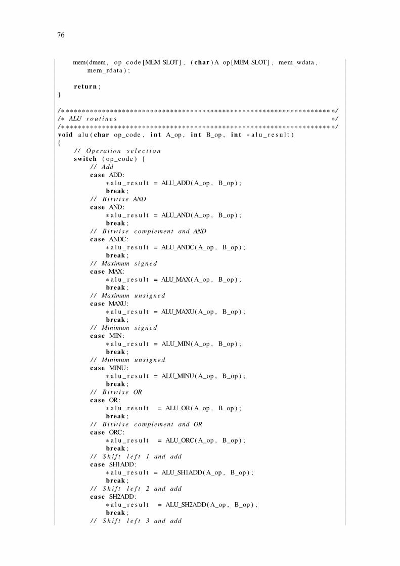
76
mem(dmem , op_code [MEM_SLOT] , ( char ) A_op [MEM_SLOT] , mem_wdata ,mem_rdata ) ;
re turn ;
/∗ ∗∗∗∗∗∗∗∗∗∗∗∗∗∗∗∗∗∗∗∗∗∗∗∗∗∗∗∗∗∗∗∗∗∗∗∗∗∗∗∗∗∗∗∗∗∗∗∗∗∗∗∗∗∗∗∗∗∗∗∗∗∗∗∗∗∗ ∗ //∗ ALU r o u t i n e s ∗ //∗ ∗∗∗∗∗∗∗∗∗∗∗∗∗∗∗∗∗∗∗∗∗∗∗∗∗∗∗∗∗∗∗∗∗∗∗∗∗∗∗∗∗∗∗∗∗∗∗∗∗∗∗∗∗∗∗∗∗∗∗∗∗∗∗∗∗∗ ∗ /void a l u ( char op_code , i n t A_op , i n t B_op , i n t ∗ a l u _ r e s u l t )
/ / O p e r a t i o n s e l e c t i o nsw i t ch ( op_code )
/ / Addcase ADD:
∗ a l u _ r e s u l t = ALU_ADD( A_op , B_op ) ;break ;
/ / B i t w i s e ANDcase AND:
∗ a l u _ r e s u l t = ALU_AND( A_op , B_op ) ;break ;
/ / B i t w i s e complement and ANDcase ANDC:
∗ a l u _ r e s u l t = ALU_ANDC( A_op , B_op ) ;break ;
/ / Maximum s i g n e dcase MAX:
∗ a l u _ r e s u l t = ALU_MAX( A_op , B_op ) ;break ;
/ / Maximum u n s i g n e dcase MAXU:
∗ a l u _ r e s u l t = ALU_MAXU( A_op , B_op ) ;break ;
/ / Minimum s i g n e dcase MIN:
∗ a l u _ r e s u l t = ALU_MIN( A_op , B_op ) ;break ;
/ / Minimum u n s i g n e dcase MINU:
∗ a l u _ r e s u l t = ALU_MINU( A_op , B_op ) ;break ;
/ / B i t w i s e ORcase OR:
∗ a l u _ r e s u l t = ALU_OR( A_op , B_op ) ;break ;
/ / B i t w i s e complement and ORcase ORC:
∗ a l u _ r e s u l t = ALU_ORC( A_op , B_op ) ;break ;
/ / S h i f t l e f t 1 and addcase SH1ADD:
∗ a l u _ r e s u l t = ALU_SH1ADD( A_op , B_op ) ;break ;
/ / S h i f t l e f t 2 and addcase SH2ADD:
∗ a l u _ r e s u l t = ALU_SH2ADD( A_op , B_op ) ;break ;
/ / S h i f t l e f t 3 and add

77
case SH3ADD:∗ a l u _ r e s u l t = ALU_SH3ADD( A_op , B_op ) ;break ;
/ / S h i f t l e f t 4 and addcase SH4ADD:
∗ a l u _ r e s u l t = ALU_SH4ADD( A_op , B_op ) ;break ;
/ / S h i f t l e f tcase SHL :
∗ a l u _ r e s u l t = ALU_SHL( A_op , B_op ) ;break ;
/ / S h i f t r i g h t s i g n e dcase SHR:
∗ a l u _ r e s u l t = ALU_SHR( A_op , B_op ) ;break ;
/ / S h i f t r i g h t u n s i g n e dcase SHRU:
∗ a l u _ r e s u l t = ALU_SHRU( A_op , B_op ) ;break ;
/ / B i t w i s e XORcase XOR:
∗ a l u _ r e s u l t = ALU_XOR( A_op , B_op ) ;break ;
/ / Compare : e q u a lcase CMPEQ:
∗ a l u _ r e s u l t = ALU_CMPEQ( A_op , B_op ) ;break ;
/ / Compare : g r e a t e r e q u a l s i g n e dcase CMPGE:
∗ a l u _ r e s u l t = ALU_CMPGE( A_op , B_op ) ;break ;
/ / Compare : g r e a t e r e q u a l u n s i g n e dcase CMPGEU:
∗ a l u _ r e s u l t = ALU_CMPGEU( A_op , B_op ) ;break ;
/ / Compare : g r e a t e r s i g n e dcase CMPGT:
∗ a l u _ r e s u l t = ALU_CMPGT( A_op , B_op ) ;break ;
/ / Compare : g r e a t e r u n s i g n e dcase CMPGTU:
∗ a l u _ r e s u l t = ALU_CMPGTU( A_op , B_op ) ;break ;
/ / Compare : l e s s than e q u a l s i g n e dcase CMPLE:
∗ a l u _ r e s u l t = ALU_CMPLE( A_op , B_op ) ;break ;
/ / Compare : l e s s than e q u a l u n s i g n e dcase CMPLEU:
∗ a l u _ r e s u l t = ALU_CMPLEU( A_op , B_op ) ;break ;
/ / Compare : l e s s than s i g n e dcase CMPLT:
∗ a l u _ r e s u l t = ALU_CMPLT( A_op , B_op ) ;break ;
/ / Compare : l e s s than u n s i g n e dcase CMPLTU:
∗ a l u _ r e s u l t = ALU_CMPLTU( A_op , B_op ) ;

78
break ;/ / Compare : n o t e q u a lcase CMPNE:
∗ a l u _ r e s u l t = ALU_CMPNE( A_op , B_op ) ;break ;
/ / L o g i c a l NANDcase NANDL:
∗ a l u _ r e s u l t = ALU_NANDL( A_op , B_op ) ;break ;
/ / L o g i c a l NORcase NORL:
∗ a l u _ r e s u l t = ALU_NORL( A_op , B_op ) ;break ;
/ / L o g i c a l ORcase ORL:
∗ a l u _ r e s u l t = ALU_ORL( A_op , B_op ) ;break ;
/ / Move GR t o BRcase MTB:
∗ a l u _ r e s u l t = A_op & 1 ;break ;
/ / S u b t r a c tcase SUB:
∗ a l u _ r e s u l t = ALU_SUB( A_op , B_op ) ;break ;
/ / S ign e x t e n d b y t ecase SXTB :
∗ a l u _ r e s u l t = ALU_SXTB( A_op ) ;break ;
/ / S ign e x t e n d h a l f wordcase SXTH:
∗ a l u _ r e s u l t = ALU_SXTH( A_op ) ;break ;
/ / Zero e x t e n d b y t ecase ZXTB:
∗ a l u _ r e s u l t = ALU_ZXTB( A_op ) ;break ;
/ / Zero e x t e n d h a l f wordcase ZXTH:
∗ a l u _ r e s u l t = ALU_ZXTH( A_op ) ;break ;
/ / Copy s1 t o o t h e r l o c a t i o ncase MOV:
∗ a l u _ r e s u l t = A_op ;break ;
/ / D e f a u l t − Decode Errord e f a u l t :
break ;re turn ;
/∗ ∗∗∗∗∗∗∗∗∗∗∗∗∗∗∗∗∗∗∗∗∗∗∗∗∗∗∗∗∗∗∗∗∗∗∗∗∗∗∗∗∗∗∗∗∗∗∗∗∗∗∗∗∗∗∗∗∗∗∗∗∗∗∗∗∗∗ ∗ //∗ M u l t i p l i c a t i o n r o u t i n e s ∗ //∗ ∗∗∗∗∗∗∗∗∗∗∗∗∗∗∗∗∗∗∗∗∗∗∗∗∗∗∗∗∗∗∗∗∗∗∗∗∗∗∗∗∗∗∗∗∗∗∗∗∗∗∗∗∗∗∗∗∗∗∗∗∗∗∗∗∗∗ ∗ /void mul t ( char op_code , i n t A_op , i n t B_op , i n t ∗m u l t _ r e s u l t )
/ / O p e r a t i o n s e l e c t i o n

79
sw i t ch ( op_code ) / / M u l t i p l y s i g n e d low 16 x low 16 b i t scase MPYLL:
∗m u l t _ r e s u l t = MUL_MPYLL( A_op , B_op ) ;break ;
/ / M u l t i p l y u n s i g n e d low 16 x low 16 b i t scase MPYLLU:
∗m u l t _ r e s u l t = MUL_MPYLLU( A_op , B_op ) ;break ;
/ / M u l t i p l y s i g n e d low 16 ( s1 ) x h igh 16 ( s2 ) b i t scase MPYLH:
∗m u l t _ r e s u l t = MUL_MPYLH( A_op , B_op ) ;break ;
/ / M u l t i p l y u n s i g n e d low 16 ( s1 ) x h igh 16 ( s2 ) b i t scase MPYLHU:
∗m u l t _ r e s u l t = MUL_MPYLHU( A_op , B_op ) ;break ;
/ / M u l t i p l y s i g n e d h igh 16 x h igh 16 b i t scase MPYHH:
∗m u l t _ r e s u l t = MUL_MPYHH( A_op , B_op ) ;break ;
/ / M u l t i p l y u n s i g n e d h igh 16 x h igh 16 b i t scase MPYHHU:
∗m u l t _ r e s u l t = MUL_MPYHHU( A_op , B_op ) ;break ;
/ / D e f a u l t − Decode Errord e f a u l t :
break ;
re turn ;
/∗ ∗∗∗∗∗∗∗∗∗∗∗∗∗∗∗∗∗∗∗∗∗∗∗∗∗∗∗∗∗∗∗∗∗∗∗∗∗∗∗∗∗∗∗∗∗∗∗∗∗∗∗∗∗∗∗∗∗∗∗∗∗∗∗∗∗∗ ∗ //∗ C o n t r o l r o u t i n e s ∗ //∗ ∗∗∗∗∗∗∗∗∗∗∗∗∗∗∗∗∗∗∗∗∗∗∗∗∗∗∗∗∗∗∗∗∗∗∗∗∗∗∗∗∗∗∗∗∗∗∗∗∗∗∗∗∗∗∗∗∗∗∗∗∗∗∗∗∗∗ ∗ /void c t r l ( i n t ∗ pc_goto , char op_code , i n t o f f s e t , char br )
/ / O p e r a t i o n s e l e c t i o nsw i t ch ( op_code )
/ / U n c o n d i t i o n a l r e l a t i v e jumpcase GOTO:
c t r l _ g o t o ( pc_goto , o f f s e t ) ;break ;
/ / C o n d i t i o n a l r e l a t i v e branch on t r u e c o n d i t i o ncase BR:
c t r l _ b r ( pc_goto , o f f s e t , b r ) ;break ;
/ / C o n d i t i o n a l r e l a t i v e branch on f a l s e c o n d i t i o ncase BRF :
c t r l _ b r f ( pc_goto , o f f s e t , b r ) ;break ;
d e f a u l t :break ;
re turn ;

80
/∗ ∗∗∗∗∗∗∗∗∗∗∗∗∗∗∗∗∗∗∗∗∗∗∗∗∗∗∗∗∗∗∗∗∗∗∗∗∗∗∗∗∗∗∗∗∗∗∗∗∗∗∗∗∗∗∗∗∗∗∗∗∗∗∗∗∗∗ ∗ //∗ Memory a c c e s s r o u t i n e s ∗ //∗ ∗∗∗∗∗∗∗∗∗∗∗∗∗∗∗∗∗∗∗∗∗∗∗∗∗∗∗∗∗∗∗∗∗∗∗∗∗∗∗∗∗∗∗∗∗∗∗∗∗∗∗∗∗∗∗∗∗∗∗∗∗∗∗∗∗∗ ∗ /void mem( i n t ∗dmem , char op_code , char a d d r e s s , i n t mem_wdata , i n t ∗
mem_rdata )
/ / O p e r a t i o n s e l e c t i o nsw i t ch ( op_code )
/ / Load wordcase LDW:
mem_ldw (dmem , a d d r e s s , mem_rdata ) ;break ;
/ / S t o r e wordcase STW:
mem_stw (dmem , a d d r e s s , mem_wdata ) ;break ;
/ / D e f a u l t − Decode Errord e f a u l t :
break ;re turn ;
/∗ ∗∗∗∗∗∗∗∗∗∗∗∗∗∗∗∗∗∗∗∗∗∗∗∗∗∗∗∗∗∗∗∗∗∗∗∗∗∗∗∗∗∗∗∗∗∗∗∗∗∗∗∗∗∗∗∗∗∗∗∗∗∗∗∗∗∗ ∗ //∗ W r i t e b a c k r o u t i n e ∗ //∗ ∗∗∗∗∗∗∗∗∗∗∗∗∗∗∗∗∗∗∗∗∗∗∗∗∗∗∗∗∗∗∗∗∗∗∗∗∗∗∗∗∗∗∗∗∗∗∗∗∗∗∗∗∗∗∗∗∗∗∗∗∗∗∗∗∗∗ ∗ /void w r i t e b a c k ( i n t ∗ r eg_g r , char ∗ r eg_b r , char ∗ d e s t _ g r , char ∗ d e s t _ b r ,
char ∗op_code , i n t ∗ a l u _ r e s u l t , i n t ∗m u l t _ r e s u l t , i n t ∗mem_rdata )
i n t i ;L1 : f o r ( i = 0 ; i < SYLLABLE_NUM; i ++)
i f (ALU_TYPE( op_code [ i ] ) ) i f ( d e s t _ g r [ i ] == 0)
r e g _ b r [ d e s t _ b r [ i ] ] = a l u _ r e s u l t [ i ] ;e l s e
r e g _ g r [ d e s t _ g r [ i ] ] = a l u _ r e s u l t [ i ] ;
sw i t ch ( i ) case CTRL_SLOT :
i f (CTRL_TYPE( op_code [CTRL_SLOT ] ) ) break ;
case 1 :i f (MUL_TYPE( op_code [ i ] ) )
r e g _ g r [ d e s t _ g r [ i ] ] = m u l t _ r e s u l t [ 0 ] ;break ;
case 2 :i f (MUL_TYPE( op_code [ i ] ) )
r e g _ g r [ d e s t _ g r [ i ] ] = m u l t _ r e s u l t [ 1 ] ;break ;
case MEM_SLOT:

81
i f (MEM_TYPE( op_code [MEM_SLOT] ) ) r e g _ g r [ d e s t _ g r [ i ] ] = ∗mem_rdata ;
break ;
/∗ ∗∗∗∗∗∗∗∗∗∗∗∗∗∗∗∗∗∗∗∗∗∗∗∗∗∗∗∗∗∗∗∗∗∗∗∗∗∗∗∗∗∗∗∗∗∗∗∗∗∗∗∗∗∗∗∗∗∗∗∗∗∗∗∗∗∗ ∗ //∗ r−Vex core ∗ //∗ ∗∗∗∗∗∗∗∗∗∗∗∗∗∗∗∗∗∗∗∗∗∗∗∗∗∗∗∗∗∗∗∗∗∗∗∗∗∗∗∗∗∗∗∗∗∗∗∗∗∗∗∗∗∗∗∗∗∗∗∗∗∗∗∗∗∗ ∗ /void r _ v e x _ c o r e ( i n t ∗done , i n t ∗ c y c l e s )
i n t i , j = 0 ;
/∗ Flow c o n t r o l ∗ /i n t n e x t _ p c = 0 ;i n t pc_go to = 0 ;
/∗ R e g i s t e r s : g e n e r a l purpose and branch ∗ /i n t r e g _ g r [REGISTER_GR_NUM] = 0 ;char r e g _ b r [REGISTER_BR_NUM] = 0 ;
/∗ Fec th ∗ /unsigned i n t s y l l a b l e [SYLLABLE_NUM ] ;
/∗ Decode v a r i a b l e s ∗ /char op_code [SYLLABLE_NUM ] ;char imm_op [SYLLABLE_NUM ] ;
char d e s t _ g r [SYLLABLE_NUM ] ;char s r c 1 _ g r [SYLLABLE_NUM ] ;char s r c 2 _ g r [SYLLABLE_NUM ] ;char d e s t _ b r [SYLLABLE_NUM ] ;
i n t s h o r t _ i m m _ d a t a [SYLLABLE_NUM ] ;i n t branch_imm_data [SYLLABLE_NUM ] ;i n t long_imm_data [SYLLABLE_NUM ] ;char c ;
i n t dmem[DATA_MEM_SIZE ] ;
i n t a l u _ r e s u l t [ALU_NUM] ;i n t m u l t _ r e s u l t [MUL_NUM] ;i n t mem_rdata ;
/∗ Main Loop ∗ /r _ v e x _ c o r e _ l a b e l 0 : whi le ( 1 )
/∗ PC c a l c u l a t i o n ∗ /advance_pc (& next_pc , pc_go to ) ;
/∗ Fix PC o f f s e t [nPC = nPC + 1] ∗ /pc_go to = n e x t _ p c + 1 ;∗ c y c l e s = ∗ c y c l e s + 1 ;

82
/∗ Fetch i n t r u c t i o n s t a g e r o u t i n e ∗ /f e t c h ( imem , s y l l a b l e , n e x t _ p c ) ;
/∗ Decode i n t r u c t i o n s t a g e r o u t i n e ∗ /decode ( s y l l a b l e , op_code , imm_op , d e s t _ g r , s r c 1 _ g r , s r c 2 _ g r ,
d e s t _ b r , shor t_ imm_da ta , branch_imm_data , long_imm_data ) ;
/∗ D e t e c t s end o f program ∗ /L1 : f o r ( i = 0 ; i < SYLLABLE_NUM; i ++)
i f ( STOP_TYPE ( op_code [ i ] ) ) ∗done = 1 ;re turn ;
/∗ E x e c u t i o n S t a g e ∗ /e x e c u t e ( r eg_gr , dmem , reg_br , op_code , imm_op , d e s t _ g r ,
s r c 1 _ g r , s r c 2 _ g r , d e s t _ b r , shor t_ imm_da ta , branch_imm_data ,long_imm_data , &pc_goto , a l u _ r e s u l t , m u l t _ r e s u l t , &
mem_rdata ) ;
/∗ W r i t e b a c k s t a g e ∗ /w r i t e b a c k ( r eg_g r , r eg_b r , d e s t _ g r , d e s t _ b r , op_code , a l u _ r e s u l t
, m u l t _ r e s u l t , &mem_rdata ) ;
B.1.6 ρ-Vex Processor Testbench (r_vex_tb.h)
/∗ ∗∗∗∗∗∗∗∗∗∗∗∗∗∗∗∗∗∗∗∗∗∗∗∗∗∗∗∗∗∗∗∗∗∗∗∗∗∗∗∗∗∗∗∗∗∗∗∗∗∗∗∗∗∗∗∗∗∗∗∗∗∗∗∗∗∗ ∗ //∗ Name : r−Vex p r o c e s s o r T e s t b e n c h ∗ //∗ Purpose : T e s t b e n c h C o n t r o l and Datapath o f VLIW p r o c e s s o r ∗ //∗ Author : J e f e r s o n S a n t i a g o da S i l v a ∗ //∗ Notes : Based on r−Vex s u i t e ( h t t p s : / / code . g oo g l e . com / p / r−vex / ) ∗ //∗ ∗∗∗∗∗∗∗∗∗∗∗∗∗∗∗∗∗∗∗∗∗∗∗∗∗∗∗∗∗∗∗∗∗∗∗∗∗∗∗∗∗∗∗∗∗∗∗∗∗∗∗∗∗∗∗∗∗∗∗∗∗∗∗∗∗∗ ∗ /
# i n c l u d e < s t d l i b . h># i n c l u d e < s t d i o . h># i n c l u d e <math . h># i n c l u d e " r_vex . h "
i n t main ( )
i n t i = 0 , j = 0 ;i n t program_done = 0 ;i n t c y c l e s = 0 ;
/∗ r−Vex core ∗ /r _ v e x _ c o r e (& program_done , &c y c l e s ) ;
p r i n t f ( "−−−−−−−−−−−−−−−−−−−−−−−−−−−−−−−−\n " ) ;p r i n t f ( " F i n a l e x e c u t i o n \ n " ) ;p r i n t f ( " Program done : %d \ n " , program_done ) ;p r i n t f ( " Number o f i n s t r u c t i o n s : %d \ n " , c y c l e s ) ;p r i n t f ( " R e s u l t : " ) ;

83
i f ( c y c l e s != 94) p r i n t f ( " E r r o r \ n " ) ;
e l s e
p r i n t f ( " Pas se d \ n " ) ;p r i n t f ( "−−−−−−−−−−−−−−−−−−−−−−−−−−−−−−−−\n " ) ;
re turn 0 ;
B.2 Synthesis Directives Generated by DSE Script (directives.tcl)
s e t _ d i r e c t i v e _ i n l i n e " advance_pc "s e t _ d i r e c t i v e _ i n l i n e " decode "s e t _ d i r e c t i v e _ i n l i n e " e x e c u t e "s e t _ d i r e c t i v e _ i n l i n e " c t r l "s e t _ d i r e c t i v e _ i n l i n e "mem"s e t _ d i r e c t i v e _ i n l i n e " w r i t e b a c k "s e t _ d i r e c t i v e _ i n l i n e " r _ v e x _ c o r e "s e t _ d i r e c t i v e _ i n l i n e −off " a l u "s e t _ d i r e c t i v e _ a l l o c a t i o n − l i m i t 1 −type f u n c t i o n " e x e c u t e / L2 " a l us e t _ d i r e c t i v e _ i n l i n e −off " mul t "s e t _ d i r e c t i v e _ a l l o c a t i o n − l i m i t 1 −type f u n c t i o n " e x e c u t e / L3 " mul ts e t _ d i r e c t i v e _ p i p e l i n e −off " decode / L1 "s e t _ d i r e c t i v e _ p i p e l i n e −off " e x e c u t e / L1 "s e t _ d i r e c t i v e _ p i p e l i n e −off " e x e c u t e / L2 "s e t _ d i r e c t i v e _ p i p e l i n e −off " e x e c u t e / L3 "s e t _ d i r e c t i v e _ p i p e l i n e −off " w r i t e b a c k / L1 "s e t _ d i r e c t i v e _ p i p e l i n e −off " r _ v e x _ c o r e / L1 "s e t _ d i r e c t i v e _ p i p e l i n e −off " advance_pc "s e t _ d i r e c t i v e _ p i p e l i n e −off " decode "s e t _ d i r e c t i v e _ p i p e l i n e −off " e x e c u t e "s e t _ d i r e c t i v e _ p i p e l i n e −off " a l u "s e t _ d i r e c t i v e _ p i p e l i n e −off " mul t "s e t _ d i r e c t i v e _ p i p e l i n e −off " c t r l "s e t _ d i r e c t i v e _ p i p e l i n e −off "mem"s e t _ d i r e c t i v e _ p i p e l i n e −off " w r i t e b a c k "s e t _ d i r e c t i v e _ p i p e l i n e −off " r _ v e x _ c o r e "s e t _ d i r e c t i v e _ l a t e n c y −min 1 −max 1 " decode / L1"s e t _ d i r e c t i v e _ l a t e n c y −min 1 −max 1 " e x e c u t e / L1"s e t _ d i r e c t i v e _ l a t e n c y −min 1 −max 1 " e x e c u t e / L2"s e t _ d i r e c t i v e _ l a t e n c y −min 1 −max 1 " e x e c u t e / L3"s e t _ d i r e c t i v e _ l a t e n c y −min 1 −max 1 " w r i t e b a c k / L1"s e t _ d i r e c t i v e _ l a t e n c y −min 1 −max 1 " r _ v e x _ c o r e / L1"s e t _ d i r e c t i v e _ l a t e n c y −min 1 −max 1 " advance_pc "s e t _ d i r e c t i v e _ l a t e n c y −min 1 −max 1 " decode "s e t _ d i r e c t i v e _ l a t e n c y −min 1 −max 1 " e x e c u t e "s e t _ d i r e c t i v e _ l a t e n c y −min 1 −max 1 " a l u "s e t _ d i r e c t i v e _ l a t e n c y −min 1 −max 1 " mul t "s e t _ d i r e c t i v e _ l a t e n c y −min 1 −max 1 " c t r l "s e t _ d i r e c t i v e _ l a t e n c y −min 1 −max 1 "mem"s e t _ d i r e c t i v e _ l a t e n c y −min 1 −max 1 " w r i t e b a c k "s e t _ d i r e c t i v e _ l a t e n c y −min 1 −max 1 " r _ v e x _ c o r e "