architectural and engineering - orion...
TRANSCRIPT
ARCHITECTURAL AND ENGINEERING SPECIFICATION GUIDE
26 5100 LED High Performance
Interior Lighting
26 5116 LED High Performance
High and Low Bay Interior Lighting
08 62 70 Tubular Sky Lights

Issued for (Purpose) MM-DD-YYYY
26 5100-1
SECTION 26 5100
LED HIGH PERFORMANCE INTERIOR LIGHTING
PART 1 GENERAL
1.1 SECTION INCLUDES
A. Interior luminaires.
B. Drivers.
C. Luminaire accessories.
1.2 RELATED REQUIREMENTS
A. Section 26 0537 - Boxes.
B. Section 26 0553 - Identification for Electrical Systems: Identification products and requirements.
C. Section 26 0923 - Lighting Control Devices: Automatic controls for lighting including occupancy sensors, time switches, and daylighting controls.
D. Section 26 0943 - Network Lighting Controls.
E. Section 26 2726 - Wiring Devices: Manual wall switches and wall dimmers.
1.3 REFERENCE STANDARDS
A. 47 CFR 15 - Radio Frequency Devices; Code of Federal Regulations; current edition.
B. IEEE C62.41.2 - Recommended Practice on Characterization of Surges in Low-Voltage (1000 V and less) AC Power Circuits; Institute of Electrical and Electronic Engineers; 2002 (Cor 1, 2012).
C. UL 8750 - Light Emitting Diode (LED) Equipment for Use in Lighting Products; Current Edition, Including All Revisions.
D. IESNA LM-63 - ANSI Approved Standard File Format for Electronic Transfer of Photometric Data and Related Information; Illuminating Engineering Society; 2002 (Reaffirmed 2008).
E. IES LM-79 - Approved Method: Electrical and Photometric Measurements of Solid-State Lighting Products; Illuminating Engineering Society; 2008.
F. IES LM-80 - Approved Method: Measuring Luminous Flux and Color Maintenance of LED Packages, Arrays, and Modules; Illuminating Engineering Society; 2015.
G. NECA 1 - Standard for Good Workmanship in Electrical Construction; National Electrical Contractors Association; 2010.
H. NECA/IESNA 500 - Standard for Installing Indoor Commercial Lighting Systems; National Electrical Contractors Association; 2006.
I. NFPA 70 - National Electrical Code; National Fire Protection Association; Most Recent Edition Adopted by Authority Having Jurisdiction, Including All Applicable Amendments and Supplements.
J. NFPA 101 - Life Safety Code; National Fire Protection Association; 2015.
K. UL 1598 - Luminaires; Current Edition, Including All Revisions.

26 5100-2 Issued for (Purpose) MM-DD-
YYYY
1.4 ADMINISTRATIVE REQUIREMENTS
A. Coordination:
1. Coordinate the installation of luminaires with mounting surfaces installed under other sections or by others. Coordinate the work with placement of supports, anchors, etc. required for mounting. Coordinate compatibility of luminaires and associated trims with mounting surfaces at installed locations.
2. Coordinate the placement of luminaires with structural members, ductwork, piping, equipment, diffusers, fire suppression system components, and other potential conflicts installed under other sections or by others.
3. Notify Architect/Engineer of any conflicts or deviations from the contract documents to obtain direction prior to proceeding with work.
1.5 SUBMITTALS
A. See Section 01 3000 - Administrative Requirements, for submittal procedures.
B. Shop Drawings:
1. Indicate dimensions and components for each luminaire that is not a standard product of the manufacturer.
2. Provide photometric calculations where luminaires are proposed for substitution upon request.
C. Product Data: Provide manufacturer's standard catalog pages and data sheets including detailed information on luminaire construction, dimensions, ratings, finishes, mounting requirements, listings, service conditions, photometric performance, installed accessories, and ceiling compatibility; include model number nomenclature clearly marked with all proposed features.
1. LED Luminaires:
a. Include estimated useful life, calculated based on Energy star, TM-21 report using LM-80 test data.
b. Include IES LM-79 test report upon request.
2. Drivers: Include wiring diagrams and list of compatible lamp configurations.
3. LED chips: Include rated life, color temperature and color rendering index (CRI).
D. Certificates for Dimming Drivers: Manufacturer's documentation of compatibility with dimming controls to be installed.
E. Field Quality Control Reports.
F. Operation and Maintenance Data: Instructions for each product including information on replacement parts.
G. Project Record Documents: Record actual connections and locations of luminaires and any associated remote components.
1.6 QUALITY ASSURANCE
A. Conform to requirements of NFPA 70.
_SH_Master_Project Project # _xxxxxx
INTERIOR LIGHTING Issued for (Purpose) MM-DD-
YYYY 26 5100-3
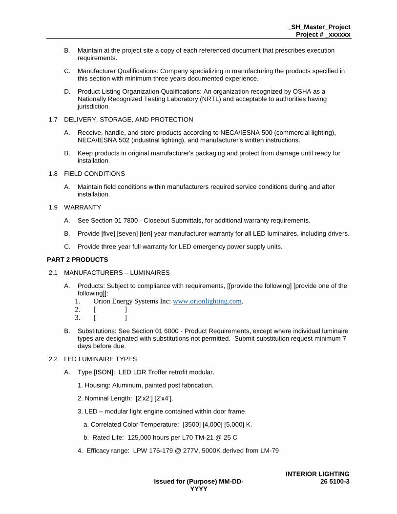
B. Maintain at the project site a copy of each referenced document that prescribes execution requirements.
C. Manufacturer Qualifications: Company specializing in manufacturing the products specified in this section with minimum three years documented experience.
D. Product Listing Organization Qualifications: An organization recognized by OSHA as a Nationally Recognized Testing Laboratory (NRTL) and acceptable to authorities having jurisdiction.
1.7 DELIVERY, STORAGE, AND PROTECTION
A. Receive, handle, and store products according to NECA/IESNA 500 (commercial lighting), NECA/IESNA 502 (industrial lighting), and manufacturer's written instructions.
B. Keep products in original manufacturer's packaging and protect from damage until ready for installation.
1.8 FIELD CONDITIONS
A. Maintain field conditions within manufacturers required service conditions during and after installation.
1.9 WARRANTY
A. See Section 01 7800 - Closeout Submittals, for additional warranty requirements.
B. Provide [five] [seven] [ten] year manufacturer warranty for all LED luminaires, including drivers.
C. Provide three year full warranty for LED emergency power supply units.
PART 2 PRODUCTS
2.1 MANUFACTURERS – LUMINAIRES
A. Products: Subject to compliance with requirements, [[provide the following] [provide one of the following]]:
1. Orion Energy Systems Inc: www.orionlighting.com.
2. [ ]
3. [ ]
B. Substitutions: See Section 01 6000 - Product Requirements, except where individual luminaire types are designated with substitutions not permitted. Submit substitution request minimum 7 days before due.
2.2 LED LUMINAIRE TYPES
A. Type [ISON]: LED LDR Troffer retrofit modular.
1. Housing: Aluminum, painted post fabrication.
2. Nominal Length: [2’x2’] [2’x4’].
3. LED – modular light engine contained within door frame.
a. Correlated Color Temperature: [3500] [4,000] [5,000] K.
b. Rated Life: 125,000 hours per L70 TM-21 @ 25 C
4. Efficacy range: LPW 176-179 @ 277V, 5000K derived from LM-79

26 5100-4 Issued for (Purpose) MM-DD-
YYYY
5. Voltage: Universal 120-277 V.
6. Total Harmonic Distortion: ≤ 20%
7. Driver: [Non-dimming, Full dimming].
8. Nominal Lumens: Class [2,000lm][4000lm] [3000lm] [4,000lm] [6,000lm] [8000lm]
9. Ambient Operation Range: (0C to 40C).
10. Integrated battery pack option
B. Type [APOLLO]: LED Troffer retrofit 1x4 flat.
1. Housing: Aluminum, painted post fabrication.
2. Nominal Length: 1’x4’.
3. LED – modular light engine contained within door frame.
a. Correlated Color Temperature: [3000] [3500] [4,000] [5,000] K.
b. Rated Life: 125000 hours per L70 TM-21 @ 25 C
4. Efficacy range: LPW 176-179 @ 277V, 5000K derived from LM-79
5. Voltage: Universal 120-277 V.
6. Total Harmonic Distortion: ≤ 20%
7. Driver: [Full-dimming].
8. Nominal Lumens: Class [2,000lm] [4000lm]
9. Ambient Operation Range: (0C to 40C).
10. Integrated battery pack option
C. Type [APOLLO]: LED Troffer retrofit L-Series flat.
1. Housing: Aluminum, painted post fabrication.
2. Nominal Length: [2’x2’] [2’x4’].
3. LED – modular light engine contained within door frame.
a. Correlated Color Temperature: [3000] [3500] [4,000] [5,000] K.
b. Rated Life: 125000 hours per L70 TM-21 @ 25 C
4. Efficacy range: LPW 176-179 @ 277V, 5000K derived from LM-79
5. Voltage: Universal 120-277 V.
6. Total Harmonic Distortion: ≤ 20%
7. Driver: [Full-dimming].
8. Nominal Lumens: Class [4000lm] [5,000lm] [7,000lm] [9000lm]
9. Ambient Operation Range: (0C to 40C).
10. Integrated battery pack option

_SH_Master_Project Project # _xxxxxx
INTERIOR LIGHTING Issued for (Purpose) MM-DD-
YYYY 26 5100-5
D. Type [APOLLO]: LED Troffer retrofit L-Series 3 Panel.
1. Housing: Aluminum, painted post fabrication.
2. Nominal Length: [2’x2’] [2’x4’].
3. LED – modular light engine contained within door frame.
a. Correlated Color Temperature: [3000] [3500] [4,000] [5,000] K.
b. Rated Life: 125000 hours per L70 TM-21 @ 25 C
4. Efficacy range: LPW 176-179 @ 277V, 5000K derived from LM-79
5. Voltage: Universal 120-277 V.
6. Total Harmonic Distortion: ≤ 20%
7. Driver: [Full-dimming].
8. Nominal Lumens: Class [4000lm] [5,000lm]
9. Ambient Operation Range: (0C to 40C).
10. Integrated battery pack option.
E. Type [APOLLO]: LED Troffer retrofit L-Series Contour.
1. Housing: Aluminum, painted post fabrication.
2. Nominal Length: [2’x2’] [2’x4’].
3. LED – modular light engine contained within door frame.
a. Correlated Color Temperature: [3000] [3500] [4,000] [5,000] K.
b. Rated Life: 125000 hours per L70 TM-21 @ 25 C
4. Efficacy range: LPW 176-179 @ 277V, 5000K derived from LM-79
5. Voltage: Universal 120-277 V.
6. Total Harmonic Distortion: ≤ 20%
7. Driver: [Full-dimming].
8. Nominal Lumens: Class [3500lm] [4,100lm]
9. Ambient Operation Range: (0C to 40C).
10. Integrated battery pack option.
F. Type [APOLLO]: LED Troffer retrofit F-Series Contour.
1. Housing: Aluminum, painted post fabrication.
2. Nominal Length: [2’x2’] [2’x4’].
3. LED – modular light engine contained within door frame.
a. Correlated Color Temperature: [3000] [3500] [4,000] [5,000] K.
b. Rated Life: 125000 hours per L70 TM-21 @ 25 C
26 5100-6 Issued for (Purpose) MM-DD-
YYYY
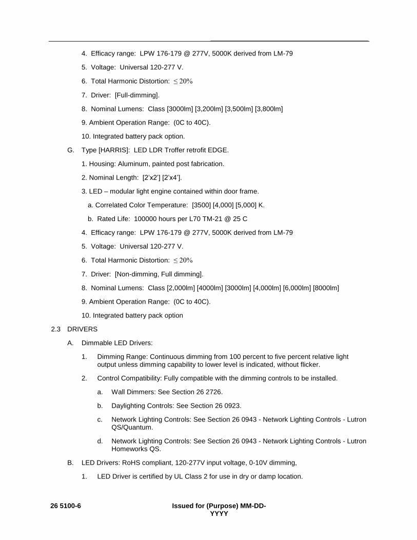
4. Efficacy range: LPW 176-179 @ 277V, 5000K derived from LM-79
5. Voltage: Universal 120-277 V.
6. Total Harmonic Distortion: ≤ 20%
7. Driver: [Full-dimming].
8. Nominal Lumens: Class [3000lm] [3,200lm] [3,500lm] [3,800lm]
9. Ambient Operation Range: (0C to 40C).
10. Integrated battery pack option.
G. Type [HARRIS]: LED LDR Troffer retrofit EDGE.
1. Housing: Aluminum, painted post fabrication.
2. Nominal Length: [2’x2’] [2’x4’].
3. LED – modular light engine contained within door frame.
a. Correlated Color Temperature: [3500] [4,000] [5,000] K.
b. Rated Life: 100000 hours per L70 TM-21 @ 25 C
4. Efficacy range: LPW 176-179 @ 277V, 5000K derived from LM-79
5. Voltage: Universal 120-277 V.
6. Total Harmonic Distortion: ≤ 20%
7. Driver: [Non-dimming, Full dimming].
8. Nominal Lumens: Class [2,000lm] [4000lm] [3000lm] [4,000lm] [6,000lm] [8000lm]
9. Ambient Operation Range: (0C to 40C).
10. Integrated battery pack option
2.3 DRIVERS
A. Dimmable LED Drivers:
1. Dimming Range: Continuous dimming from 100 percent to five percent relative light output unless dimming capability to lower level is indicated, without flicker.
2. Control Compatibility: Fully compatible with the dimming controls to be installed.
a. Wall Dimmers: See Section 26 2726.
b. Daylighting Controls: See Section 26 0923.
c. Network Lighting Controls: See Section 26 0943 - Network Lighting Controls - Lutron QS/Quantum.
d. Network Lighting Controls: See Section 26 0943 - Network Lighting Controls - Lutron Homeworks QS.
B. LED Drivers: RoHS compliant, 120-277V input voltage, 0-10V dimming,
1. LED Driver is certified by UL Class 2 for use in dry or damp location.

_SH_Master_Project Project # _xxxxxx
INTERIOR LIGHTING Issued for (Purpose) MM-DD-
YYYY 26 5100-7
2. LED Driver has a Class A sound rating.
3. LED Driver has a minimum operating ambient temperature of -40C.
4. LED Driver has a life expectancy of 50,000 hours at Tcase of ≤ 70C.
5. LED Driver tolerates sustained open circuit and short circuit output conditions without damage.
6. LED Driver complies with FCC rules and regulations, as per Title 47 CFR Part 15 Non-Consumer (Class A).
2.4 LED EMERGENCY POWER SUPPLY UNITS
A. Description: Self-contained LED emergency power supply units suitable for use with indicated luminaires, complying with NFPA 101 and all applicable state and local codes, and listed and labeled as complying with UL 924.
B. The unit shall be provided complete with an illuminated push to test switch. The emergency driver system shall be UL class 2 certified in accordance with UL 1310 and shall be UL listed for use in damp locations and in enclosed and gasketed fixtures with a temperature range of 0° to 55° C.
C. Operation: Upon interruption of normal power source, solid-state control automatically switches connected lamp(s) to the LED emergency power supply for minimum of 90 minutes of rated emergency illumination, and automatically recharges battery upon restoration of normal power source.
D. Battery: Sealed maintenance-free high-temperature nickel cadmium unless otherwise indicated.
E. The emergency driver shall accommodate an LED load with a forward voltage requirement ranging from 10 to 60 VDC. The output voltage sensing shall be automatic and instantaneous with a resulting, inversely-proportional current to maintain constant power to the LED array with an output tolerance of +/- 3%. The unit shall supply the rated load for a minimum of 1 1/2 hours or to 87 1/2% of rated battery terminal voltage. The output power to the LED load during emergency operation shall be held constant 10 watts from minute one throughout the entire emergency run time resulting in no loss or degradation of the light source during emergency operation.
F. The unit shall be furnished with an electronic, AC-lockout circuit which will connect the battery when the AC circuit is activated, and an electronic brownout circuit which will enable a transfer to emergency operation when utility power dips below an acceptable level. Maximum remote mounting distance of the emergency driver shall be 50-feet.
G. The AC input shall be a two-wire, universal voltage capable 120 thru 277 VAC, 50/60 Hz and be UL Classified to Category Control Number (CCN) FTBR, Emergency Lighting and Power Equipment, and FTBV, Emergency Light-Emitting-Diode Drivers for field installation. Maximum input power of the emergency driver shall be 3.7 watts.
H. The unit charger shall consist of a two-stage charging system which samples the battery in relation to its temperature, state of charge and input voltage fluctuations. The charger shall be current limited, temperature compensated, short-circuit protected with reverse polarity protection. A low voltage battery disconnect (LVD) circuit shall be provided and will disconnect the load and circuitry from the battery when it reaches approximately 80 to 85% of its nominal terminal voltage, preventing a non-recoverable, deep-discharge condition as well as equipment initialization failure when utility power is restored. The unit shall achieve a full recharge in 24-hours.

26 5100-8 Issued for (Purpose) MM-DD-
YYYY
I. Accessories:
1. Provide compatible accessory remote combination test switch/indicator light.
2.5 ACCESSORIES
A. Stems for Suspended Luminaires: Steel tubing, minimum 1/2" size, factory finished to match luminaire or field-painted as directed.
B. Threaded Rods for Suspended Luminaires: Zinc-plated steel, minimum 1/4" size, field-painted as directed.
PART 3 EXECUTION
3.1 EXAMINATION
A. Verify that field measurements are as shown on the drawings.
B. Verify that outlet boxes are installed in proper locations and at proper mounting heights and are properly sized to accommodate conductors in accordance with NFPA 70.
C. Verify that suitable support frames are installed where required.
D. Verify that branch circuit wiring installation is completed, tested, and ready for connection to luminaires.
E. Verify that conditions are satisfactory for installation prior to starting work.
3.2 PREPARATION
A. Provide extension rings to bring outlet boxes flush with finished surface.
B. Clean dirt, debris, plaster, and other foreign materials from outlet boxes.
3.3 INSTALLATION
A. Coordinate locations of outlet boxes provided under Section 26 0537 as required for installation of luminaires provided under this section.
B. Install products according to manufacturer's instructions.
C. Install luminaires securely, in a neat and workmanlike manner, as specified in NECA 1 (general workmanship) and NECA 500 (commercial lighting).
D. Install luminaires plumb and square and aligned with building lines and with adjacent luminaires.
E. Suspended Luminaires:
1. Unless otherwise indicated, specified mounting heights are to bottom of luminaire.
2. Install using the suspension method indicated, with support lengths and accessories as required for specified mounting height.
3. Install not less than 0.1125 galvanized steel support wires. Attach wires to building structure above luminaire and attach wires to luminaire at not less than 4 symmetrically spaced points.
4. Unless otherwise indicated, support pendants from swivel hangers.
F. Seismic bracing shall be per 26 0548 Vibration and Seismic Controls for Electrical Systems.

_SH_Master_Project Project # _xxxxxx
INTERIOR LIGHTING Issued for (Purpose) MM-DD-
YYYY 26 5100-9
G. Install accessories furnished with each luminaire.
H. Bond products and metal accessories to branch circuit equipment grounding conductor.
I LED Emergency Power Supply Units:
1. For field-installed units, install inside luminaire unless otherwise indicated. Where installation inside luminaire is not possible, install on top of luminaire.
2. Unless otherwise indicated, connect unit to unswitched power from same circuit feeding normal ballast(s) in luminaire. Bypass local switches, contactors, or other lighting controls.
3.4 FIELD QUALITY CONTROL
A. See Section 01 4000 - Quality Requirements, for additional requirements.
B. Inspect each product for damage and defects.
C. Operate each luminaire after installation and connection to verify proper operation.
D. Test LED emergency power supply units to verify proper operation upon loss of normal power supply.
E. Correct wiring deficiencies and repair or replace damaged or defective products. Repair or replace excessively noisy ballasts as determined by Architect/Engineer.
3.5 ADJUSTING
A. Aim and position adjustable luminaires to achieve desired illumination as indicated or as directed by Architect/Engineer. Secure locking fittings in place.
3.6 CLEANING
A. Clean surfaces according to NECA 500 (commercial lighting), NECA 502 (industrial lighting), and manufacturer's instructions to remove dirt, fingerprints, paint, or other foreign material and restore finishes to match original factory finish.
3.7 CLOSEOUT ACTIVITIES
A. See Section 01 7800 - Closeout Submittals, for closeout submittals.
B. See Section 01 7900 - Demonstration and Training, for additional requirements.
C. Just prior to Substantial Completion, replace all lamps that have failed.
3.8 PROTECTION
A. Protect installed luminaires from subsequent construction operations.
END OF SECTION

26 5100-10 Issued for (Purpose) MM-DD-
YYYY

© 2016 Orion Energy Systems, Inc. All rights reserved. The Orion logo, ISON™, APOLLO®, HARRIS and InteLite® product names are registered trademarks of Orion Energy Systems. All other trademarks are the property of their respective owners.800.660.9340 | orionlighting.com
ISON™ LDR® TROFFER RETROFIT MODULAR
LDRM1Features and SpecificationsApplications Retrofits existing 2’x2’ and 2’x4’ fluorescent troffers to LED. Industry’s first Patented LED troffer retrofit contained within the door frame.
Features • Patent pending modular light engine
allows for color temperature and light output upgrades in the field.
• Future-proof, interchangeable design delivers the benefits of replaceable LED tubes without safety risks.
• Installs in as little as 2 minutes.
Certification & Listings• Patented LDR® design.• UL Classified. • Design Lights Consortium® qualified.• Visit the DLC QPL for listed models.
ConstructionAluminum frame. Required mounting brackets adapt the LDRM1 to fit nearly all existing troffers.
Optics/LensMatte finish polycarbonate contour lens eliminates glare and provides even light distribution.
Electrical 120-277v. Quick connect system.
Ambient Operating Range32°F to 104°F (0°C to 40°C ).
Rated Life125,000 hours.
FinishPowder coated white.
WarrantyOrion LED fixtures are covered by a ten-year limited warranty. Accessories and individual components are covered by separate OEM supplier warranties.
Ordering InformationSeries Nominal
LumensVolt-age
Driver Type CRI; Color Temp.
Fixture Size
Lens Material
Bracket Type
Additional Options
LDRM1= LED Retrofit Modular Gen1
2x2A1= 2000lm
B1= 4000lm
2x4D1= 3000lm
E1= 4000lm
F1= 6000lm
G1= 8000lm1
UNV= 120-277v
FDXX= Full Dimming 0-10v2
FDHB= Lutron Hi-lume dim to 1%, Fade to Black
FDH1= Lutron Hi-lume dim to 1%
FDH2= Lutron Hi-lume dim to 1% 2wire 120v
FDH3= Lutron Hi-lume dim to 1% 3wire 120-277v
FD55= Lutron 5-series dim to 5%
835= 80CRI, 3500K
840= 80CRI, 4000k
850= 80CRI, 5000K
22= 2x2
24= 2x4
M= Opaque Matte
ST= Standard
PL= Plenum
LF= Lift
-BB= Battery Back-up*
-DD= Dial Dimmer
-EN= Enlighted
Ordering Information ExampleSeries Nominal
LumensVoltage Driver
TypeCRI; Color Temp.
Fixture Size
Lens Material
Bracket Type
Additional Options
LDRM1 D1 UNV FDXX 835 24 M ST -BB
Easy upgradeable Patent pending modular light engine.
U.S.PAT.

© 2016 Orion Energy Systems, Inc. All rights reserved. The Orion logo, ISON™, APOLLO®, HARRIS and InteLite® product names are registered trademarks of Orion Energy Systems. All other trademarks are the property of their respective owners.800.660.9340 | orionlighting.com
ISON™ LDR® TROFFER RETROFIT MODULAR
LDRM1Performance Information3
Rev. 160428
Series Lumen Code
Actual Lumens
Fixture Size
Lumens Per Watt
Light Output CCT CRI Input
Voltage
Input Power (watts)
Input Current
Power Factor
LDRM1= LED Retrofit Modular Gen1
A1 2000 2x2 104 2182 lm 4000K >80 120 21 0.18 0.99
B1 4000 2x2 103 3617 lm 4000K >80 120 35 0.29 0.99
D1 3000 2x4 107 3097 lm 4000K >80 120 29 0.24 0.99
E1 4000 2x4 126 4157 lm 4000K >80 120 33 0.28 0.99
F1 6000 2x4 118 5541 lm 4000K >80 120 47 0.39 0.99
G1 8000 2x4 123 7744 lm 4000K >80 120 63 0.53 0.99
Physical InformationSize Length Width Depth4 Weight
2x4” 46.75” 20.5” 3.125” 11 lbs.
2x2” 22.75” 20.5” 3.125” 6 lbs.
Photometrics
Fixture Options – Factory Installed
A1 2x2 3500K
D1 2x4 3500K
-BB= Battery Backup
-DD= Dial Dimmer
-EN= Enlighted5
SC= Seismic cable
Additional Specification Information1 G1 not available for Lutron dimming options or other sensor and control options2 FDXX 0-10v driver configurations are compatible with most third party control systems3 Actual performance may vary by up to ±10% of values listed4 Depth varies by model; dependent on driver selection5 Sensor monitors occupancy, daylight, and temperature and communicates data to gateway wireless.
Modular Design Feature
Body features interchangeable modular design. Module installs in less than 1 minute.
Patent pending modular light engine.
Accessories – Sold Separately

© 2016 Orion Energy Systems, Inc. All rights reserved. The Orion logo, ISON™, APOLLO®, HARRIS and InteLite product names are registered trademarks of Orion Energy Systems. All other trademarks are the property of their respective owners. 800.660.9340 | orionlighting.com
APOLLO® TROFFER RETROFIT
LDR: F-Series Contour
PATENT|PENDING
Features and SpecificationsApplications Retrofits existing 2’x2’ and 2’x4’ fluorescent troffers to LED in as little as 1 minute. Industry’s first LED troffer retrofit contained within the door frame.
ConstructionAluminum frame. LDR fits most existing fluorescent troffer fixtures with either prismatic lens or parabolic louvers. Required mounting brackets adapt the LDR to fit nearly all existing troffers.
Certification & Listings• UL Classified. • DesignLights Consortium® qualified.• Visit the DLC QPL for listed models.
Electrical120-277v. Hardwired fixture. Finger board arrays with optic. LED drivers are available in various dimming formats.
LensMatte finish polycarbonate contour lens provides glare diffusion in the work environment.
FinishPowder coated white.
Rated Life125,000 hours L70 TM-21 @ 25°C.
WarrantyOrion LED fixtures are covered by a five-year limited warranty. Accessories and individual components are covered by separate OEM supplier warranties.
Required Ordering Information
2Select ____
Nominal Lumens
030L 3,000 lm (2x2 only)
032L 3,200 lm (2x4 only)
035L 3,500 lm (2x2 only)
038L 3,800 lm (2x4 only)
1Select ___
Series
LDR LED TrofferRetrofit
4Select ___
Voltage
UNV 120-277v
6 Select ___
CRI; Color Temperature
850 80 CRI; 5000K
840 80 CRI; 4000K
835 80 CRI; 3500K
830 80 CRI; 3000K
3Select __
Array Type
FO Fingerboard with optic
5Select ___
Dimming (Hyperlinks lead to vendor data sheets)
FDX 0-10v Full Dimming.
FDHLutron Hi-Lume Dim to 1%, Fade to Black.
FD1 Lutron Hi-Lume Dim to 1%.
FD2Lutron Hi-Lume Dim to 1%., 2-wire, 120v.
FD3Lutron Hi-Lume Dim to 1%., 3-wire, 122-277v.
FD5 Lutron 5-series, Dim to 5%.
LDR
9Select __
Lens Style
CT Contour
7Select __
Fixture Size
22 2’x2’
24 2’x4’
8Select __
# of Panels
1P 1 Panel
10Select _
Lens Material
M Matte
UNV
12Select ___
Additional Options
-BB Battery Back-up*
-DT Daintree Wireless**
-DD Dial Dimmer
11Select __
Bracket Type
ST Standard
PL Plenum
LF Lift
M
1P CT
FO
© 2016 Orion Energy Systems, Inc. All rights reserved. The Orion logo, ISON™, APOLLO®, HARRIS and InteLite product names are registered trademarks of Orion Energy Systems. All other trademarks are the property of their respective owners. 800.660.9340 | orionlighting.com
APOLLO® TROFFER RETROFIT
LDR: F-Series Contour
Rev. 160308
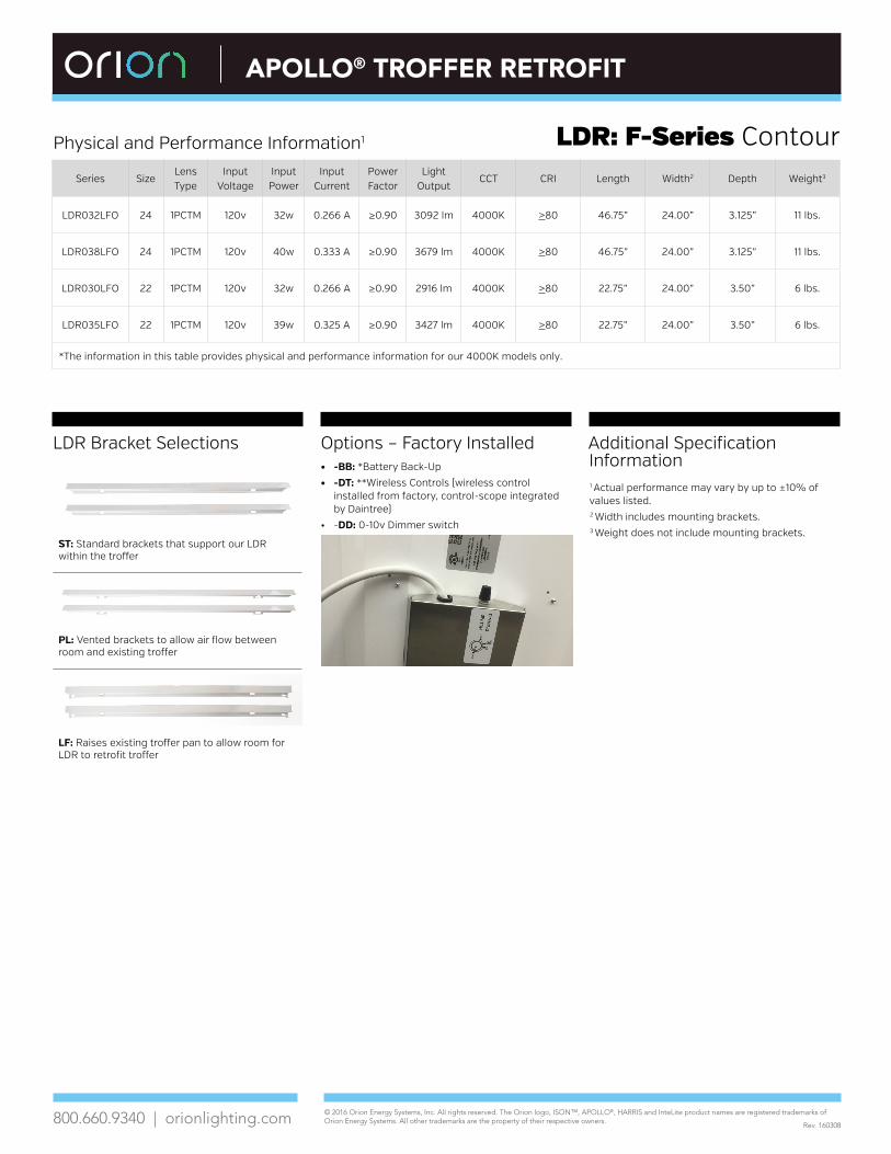
Additional Specification Information1 Actual performance may vary by up to ±10% of values listed. 2 Width includes mounting brackets.3 Weight does not include mounting brackets.
Physical and Performance Information1
Series SizeLens Type
Input Voltage
Input Power
Input Current
Power Factor
Light Output
CCT CRI Length Width2 Depth Weight3
LDR032LFO 24 1PCTM 120v 32w 0.266 A ≥0.90 3092 lm 4000K >80 46.75” 24.00” 3.125” 11 lbs.
LDR038LFO 24 1PCTM 120v 40w 0.333 A ≥0.90 3679 lm 4000K >80 46.75” 24.00” 3.125” 11 lbs.
LDR030LFO 22 1PCTM 120v 32w 0.266 A ≥0.90 2916 lm 4000K >80 22.75” 24.00” 3.50” 6 lbs.
LDR035LFO 22 1PCTM 120v 39w 0.325 A ≥0.90 3427 lm 4000K >80 22.75” 24.00” 3.50” 6 lbs.
*The information in this table provides physical and performance information for our 4000K models only.
LDR Bracket Selections
ST: Standard brackets that support our LDR within the troffer
PL: Vented brackets to allow air flow between room and existing troffer
LF: Raises existing troffer pan to allow room for LDR to retrofit troffer
Options – Factory Installed• -BB: *Battery Back-Up
• -DT: **Wireless Controls (wireless control installed from factory, control-scope integrated by Daintree)
• -DD: 0-10v Dimmer switch

© 2015 Orion Energy Systems, Inc. All rights reserved. The Orion logo, ISON™, APOLLO®, HARRIS and InteLite product names are registered trademarks of Orion Energy Systems. All other trademarks are the property of their respective owners. 800.660.9340 | orionlighting.com
APOLLO® TROFFER RETROFIT
LDR: L-Series FlatFeatures and SpecificationsApplications Retrofits existing 2’ x 4’ and 2’ x 2’ fluorescent troffers to LED in as little as 1 minute. Industry’s first LED troffer retrofit contained within the door frame.
ConstructionAluminum frame. LDR fits most existing fluorescent troffer fixtures with either prismatic lens or parabolic louvers. Required mounting brackets adapt the LDR to fit nearly all existing troffers.
Certification & Listings• UL Classified.
Electrical120-277v. Hardwired fixture. Linear arrays.
LensMatte finish lens provides glare diffusion in the work environment.
FinishPowder coated white.
Rated Life125,000 hours.
WarrantyOrion LED fixtures are covered by a five-year limited warranty. Accessories and individual components are covered by separate OEM supplier warranties.
PATENT|PENDING
Required Ordering Information
2Select ____
Nominal Lumens
040L 4,000 lm
050L 5,000 lm
070L 7,000 lm
090L 9,000 lm*
*090L available in 2’ x 4’ only.
1Select ___
Series
LDR LED Troffer Retrofit
4Select ___
Voltage
UNV 120-277v
6 Select ___
CRI; Color Temperature
850 80 CRI; 5000K
840 80 CRI; 4000K
835 80 CRI; 3500K
830 80 CRI; 3000K
3Select _
Array Type
L Linear
5Select ___
Dimming
FDX Full Dimming
LDR
9Select __
Lens Style
FL Flat
7Select __
Fixture Size
22 2’x2’
24 2’x4’
8Select __
# of Panels
1P 1 Panel
10Select __
Lens Material
PM Prismatic
UNV
12Select ______
Additional Options
-BB Battery Back-up*
-DT Daintree Wireless**
-DD Dial Dimmer
11Select _ _
Bracket Type
ST Standard
PL Plenum
LF Lift
L
FDX
FL1P
Options• *Battery Back-Up (installed
from factory)
• **Wireless Controls (wireless control installed from factory, control-scope integrated by Daintree)
• 0-10v Dimmer switch (sold separately)

© 2015 Orion Energy Systems, Inc. All rights reserved. The Orion logo, ISON™, APOLLO®, HARRIS and InteLite product names are registered trademarks of Orion Energy Systems. All other trademarks are the property of their respective owners. 800.660.9340 | orionlighting.com
APOLLO® TROFFER RETROFIT
LDR: L-Series Flat
Rev. 160412
Additional Specification Information:1Visit the DLC QPL for a list of models qualified.2Actual performance may vary by up to ±10% of values listed. 3Width includes mounting brackets.4Weight does not include mounting brackets.
Physical and Performance Information2
PhotometricsVisit oriolighting.com for all .IES files
Series Size Lens TypeInput
VoltageInput Power
Input CurrentPower Factor
Light Output
CCT CRI Length Width3 Depth Weight4
LDR040LL 24 1PFLPM 120v 33w 0.275 A >0.90 4106 lm 4000K >80 46.75” 24.00” 3.00” 11 lbs.
LDR050LL 24 1PFLPM 120v 45w 0.375 A >0.90 5178 lm 4000K >80 46.75” 24.00” 3.00” 11 lbs.
LDR040LL 22 1PFLPM 120v 35w 0.291 A >0.90 3970 lm 4000K >80 22.75” 24.00” 3.00” 6 lbs.
LDR050LL 22 1PFLPM 120v 47w 0.391 A >0.90 4841 lm 4000K >80 22.75” 24.00” 3.00” 6 lbs.
LDR070LL 24 1PFLPM 120v 57w 0.475 A >0.90 6906 lm 4000K >80 46.75” 24.00” 3.00” 11 lbs.
LDR090LL 24 1PFLPM 120v 78w 0.65 A >0.90 8643 lm 4000K >80 46.75” 24.00” 3.00” 11 lbs.
LDR070LL 22 1PFLPM 120v 67w 0.558 A >0.90 7427 lm 4000K >80 22.75” 24.00” 3.00” 6 lbs.
*The information in this table provides physical and performance information for our 4000K models only.
2x4 5000K 070L
LDR Bracket Type Description
Bracket Type Description
ST Standard brackets that support our LDR within the troffer
PL Vented brackets to allow air flow be-tween room and existing troffer
LF Raises existing troffer pan to allow room for LDR to retrofit troffer
Installation StepsStep Procedure Time
1 Turn off power; remove existing lens or louver 0:00-0:11
2 Remove existing lamps and ballast cover, then disconnect power 0:11-0:40
3 Install supplied brackets and then the completely assembled LDR in bracket holes 0:40-1:12
4 Reconnect wiring to LDR 1:12-1:23
5 Close the LDR lens and secure latches shut 1:23-1:35

© 2015 Orion Energy Systems, Inc. All rights reserved. The Orion logo, ISON™, APOLLO®, Harris and InteLite product names are registered trademarks of Orion Energy Systems. All other trademarks are the property of their respective owners.800.660.9340 | orionlighting.com
APOLLO® TROFFER RETROFIT
LDR: L Series Features and SpecificationsApplications Retrofits existing 1’ x 4’ fluorescent troffers to LED in as little as 1 minute. Industry’s first LED troffer retrofit contained within the door frame.
Certification & Listings• UL Classified.
Construction Aluminum frame. LDR fits most existing fluorescent troffer fixtures with either prismatic lens or parabolic louvers. Required mounting brackets adapt the LDR to fit nearly all existing troffers.
Electrical 120-277v. Hardwired fixture.
Rated Life125,000 hours.
LensMatte finish lens provides glare diffusion.
FinishPowder coated white.
WarrantyOrion LED APOLLO class fixtures are covered by a five-year limited warranty. Accessories and individual components are covered by separate OEM supplier warranties.
Ordering Information
1x4 Flat
OptionsPATENT|PENDING
1Select ___
Series
LDR LED Troffer Retrofit
4Select ___
Voltage
UNV 120-277v
6 Select ___
Color Temperature
850 80 CRI; 5000K
840 80 CRI; 4000K
835 80 CRI; 3500K
830 80 CRI; 3000K
3Select _
Array
L Linear
5Select ___
Dimming
FDX Full Range Dimming
LDR 2Select ____
Nominal Lumens
020L 2000 lm
040L 4000 lm
11Select __________
Bracket
ST Standard Steel Brackets
PLBrackets for Plenum Rated Ceilings
LF Lift Bracket
12*Select __________
Wireless Controls
(blank) No Wireless Controls
-DT Daintree Controls
-0-10v Dimmer switch (sold separately)
- Wireless Controls (12*wireless control installed from factory, control-scope integrated by Daintree)
13Select __________
Seismic Cable Option
(blank) No Cable
-SC Seismic Cable
L
UNV FDX
7Select __
Fixture Size
14 1’ x 4’
14 8Select __
Panel
1P 1 Panel
1P 9Select _ _
Lens Type
FL Flat
FL
10Select _ _
Lens Finish
M Matte
M
© 2015 Orion Energy Systems, Inc. All rights reserved. The Orion logo, ISON™, APOLLO®, Harris and InteLite product names are registered trademarks of Orion Energy Systems. All other trademarks are the property of their respective owners.800.660.9340 | orionlighting.com
APOLLO® TROFFER RETROFIT
Rev. 160412
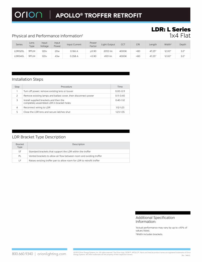
LDR: L Series Physical and Performance Information2 1x4 Flat
Installation Steps
LDR Bracket Type Description
Bracket Type
Description
ST Standard brackets that support the LDR within the troffer
PL Vented brackets to allow air flow between room and existing troffer
LF Raises existing troffer pan to allow room for LDR to retrofit troffer
Additional Specification Information:1Actual performance may vary by up to ±10% of values listed.2Width includes brackets.
SeriesLens Type
Input Voltage
Input Power
Input CurrentPower Factor
Light Output CCT CRI Length Width2 Depth
LDR020L 1PFLM 120v 20w 0.166 A >0.90 2053 lm 4000K >80 47.25” 12.00” 3.0”
LDR040L 1PFLM 120v 43w 0.358 A >0.90 4101 lm 4000K >80 47.25” 12.00” 3.0”
Step Procedure Time
1 Turn off power; remove existing lens or louver 0:00-0:11
2 Remove existing lamps and ballast cover, then disconnect power 0:11-0:40
3 Install supplied brackets and then the completely assembled LDR in bracket holes
0:40-1:12
4 Reconnect wiring to LDR 1:12-1:23
5 Close the LDR lens and secure latches shut 1:23-1:35

© 2015 Orion Energy Systems, Inc. All rights reserved. The Orion logo, ISON™, APOLLO®, HARRIS and InteLite product names are registered trademarks of Orion Energy Systems. All other trademarks are the property of their respective owners. 800.660.9340 | orionlighting.com
APOLLO® TROFFER RETROFIT
LDR: L-Series 3 Panel
PATENT|PENDING
Features and SpecificationsApplications Retrofits existing 2’ x 4’ and 2’ x 2’ fluorescent troffers to LED in as little as 1 minute. Industry’s first LED troffer retrofit contained within the door frame.
ConstructionAluminum frame. LDR fits most existing fluorescent troffer fixtures with either prismatic lens or parabolic louvers. Required mounting brackets adapt the LDR to fit nearly all existing troffers.
Certification & Listings• UL Classified. • DesignLights Consortium® qualified.• Visit the DLC QPL for listed models.
Electrical120-277v. Hardwired fixture. Linear arrays.
LensMatte finish lens provides glare diffusion in the work environment.
FinishPowder coated white.
Rated Life125,000 hours L70 TM-21 @ 25°C.
WarrantyOrion LED fixtures are covered by a five-year limited warranty. Accessories and individual components are covered by separate OEM supplier warranties.
Required Ordering Information
2Select ____
Nominal Lumens
040L 4,000 lm
050L 5,000 lm
1Select ___
Series
LDR LED TrofferRetrofit
4Select ___
Voltage
UNV 120-277v
6 Select ___
CRI; Color Temperature
850 80 CRI; 5000K
840 80 CRI; 4000K
835 80 CRI; 3500K
830 80 CRI; 3000K
3Select _
Array Type
L Linear
5Select ___
Dimming
FDX Full Dimming
LDR
9Select __
Lens Style
FL Flat
7Select __
Fixture Size
22 2’x2’
24 2’x4’
8Select __
# of Panels
3P 3 Panel
10Select _
Lens Material
M Matte
UNV
12Select ______
Additional Options
-BB Battery Back-up*
-DT Daintree Wireless**
-DD Dial Dimmer
11Select _ _
Bracket Type
ST Standard
PL Plenum
LF Lift
M
FDX
L
3P FL
Options• *Battery Back-Up (installed from factory)
• **Wireless Controls (wireless control installed from factory, control-scope integrated by Daintree)
• 0-10v Dimmer switch (sold separately)

© 2015 Orion Energy Systems, Inc. All rights reserved. The Orion logo, ISON™, APOLLO®, HARRIS and InteLite product names are registered trademarks of Orion Energy Systems. All other trademarks are the property of their respective owners. 800.660.9340 | orionlighting.com
APOLLO® TROFFER RETROFIT
LDR: L-Series 3 Panel
Rev. 151211
Additional Specification Information:1Visit the DLC QPL for a list of models qualified.2Actual performance may vary by up to ±10% of values listed. 3Width includes mounting brackets.4Weight does not include mounting brackets.
Physical and Performance Information2
LDR Bracket Type Description
Bracket Type Description
ST Standard brackets that support our LDR within the troffer
PL Vented brackets to allow air flow be-tween room and existing troffer
LF Raises existing troffer pan to allow room for LDR to retrofit troffer
Installation Steps
Photometrics
Step Procedure Time
1 Turn off power; remove existing lens or louver 0:00-0:11
2 Remove existing lamps and ballast cover, then disconnect power 0:11-0:40
3 Install supplied brackets and then the completely assembled LDR in bracket holes 0:40-1:12
4 Reconnect wiring to LDR 1:12-1:23
5 Close the LDR lens and secure latches shut 1:23-1:35
Visit oriolighting.com for all .IES files
Series SizeLens Type
Input Voltage
Input Power
Input Current
Power Factor
Light Output
CCT CRI Length Width3 Depth Weight4
LDR040LL 24 3PFLM 120v 34w 0.283 A >0.90 3931 lm 4000K >80 46.75” 24.00” 3.00” 11 lbs.
LDR050LL 24 3PFLM 120v 46w 0.383 A >0.90 4949 lm 4000K >80 46.75” 24.00” 3.00” 11 lbs.
LDR040LL 22 3PFLM 120v 35w 0.291 A >0.90 3836 lm 4000K >80 22.75” 24.00” 3.00” 6 lbs.
LDR050LL 22 3PFLM 120v 46w 0.383 A >0.90 4729 lm 4000K >80 22.75” 24.00” 3.00” 6 lbs.
*The information in this table provides physical and performance information for our 4000K models only.
2x4 34w 2x4 46w

© 2016 Orion Energy Systems, Inc. All rights reserved. The Orion logo, ISON™, APOLLO®, HARRIS and InteLite product names are registered trademarks of Orion Energy Systems. All other trademarks are the property of their respective owners. 800.660.9340 | orionlighting.com
5Select ___
Dimming (Hyperlinks lead to vendor data sheets)
FDX 0-10v Full Dimming.
FDHLutron Hi-Lume Dim to 1%, Fade to Black.
FD1 Lutron Hi-Lume Dim to 1%.
FD2Lutron Hi-Lume Dim to 1%., 2-wire, 120v.
FD3Lutron Hi-Lume Dim to 1%., 3-wire, 122-277v.
FD5 Lutron 5-series, Dim to 5%.
APOLLO® TROFFER RETROFIT
LDR: L-Series Contour
PATENT|PENDING
Features and SpecificationsApplications Retrofits existing 2’x2’ and 2’x4’ fluorescent troffers to LED in as little as 1 minute. Industry’s first LED troffer retrofit contained within the door frame.
ConstructionAluminum frame. LDR fits most existing fluorescent troffer fixtures with either prismatic lens or parabolic louvers. Required mounting brackets adapt the LDR to fit nearly all existing troffers.
Certification & Listings• UL Classified. • DesignLights Consortium® qualified.• Visit the DLC QPL for listed models.
Electrical120-277v. Hardwired fixture. Linear arrays. LED drivers are available in various dimming formats.
LensMatte finish polycarbonate contour lens provides glare diffusion in the work environment.
FinishPowder coated white.
Rated Life125,000 hours L70 TM-21 @ 25°C.
WarrantyOrion LED fixtures are covered by a five-year limited warranty. Accessories and individual components are covered by separate OEM supplier warranties.
Required Ordering Information
2Select ____
Nominal Lumens
035L 3,500 lm
041L 4,100 lm
1Select ___
Series
LDR LED TrofferRetrofit
4Select ___
Voltage
UNV 120-277v
6 Select ___
CRI; Color Temperature
850 80 CRI; 5000K
840 80 CRI; 4000K
835 80 CRI; 3500K
830 80 CRI; 3000K
3Select _
Array Type
L Linear
LDR
9Select __
Lens Style
CT Contour
7Select __
Fixture Size
22 2’x2’
24 2’x4’
8Select __
# of Panels
1P 1 Panel
10Select _
Lens Material
M Matte
UNV
12Select ______
Additional Options
-BB Battery Back-up*
-DT Daintree Wireless**
-DD Dial Dimmer
11Select _ _
Bracket Type
ST Standard
PL Plenum
LF Lift
M
1P CT
L

© 2016 Orion Energy Systems, Inc. All rights reserved. The Orion logo, ISON™, APOLLO®, HARRIS and InteLite product names are registered trademarks of Orion Energy Systems. All other trademarks are the property of their respective owners. 800.660.9340 | orionlighting.com
APOLLO® TROFFER RETROFIT
LDR: L-Series Contour
Rev. 160308
Physical and Performance Information1
Photometrics
Series SizeLens Type
Input Voltage
Input Power
Input CurrentPower Factor
Light Output
CCT CRI Length Width2 Depth Weight3
LDR035LL 24 1PCTM 120v 31W 0.258 A ≥0.90 3441 lm 4000K >80 46.75” 24.00” 3.125” 11 lbs.
LDR041LL 24 1PCTM 120v 39W 0.325 A ≥0.90 4059 lm 4000K >80 46.75” 24.00” 3.125” 11 lbs.
LDR035LL 22 1PCTM 120v 32w 0.266 A ≥0.90 3447 lm 4000K >80 22.75” 24.00” 3.125” 6 lbs.
LDR041LL 22 1PCTM 120v 39w 0.325 A ≥0.90 3987 lm 4000K >80 22.75” 24.00” 3.125” 6 lbs.
*The information in this table provides physical and performance information for our 4000K models only.
2x2 32w 2x2 39w
Visit orionlighting.com for all .IES files
LDR Bracket Selections
ST: Standard brackets that support our LDR within the troffer
PL: Vented brackets to allow air flow between room and existing troffer
LF: Raises existing troffer pan to allow room for LDR to retrofit troffer
Options – Factory Installed• -BB: *Battery Back-Up
• -DT: **Wireless Controls (wireless control installed from factory, control-scope integrated by Daintree)
• -DD: 0-10v Dimmer switch
Additional Specification Information1 Actual performance may vary by up to ±10% of values listed. 2 Width includes mounting brackets.3 Weight does not include mounting brackets.
© 2016 Orion Energy Systems, Inc. All rights reserved. The Orion logo, ISON™, APOLLO®, HARRIS and InteLite product names are registered trademarks of Orion Energy Systems. All other trademarks are the property of their respective owners.800.660.9340 | orionlighting.com
HARRIS LDR® TROFFER RETROFIT EDGE
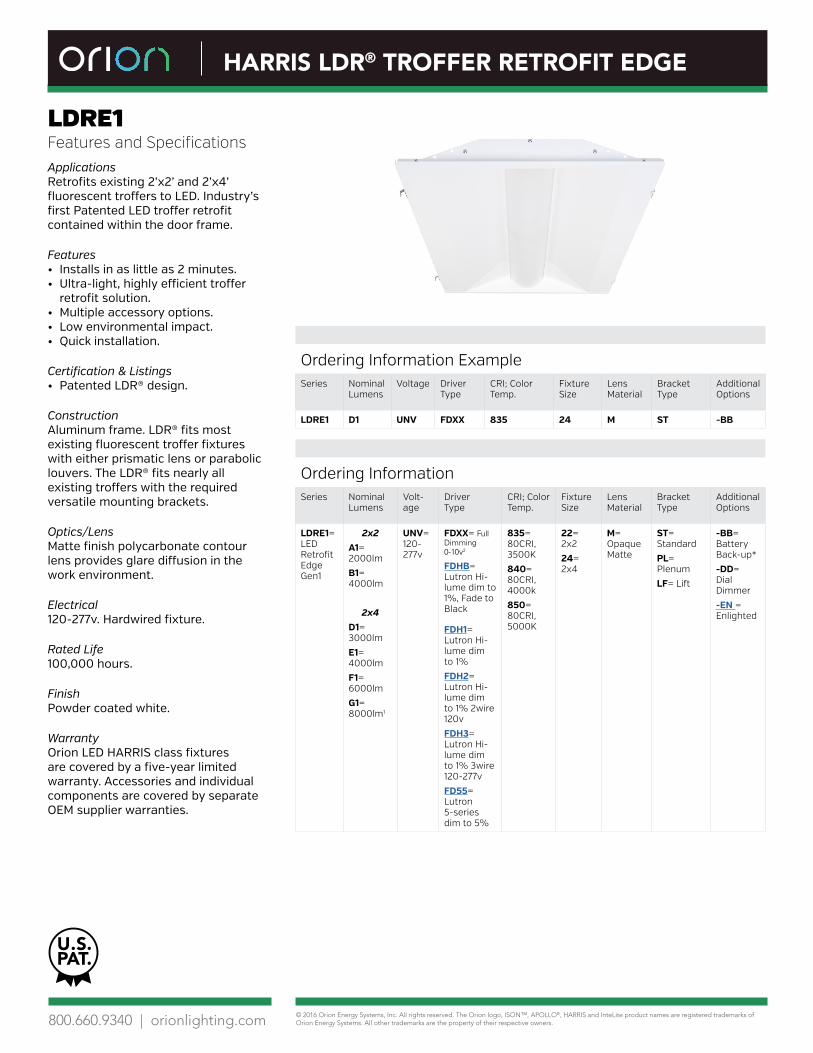
LDRE1 Features and SpecificationsApplications Retrofits existing 2’x2’ and 2’x4’ fluorescent troffers to LED. Industry’s first Patented LED troffer retrofit contained within the door frame.
Features • Installs in as little as 2 minutes.• Ultra-light, highly efficient troffer
retrofit solution.• Multiple accessory options.• Low environmental impact.• Quick installation.
Certification & Listings• Patented LDR® design.
ConstructionAluminum frame. LDR® fits most existing fluorescent troffer fixtures with either prismatic lens or parabolic louvers. The LDR® fits nearly all existing troffers with the required versatile mounting brackets.
Optics/LensMatte finish polycarbonate contour lens provides glare diffusion in the work environment.
Electrical 120-277v. Hardwired fixture.
Rated Life100,000 hours.
FinishPowder coated white.
WarrantyOrion LED HARRIS class fixtures are covered by a five-year limited warranty. Accessories and individual components are covered by separate OEM supplier warranties.
Ordering InformationSeries Nominal
LumensVolt-age
Driver Type
CRI; Color Temp.
Fixture Size
Lens Material
Bracket Type
Additional Options
LDRE1= LED Retrofit Edge Gen1
2x2A1= 2000lm
B1= 4000lm
2x4D1= 3000lm
E1= 4000lm
F1= 6000lm
G1= 8000lm1
UNV= 120-277v
FDXX= Full Dimming 0-10v2
FDHB= Lutron Hi-lume dim to 1%, Fade to Black
FDH1= Lutron Hi-lume dim to 1%
FDH2= Lutron Hi-lume dim to 1% 2wire 120v
FDH3= Lutron Hi-lume dim to 1% 3wire 120-277v
FD55= Lutron 5-series dim to 5%
835= 80CRI, 3500K
840= 80CRI, 4000k
850= 80CRI, 5000K
22= 2x2
24= 2x4
M= Opaque Matte
ST= Standard
PL= Plenum
LF= Lift
-BB= Battery Back-up*
-DD= Dial Dimmer
-EN = Enlighted
Ordering Information ExampleSeries Nominal
LumensVoltage Driver
TypeCRI; Color Temp.
Fixture Size
Lens Material
Bracket Type
Additional Options
LDRE1 D1 UNV FDXX 835 24 M ST -BB
U.S.PAT.

© 2016 Orion Energy Systems, Inc. All rights reserved. The Orion logo, ISON™, APOLLO®, HARRIS and InteLite product names are registered trademarks of Orion Energy Systems. All other trademarks are the property of their respective owners.800.660.9340 | orionlighting.com
HARRIS LDR® TROFFER RETROFIT EDGE
Rev. 160404
LDRE1Physical and Performance Information3
Series Lumen Code
Actual Lumens
Fixture Size
Lumens Per Watt
Light Output CCT CRI Input
Voltage
Input Power (watts)
Input Current
Power Factor
LDRE1= LED Retrofit Edge Gen1
A1 2000 2x2 106 2331 lm 4000K >80 120 22 0.18 >0.99
B1 4000 2x2 109 4145 lm 4000K >80 120 38 0.29 >0.99
D1 3000 2x4 120 3253 lm 4000K >80 120 27 0.25 >0.99
E1 4000 2x4 115 3967 lm 4000K >80 120 35 0.275 >0.99
F1 6000 2x4 126 6047 lm 4000K >80 120 48 0.4 >0.99
G1 8000 2x4 116 7580 lm 4000K >80 120 66 0.516 >0.99
Physical InformationSize Length Width Depth4 Weight
2x4” 46.75” 20.5” 3.125” 11 lbs.
2x2” 22.75” 20.5” 3.125” 6 lbs.
Fixture Options – Factory Installed
Accessories – Sold Separately
Additional Specification Information1 G1 not available for Lutron dimming options or other sensor and control options2 FDXX 0-10v driver configurations are compatible with most third party control systems3 Actual performance may vary by up to ±10% of values listed4 Depth varies by model; dependent on driver selection
-BB= Battery Backup
-DD= Dial Dimmer
SC= Seismic cable
-EN= Enlighted

Issued for (Purpose) MM-DD-YYYY
26 5116-1
SECTION 26 5116
LED HIGH PERFORMANCE HIGH AND LOW BAY INTERIOR LIGHTING
PART 1 GENERAL
1.1 SECTION INCLUDES
A. Interior luminaires.
B. Drivers.
C. Luminaire accessories.
1.2 RELATED REQUIREMENTS
A. Section 26 0537 - Boxes.
B. Section 26 0553 - Identification for Electrical Systems: Identification products and requirements.
C. Section 26 0923 - Lighting Control Devices: Automatic controls for lighting including occupancy sensors, time switches, and daylighting controls.
D. Section 26 0943 - Network Lighting Controls.
E. Section 26 2726 - Wiring Devices: Manual wall switches and wall dimmers.
1.3 REFERENCE STANDARDS
A. 47 CFR 15 - Radio Frequency Devices; Code of Federal Regulations; current edition.
B. IEEE C62.41.2 - Recommended Practice on Characterization of Surges in Low-Voltage (1000 V and less) AC Power Circuits; Institute of Electrical and Electronic Engineers; 2002 (Cor 1, 2012).
C. UL 8750 - Light Emitting Diode (LED) Equipment for Use in Lighting Products; Current Edition, Including All Revisions.
D. IESNA LM-63 - ANSI Approved Standard File Format for Electronic Transfer of Photometric Data and Related Information; Illuminating Engineering Society; 2002 (Reaffirmed 2008).
E. IES LM-79 - Approved Method: Electrical and Photometric Measurements of Solid-State Lighting Products; Illuminating Engineering Society; 2008.
F. IES LM-80 - Approved Method: Measuring Luminous Flux and Color Maintenance of LED Packages, Arrays, and Modules; Illuminating Engineering Society; 2015.
G. NECA 1 - Standard for Good Workmanship in Electrical Construction; National Electrical Contractors Association; 2010.
H. NECA/IESNA 500 - Standard for Installing Indoor Commercial Lighting Systems; National Electrical Contractors Association; 2006.
I. NECA/IESNA 502 - Standard for Installing Industrial Lighting Systems; National Electrical Contractors Association; 2006.
J. NFPA 70 - National Electrical Code; National Fire Protection Association; Most Recent Edition Adopted by Authority Having Jurisdiction, Including All Applicable Amendments and Supplements.

26 5116-2 Issued for (Purpose) MM-DD-YYYY
K. NFPA 101 - Life Safety Code; National Fire Protection Association; 2015.
L. UL 1598 - Luminaires; Current Edition, Including All Revisions.
1.4 ADMINISTRATIVE REQUIREMENTS
A. Coordination:
1. Coordinate the installation of luminaires with mounting surfaces installed under othersections or by others. Coordinate the work with placement of supports, anchors, etc.required for mounting. Coordinate compatibility of luminaires and associated trims withmounting surfaces at installed locations.
2. Coordinate the placement of luminaires with structural members, ductwork, piping,equipment, diffusers, fire suppression system components, and other potential conflictsinstalled under other sections or by others.
3. Notify Architect/Engineer of any conflicts or deviations from the contract documents toobtain direction prior to proceeding with work.
1.5 SUBMITTALS
A. See Section 01 3000 - Administrative Requirements, for submittal procedures.
B. Shop Drawings:
1. Indicate dimensions and components for each luminaire that is not a standard product ofthe manufacturer.
2. Provide photometric calculations where luminaires are proposed for substitution uponrequest.
C. Product Data: Provide manufacturer's standard catalog pages and data sheets includingdetailed information on luminaire construction, dimensions, ratings, finishes, mountingrequirements, listings, service conditions, photometric performance, installed accessories, andceiling compatibility; include model number nomenclature clearly marked with all proposedfeatures.
1. LED Luminaires:
a. Include estimated useful life, calculated based on Energy Star Tm-21 report usingLM-80 test data.
b. Include IES LM-79 test report upon request.
2. Drivers: Include wiring diagrams and list of compatible lamp configurations.
3. LED Chips: Include rated life, color temperature, color rendering index (CRI), and initialand mean lumen output.
D. Certificates for Dimming Drivers: Manufacturer's documentation of compatibility with dimmingcontrols to be installed.
E. Field Quality Control Reports.
F. Operation and Maintenance Data: Instructions for each product including information onreplacement parts.
G. Project Record Documents: Record actual connections and locations of luminaires and anyassociated remote components.

_SH_Master_Project Project # _xxxxxx
Issued for (Purpose) MM-DD-YYYY
INTERIOR LIGHTING 26 5116-3
1.6 QUALITY ASSURANCE
A. Conform to requirements of NFPA 70.
B. Maintain at the project site a copy of each referenced document that prescribes executionrequirements.
C. Manufacturer Qualifications: Company specializing in manufacturing the products specified inthis section with minimum three years documented experience.
D. Product Listing Organization Qualifications: An organization recognized by OSHA as aNationally Recognized Testing Laboratory (NRTL) and acceptable to authorities havingjurisdiction.
1.7 DELIVERY, STORAGE, AND PROTECTION
A. Receive, handle, and store products according to NECA/IESNA 500 (commercial lighting),NECA/IESNA 502 (industrial lighting), and manufacturer's written instructions.
B. Keep products in original manufacturer's packaging and protect from damage until ready forinstallation.
1.8 FIELD CONDITIONS
A. Maintain field conditions within manufacturers required service conditions during and afterinstallation.
1.9 WARRANTY
A. See Section 01 7800 - Closeout Submittals, for additional warranty requirements.
B. Provide [five] [seven] [ten] year manufacturer warranty for all LED luminaires, including drivers.
C. Provide three year full warranty for LED emergency power supply units.
PART 2 PRODUCTS
2.1 MANUFACTURERS – LUMINAIRES
A. Products: Subject to compliance with requirements, [[provide the following] [provide one of thefollowing]]:
1. Orion Energy Systems Inc: www.orionlighting.com.
B. Substitutions: See Section 01 6000 - Product Requirements, except where individual luminairetypes are designated with substitutions not permitted. Submit substitution request minimum 7days before due.
2.2 LUMINAIRE TYPES
A. Type [ISON]: LED high-bay luminaire.
1. Housing: Aluminum, painted post fabrication.
2. Nominal Length: 4 feet.
3. LED – modular interchangeable light engine trays.
a. Correlated Color Temperature: [4,000, 5,000] K.
b. Rated Life: 150,000 hours per L70 TM-21 @ 25 C
4. Efficacy range: LPW 176-179 @ 277V, 5000K derived from LM-79

26 5116-4 Issued for (Purpose) MM-DD-YYYY
5. Light Distribution: [Open Area, Aisle Area].
6. Voltage: [Universal 120-277 V, 347V, 480V].
7. Total Harmonic Distortion: ≤ 20%
8. Driver: [Non-dimming, Full dimming].
9. Nominal Lumens: Class 12,000lm, 16,000lm, 19,000lm, 25,000lm
10. Ambient Operation Range: (-30C to 55C).
11. Sensor: [Integrated, End Mounted], 8-40 ft.
12. Integrated battery pack option
13. OSHA orange paint systems identifier, end caps.
B. Type [APOLLO]: LED high-bay luminaire.
1. Housing: Aluminum, painted post fabrication.
2. Nominal Length: 4 feet.
3. LED – modular interchangeable light engine trays.
a. Correlated Color Temperature: [4,000, 5,000] K.
b. Rated Life: 125,000 hours per L70 TM-21 @ 25 C
4. Efficacy range: LPW 141-152 @ 277V, 5000K derived from LM-79
5. Light Distribution: [Open Area, Aisle Area].
6. Voltage: [Universal 120-277 V, 347V, 480V].
7. Total Harmonic Distortion: ≤ 20%
8. Driver: [Non-dimming, Full dimming].
9. Nominal Lumens: Class 13,000lm, 15,000lm, 18,000lm, 21,000, 27,000lm
10. Ambient Operation Range: (-30C to 55C).
11. Sensor: [Integrated, End Mounted], 8-40 ft.
12. Integrated battery pack option
13. OSHA orange paint systems identifier, end caps.
C. Type [HARRIS]: LED high-bay luminaire.
1. Housing: Aluminum, painted post fabrication.
2. Nominal Length: 4 feet.
3. LED – modular interchangeable light engine trays.
a. Correlated Color Temperature: [4,000, 5,000] K.
b. Rated Life: 100,000 hours per L70 TM-21 @ 25 C
4. Efficacy range: LPW 139-149 @ 277V, 5000K derived from LM-79

_SH_Master_Project Project # _xxxxxx
Issued for (Purpose) MM-DD-YYYY
INTERIOR LIGHTING 26 5116-5
5. Light Distribution: [Open Area, Aisle Area].
6. Voltage: [Universal 120-277 V, 347V, 480V].
7. Total Harmonic Distortion: ≤ 20%
8. Driver: [Non-dimming, Full dimming].
9. Nominal Lumens: Class 13,000lm, 15,000lm, 18,000lm, 21,000lm, 27,000lm
10. Ambient Operation Range: (-20C to 50C).
11. Sensor: [End Mounted], 8-40 ft.
2.3 DRIVERS
A. Dimmable LED Drivers:
1. Dimming Range: Continuous dimming from 100 percent to five percent relative lightoutput unless dimming capability to lower level is indicated, without flicker.
2. Control Compatibility: Fully compatible with the dimming controls to be installed.
a. Wall Dimmers: See Section 26 2726.
b. Daylighting Controls: See Section 26 0923.
c. Network Lighting Controls: See Section 26 0943 - Network Lighting Controls - LutronQS/Quantum.
d. Network Lighting Controls: See Section 26 0943 - Network Lighting Controls - LutronHomeworks QS.
B. LED Drivers: RoHS compliant, 120-277V input voltage, 0-10V dimming,
1. LED Driver is certified by UL Class 2 for use in dry or damp location.
2. LED Driver has a Class A sound rating.
3. LED Driver has a minimum operating ambient temperature of -40C.
4. LED Driver has a life expectancy of 50,000 hours at Tcase of ≤ 70C.
5. LED Driver tolerates sustained open circuit and short circuit output conditions withoutdamage.
6. LED Driver complies with FCC rules and regulations, as per Title 47 CFR Part 15 Non-Consumer (Class A).
2.4 LED EMERGENCY POWER SUPPLY UNITS
A. Description: Self-contained LED emergency power supply units suitable for use with indicatedluminaires, complying with NFPA 101 and all applicable state and local codes, and listed andlabeled as complying with UL 924.
B. The unit shall be provided complete with an illuminated push to test switch. The emergencydriver system shall be UL class 2 certified in accordance with UL 1310 and shall be UL listedfor use in damp locations and in enclosed and gasketed fixtures with a temperature range of 0°to 55° C.
C. Operation: Upon interruption of normal power source, solid-state control automatically switchesconnected lamp(s) to the LED emergency power supply for minimum of 90 minutes of rated

26 5116-6 Issued for (Purpose) MM-DD-YYYY
emergency illumination, and automatically recharges battery upon restoration of normal power source.
D. Battery: Sealed maintenance-free high-temperature nickel cadmium unless otherwiseindicated.
E. The emergency driver shall accommodate an LED load with a forward voltage requirementranging from 10 to 60 VDC. The output voltage sensing shall be automatic and instantaneouswith a resulting, inversely-proportional current to maintain constant power to the LED array withan output tolerance of +/- 3%. The unit shall supply the rated load for a minimum of 1 1/2 hoursor to 87 1/2% of rated battery terminal voltage. The output power to the LED load duringemergency operation shall be held constant 10 watts from minute one throughout the entireemergency run time resulting in no loss or degradation of the light source during emergencyoperation.
F. The unit shall be furnished with an electronic, AC-lockout circuit which will connect the batterywhen the AC circuit is activated, and an electronic brownout circuit which will enable a transferto emergency operation when utility power dips below an acceptable level. Maximum remotemounting distance of the emergency driver shall be 50-feet.
G. The AC input shall be a two-wire, universal voltage capable 120 thru 277 VAC, 50/60 Hz andbe UL Classified to Category Control Number (CCN) FTBR, Emergency Lighting and PowerEquipment, and FTBV, Emergency Light-Emitting-Diode Drivers for field installation. Maximuminput power of the emergency driver shall be 3.7 watts.
H. The unit charger shall consist of a two-stage charging system which samples the battery inrelation to its temperature, state of charge and input voltage fluctuations. The charger shall becurrent limited, temperature compensated, short-circuit protected with reverse polarityprotection. A low voltage battery disconnect (LVD) circuit shall be provided and will disconnectthe load and circuitry from the battery when it reaches approximately 80 to 85% of its nominalterminal voltage, preventing a non-recoverable, deep-discharge condition as well as equipmentinitialization failure when utility power is restored. The unit shall achieve a full recharge in 24-hours.
I. Accessories:
1. Provide compatible accessory remote combination test switch/indicator light.
2.5 ACCESSORIES
A. Stems for Suspended Luminaires: Steel tubing, minimum 1/2" size, factory finished to matchluminaire or field-painted as directed.
B. Threaded Rods for Suspended Luminaires: Zinc-plated steel, minimum 1/4" size, field-paintedas directed.
PART 3 EXECUTION
3.1 EXAMINATION
A. Verify that field measurements are as shown on the drawings.
B. Verify that outlet boxes are installed in proper locations and at proper mounting heights andare properly sized to accommodate conductors in accordance with NFPA 70.
C. Verify that suitable support frames are installed where required.
D. Verify that branch circuit wiring installation is completed, tested, and ready for connection toluminaires.

_SH_Master_Project Project # _xxxxxx
Issued for (Purpose) MM-DD-YYYY
INTERIOR LIGHTING 26 5116-7
E. Verify that conditions are satisfactory for installation prior to starting work.
3.2 PREPARATION
A. Provide extension rings to bring outlet boxes flush with finished surface.
B. Clean dirt, debris, plaster, and other foreign materials from outlet boxes.
3.3 INSTALLATION
A. Coordinate locations of outlet boxes provided under Section 26 0537 as required forinstallation of luminaires provided under this section.
B. Install products according to manufacturer's instructions.
C. Install luminaires securely, in a neat and workmanlike manner, as specified in NECA 1 (generalworkmanship) and NECA 500 (commercial lighting).
D. Install luminaires plumb and square and aligned with building lines and with adjacentluminaires.
E. Suspended Luminaires:
1. Unless otherwise indicated, specified mounting heights are to bottom of luminaire.
2. Install using the suspension method indicated, with support lengths and accessories asrequired for specified mounting height.
3. Install not less than 0.1125 galvanized steel support wires. Attach wires to buildingstructure above luminaire and attach wires to luminaire at not less than 4 symmetricallyspaced points.
4. Unless otherwise indicated, support pendants from swivel hangers.
F. Seismic bracing shall be per 26 0548 Vibration and Seismic Controls for Electrical Systems.
G. Install accessories furnished with each luminaire.
H. Bond products and metal accessories to branch circuit equipment grounding conductor.
I LED Emergency Power Supply Units:
1. For field-installed units, install inside luminaire unless otherwise indicated. Whereinstallation inside luminaire is not possible, install on top of luminaire.
2. Unless otherwise indicated, connect unit to unswitched power from same circuit feedingnormal ballast(s) in luminaire. Bypass local switches, contactors, or other lighting controls.
3.4 FIELD QUALITY CONTROL
A. See Section 01 4000 - Quality Requirements, for additional requirements.
B. Inspect each product for damage and defects.
C. Operate each luminaire after installation and connection to verify proper operation.
D. Test LED emergency power supply units to verify proper operation upon loss of normal powersupply.
E. Correct wiring deficiencies and repair or replace damaged or defective products. Repair orreplace excessively noisy ballasts as determined by Architect/Engineer.

26 5116-8 Issued for (Purpose) MM-DD-YYYY
3.5 ADJUSTING
A. Aim and position adjustable luminaires to achieve desired illumination as indicated or asdirected by Architect/Engineer. Secure locking fittings in place.
3.6 CLEANING
A. Clean surfaces according to NECA 500 (commercial lighting), NECA 502 (industrial lighting),and manufacturer's instructions to remove dirt, fingerprints, paint, or other foreign material andrestore finishes to match original factory finish.
3.7 CLOSEOUT ACTIVITIES
A. See Section 01 7800 - Closeout Submittals, for closeout submittals.
B. See Section 01 7900 - Demonstration and Training, for additional requirements.
C. Just prior to Substantial Completion, replace all lamps that have failed.
3.8 PROTECTION
A. Protect installed luminaires from subsequent construction operations.
END OF SECTION
© 2016 Orion Energy Systems, Inc. All rights reserved. The Orion logo, ISON™, APOLLO®, HARRIS and InteLite product names are registered trademarks of Orion Energy Systems. All other trademarks are the property of their respective owners. 800.660.9340 | orionlighting.com
ISON™ HIGH BAY
HBIF2
PATENT|PENDING
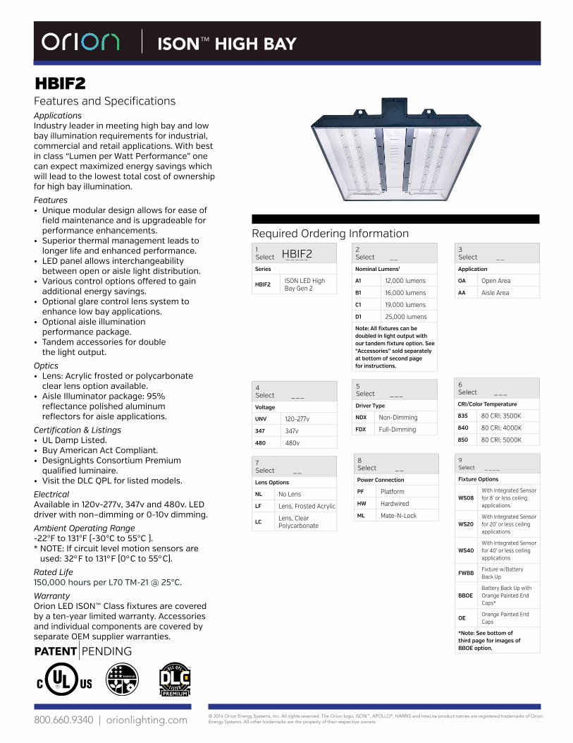
Features and SpecificationsApplications Industry leader in meeting high bay and low bay illumination requirements for industrial, commercial and retail applications. With best in class “Lumen per Watt Performance” one can expect maximized energy savings which will lead to the lowest total cost of ownership for high bay illumination.
Features• Unique modular design allows for ease of
field maintenance and is upgradeable forperformance enhancements.
• Superior thermal management leads tolonger life and enhanced performance.
• LED panel allows interchangeabilitybetween open or aisle light distribution.
• Various control options offered to gainadditional energy savings.
• Optional glare control lens system toenhance low bay applications.
• Optional aisle illuminationperformance package.
• Tandem accessories for doublethe light output.
Optics• Lens: Acrylic frosted or polycarbonate
clear lens option available.• Aisle Illuminator package: 95%
reflectance polished aluminumreflectors for aisle applications.
Certification & Listings• UL Damp Listed.• Buy American Act Compliant.• DesignLights Consortium Premium
qualified luminaire.• Visit the DLC QPL for listed models.
ElectricalAvailable in 120v-277v, 347v and 480v. LED driver with non–dimming or 0-10v dimming.
Ambient Operating Range-22°F to 131°F (-30°C to 55°C ).* NOTE: If circuit level motion sensors are
used: 32°F to 131°F (0°C to 55°C).
Rated Life150,000 hours per L70 TM-21 @ 25°C.
WarrantyOrion LED ISON™ Class fixtures are coveredby a ten-year limited warranty. Accessoriesand individual components are covered byseparate OEM supplier warranties.
Required Ordering Information1Select _____
Series
HBIF2 ISON LED High Bay Gen 2
5Select ___
Driver Type
NDX Non-Dimming
FDX Full-Dimming
3Select __
Application
OA Open Area
AA Aisle Area
6 Select ___
CRI/Color Temperature
835 80 CRI; 3500K
840 80 CRI; 4000K
850 80 CRI; 5000K
2Select __
Nominal Lumens1
A1 12,000 lumens
B1 16,000 lumens
C1 19,000 lumens
D1 25,000 lumens
Note: All fixtures can be doubled in light output with our tandem fixture option. See “Accessories” sold separately at bottom of second page for instructions.
4Select ___
Voltage
UNV 120-277v
347 347v
480 480v
8 Select __
Power Connection
PF Platform
HW Hardwired
ML Mate-N-Lock
HBIF2
7 Select __
Lens Options
NL No Lens
LF Lens, Frosted Acrylic
LC Lens, Clear Polycarbonate
9 Select ____
Fixture Options
WS08With Integrated Sensor for 8’ or less ceiling applications
WS20With Integrated Sensor for 20’ or less ceiling applications
WS40With Integrated Sensor for 40’ or less ceiling applications
FWBBFixture w/Battery Back Up
BBOEBattery Back Up with Orange Painted End Caps*
OEOrange Painted End Caps
*Note: See bottom of third page for images of BBOE option.
© 2016 Orion Energy Systems, Inc. All rights reserved. The Orion logo, ISON™, APOLLO®, HARRIS and InteLite product names are registered trademarks of Orion Energy Systems. All other trademarks are the property of their respective owners. 800.660.9340 | orionlighting.com
ISON™ HIGH BAY
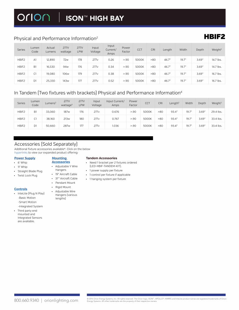
HBIF2Physical and Performance Information2
SeriesLumen Code
Actual Lumens
277V wattage
277V LPW
Input Voltage
Input Current/
Amps
Power Factor
CCT CRI Length Width Depth Weight3
HBIF2 A1 12,890 72w 178 277v 0.26 >.90 5000K >80 46.7” 19.7” 3.69” 14.7 lbs.
HBIF2 B1 16,530 94w 176 277v 0.34 >.90 5000K >80 46.7” 19.7” 3.69” 14.7 lbs.
HBIF2 C1 19,080 106w 179 277v 0.38 >.90 5000K >80 46.7” 19.7” 3.69” 16.7 lbs.
HBIF2 D1 25,330 143w 177 277v 0.52 >.90 5000K >80 46.7” 19.7” 3.69” 16.7 lbs.
Accessories (Sold Separately)Additional fixture accessories available*. Click on the below hyperlinks to view our expanded product offering:
Power Supply• 6’ Whip
• 11’ Whip
• Straight Blade Plug
• Twist Lock Plug
Mounting Accessories• Adjustable Y Wire
Hangers
• 19” Aircraft Cable
• 31’” Aircraft Cable
• Pendant Mount
• Rigid Mount
• Adjustable Wire Hangers (various lengths)
Controls• InteLite (Plug N Play)
-Basic Motion
-Smart Motion
-Integrated System
• Third party end mounted and Integrated Sensors are available.
Tandem Accessories• Need 1 bracket per 2 fixtures ordered
(LED-HBIF-TANDEM-KIT).
• 1 power supply per fixture
• 1 control per fixture if applicable
• 1 hanging system per fixture
In Tandem (Two fixtures with brackets) Physical and Performance Information4
SeriesLumen Code
Lumens5277V
wattage5
277V LPW
Input Voltage
Input Current/Amps
Power Factor
CCT CRI Length5 Width Depth Weight3
HBIF2 B1 33,060 187w 176 277v 0.676 >.90 5000K >80 93.4” 19.7” 3.69” 29.4 lbs.
HBIF2 C1 38,160 213w 180 277v 0.767 >.90 5000K >80 93.4” 19.7” 3.69” 33.4 lbs.
HBIF2 D1 50,660 287w 177 277v 1.036 >.90 5000K >80 93.4” 19.7” 3.69” 33.4 lbs.

© 2016 Orion Energy Systems, Inc. All rights reserved. The Orion logo, ISON™, APOLLO®, HARRIS and InteLite product names are registered trademarks of Orion Energy Systems. All other trademarks are the property of their respective owners. 800.660.9340 | orionlighting.com
ISON™ HIGH BAY
HBIF2
Rev. 160128
Additional Performance Information for a fixture
Fixture Options – Factory Installed
5K D1 OA 5K D1 AA
BBOE: Battery back up (test button shown) with orange painted end cap.
LF: Lens, frosted acrylic. LC: Lens, clear polycarbonate.
WS: With Integrated Sensor.
OE: Orange painted end caps.
Fixture Accessories – Field Installed
Additional Specification Information1 For actual lumens, see performance table2 Actual performance may vary by up to ±10% of values listed; facility factors and fixture options can affect performance values. Values, test results, and performance tables is based on an open area application at 277v3 Weight will vary based on option selection4 No electrical connection between fixtures; separate power supply cord used per fixture5 Information is result of 2 combined fixtures
Tandem bracket closeup for two fixtures.

© 2016 Orion Energy Systems, Inc. All rights reserved. The Orion logo, ISON™, APOLLO®, HARRIS and InteLite product names are registered trademarks of Orion Energy Systems. All other trademarks are the property of their respective owners. 800.660.9340 | orionlighting.com
APOLLO® HIGH BAY
HBAC2Features and Specifications
Applications Apollo HBAC2 is well suited to exceed high and low bay illumination requirements for industrial, commercial, and retail applications. Ideal when seeking feature rich, value oriented energy savings and maintenance reductions solution.
Features• Unique modular design allows for ease of
field maintenance and is upgradeable forperformance enhancements.
• Superior thermal management leads tolonger life and enhanced performance.
• Various control options offered toachieve additional energy savings.
• Optional glare control lens system toenhance low bay applications.
• Optional aisle illuminationperformance package.
• Aluminum powdered coated bodyfor thermal management.
• Tandem accessories for double the lightoutput.
OpticsLens: Acrylic frosted or polycarbonate clear.Aisle Illuminator package: 95% reflectance polished aluminum.
Certification & Listings• UL Damp Listed.• Buy American Act Compliant.• DesignLights Consortium Premium
qualified luminaire. • Visit the DLC QPL for listed models.
ElectricalAvailable in 120v-277v, 347v and 480v. LED driver with non–dimming or 0-10v dimming.
Ambient Operating Range-22°F to 131°F (-30°C to 55°C ).-4°F to 131°F (-20°C to 55°C) B2 versions only.* NOTE: If circuit level motion sensors are
used: 32°F to 131°F (0°C to 55°C ).
Rated Life125,000 hours per L70 TM-21 @ 25°C.
WarrantyOrion LED fixtures are covered by a five-year limited warranty. Accessories and individual components are covered by separate OEM supplier warranties.
Required Ordering Information1Select _____
Series
HBAC2APOLLO LED High Bay Gen 2
5Select ___
Driver Type
NDX Non-Dimming
FDX Full-Dimming
3Select __
Application
OA Open Area
AA Aisle Area
6 Select ___
CRI/Color Temperature
840 80 CRI; 4000K
850 80 CRI; 5000K
2Select __
Nominal Lumens1
A1 13,000 lumens
B1 15,000 lumens
B2 18,000 lumens
C1 21,000 lumens
D1 27,000 lumens
Note: All fixtures can be doubled in light output with our tandem fixture option. See “Accessories” sold separately at bottom of second page for instructions.
4Select ___
Voltage
UNV 120-277v
347 347v
480 480v
8 Select __
Power Connection
PF Platform
HW Hardwired
ML Mate-N-Lock
HBAC2
9 Select ____
Fixture Options
FWBBFixture w/Battery Back Up
WS08With Integrated Sensor for 8’ or less ceiling applications
WS20With Integrated Sensor for 20’ or less ceiling applications
WS40With Integrated Sensor for 40’ or less ceiling applications
BBOEBattery Back Up with Orange Painted End Caps*
OEOrange Painted End Caps
*Note: See third page for images of BBOE option.
7 Select __
Lens Options
NL No Lens
LF Lens, Frosted Acrylic
LCLens, Clear Polycarbonate

© 2016 Orion Energy Systems, Inc. All rights reserved. The Orion logo, ISON™, APOLLO®, HARRIS and InteLite product names are registered trademarks of Orion Energy Systems. All other trademarks are the property of their respective owners. 800.660.9340 | orionlighting.com
SeriesLumen Code
Actual Lumens
277V wattage
277V LPW
Input Voltage
Input Current/
Amps
Power Factor
CCT CRI Length Width Depth Weight3
HBAC2 A1 13,860 97w 143 277v 0.35 >.90 5000K >80 48.09” 16.9” 2.9” 11 lbs.
HBAC2 B1 14,910 106w 141 277v 0.38 >.90 5000K >80 48.09” 16.9” 2.9” 13 lbs.
HBAC2 B2 17,890 118w 151 277v 0.42 >.90 5000K >80 48.09” 16.9” 2.9” 13 lbs.
HBAC2 C1 21,520 142w 152 277v 0.51 >.90 5000K >80 48.09” 16.9” 2.9” 13 lbs.
HBAC2 D1 27,200 194w 140 277v 0.70 >.90 5000K >80 48.09” 16.9” 2.9” 13 lbs.
APOLLO® HIGH BAY
HBAC2
Accessories (Sold Separately)Additional fixture accessories available*. Click on the below hyperlinks to view our expanded product offering:
Power Supply• 6’ Whip
• 11’ Whip
• Straight Blade Plug
• Twist Lock Plug
Mounting Accessories• Adjustable Y Wire
Hangers
• 19” Aircraft Cable
• 31’” Aircraft Cable
• Pendant Mount
• Rigid Mount
• Adjustable Wire Hangers (various lengths)
Controls• InteLite (Plug N Play)
-Basic Motion
-Smart Motion
-Integrated System
• Third party end mounted and Integrated Sensors are available.
Tandem Accessories• Need 1 bracket per 2 fixtures ordered
(LED-HBAC-TANDEM-KIT).
• 1 power supply per fixture
• 1 control per fixture if applicable
• 1 hanging system per fixture
In Tandem (Two fixtures with brackets) Physical and Performance Information4
SeriesLumen Code
Lumens5277V
wattage5
277V LPW
Input Voltage
Input Current/Amps
Power Factor
CCT CRI Length5 Width Depth Weight3
HBAC2 B1 29,820 212w 141 277v 0.765 >.90 5000K >80 96.18” 16.9” 2.9” 26 lbs.
HBAC2 B2 35,780 237w 151 277v 0.854 >.90 5000K >80 96.18” 16.9” 2.9” 26 lbs.
HBAC2 C1 43,040 283w 152 277v 1.022 >.90 5000K >80 96.18” 16.9” 2.9” 26 lbs.
HBAC2 D1 54,400 388w 140 277v 1.402 >.90 5000K >80 96.18” 16.9” 2.9” 26 lbs.
Physical and Performance Information2

© 2016 Orion Energy Systems, Inc. All rights reserved. The Orion logo, ISON™, APOLLO®, HARRIS and InteLite product names are registered trademarks of Orion Energy Systems. All other trademarks are the property of their respective owners. 800.660.9340 | orionlighting.com
Additional Performance Information for a fixture
5K D1 AA5K D1 OA
Additional Specification Information1For actual lumens, see performance table. 2Actual performance may vary by up to ±10% of values listed; facility factors and fixture options can affect performance values. Values, test results, and performance tables is based on an open area application at 277v. 3Weight will vary based on option selection.4No electrical connection between fixtures; separate power supply cord used per fixture.5Information is result of 2 combined fixtures.
Fixture Accessories – Field Installed
HBAC2
APOLLO® HIGH BAY
Rev. 160119
Tandem bracket closeup for two fixtures.
Fixture Options – Factory Installed
BBOE: Battery back up (test button shown) with orange painted end cap.
LC: Lens, clear polycarbonate.LF: Lens, frosted acrylic.
WS: With Integrated Sensor.
OE: Orange painted end caps.

© 2016 Orion Energy Systems, Inc. All rights reserved. The Orion logo, ISON™, APOLLO®, HARRIS and InteLite product names are registered trademarks of Orion Energy Systems. All other trademarks are the property of their respective owners. 800.660.9340 | orionlighting.com
HARRIS HIGH BAY
HBHC1Features and SpecificationsApplications Harris HBHC1 is well suited to meet high and low bay illumination requirements for industrial, commercial, and retail applications. Ideal when seeking a cost effective solution that will drive energy savings and maintenance reductions over traditional HID and linear fluorescent high and low bay lighting systems.
Features• Modular power pack is field replaceable
for ease of fixture maintenance.• Various control options offered to
achieve additional energy savings.• Optional aisle illumination
performance package.• Aluminum powder coated body
for thermal management.• Tandem accessories for
double the light output.
OpticsAisle Illuminator package: 95% reflectance polished aluminum.
Certification & Listings• UL Damp Listed. • Buy American Act Compliant. • DesignLights Consortium Premium
qualified luminaire.• Visit the DLC QPL for listed models.
ElectricalAvailable in 120v-277v, 347v and 480v. LED driver with non–dimming or 0-10v dimming.
Ambient Operating Range-4°F to 122°F (-20°C to 50°C ) * NOTE: If circuit level motion sensors
are used: 32F to 122°F (0°C to 50°C )
Rated Life100,000 hours L70 TM-21 @ 25°C.
WarrantyOrion LED fixtures are covered by a five-year limited warranty. Accessories and individual components are covered by separate OEM supplier warranties.
Required Ordering Information
1Select _____
Series
HBHC1 Harris LED High Bay Gen 1
5Select ___
Driver Type
NDX Non-Dimming
FDX Full-Dimming
3Select __
Application
OA Open Area
AA Aisle Area
6 Select ___
CRI/Color Temperature
840 80 CRI; 4000K
850 80 CRI; 5000K
2Select __
Nominal Lumens1
A1 11,000 lumens
A2 15,000 lumens
B1 19,000 lumens
C1 22,000 lumens
Note: All fixtures can be doubled in light output with our tandem fixture option. See “Accessories” sold separately at bottom of second page for instructions.
4Select ___
Voltage
UNV 120-277v
347 347v
480 480v
7 Select __
Power Connection
PF Platform
HW Hardwired
ML Mate-N-Lock
HBHC1

© 2016 Orion Energy Systems, Inc. All rights reserved. The Orion logo, ISON™, APOLLO®, HARRIS and InteLite product names are registered trademarks of Orion Energy Systems. All other trademarks are the property of their respective owners. 800.660.9340 | orionlighting.com
HARRIS HIGH BAY
HBHC1
Rev. 160318
Accessories (Sold Separately)Additional fixture accessories available*. Click on the below hyperlinks to view our expanded product offering:
Power Supply• 6’ Whip
• 11’ Whip
• Straight Blade Plug
• Twist Lock Plug
Mounting Accessories• Adjustable Y Wire
Hangers
• 19” Aircraft Cable
• 31’” Aircraft Cable
• Pendant Mount
• Rigid Mount
• Adjustable Wire Hangers (various lengths)
Controls• InteLite (Plug N Play)
-Basic Motion
-Smart Motion
-Integrated System
• Third party end mounted sensor are available.
Additional Specification Information1 For actual lumens, see performance table. 2 Actual performance may vary by up to ±10% of values listed; facility factors and fixture options can affect performance values. Values, test results, and performance tables is based on an open area application at 277v. 3 Weight will vary based on option selection.4 No electrical connection between fixtures; separate power supply cord used per fixture.5 Information is result of 2 combined fixtures.6 Tandem bracket requires field installation.
In Tandem (Two fixtures with brackets) Physical and Performance Information4
SeriesLumen Code
Lumens5277V
wattage5
277V LPW
Input Voltage
Input Current/Amps
Power Factor
CCT CRI Length5 Width Depth Weight3
HBHC1 A2 29,560 210 140 277v .792 >.90 5000K >80 96.1” 11.7” 2.86” 10 lbs.
HBHC1 B1 39,740 266w 149 277v .96 >.90 5000K >80 96.18” 11.7” 2.86” 13.2 lbs.
HBHC1 C1 45,100 323w 140 277v 1.164 >.90 5000K >80 96.18” 11.7” 2.86” 13.2 lbs.
Additional Performance Information for a fixture
5K C1 OA 5K C1 AA
Tandem bracket closeup for two fixtures.
Tandem Accessories• Need 1 bracket per 2 fixtures ordered
(LED-HBHC1-TANDEM-KIT).
• 1 power supply per fixture needed.
• 1 hanging system per fixture needed.
• 1 control per fixture (if applicable).
Physical and Performance Information2
SeriesLumen Code
Actual Lumens
277V wattage
277V LPW
Input Voltage
Input Current/
Amps
Power Factor
CCT CRI Length Width Depth Weight3
HBHC1 A1 11,350 82w 139 277v .30 >.90 5000K >80 48.09” 11.7” 2.86” 4.6 lbs.
HBHC1 A2 14,780 105w 140 277v .396 >.90 5000K >80 48.09” 11.7” 2.86” 5 lbs.
HBHC1 B1 19,870 133w 149 277v .48 >.90 5000K >80 48.09” 11.7” 2.86” 6.6 lbs.
HBHC1 C1 22,550 161w 140 277v .58 >.90 5000K >80 48.09” 11.7” 2.86” 6.6 lbs.
10/02/2012 08 62 70 - 1 Tubular Skylights
© 2011 - Orion Energy Systems, Inc.
SECTION 08 62 70 (08622)
TUBULAR SKYLIGHTS
(PERFORMANCE-BASED)
PART 1 GENERAL
1.1 SUMMARY
A. Section Includes:1. Tubular skylight system consisting of collector dome, roof flashing unit, light pipe,
and diffuser assembly.
B. Related Sections:1. Applicable provisions of Division 01 shall govern all work under this Section.
1.2 REFERENCES
A. American Architectural Manufacturers Association (AAMA):1. AAMA/WDMA/CSA 101/I.S. 2/A440 - Specification for Windows, Doors and Unit
Skylights.
B. American National Standards Institute (ANSI):1. ANSI Z97.1 – Safety Glazing Materials Used in Buildings - Safety Performance
Specifications and Methods of Test.
C. ASTM International:1. ASTM B209 - Standard Specification for Aluminum and Aluminum-Alloy Sheet and
Plate.2. ASTM B221 - Standard Specification for Aluminum and Aluminum-Alloy Extruded
Bars, Rods, Wire, Profiles, and Tubes.3. ASTM D4586 – Standard Specification for Asphalt Roof Cement, Asbestos-Free.4. ASTM D256 – Standard Test Methods for Determining the Izod Pendulum Impact
Resistance of Plastics.5. ASTM D542 – Standard Test Method for Index of Refraction of Transparent Organic
Plastics.6. ASTM D635 – Standard Test Method for Rate of Burning and/or Extent and Time of
Burning of Plastics in a Horizontal Position.7. ASTM D638 – Standard Test Method for Tensile Properties of Plastics.8. ASTM D695 – Standard Test Method for Compressive Properties of Rigid Plastics.9. ASTM D696 – Standard Test Method for Coefficient of Linear Thermal Expansion
of Plastics between -30 Degrees C and 30 Degrees C with a Vitreous SilicaDilatometer.

10/02/2012 08 62 70 - 2 Tubular Skylights
© 2011 - Orion Energy Systems, Inc.
10. ASTM D785 – Standard Test Method for Rockwell Hardness of Plastics and Electrical Insulating Materials.
11. ASTM D790 – Standard Test Methods for Flexural Properties of Unreinforced and Reinforced Plastics and Electrical Insulating Materials.
12. ASTM D792 – Standard Test Methods for Density and Specific Gravity (Relative Density) of Plastics by Displacement.
13. ASTM D1003 – Standard Test Method for Haze and Luminous Transmittance of Transparent Plastics.
14. ASTM D1929 – Standard Test Method for Determining Ignition Temperature of Plastics.
15. ASTM D2583 - Standard Test Method for Indentation Hardness of Rigid Plastics by Means of a Barcol Impressor.
16. ASTM D4802 - Standard Specification for Poly (Methyl Methacrylate) Acrylic Plastic Sheet.
17. ASTM E84 – Standard Test Method for surface burning characteristics of building materials.
D. Florida Building Code: 1. TAS 201-94 Impact Test Procedures as required by section 1626 Florida Building
Code. 2. TAS 202-94 Test Impact and Non Impact Resistant Building Envelope components
using uniform static air pressure as required by section 1626 Florida Building Code. 3. TAS 2-3-94 Cyclic Wind Pressure Procedure as required by section 1626 Florida
Building Code.
E. National Fenestration Rating Council 1. NFRC 102-2010 Thermal Performance Test
1.3 SUBMITTALS
A. Product Data: Submit product data for tubular skylight specified.
B. Shop Drawings: Provide shop drawings indicating sections, details and connections to roof and other adjoining work to ensure structural integrity and interference avoidance with other building systems as required.
C. Samples for Verification: Submit samples if requested by Owner.
D. Submit copies of sample warranties.
1.4 QUALITY REQUIREMENTS
A. Manufacturer Qualifications: Manufacturer capable of fabricating tubular skylight systems that meet or exceed performance requirements as indicated.
B. Installer Qualifications: Certified roofing contractor for roofing system in place trained by manufacturer in installation of specified tubular skylights.

10/02/2012 08 62 70 - 3 Tubular Skylights
© 2011 - Orion Energy Systems, Inc.
1.5 WARRANTY
A. Manufacturer's standard form in which manufacturer agrees to repair or replace any tubular skylight that fails in materials or workmanship within ten years of date of installation.
PART 2 PRODUCTS
2.1 TUBULAR SKYLIGHT FABRICATION
A. Dimensions: Standard Unit 1. Internal Diameter: 22.25 inches. 2. Length below Bottom of Flashing Unit: 7.75 inches.
B. Upper Collection Dome: 1. Colorless dome shall have visible light transmission rating of no less than 92 percent. 2. Fabricate Acrylic dome from 0.160-inch thick colorless, optical grade material with
crystal clear forming capabilities. 3. Fabricate Polycarbonate dome from 0.236-inch thick colorless, optical grade material
with crystal clear forming capabilities. 4. Material shall have the following properties:
ASTM Test Typical Value Typical Value
Property Method Acrylic Polycarbonate Specific Gravity D792 1.19 1.20 Tensile Strength D638 11,300 psi 9,500 psi Elongation, Rupture 4 - 6 percent 110 percent Modulus of Elasticity 470,000 psi 340,000 psi Flexural Strength D790 16,200 psi 13,500 psi Modulus of Elasticity 500,000 psi 345,000 psi Impact Strength D256 0.36 ft.lbs/inch of notch 18. ft.lbs/inch of notch Izod Milled Notch Rockwell Hardness D785 M-95 -- Refractive Index D542 1.49 1.586 Yellowness Index D1925 <1 percent -- Haze D1003 <1 percent -- Light Transmission, Total D1003 92 percent 86 percent Maximum Recommended Continuous Service Temperature 160 degrees F -- Coefficient of Linear D696 0.000040 in/in – degree F 0.0000375 in/in – degree F Thermal Expansion Flammability, Burning Rate D635 CC2 CC1 (0.060” – 0.25”) Self Ignition Temperature D1929 850 degrees F 1022 degrees F
5. Dome shall securely attach to flashing in a manner fully supporting dome with no stress concentrations in dome or fastening system.
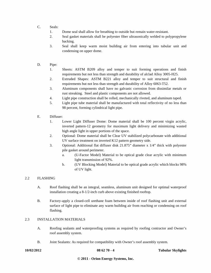
10/02/2012 08 62 70 - 4 Tubular Skylights
© 2011 - Orion Energy Systems, Inc.
C. Seals: 1. Dome seal shall allow for breathing to outside but remain water-resistant. 2. Seal gasket materials shall be polyester fiber ultrasonically welded to polypropylene
backing. 3. Seal shall keep warm moist building air from entering into tubular unit and
condensing on upper dome.
D. Pipe: 1. Sheets: ASTM B209 alloy and temper to suit forming operations and finish
requirements but not less than strength and durability of alclad Alloy 3005-H25. 2. Extruded Shapes: ASTM B221 alloy and temper to suit structural and finish
requirements but not less than strength and durability of Alloy 6063-T52. 3. Aluminum components shall have no galvanic corrosion from dissimilar metals or
rust streaking. Steel and plastic components are not allowed. 4. Light pipe construction shall be rolled, mechanically riveted, and aluminum taped. 5. Light pipe tube material shall be manufactured with total reflectivity of no less than
98 percent, forming cylindrical light pipe.
E. Diffuser: 1. Lower Light Diffuser Dome: Dome material shall be 100 percent virgin acrylic,
inverted pattern-12 geometry for maximum light delivery and minimizing wasted high angle light in upper portions of the space.
2. Optional: Dome material shall be Clear UV stabilized polycarbonate with additional UV surface treatment on inverted K12 pattern geometry side.
3. Optional: Additional flat diffuser disk 21.875” diameter x 1/4” thick with polyester pile gasket around perimeter. a. (U-Factor Model) Material to be optical grade clear acrylic with minimum
light transmission of 92%. b. (UV Blocking Model) Material to be optical grade acrylic which blocks 98%
of UV light.
2.2 FLASHING
A. Roof flashing shall be an integral, seamless, aluminum unit designed for optimal waterproof installation creating a 8-1/2-inch curb above existing finished rooftop.
B. Factory-apply a closed-cell urethane foam between inside of roof flashing unit and external surface of light pipe to eliminate any warm building air from reaching or condensing on roof flashing.
2.3 INSTALLATION MATERIALS
A. Roofing sealants and waterproofing systems as required by roofing contractor and Owner’s roof assembly system.
B. Joint Sealants: As required for compatibility with Owner’s roof assembly system.

10/02/2012 08 62 70 - 5 Tubular Skylights
© 2011 - Orion Energy Systems, Inc.
C. Mastic Sealant: Polyisobutylene; nonhardening, nonskinning, nondrying, nonmigrating sealant.
D. Roofing Cement: ASTM D4586, asbestos free, designed for trowel application or other adhesive compatible with roofing system.
2.4 PERFORMANCE
A. Contractor to install tubular skylights in accordance with all applicable federal, state, and local codes, laws, and regulations affecting the Work, including, but not limited to, occupational health, safety, welfare, accident prevention, safety equipment, and roofing system warranty requirements.
B. Tubular skylights must be 100 percent factory assembled and delivered to project ready to install with no additional assembly required. Factory controlled geometry; processes, and environment shall assure consistent and superior quality over field assembled units.
C. Fully assembled tubular skylights shall meet or exceed the following requirements when tested in accordance with AAMA/WDMA/CSA 101/I.S. 2/A440: 1. Air Infiltration Test: Air infiltration will not exceed 0.10 cfm/sq.ft. across aperture
with a chamber pressure of +01.57 and -1.57 psf. 2. Water Penetration Test: No water shall flow over interior face during 4 five minute
cycles and 1 fifteen minute cycle with a chamber pressure of 10.65 psf. 3. Uniform Load Deflection Test: Deflection on unit shall be less than L/175 with a
chamber pressure of +70 and -70 psf. 4. Structural Load Test: Permanent set shall be less than 0.3 percent L with a chamber
pressure of +140 and -140 psf. 5. Florida State Wide Approval must meet or exceed the following requirements when
tested in accordance with TAS 201-94, TAS 202-94, TAS 203-94.
D. Additional 21.875” diameter x ¼” thick clear acrylic increases the units U-Factor per NFRC 102-2010 from 1.44 Btu/hr*ft2*F to 0.60 Btu/hr*ft2*F
PART 3 EXECUTION
3.1 EXAMINATION
A. Do not begin installation until all locations have been verified for appropriate placement. Take all necessary precautions and field verify that installed units will not interfere with roof top units, accessories, hatches, vents, stacks, access to equipment requiring maintenance, and the like.
B. Field verify that tubular skylights will not be blocked from direct sun light due to changes in roof height, firewalls, parapets, or equipment. If a potential conflict arises, resolve with Owner prior to installation.
C. Field verify, inside facility, that no obstructions are within roof structure or facility below unit

10/02/2012 08 62 70 - 6 Tubular Skylights
© 2011 - Orion Energy Systems, Inc.
location(s) including, but not limited to, structural members, gas lines, water or sewer pipes, suspended HVAC equipment, electrical distribution, owner process equipment, conveyors, or any other item that may interfere with safe and effective installation.
D. When installing an array of tubular skylights, take care to strike a consistent and square grid so units align cleanly in facility where possible. If an obstruction is encountered requiring an offset from array, consult with Owner to confirm alternate location(s) prior to proceeding with installation.
E. Do not begin installation until substrates have been properly prepared to acceptable conditions in accordance with roofing system manufacturer’s requirements.
3.2 INSTALLATION
A. Coordinate installation of tubular skylights with substrate, vapor retarder, roof insulation, roofing system, and flashing as required by roofing system manufacturer to ensure that each element of the Work performs properly and that combined elements are waterproof and weather tight.
B. Do not remove tubular skylight from shipping box until located on roof. No scratches or foreign materials are acceptable on collector dome and no dents or deformation of flashing or light pipe are allowed.
C. Disassembly of unit is not allowed in field. No additions or subtractions from unit are allowed. Do not paint or coat tubular skylight. Do not substitute fasteners installed on pre-assembled unit.
D. Tubular skylight seals shall be tested prior to shipment. If any seals are broken or damaged, entire unit must be replaced. No field repairs of any components are allowed except dome replacement. Instructions for dome replacement are shipped with replacement domes.
E. Removal and preparation of roof openings shall be in accordance with all safety requirements and best practices to eliminate any and all foreign materials, personnel or otherwise from falling into facility. In addition, secure off work areas within facility below all working areas as required.
F. Finished roof opening shall have a maximum diameter of 23 inches. Larger openings can expose cold roof or tubular skylight to warm moist air from inside building. WARNING: This cannot be allowed or condensation and heat gain/loss will occur in some installations. Installer will assure no condensation can occur and installer will be responsible for any damage caused by condensation due to improper installation.
G. Maintain roofing system, vapor retarder, insulation, and substrate integrity around entire opening. Dry fit tubular skylight into opening to allow for appropriate clearance around unit. Do not force unit into opening.

10/02/2012 08 62 70 - 7 Tubular Skylights
© 2011 - Orion Energy Systems, Inc.
H. Finish interior face and external and interior edges of roof opening for long-term stability and finish appearance in accordance with roofing manufacturer’s requirements.
I. Prepare roofing surface material thoroughly around opening to be free of any and all debris, moisture, or other adverse conditions prior to permanently placing unit into roof system. This includes removal of any metal debris or shavings created from making hole. Thoroughly vacuum up loose particles and debris around entire perimeter of opening a minimum of 24 inches beyond OD of roof-flashing flange.
J. Place three (3) concentric 3/8-inch beads of appropriate roofing sealant on underside of roof flashing mounting flange prior to installation. DO NOT SCRATCH OR DAMAGE COLLECTION DOME. PROTECT SURFACE FROM DAMAGE.
K. Fasten roof-flashing unit to roofing system with fasteners by Roofing Contractor in accordance with roof system requirements using pre-punched hole locations as a maximum fastener spacing for membrane or built-up roofing systems. Attachment to metal roof systems requires a 1.5 inch fastener spacing. Use round head fasteners to avoid sharp edges under waterproofing applied over flashing unit. Do not use any steel fasteners in exposed locations regardless of coating or treatment.
L. Do not attach unit to building structure. Tubular skylight shall move with roofing system for long-term seal integrity.
M. Apply waterproofing material over and around entire roof-flashing unit to form a seal similar to boot flashing used around cylindrical vent stacks. Roll waterproofing material up 5 inches onto vertical face of roof flashing unit and a minimum of 6 inches past horizontal flange on roof to create a continuous waterproof seal with the roofing system.
N. Engage a qualified testing agency to perform tests and inspections to ensure a waterproof installation has been achieved, if required by Owner.
O. Work will be considered defective if it does not pass specified tests and inspections.
P. Perform additional testing and inspections, at Contractor's expense, to determine compliance of replaced or additional work with specified requirements.
3.3 CLEAN-UP
A. Clean exposed dome surfaces using a soft damp cloth and water as required leaving a clean dome.
B. Remove all packaging, materials, and debris from rooftop to leave job site in a clean and professional manner.
C. Each installation shall be done in a consistent and professional manner. All tubular skylights shall be and look identical to each other after installation.

10/02/2012 08 62 70 - 8 Tubular Skylights
© 2011 - Orion Energy Systems, Inc.
END OF SECTION

© 2015 Orion Energy Systems, Inc. All rights reserved. The Orion logo, ISON™, APOLLO®, HARRIS and InteLite product names are registered trademarks of Orion Energy Systems. All other trademarks are the property of their respective owners. 800.660.9340 | orionlighting.com
APOLLO® LIGHT PIPE
LP
PATENT|PENDING
Features and SpecificationsApplications Daylighting device designed for commercial and industrial applications.
ConstructionIndustry first, factory installed closed cell insulation between roof flashing and light pipe minimizes conductive and convective thermal transfer from external components to interior of building for increased energy efficiency. Silicone seals the diffuser to the light pipe, keeping warm, moist, building air from entering the reflector tube and condensing on the upper dome. Solid clamping band.
Certification & Listing• Standard Apollo is AAMA/WDMA/
CSSA 101/I.S.2/A440-08 certified. • All domes meet or exceed
performance levels specified in 2006 IBC standards.
FinishSeamless, all-aluminum construction with built-in roof flashing and a solid clamping ring. Acrylic dome is standard.
WarrantyOrion Daylight Harvesting Light Pipes are covered by a one-year limited warranty. Accessories and individual components are covered by separate OEM supplier warranties.
Required Ordering Information1
Rev. 160107
Options (must be ordered separately)• Ambient light sensor integration
• Wire Guard for security and additional protection in gymnasiums
• Extension kit assemblies to accommodate various ceiling designs
• Interior trim ring and transition box (round to square) for applications such as drop ceilings
Series
Apollo Solar Light Pipe
Pipe Length
16.3” Pipe Length (fox maximum total roof system thickness of 7.0”)
24.3” Pipe Length (for maximum total roof system thickness of 15.0”)
32.8” Pipe Length (for maximum total roof system thickness of 23.0”)
49.2” Pipe Length (for maximum total roof system thickness of 39.0”)
Diffuser
Single Diffuser
Double Diffuser with standard acrylic disk
Double Diffuser with 99% UV blocking acrylic disk
Diameter
22.25” Light Pipe Diameter
Additional Specification Information1 Contact your Orion representative when placing your order.
Made in USA

1.800.660.9340 | +1 920.482.0520
orionlighting.com
P-INT-XS-028 170424