architectural acoustics and the arts - bbcdownloads.bbc.co.uk/rd/pubs/reports/1963-24.pdf ·...
TRANSCRIPT

RESEARCH DEPARTMENT
Architectural acoustics and the arts
REPORT No. 8·077 1963/24
-------- ;.
THE BRITISH BROADCASTING CORPORATION
ENGINEERING DIVISION

RESEARCH DEPARTMENT
ARCHITECTURAL ACOUSTICS AND THE ARTS
Report No. B-077
0963/24)
To Somervi11 e, B.Sc., M.LE.E., F.lnst.P. (T .. Somerville)
This Report is the property of the British Broadcasting Corporation and may Dot be reproduced in any form without the written permission of the Corporation.
4 I

Section
l.
2.
3.
4.
5.
6.
7.
8.
9.
10.
11.
12.
13.
14.
15.
Report No. B-077
ARCHITECTURAL ACOUSTICS AND THE ARTS
INTRODUCTION
REVERBERATION
DIFFUSION
ACOUSTICS IN ANCIENT TIMES
ACOUSTICS OF CHURCHES
OPERA HOUSES
THEATRES ..
CONCERT HALLS
Title
ACOUSTIC TREATMENT TO CONTROL REVERBERATION
ACOUSTICS OF SMALL ROOMS
LECTURE THEATRES . .
SOUND REINFORCEMENT
AMBI OPHONY .
NOISE AND SOUND INSULATION
REFERENCES . . . . . . . .
Page
1
2
3
3
4
5
5
5
7
8
9
9
11
11
13

June 1963 Report No. B-077
(1963/24)
ARCHITECTURAL ACOUSTTCS AND THE ARTS
An article published in the Tnstitute of Physics and Physical Society Bulletin, May 1963, based on a lecture given on 10th December 1962 to their Manchester area branch.
1. INTRODUCTION
An invitation to lecture on acoustics leads to difficulties in the selection of material from a subject which covers a very wide field. Acoustics is not, as many people imagine, exactly equivalent to what is usually termed 'sound' in university curricula. The subject is in fact much more extensive and has been rather neglected by universities in this country for many years. It is gratifying however to notice signs that universities are aware of the deficiency and courses in various aspects of acoustics are now available. It must not be assumed however that physics departments are the only departments involved in this subject, since many of the courses are provided by electrical engineering departments because of the connections with telecOllllluni cations.
The subject now covers the following fields:
(a) Speech and hearing, whi ch includes medical applications such as audiometry.
(b) Architectural problems of sound insulation and the adjustment of reverberation in enclosures.
(c) Vibration problems in buildings and ln machinery.
(d) Noise in all its forms.
(e) Ultrasonics used in various industrial processes - for example, for flaw detection and cleaning, and in medical applications (e.g. for diagnosing brain tumours).
The array of material is so extensive that it will be necessary to restrict this article and the choice has fallen on architectural acoustics. This covers the various types of enclosures for audiences such as lecture theatres, concert halls and also broadcasting studios and it will be necessary to consider the aesthetic aspects of the problem. In these types of enclosure problems of sound insulation and vibration also arise and will be mentioned.
2
2. REVERBERATION
In all enclosures the most important acoustic characteristic is the way in which sound builds up and decays. The building up of sound energy in an enclosed space is determined by the reflecting and absorbing properties of the various surfaces. In rooms with highly reflecting surfaces sound builds up to higher intensities and takes longer to decay than in rooms with absorbent surfaces. The building up of sound is known as reverberation and the time taken for the sound to decay after the source ceases is the reverberation time. The first investigation of this phenomenon was carried out many years ago by w.e. Sabine1 who was the first to establish that the multiple reflections throughout a room could be reduced by absorbing surfaces consisting of porous materials; it was as a result of his experiments that he postulated the theory of reverberation.
Sabine defined the reverberation time as the time taken for the sound to die away to inaudibility, but as this is not a very exact definition it is now defined as the time taken for the sound intensity to decrease by 60 decibels after being stopped, which is a ratio of a million to one. Sabine employed organ pipes to produce the sound and measured the time of decay by a chronograph; experiments were carried out in a lecture theatre at Harvard University in which the reverberation was so great that lecturing was almost impossible. He used cushions as the absorbing material and although his timing apparatus was extremely rudimentary he was able to show how the theatre could be corrected. Sabine subsequently carried out many other investigations as a consultant in acoustics. His best known example of acoustic design IS
the Symphony Hall in Boston, Massachusetts, which has an excellent reputation.
After Sabine's time there was unfortunately little investigation of acoustic phenomena until the early twenties, when microphones became available and were used to pick up sound in broadcasting, recording and talking picture studios. It was soon discovered that a single microphone gave results much more reverberant than would be expected when listening in the studio. It was realised that normal hearing, which is binaural, helps to reduce the effects of reverberation and that a single microphone, which is equivalent to a single ear, has the opposite effect. It has therefore been customary to reduce the reverberation time of broadcasting and recording studios below that normally required for an audience.
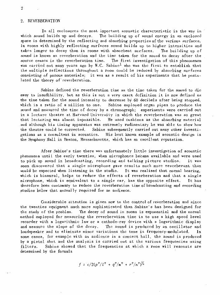
Considerable attention is given now to the control of reverberation and since the twenties equipment much more sophisticated than Sabine's has been designed for the study of the problem. The decay of sound in rooms is exponential and the normal method employed for measuring the reverberation time is to use a high speed level recorder with a logarithmic law or a cathode-ray device with a logarithmic display and measure the slope of the decay. The sound is produced by an oscillator and loudspeaker and to eliminate minor variations the tone is frequency-modulated. In some cases,for example with an audience in a concert hall, the sound is produced by a pistol shot and the analysis is carried out at the various frequencies using filters. Sabine showed that the frequencies at which a room will resonate are determined by the formula

3
Where f 1S the frequency of the nonnal mode
c is the velocity of sound
l, m and n are the dimensions of the enclosure
p, q and r are whole numbers.
The lowest frequency is determined by the longest dimension, and the next lowest by the other principal dimensions of the enclosure, which are usually the width and the height. These three frequencies, which are known as the axial modes, are accompanied by a series of hannonics. In addition, there is a complicated series of resonances due to multiple reflections and these also can be obtained from the fonnula. In any enclosure the fundamental resonances and the earlier harmonics in the series are reasonably spaced but as the frequencies increase the pattern becomes extremely complicated. In small rooms the axial modes fall in the low frequency regions in speech and when excited produce objectionable colourations, while in large enclosures such as concert halls the axial modes are very low in frequency and are not troublesome in speech or music.
As reverberation has been studied for many years there is now fairly general agreement on the optimum reverberation times required for various types of enclosure. If the reverberation time is too short, the sound lacks warmth, while if it is too long speech intelligibility is poor, and music is confused.
3. DIFFUSION
It was soon realised in broadcasting that even if the reverberation times of studios were adjusted to the most acceptable value studios could still give a poor perfonnance. This had also been found out in the case of concert halls, many of which fulfilled the requirements regarding reverberation and yet were thoroughly bad. In the last twenty-five years much work has been done, particularly on the subject of diffusion. By diffusion we mean the scattering of sound throughout r
an enclosure in such a manner that the sound energy is distributed evenly in all directions. It was realised that many of the good concert halls had elaborate' ornamentation, often in the form of coffering, and it was suspected that this was closely connected with the good acoustics. ~;lany experiments were conducted by broadcasting organisations which showed that much improvement could be achieved by diffusing sound in studios by means of wall and ceiling irregularities. Many configurations were tried, and hemicylindrical and triangular formations became popular in the United States and in some Continental countries. However, experiments carried out by the BBC2 clearly showed that rectangular formations were better and they have consequently been favoured in this country for broadcasting studios.
Although much work has been done on diffusion, which is such an important feature, it has proved very difficult to measure with any accuracy the state of diffusion.
4. ACOUSTICS IN ANCIENT TIMES
Some of the earliest recorded examples of theatres were in Greece. These were of course open air theatres and in many parts of the Mediterranean area there are examples of Roman theatres, some of which are in a fairly good state of preser-
4
vation. These theatres were semi-circular in plan, the stage area being situated along the diameter while the audience was seated in steeply-raked galleries. It is obvious that such a theatre must have a reverberation time which is very short because the sound which reaches the audience is mainly absorbed and the remainder disappears upwards into the open air. Consequently there is no doubt that in such theatres there is no difficulty with confusion due to reverberation and that it is possible to hear clearly the speech from the stage. The distances however are great since the diameter of the circle is of the order of 300 to 400 ft (92 m to 122 m). It would therefore seem that loud voices would be an asset.
To overcome the very short reverberation time the Greeks are reported to have installed, under the seats, what we now call Helmholtz resonators. These resonators were shaped like bottles and were apparently of different sizes so as to reinforce different frequency regions. It should be mentioned that a Helmholtz resonator consists of a cavity in a rigid structure communicating with the open air by means of an aperture which can take the form of a neck of a bottle or a sli t. Resonance is due to the vibration of the mass of the air in the aperture, against the compliance of the air in the cavity. Helmholtz was an eminent German physicist who at a later date postulated the theory of this type of resonator.
5. ACOUSTICS OF CHURCHES
The commonest form of building used for assemblies is the church,. CllUrches were invariably constructed of hard reflecting materials such as stonework, timber or glass, and consequently there is little absorption, except that provided by the congregation. As a result the reverberation time is usually long and produces confusion which causes poor intelligibility in speech. The commonest way of overcoming this difficulty in older churches was to erect a sounding board over the preacher, but in the last decade electronic sound reinforcing systems have become common. It appears that the Scandinavians were aware of the trouble caused by exceSSlve reverberation and there is evidence that in some Scandinavian countries Helmholtz resonators were installed, not to increase the reverberation as in the Greek theatres, but to decrease it. The Helmholtz resonator can be made to absorb sound if resistance to the movement of the air is provided and this was apparently done in Scandinavia by putting ashes inside the resonator. The usual method in modern resonators is to apply a resistance in the aperture by using some porous material such as fabric or fine wire mesh.
It is not surprising that the style and composltlon of early traditional ecclesiastical music reflects the reverberant type of environment. Because of the long reverberation time music for performance in ecclesiastical surroundings tends to be slow in tempo and openly scored, otherwise the parts in the score become confused. For the same reason preachers must pitch their voices on one of the prominent resonances otherwise the intelligibility will be poor. Churches, of course, like other buildings, vary much in their acoustic performance. Some of them are very poor as regards intelligibility whereas some are excellent even though the reverberation time is long. The latter are usually found to have many irregularities in the interior of the building in the form of ornamentation which scatter the sound and produce good diffusion, so that a sound produced anywhere is well distributed throughout. An outstanding example of good ecclesiastical acoustics is King's College Chapel, Cambridge. The reader himself will be able to supply many bad exampl es.

5
6, OPERA HOUSES
A type of enclosure which is normally short in reverberation time is the opera houseo Because of the importance of the human voice in opera, it is necessary for the audience to be reasonably close to the stage and to ensure good diction the reverberation time must be short. Both these requirements are admirably satisfied by the Italian style of opera house, in which the audience is seated in stalls, and balconies arranged vertically, so that the vertical surfaces are largely absorbent and consequently the reverberation time is short. It is thus possible to write music with a very fast tempo and much detail as has been done by Rossini and others. It should be noted that the acoustic performance is further improved by the considerable ornamentation which produces good diffusion in this type of opera house.
There is, however, another operatic tradition established by Wagner, who went in for very large forces to give a richly-scored and opulent sound which he preferred to the classical Italian style of opera. The Wagnerian opera house is more reverberant than the Italian, hence the diction is poorer. The very large orchestra necessary for Wagnerian opera results in difficulty with accommodation and in the balance between chorus, soloists and orchestra. Wagner overcame this by having a very deep orchestral pit with a comparatively small opening into the opera house. It is doubtful whether the modern musician would be happy to play in such an orchestral pit, where all the surfaces are rather close to the players and the intensity of sound is very great.
7. THEATRES
Theatres have much in common with opera houses in that the necessity for good diction means that the audience must not be too far from the stage and the reverberation time should be short. It is therefore customary in theatres to have a number of balconies arranged more or less vertically over each other. In good examples it is usually found that the diffusion is good, but many theatres have too many large unbroken surfaces which produce a patchy distribution of sound.
8. CONCERT HALLS
The concert hall of the most familiar type is about 100 years old. In the last quarter of the last century a great building programme took place following the Industrial Revolution and it became fashionable for even small towns to build halls as meeting places for the population. These halls were of course used for music and for this purpose many of them were bad. In the big cities halls intended primarily for music were constructed. The following were good examples:
London - Queens Hall Manchester - Free Trade Hall
Liverpool - Philharmonic Hall Bristol - Colston Hall Glasgow - St Andrews Hall
There were, however, many examples which were not good although it is perhaps not wise to catalogue them. All these halls followed the pattern of the Gewandhaus, Leipzig, which had an international reputation for good acoustics. The Gewandhaus was
6
rectangular in plan and had a flat floor with shallow side and rear balconies. Because the audience was seated in this way the volume per seat was great and the large space above enabled the sound to reverberate freely. The ornamentation was also extensive so that diffusion was good. The Gewandhaus was destroyed during the last war. Similar halls can be found all over the Continent and many of them are good so that the basic design appears to be satisfactory.
A notable exception is the Usher Hall, Edinburgh, which is a concert hall built somewhat in the style of an opera house. The auditorium is horseshoe-shaped and has stalls and two balconies, so that the volume per seat is rather small and the absorption large, and this results in a reverberation time which is too short for classical mUS1C. Its acoustic performance is, however, reasonably good.
The building of the Salle Pleyel in Paris introduced another type of hall. The principle behind the design is that sound should be projected from the performers on to the audience by shaping the ceiling and walls and seating the audience in steeply-raked stalls and two balconies on the rear wall. This hall is noted for its poor acoustics, but even so the idea behind it gained ground and other halls were built on this principle.
In this country an interesting example of the principle of directed sound is the Liverpool Philharmonic Hall opened in 1939, to replace the old one which was destroyed by fire. It is fan-shaped and has the ceiling shaped to direct sound on to the audience. Little attempt has been made to produce diffusion. While it 1S not as good acoustically as its predecessor it is a reasonably satisfactory hall.
After the war a German physicist named Haas 3 investigated by means of loudspeakers the effect of adding a delayed reflection to the direct sound and proved that as long as the delay does not exceed 50 milliseconds the sounds merged and appeared to come from the undelayed loudspeaker even if the other was louder, provided that a certain loudness was not exceeded. This has proved to be a very valuable contribution in the field of sound reinforcement systems and is widely employed in all large installations. The concert hall designers argued from this data that a strong first reflection would improve music by increasing the definition, with the result that many halls were designed on this principle, examples in this country being the Royal Festival Hall, the Free Trade Hall and the Colston Hall. In all these halls a reflecting canopy is placed over the orchestra and behind are reflecting splays to reflect sound to the audience. In the Royal Festival Hall the direction of sound appears to be more efficient than in the others and tonal quality is very dry, partly due to the reflections of sound and partly due to the resultant lack of reverberation. In Manchester the reflection of sound appears to be less efficient and the tonal quality is accordingly slightly better. The Colston Hall, Bristol, is the best of the reconstructed post-war halls because, in the author's opinion, only a small canopy directs sound to the audience.
Of the old halls the most interesting was St. Andrews Hall, Glasgow, which was recently destroyed by fire. The author made a comparison of St. Andrews Hall with the Liverpool Philharmonic Hall,4 in which it was shown that the former hall had better diffusion and therefore much smoother decay of sound. The tonal quality was also superior.
7
Another reason given for the use of reflecting canopies is to increase the sound level in rear seats, especially under balconies. The author and a colleagueS investigated the increase in level in rear seats in all the important concert halls and found that in this position the sound is mainly reverberant and there was no marked difference in loudness which could be attributed to reflectors.
As St. Andrews Hall, Glasgow, has now been destroyed it is interesting to speculate whether its successor will follow the post-war pattern and have the usual canopy and reflectors with the tonal quality which they produce or whether some attempt will be made to obtain the acoustic quality connected with good designs of the Leipzig Gewandhaus type.
9. ACOUSTIC TREATMENT TO CONTROL REVERBERATION
It is normal practice to control the reverberation in studios and other enclosures by the introduction of sound absorbing materials. The methods are fairly well understood but difficulties always arise because new building methods and materials are constantly being introduced and it is therefore necessary to make measurements to determine the absorption coefficients before calculations can be made. Absorption coefficients are measured by introducing samples of the new materials into a highly reverberant room and observing the change in reverberation time.
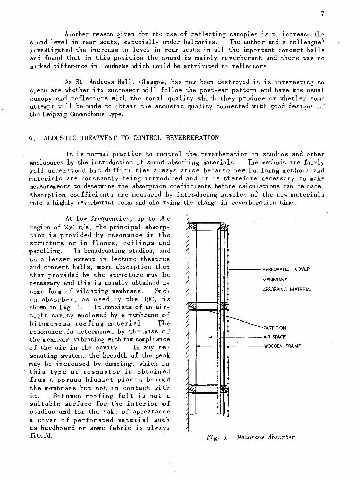
At low frequencies, up to the region of 250 cls, the principal absorption is provided by resonance in the structure or in floors, ceilings and panelling. In broadcasting studios, and to a lesser extent in lecture theatres and concert halls, more absorption than that provided by the structure may be necessary and this is usually obtained by some form of vibrating membrane. Such an absorber, as used by the BBC, is shown in Fig. 1. It.consists of an airtight cavity enclosed by a membrane of bitumenous roof{ng material. The resonance is determined by the mass of the membrane vibrating with the compliance of the air in the cavity. In any resonating system, the breadth of the peak may be increased by damping, which in this type of resonator is obtained from a porous blanket placed behind the membrane but not in contact with it. Bitumen roofing felt is not a suitable surface for the interior of studios and for the sake of appearance a cover of perforated material such as hardboard or some fabric is always fitted.
/
/~ /
/
/
/ /
/
/
/
/
/
/
Hs;;
; / /
/ /
; / /
; / /
/
/t;(;; /
~ / ,--
::
, " :
:
:
;.
--,
, :
r--------
PERFORATED COVER
MEMBRANE
ABSORBING MATERIAL
PARTITION
AIR SPACE
WOODEN FRAME
Fig. i-Membrane Absorber

8
A variation of this which is used when the visible surface must be decorated and without holes consists of a hardboard or plywood panel with roofing felt glued to the rear. The other type of absorber, which has already been mentioned, is the Helmholtz resonator which can take the form used in the old churches of Scandinavia, although more convenient forms are now available. A very common form of Helmholtz resonator consists of a cavity in the corner of a room communicating with the room by means of a slit. This slit is arranged so that it can be adjusted in width and also has a resistive material inserted to control the damping of the resonator; Helmholtz resonators are particularly useful for absorbing isolated normal modes.
Middle and high frequency absorption is normally obtained from porous materials such as draperies and carpets. Where more absorption is required in these frequency regions than can be obtained by normal furnishings, it is customary to use porous blankets of glass fibre, rockwool or cellulose materials: since these materials are not decorative they are normalLy covered by a perforated cover or some form of fabric. The maximum upper frequency at which absorption takes place is controlled by the percentage of open area in the perforated cover. In the BBC, a form of wideband absorber is frequently used which consists of a thick porous blanket over a partitional construction which absorbs down to quite low frequencies. Sound which goes through the blanket is attenuated and reflected from the rear walls, and is absorbed or attenuated on returning through the blanket. Thepartitional construction makes the absorber operate efficiently at low frequencies because it prevents the transverse movement of air behind the blanket. Another type of wideband absorber, shown in Fig. 2, is a combination of absorbers. The outermost absorber consists of a thin membrane over a layer of porous polyurethane foam and this acts as a resonant membrane absorber at high frequencies. Behind the polyurethane there is a perforated backing which permits sound to penetrate to the porous absorber which deals with the middle frequencies, and behind this again there is a normal roofing
FRAMES.
FILLET.
THIN POLYMER MEMBRANE.
POLYURETHANE SPONGE.
PERFORATED HARDBOARD (SLOTS.)
ROCKWOOL.
PERFORATED HARDBOARD (HOLES.)
Fig. 2 - Multiple Absorber
felt absorber for low frequencies.
10. ACOUSTICS OF SMALL ROOMS
When discussing reverberation it was pointed out that in small rooms the low frequency normal modes are isolated and consequently, as they lie in the frequency region of speech, they can cause unpleasant colourations. They also make acoustic treatment rather difficult and general bass absorption sometimes is not sufficient to eliminate the worst colourations. When this happens the best solution is to employ sharply tuned resonators of the Helmholtz type. It is quite common practice now to provide a cavity with a slit in the corner of the room which can be adjusted to eliminate the most prominent normal mode.

9
11. LECTURE THEATRES
Lecture theatres present a problem in acoustics which has been with us for many years. Usually they are constructed with tiers of seats facing the lecturer and the ceiling may be shaped to reflect sound from the lecturer to the audience. If absorption is required on the back or side walls it should be randomly distributed to improve the diffusion. A disadvantage of this approach, which does not often arise in teaching theatres, is that it is not easy for the members of the audience to take part in discussions. For theatres to be used for discussions such as occur in the various learned societies, it is necessary for anybody in any part of the theatre to be able to be heard throughout. This resembles very much a problem of the concert hall where uniform sound distribution is necessary and the solution is similar.
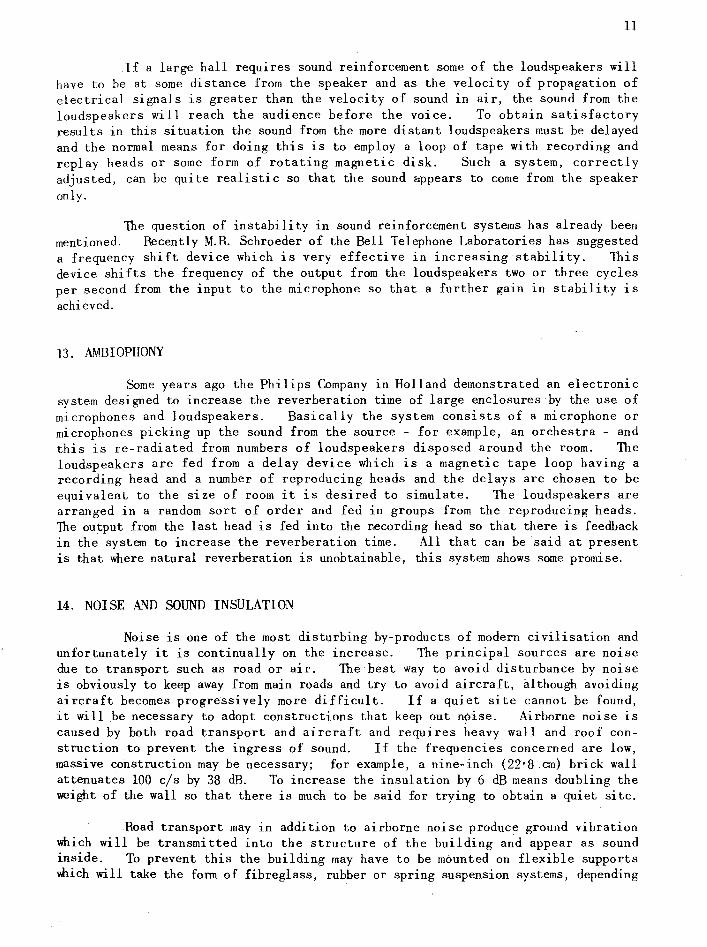
All interesting example of this problem ar9se recently when the lecture theatre of the Institution of Electrical Engineers was reconstructed. Fig. 3 shows a section of this theatre, the line of the old ceiling being dotted in. The acoustical form of the old ceiling was rather bad as it had coves between the ceiling and walls, and as the structure was found to be unsafe it was removed and replaced by a lower ceiling. This ceiling was designed to carry some sound absorption and was made in a irregular form to give good diffusion. The original theatre had panelled walls which, being highly reflecting, resulted in confusion of speech although the bass absorption was adequate. As part of the reconstruction side galleries were introduced which in addition to providing more accommodation provided sound absorbing areas in the middle of the side walls and are most effective in preventing the most troublesome reflections. It is possible in this theatre for a speaker with a reasonable voice to be heard throughout, no matter whe~e he is. Unfortunately most speakers appear to have poor voices, so, in common with most other audience enclosures, sound reinforcement is provided.
12. SOUND REINFORCEMENT
It is customary now in all places where the public is to be addressed to provide sound reinforcement. This applies to quite small rooms where one is always surprised that many people cannot make themselves heard. The first sound reinforcement systems consisted of many loudspeakers arranged aTound the room and usually the result was worse than the complaint, unless one happened to be very close to a loudspeaker. The theory is now better understood and loudspeakers consisting of columns of cone units are now used. The virtue of the loudspeaker column is that it has a very narrow polar diagram in the vertical plane. It is therefore possible to direct the sound down on to the audience and prevent unwanted radiation upwards, to be subsequently reflected as reverberant sound. For most small enclosures two such columns are usually sufficient, placed on either side of the speaker and arranged so that the minimum amount of sound is directed towards the microphone. This is necessary because the limit in any sound reinforcement system is the point of instability at which sufficient energy is picked up by the microphone from the loudspeakers to make the system 'howl'. A further improvement in stability can be obtained by the use 'of directional microphones.
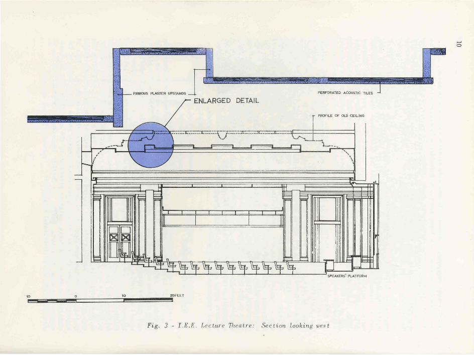
FIBROUS PLASTER UPSTANDS PERFORATED ACOUSTIC TILES
~wJ ENLARGED DETAIL
-....,.;H'''''''~;;;-·....l~~ ~m PROFILE OF OLD CEILING
~
_ ~~_.f~ -: :-:::=I:::-_ .... ::::u:::-:::::.\~]::::_-:::lC.:::-_-:rr:::=-:.:r.=____ \...1-"'--_
1 _____ -'"1
I- , --, , ,
~ , \
r-i \
---
~ ~ ~ E
~ = ;;;;
i I IT 1 1 11 1 I' , ,
, I1 D D I 1
I m!
I i' 1 ! ,11 II8D 0, I I 0
li I [' 1
-Ill I;:: ~ ~ tt: "" J .... " ==I == -
~~~~~~~~ [ J sPEAKERS PLATFORM
1;;.0 !!!!Iiiiiil!!!!!!!!Iiiiiil!!!!!!:O =====j10~!!!!!!!!!!!!!!!!!!!!!!!!!!!!!!!!!!!!!!!!!!20FEET c: "
Fig . 3 - LE .E. Lecture Theatre: Section looking west
...... o
11
If a large hall requires sound reinforcement some of the loudspeakers will have to be at some distance from the speaker and as the velocity of propagation of electrical signals is greater than the velocity of sound in air, the sound from the loudspeakers will reach the audience before the voice. To obtain satisfactory results in this situation the sound from the more distant loudspeakers must be delayed and the normal means for doing this is to employ a loop of tape with recording and replay heads or some form of rotating magnetic disk. Such a system, correctly adjusted, can be quite realistic so that the sound ~ppears to come from the speaker only.
The question of instability in sound reinforcement systems has already been mentioned. Recently M.R. Schroeder of the Bell Telephone Laboratories has suggested a frequency shift device which is very effective in increasing stability. This device shifts the frequency of the output from the loudspeakers two or three cycles per second from the input to the microphone so that a further gain in stability is achieved.
13. AMBIOPHONY
Some years ago the Phi lips Company in Holland demonstrated an electronic system designed to increase the reverberation time of large enclosures by the use of microphones and loudspeakers. Basically the system consists of a microphone or microphones picking up the sound from the source - for example, an orchestra - and this is re-radiated from numbers of loudspeakers disposed around the room. The loudspeakers are fed from a delay device which is a magnetic tape loop having a recording head and a number of reproducing heads and the delays are chosen to be equivalent to the size of room it is desired to simulate. The loudspeakers are arranged in a random sort of order and fed in groups from the reproducing heads. The output from the last head is fed into the recording head so that there is feedback in the system to increase the reverberation time. All that can be said at present is that where natural reverberation is unobtainable, this system shows some promise.
14. NOISE AND SOUND INSULATION
Noise is one of the most disturbing by-products of modern civilisation and unfortunately it is continually on the increase.' The principal sources are noise due to transport such as road or air. The best way to avoid disturbance by noise is obviously to keep away from main roads and try to avoid aircraft, although avoiding aircraft becomes progressively more difficult. If a quiet site cannot be found, it will be necessary to adopt constructions that keep out noise. Airborne noise is caused by both road transport and aircraft and requires heavy wall and roof construction to prevent the ingress of sound. If the frequencies concerned are low, massive construction may be necessary; for example, a nine-inch (22·8 cm) brick wall attenuates 100 c/s by 38 dB. To increase the insulation by 6 dB means doubling the weight of the wall so that there is much to be said for trying to obtain a quiet site.
Road transport may in addition to airborne noise produce ground vibration which will be transmitted into the structure of the building and appear as sound inside. To prevent this the building may have to be mounted on flexible supports Which will take the form of fibreglass, rubber or spring suspension systems, depending

12
BRICK
4-t in .
11·4 cm.)
AIR SPACE
2 in. (5-1 cm
PLASTER • ',.: _t . , .. , BREEZE
'- )" .•. "\ f-I------ BLOCK ~ "'t l 7( 3 in. - ~ r',,-' (7-6 cm.)
, (\- ... ~a
~ ~.
( • r---. ,-. .. . -' r
~~ -:\ ~ t 'I.:~,
• 0 • ,,-: ,,;. ..
CORK I in.
(2-5 cm)
MICROPHONE SKIRTING
Fig_ 4 - Floating floor and wall construction
FIBROUS LAGGING
LIGHT-WEIGHT CONCRETE
2in. (5'1 cm)
TO OTHER STUDIOS
1 I
STUDIO/ ~ "1Z:::::::::z::z:z::z:::;:::::z::z:z::Z:z::::z:::z:::;:::::z:::z:::lq----~:::::::--OUTLET-f./..r::::z:=========L ___ ~
CANVAS BELLOWS VANES TO
I PRESERVE __ -----rkr-r---------, STREAMLINE
PLENUM CHAMBER
FLCIN
CANVAS
I-I'I'II--.
acows 'tJ))
MOUNTINGS
Fig_ 5 - Schematic diagram of sound isolation Ln a ventilation system

13
on the conditions on the site. In broadcasting premises it is often necessary to have studios which require much quieter conditions than are normally available and which may have to be built in buildings used as offices. In this case the studio is built inside a box floated on some flexible support. Such a suspension system is shown in Fig. 4. It will be seen that the floor rests on a fibreglass mat, the walls are carried on cork and the ceiling is supported from the walls.
Structures designed to keep out noise can have no direct access for ventilation, hence forced ventilation systems must then be employed. These require very special design because the fans may produce vibration which can be transmitted through the structure or along the ducts with the air supplying the rooms. Consequently the fans and motors have to be mounted flexibly. They must be isolated from the ducting by flexible connections and the ducts must be lined with absorbent ~aterial to prevent the transmission of sound through them. Such a system is shown in Fig. 5.
15. REFERENCES
1. Sabine, W.C., 'Collected Papers on Acoustics', Harvard University Press, 1922.
2. Somerville, T. and Ward, F.L., 'Investigation of Sound Diffusion 1n Rooms by Means of a Model', Acustica, Vol. 1, 1951, page 40.
3. Haas, H., 'On the Influence of a Single Echo on the Intelligibility of Speech', Acustica, Vol. 1, No. 1, 1951, page 49.
4. Somerville, T., 'A Comparison of the Acoustics of the Philharmonic Hall, Liverpool, and St. Andrews G~and Hall, Glasgow', BBC Quarterly, Vol. IV, No. 1, April 1949, page 1.
BM
5. Somerville, T. and Gilford, C.L.S., 'Acoustics of Large Orchestral Studios and Concert Halls', Proceedings of the I.E.E., Vol. 104, Part B, No. 14, March 1957, page 85.

Printed by B.B.e. Research Department, Klngsyood Warren, Tadworth, Surrey