archaeological trench evaluation and resistivity …
TRANSCRIPT
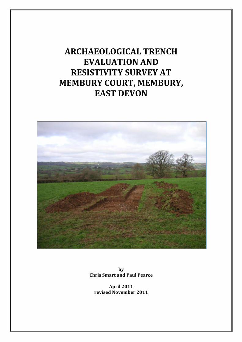
ARCHAEOLOGICAL TRENCH EVALUATION AND
RESISTIVITY SURVEY AT MEMBURY COURT, MEMBURY,
EAST DEVON
by Chris Smart and Paul Pearce
April 2011
revised November 2011
2
Contents Summary 1. Introduction 6 1.1 Site description 1.2 Land use 1.3 Geology and soils 1.4 Archaeological and historical background 2. Aims 9 3. Method 9 3.1 Trench evaluation 3.2 Resistivity survey 4. Results 11 4.1 Trench evaluation 4.2 Resistivity survey 5. Finds 17 6. Discussion 20 7. Recommendations 23 8. Project archive 23
Acknowledgements 23 References 24
Appendix 1. Finds from the evaluation Appendix 2. Finds from surface collection Appendix 3. Devon County Council Brief Figure 1. Site location Figure 2. An extract of Lady Fox’s OS field record sheet Figure 3. The site as depicted on historic mapping of 1891 and 1906 Figure 4. The site as depicted on mapping of 1963 and 1988 Figure 5. Trench location plan Figure 6. Trench 1 plan and section Figure 7. Trench 2 plan and section Figure 8. Trench 3 plan and section Figure 9. Location of resistivity survey in relation to magnetometer survey Figure 10. Greyscale plot of raw resistivity data Figure 11. Greyscale plot of processed resistivity data
3
Figure 12. Colour scale plot of processed resistivity data Figure 13. Relief plot of processed resistivity data Figure 14. Interpretation of resistivity data Figure 15. Combined interpretation of resistivity and excavated data Figure 16. Location where finds recovered from cultivated area of Field 1 Plates 1 and 2. Trench 1 general views across archaeological features Plates 3 and 4. Trench 1, detail of masonry and robber trench [103] Plate 5. Trench 1, detail of robber trench [105]
4
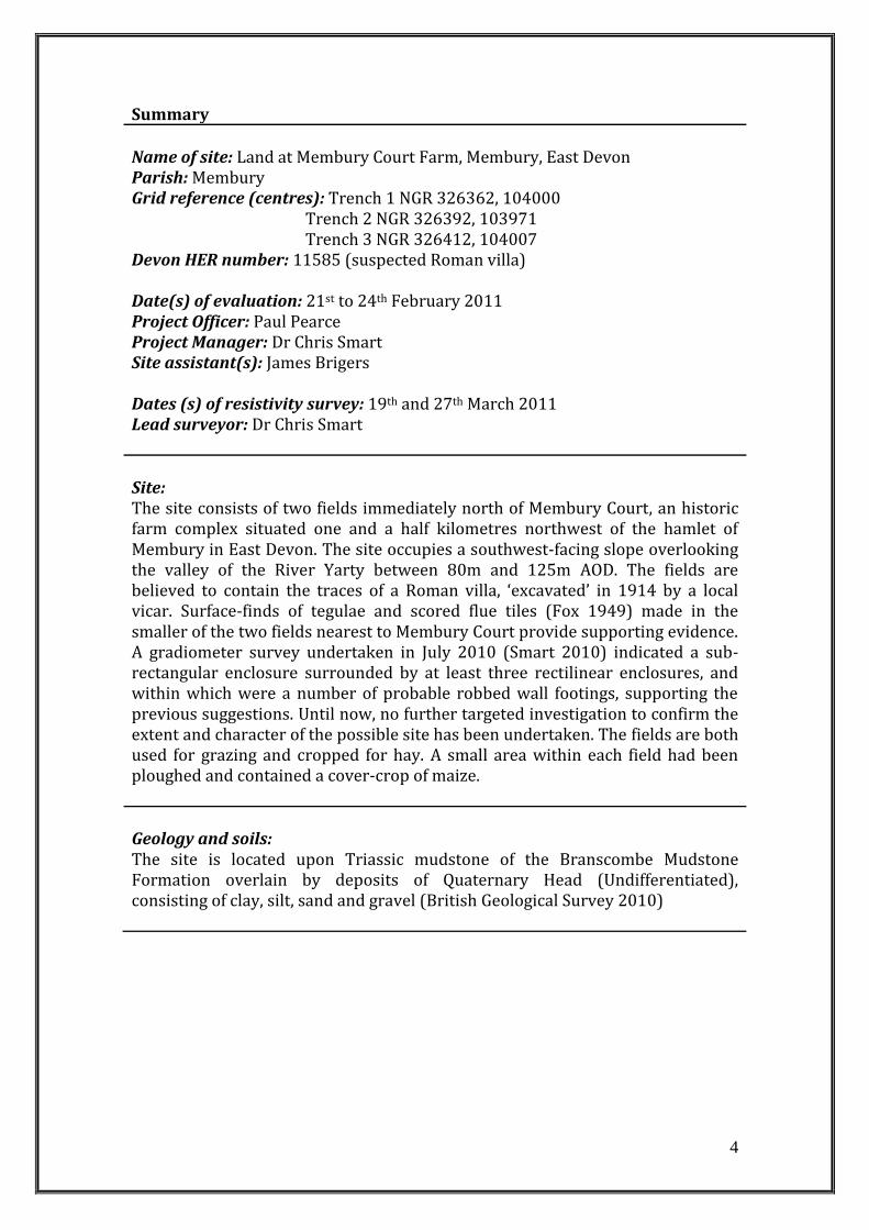
Summary
Name of site: Land at Membury Court Farm, Membury, East Devon Parish: Membury Grid reference (centres): Trench 1 NGR 326362, 104000 Trench 2 NGR 326392, 103971 Trench 3 NGR 326412, 104007 Devon HER number: 11585 (suspected Roman villa) Date(s) of evaluation: 21st to 24th February 2011 Project Officer: Paul Pearce Project Manager: Dr Chris Smart Site assistant(s): James Brigers Dates (s) of resistivity survey: 19th and 27th March 2011 Lead surveyor: Dr Chris Smart
Site: The site consists of two fields immediately north of Membury Court, an historic farm complex situated one and a half kilometres northwest of the hamlet of Membury in East Devon. The site occupies a southwest-facing slope overlooking the valley of the River Yarty between 80m and 125m AOD. The fields are believed to contain the traces of a Roman villa, ‘excavated’ in 1914 by a local vicar. Surface-finds of tegulae and scored flue tiles (Fox 1949) made in the smaller of the two fields nearest to Membury Court provide supporting evidence. A gradiometer survey undertaken in July 2010 (Smart 2010) indicated a sub-rectangular enclosure surrounded by at least three rectilinear enclosures, and within which were a number of probable robbed wall footings, supporting the previous suggestions. Until now, no further targeted investigation to confirm the extent and character of the possible site has been undertaken. The fields are both used for grazing and cropped for hay. A small area within each field had been ploughed and contained a cover-crop of maize.
Geology and soils: The site is located upon Triassic mudstone of the Branscombe Mudstone Formation overlain by deposits of Quaternary Head (Undifferentiated), consisting of clay, silt, sand and gravel (British Geological Survey 2010)
5
Investigation type: Trench evaluation Number of trenches: 3 (Trench 1 = 13.6m, Trench 2 = 11.2m, Trench 3 = 10.1m) Area evaluated: 48.1 m2 The evaluation was done in accordance with English Heritage and Institute for Archaeologists guidelines. Survey type: Electrical resistance (resistivity) survey Equipment: GeoScan Research RM15 with MPX15 multiplexer Configuration: Twin parallel, 3 probe Area surveyed: 0.52ha Grid size: 20m by 20m Traverse method: Zig-Zag Traverse interval: 0.5m Sample interval: 0.5m The survey and reporting was done in accordance with English Heritage guidelines Geophysical Survey in Archaeological Field Evaluation (2008).
Results: Three trenches were positioned to investigate archaeological features indicated by a previous geophysical (magnetometer) survey (Smart 2010). Trench 1 revealed a pair of robber trenches suggested by the survey. In addition four walls were identified, two of which formed a room with internal plaster rendering. It is suggested that this building is of a Romanised form, and the range of building materials employed and evidence for a heating system suggest that this is of considerable local status. It possibly represents the location of a villa or associated building. Trench 2 revealed the northern ditch of a substantial sub-rectangular enclosure, posited on morphological grounds to be of Late Iron Age or Early Roman date. Excavation offered little dateable material but yielded a small assemblage of metal-working debris and a piece of ?Roman roofing slate. Trench 3 revealed a pair of enclosure ditches already indicated by the geophysical survey. These were part of a rectilinear enclosure system. Pottery and building debris from these are consistent with a Roman date. Overall, the evaluation confirmed the presence of features identified by geophysical (magnetometer) survey and in addition revealed a series of masonry walls indicative of a Romanised building. Targeted resistivity survey placed the masonry building in a wider context and showed that it was likely to actually be an ancillary building, possibly a bath house, with the main ‘villa’ building to the south. The site appears to be that of a rural farmstead which has progressively expanded to include a rectilinear enclosure system and has adopted the trappings of Roman Britain.
6
1. INTRODUCTION
This report has been prepared for Devon County Council and presents the results of an archaeological trench evaluation and targeted electrical resistance survey (resistivity) of land at Membury Court, Membury, East Devon (Figure 1; ST 26364 03803). The investigation was commissioned by Devon County Council and was carried out in accordance with a Brief issued by Cressida Whitton, Archaeologist, Devon County Council Historic Environment Service (DCCHES Ref. Arch/AE/ED/17777). The purpose of the trench evaluation and resistivity survey was to further characterise the form, nature and depth of any sub-surface archaeological remains indicated by a previous magnetometer survey (Smart 2010), in order to inform appropriate decision and management in response to proposed harrowing and re-seeding of the land. 1.1 Site description The site consists of two fields immediately north of Membury Court, an historic farm complex situated one and a half kilometres northwest of the hamlet of Membury in East Devon. Membury is a small parish in the southeast corner of the Blackdown Hills, north of the Roman, and later, medieval small town of Axminster. The historic settlement pattern of this region is characterised by a multitude of small farms dispersed between a number of hamlets and small villages such as Membury and Stockland. It is a rich agricultural landscape dominated by dairying and beef-production with only scant arable cultivation. The sites stretches across a southwest-facing slope, between 125m and 80m AOD, overlooking the valley of the River Yarty. The upper part of the site slopes gently, reducing to a near-level plateau between the two fields and breaking to a steeper angle approximately half way down the lower field. The level area between the two fields is coincident with the suggested position of the ‘villa’ site. At this point the ground was noticeably firm underfoot and the grass was stunted compared to that on the surrounding slopes. Discussion with the tenant farmer also revealed that during aeration of the ground using a spiked roller, he had determined a good depth of soil across the fields but noted that there were only shallow soils in this area. What he believed to be near-surface geology could alternatively be derived from any structures that may have stood in this area. The fields in this area are enclosed by Devon hedge banks with mature deciduous trees growing upon them. The semi-irregular curvilinear morphology of this block of fields may derive from the enclosure of cultivation strips, as suggested in the Devon County Council Historic Landscape Characterisation (http://gis.devon.gov.uk/basedata/viewer.asp?DCCService=hlc), although it is possible that the character of the fields is a product of the irregular topography of the undulating valley sides above the River Yarty and a tributary stream that enters it to the west of Membury Court. From here the Yarty valley extends northwards into the Blackdown Hills and south to Axminster. The River Yarty enters the English Channel at Axmouth, 15km downstream.
7
1.2 Land use When evaluated and surveyed both fields were under permanent grass. The grass in Field 1 had been recently cut to a short length, but that in Field 2 was approximately 0.2m in length. 1.3 Geology and soils The site is positioned on a tract of Quaternary Head (Undifferentiated), consisting of clay, silt, sand and gravel, overlaying Triassic mudstone of the Branscombe Mudstone Formation. On higher ground to the north of the site, and also across the small tributary valley to the south of Membury Court, the underlying geology changes to Greensand and Chalk overlain by Clay-with-Flints (British Geological Survey 2010). 1.4 Archaeological and historical background In 1914 the Reverend F.E.W. Langdon, vicar of Dalwood Parish, is believed to have dug part of a “Roman villa” in a field to the north of Membury Court, although no primary records of his investigation are known (Hoskins 1954). In support of these reports, Roman tegulae and scored flue tiles were collected from the surface of ‘Brickfield’ in 1948 and given to the Royal Albert Memorial Museum, Exeter (Fox 1949, 88), although these cannot currently be found (Cadbury pers. comm.). In 1957 the site was visited by Stuart Rigold, from the Inspectorate of Ancient Monuments, who was told by the farmer at that time that the site was ‘on the top of a little hill looking south’, which was ‘covered with fragments of tile and stone and the grass is still visibly thin’ (letter from Rigold to Lady Fox dated 2/12/57, copy in DCCHER). In 1959 Aileen Fox (subsequently Lady Fox) visited the site as part her work with the Ordnance Survey Archaeology Division (Figure 2). The exact position of the supposed villa was not known but she remarked that shallow depressions may be the remains of the Reverend’s 1914 diggings (DCCHER PRN 11585). ‘Brickfield’ later became known at ‘Culver Croft’ and in 1967 a further fragment of possible Roman tile was found in the roots of a fallen tree in the hedgerow of this field by Dawn Walker (DCCHER ST20SE/22), who visited the site after reading in the log book of the parish school that finds from a possible Roman villa had been shown to the children at the beginning of the 20th century. This provides corroborative evidence for Langdon’s investigation but unfortunately the whereabouts of the logbooks are not now known. A geophysical (magnetometer) survey of the two fields in which the site is suspected to sit, funded by Natural England, revealed significant multi-period buried archaeological remains (Smart 2010). The range of features revealed by this survey includes at least three rectilinear enclosures, a fourth sub-rectangular double-ditched enclosure and the possible foundation trenches of a rectangular building. In the light of previous investigations at the beginning of the 20th century, it was suggested that this is likely to be the site of the Roman “villa” excavated by the Reverend Langdon, and that the enclosures are of similar date. Furthermore, it was proposed that the development of the settlement and enclosure complex may have begun in the Late Iron Age. It was also mooted that the magnetic survey may not have revealed the full extent of structural remains.
8
Relict elements of the historic landscape were also observed, and it would appear that the pattern of fields present in the landscape today were once further subdivided. Indeed, changes to the historic field pattern can be seen through an examination of historic maps. The historic landscape surrounding Membury Court consists of semi-irregular fields, some of which have a curving form that appear to follow the direction of the topography. Although these fields have been characterised as ‘medieval enclosures based on strip fields’ in the Devon County Council Historic Landscape Characterisation (http://gis.devon.gov.uk/basedata/viewer.asp?DCCService= Hlc; Turner 2007), their curving morphology may have been determined by the local terrain. They are, however, likely to be of medieval date (ibid.; Rippon et al. 2006a). Consultation of historic mapping dating from the 19th century onwards shows that the site has undergone some reorganisation. The 1843 parish Tithe map, which predates the first Ordnance Survey mapping by almost fifty years, and the First Edition Ordnance Survey 6inch mapping, dated 1891 (Figure 3), both show that the site consists of four semi-irregular curvilinear fields. The long-axes of each field runs down-slope, and the curving elements appear to follow the orientation of the contours. This differs from today’s landscape in that three of the fields have now been amalgamated. A series of footpaths are indicated, which run north from Membury Court and east-west between West Mill and Furley Farm. Many of the small closes around Membury Court are orchards. Second Edition Ordnance Survey 6inch mapping, dated 1906 (Figure 3), shows that by this time there had been no internal alterations to the arrangement shown on the First Edition. All boundaries appear the same and have undergone no significant alteration. The closes which surround Membury Court remain as orchard. Ordnance Survey 1:10560 1st Imperial Edition mapping of 1963 (Figure 4) shows that the landscape illustrated on late nineteenth century mapping was unchanged. The next available Ordnance Survey mapping is dated 1988, and by this time there has been considerable change. The 1891, 1906 and 1963 mapping showed that the site comprised four fields, but at some point between 1963 and 1988 three fields were agglomerated into a single large and irregular-shaped parcel of land (called Field 2 for the purpose of the survey) through the removal of two sinuous hedgebanks. It appears that no changes have been made to the boundaries of the field nearest to Membury Court (called Field 1 for the purpose of the survey) between 1891 and the present day. Royal Air Force vertical aerial photographs taken in 1947 were examined (4314 RAF AP CPE/UK1974IIAPR47F20//MULTI(4)16400 frame 31/45 and 4315 RAF AP CPE/UK1974IIAPR47F20//MULTI(4)16400 frame 31/46). Nothing of archaeological interest is visible in the immediate vicinity of the suspected site, although a series of stone-filled land drains are clearly visible and appear to be newly-dug. The only features in the wider setting that are of apparent significance is a linear earthwork running north-east from farm buildings at Membury Court. This appears to follow the contours and whilst it may represent the line of a trackway it is more likely to be a leat, or similar, that took water from the adjacent stream into the farm complex.
9
2. AIMS The principal aim of the project is to establish the character, date and depth of buried archaeological remains hinted at by the historical record and recent magnetometer survey. This targeted evaluation was limited in extent and as such the results may not be fully representative of the character of all buried archaeological remains revealed by geophysical survey and that may remain unrealised. Recommendations for appropriate management to protect the archaeological resource will be made by Devon County Council Historic Environment Service to Mr and Mrs Denny and Natural England, based on the results of this work. 3. METHOD 3.1 Trench evaluation Three trenches totalling 33m in length were excavated using a tracked mechanical excavator fitted with a 1.2m-wide toothless grading bucket. The trenches were positioned in accordance with the location roughly indicated in the Devon County Council Brief, Figure 1 and more precisely according to the geo-referenced results of the geophysical survey. Trench 1 was placed to investigate the potential robbed wall foundations at NGR 326364.7850, 103999.3440. Trench 2 was placed to provide a section across the northern side of the sub-rectangular enclosure at NGR 326392.9220, 103968.3600. Lastly, Trench 3 was positioned to provide a transect across two probable ditches which form part of a rectilinear enclosure complex at NGR 326411.6790, 104007.3830, which straddles both Fields 1 and 2. The trench end-points were fixed using a Leica TCR1200 Total Station EDM in relation to known reference points. Four permanent datum points, consisting of 0.45m wooden pegs, were located around the site boundary at the time of the magnetometer survey in order to provide a lasting reference from which the position of any archaeological features can be measured in the future. The position of these pegs in relation to the Ordnance Survey National Grid was determined using a Leica 1200 series differential GPS. The NGR co-ordinates for these points are given in Table 1, below, and are shown on Figure 5. Accordingly, the NGR for each trench end-point was established to an accuracy of +/_ 0.05m (Table 2, below). Table 1. National Grid Reference co-ordinates for permanent datum points at Membury
Court Point ID NGR Easting NGR Northing
Reference point 1 326392.5083 104004.1338
Reference point 2 326293.8810 103967.6482
Reference point 3 326393.4699 104006.0776
Reference point 4 326525.4230 104995.3666
10
Table 2. National Grid Reference co-ordinates for evaluation trench plan datum points at Membury Court
Point ID NGR Easting NGR Northing
Trench 1 NW end 326356.6772 104004.6611
Trench 1 SE end 326367.9006 103996.7444
Trench 2 N end 326393.4759 103975.6424
Trench 2 S end 326392.5538 103966.6410
Trench 3 WNW end 326407.9648 104008.3030
Trench 3 ESE end 326415.7735 104006.4934
Removal of topsoil and colluvium continued until either natural subsoil or archaeological deposits were reached. Where archaeological deposits were exposed, trenches were cleaned back by hand, and the deposits investigated and recorded using standard methods accepted by DCC and the IfA. Stratigraphic information was recorded on pro-forma single context recording sheets and a drawn record was made at scales of 1:10 and 1:20 as appropriate. A photographic record of the evaluation was made in black and white film and colour digital format. 3.2 Resistivity survey An area of approximately 0.52ha was subject to electrical resistance (resistivity) survey. Resistivity survey was selected as a proven method of accurately detecting archaeological features, but particularly walls, surfaces and areas of debris. The survey was undertaken in accordance with English Heritage guidelines presented in Geophysical Survey in Archaeological Field Evaluation (2008). 3.2.1 Survey Design Eleven 20m by 20m survey grids were set-out in relation to the position of known archaeological features and were positioned to maximise coverage in the available time. They were set-out on an approximate northwest-southeast / northeast-southwest axis. The grid corner points were laid with an internal accuracy of +/- 0.05m. The grids in Field 1 and Field 2 were laid independent of each other. The survey grids were located according to the Ordnance Survey National Grid using a Leica System 1200 differential Global Positioning System that has a typical three-dimensional global position accuracy of 10-15mm. National Grid Reference co-ordinates for each of the grid points is given in Appendix 1. The resistivity survey was undertaken using a GeoScan RM15 resistivity meter coupled with a MPX15 multiplexer, utilising a three probe parallel twin configuration sampling two readings per metre at 0.5m traverse intervals. The traverses were sampled in a zig-zag pattern. The direction of the first traverse was northeast. 3.2.2 Data Processing The resistivity survey data was downloaded to an IBM-compatible laptop computer directly into GeoPlot 3.0. The same software was used for data processing.
11
The electrical resistance data presented in Figures 11-13 was processed as follows: Despike: X radius =1, Y radius = 1, Threshold = 3.0, Spike replacement = mean Interpolate: Direction = Y. Mode = expand, Expand method = Sin X/X. 4. RESULTS 4.1 Trench evaluation Three trenches were excavated with the aim of investigating features previously identified as likely to be of archaeological significance by an earlier programme of geophysical survey (Smart 2010). The objectives were to provide further information regarding the likely nature and date of the features, and to establish the depth of soil cover present, in order to inform practices of land management. Trench 1 (Figure 6; Plates 1-5) The trench was aligned approximately north-west to south-east, and targeted the site identified as a probable building in Field 1. The trench initially measured 13.6m long by 1.2m wide, but was subsequently extended by the opening of an additional 4.6m long, 1.2m wide area to the south-west of the south-eastern end. Removal of the turf from the south-eastern portion of the trench immediately exposed a series of substantial rubble wall footings within which some phasing was apparent (Building 1). The upper surface of these archaeological deposits sat only 0.14m below the present ground surface. The alignment of the walls suggests a south south-west-facing aspect to the building and their spatial arrangement clearly defined several rooms within a range. The earliest part of the exposed structure was represented by wall 106, constructed within a terrace cut into the hillslope, the surface of the natural clay being slightly below the top of the surviving fabric on the north-eastern side. The wall was 0.8m wide and the fabric comprised large pieces of chert rubble, with occasional undressed greensand (some heat discoloured) present in the south-western facing, bonded with an extremely hard, dark greenish-grey mortar. Abutting the south-east end of wall 106 was a narrower wall, 107, 0.55m wide and bonded with a yellowish greensand mortar, which extended 90 degrees south-west to enclose one room (Room 1). Whilst the dimensions of this Room 1 were not realised, the interior facing retained a 13-15mm thick layer of mortar render around much of the visible extent. The interior was filled with robbing debris (102) that extended around the demolished north-western end of wall 106, and continued without differentiation into a 0.55m-wide and 0.3m deep linear robber trench [103] that extended beyond the north-eastern edge of the trench. The alignment of this robber trench was not perpendicular with the alignment of walls 106 and 107, which again may reflect phasing within the structure. A second robber trench [105], 0.8m wide and 0.3m deep, was located 3.1m northwest of [103] and ran
12
parallel to it. It was filled with a single deposit of robbing debris (104). Both deposits of robbing debris (102) and (104) comprised a similar dark yellowish-brown loam containing quantities of tile, mortar, plaster (including painted fragments), irregular chert and small greensand pieces, and, rarely, fragments of dark grey shaley slate. A single piece of heat discoloured, but apparently worked, Ham stone was recovered from (102). A small sondage c. 0.4m deep was excavated through the robbing debris (102) within Room 1, to the southwest of wall 106, with the objective of establishing whether any in situ flooring survived, or, if not, at what height it had been. This revealed that the layer of render applied to the inner face of wall 106 extended 0.37m below the surviving top of the wall, and probing with the point of a trowel suggested that the base of the wall lay perhaps some 20mm or so beneath that. No ridge, arras, or scar was present to suggest that any floor had been present at any level below the existing top of the render, and neither was the render keyed or coated. At the base of the robbing debris (102) was a deposit of very fine and sticky dark brownish-grey silt, containing frequent fragments of comminuted tile and charcoal (111) but it could not be established whether this continued beneath the base of wall 106 or butted up against it. Two further sections of masonry, 108 and 110, abutted wall 106, both of which are likely to be later additions. Each comprised unbonded chert rubble, and appeared to be footed on the natural clay, rather than cut in as 106 had been, although neither was excavated. Wall 108 was 0.6m wide and appeared to extend the line of wall 106 further east south-east, continuing beyond the end of the trench after little more than a metre. Wall 110 extended northeast of wall 106, but only 0.3m was visible between it and the trench edge. It appeared to have a width of c. 0.7m. Surrounding, and in places covering the walls, was an extensive, although locally patchy, deposit of dark yellowish-brown loam (101) that thickened towards the north-western end of the trench to form a more consistent layer 0.13m thick between the natural clay (112) and the topsoil. It was unclear whether this represented colluvium or the base of a former cultivation soil, but it had, however, clearly been cut by the episodes of robbing represented by trenches [103] and [105]. Trench 2 (Figure 7) A c.10m long trench, aligned approximately north to south, was opened over the line of the east - west ditch that formed the northern side of an ovoid enclosure (Enclosure 1) seen during the magnetometer survey in Field 1. Archaeological features in this trench were covered by a minimum of 0.3m of topsoil and colluvium. The enclosure ditch [204] was 2.45m wide at the top and 1m deep with a slightly steeper southern (inside) edge and a rounded base. The presence of groundwater was noted during hand-excavation of the upper 0.2m of the ditch and increased significantly with depth, causing instability of the ditch sections. As such, machine excavation was employed to empty the base of the ditch in
13
order to establish the full profile and recover finds. The fills comprised two more-or-less undifferentiated deposits, and in each of which no significant layering was evident. The lower fill, (203), comprised a 0.4m thick deposit of densely packed, and mainly small, angular chert fragments in a matrix of reddish-brown silty clay with much manganese staining that increased towards the base. The deposit extended for some distance up the sides of the cut and appeared to be the result of natural weathering. The upper fill, (202), comprised a 0.65m thick deposit of similar composition, but containing a greater proportion of larger chert pieces in a matrix of compact greyish- to yellowish-brown silty clay. Three pieces of iron slag and four pieces of fired clay were recovered from this deposit, along with two small pieces of dark grey slate and a small quantity of residual worked chert and flint of prehistoric date. Towards the northern edge of the ditch a thin layer of charcoal, (205), was present at the interface between (202) and the colluvium, (201), which separated it from the topsoil above. The colluvium comprised a stony, dark yellowish-brown loam that elsewhere within the trench lay directly on top of the natural deposits. The depth of colluvium increased gradually from 0.15m at the northern end of the trench to 0.26m at the southern; the exception to this was to the north of ditch [204] where a linear hollow in the natural Head deposits (206), parallel with the line of the ditch, had infilled with this material to a depth of 0.4m. It is uncertain exactly what activity has resulted in the hollow but the geophysical survey hints at a possible outer boundary, concentric to that which was investigated. Trench 3 (Figure 8) A c.10m long trench aligned approximately north-west to south-east was placed to investigate the north-south aligned ditches of two adjacent enclosures (Enclosures 2 and 3) located against the south-western edge of Field 2. The trench was located 30m east of Trench 1. Archaeological features in this trench were covered by a minimum of 0.3m of topsoil and colluvium. As with Trench 2, the presence of groundwater became an issue during the excavation of the deeper ditch of the western enclosure, and as before, machine excavation was employed in order to empty the base of the ditch in order to establish the full profile and recover finds. The westernmost enclosure ditch [304] was 2.8m wide at the top and 0.95m deep, the open profile having a slightly steeper western (inner) edge, and a very gently rounded and slightly irregular base. A small shelf was present on the eastern edge of the ditch cut, the base of which lay some 0.32m below the top of the ditch, and which could conceivably represent the base of a smaller predecessor containing fill (309), which comprised a 0.15m thick deposit of grey silty clay with frequent small chert pieces. The basal fill, (303), comprised a 0.4m thick deposit of compact grey silty clay with frequent small, and occasional large, fragments of chert. Fill (303) yielded seven pieces of tile, including keyed flue tile, and four pieces of Black Burnished-ware. The tertiary fill, (302), consisted of a 0.4m thick deposit
14
of dark greyish- to yellowish-brown loam with small chert pieces and occasional charcoal flecks. The western ditch of the eastern enclosure, [308], proved to be 0.7m deep with a flattish base. The moderately-sloping sides of the ditch flared to give a wide and somewhat shallow profile to the upper part, some 3.3m from edge to edge. The basal fill, (307), comprised a 0.3m thick deposit of compact silty clay and small chert fragments with rare charcoal, tile, and slate in addition to a small fragment of volcanic trap and a single sherd of unclassified oxidised coarse ware. The upper fill, (306), comprised 0.4m of mid- to dark yellowish-brown loam with frequent small chert pieces and rare charcoal, tile, and slate. Sealing the upper fills of both ditches and the natural Head deposits (309), and separating these from the base of the topsoil above, was a c. 0.2m thick layer of stony, dark yellowish-brown colluvium, (301), similar to that in Trench 2. 4.2 Resistivity survey (Figures 9-14) The electrical resistance survey (resistivity) within Field 1 was focussed on evaluation trench 1, where robber trenches and a range of in situ walls were recorded. It also extended across the centre of the rectilinear enclosure revealed by the magnetometer survey, the northern ditch of which was recorded in evaluation trench 2. The work has revealed a palimpsest of buried archaeological remains, and has proven to be the most effective geophysical technique in established the position, form and extent of probable masonry buildings, demolition debris and stone-packed ditches. Background resistance readings within the area surveyed in Field 1 are in the range of 19 to 25 ohms, with the majority of archaeological features yielding responses of higher magnitude. The highest response reached 76 ohms, approximately 300% of mean background resistance. The principal features will be discussed in a logical sequence, and will be followed by general observations. The results show that the masonry remains recorded in Trench 1 were part of a structure, measuring at least 19m square, although it may be rectangular in plan (A) (Building 1). The position of the trench itself shows as an area of lower relative resistance, as would be expected due to the loose soil-rich backfill. The same axis of the principal wall (106) recorded in Trench 1 was identified by the survey, and showed a magnitude of up to 38 ohms in the immediate locale, but reached 48 ohms towards its west-northwest end. It is suggested that this disparity is a combined result of differential robbing and extents of rubble backfill surrounding the walls. Only faint traces of the wall-line can be identified in and beyond the west-northwest edge of Trench 1, which corresponds well to an increased depth of robbing seen here. The results show at least five linear arrays of readings between 38 and 59 ohms running ninety degrees from wall (106), two of which probably represent the northwest and southeast external walls, and three that possibly represent internal divisions (B). The spacing of these indicates internal spaces of approximately 4m width. A cautionary note is that there is the possibility that these are cultivation scars, identified because of the high-resistance material through which they cut. Only one lateral high-resistance feature running parallel
15
to wall (106) is identifiable, situated almost central within the building. There are no distinct traces of additional in situ masonry to the southwest of wall (106), despite recognition of at least one room here in Trench 1. There are, however, elevated readings in the same area, which probably derive from the demolition and/or robbing debris that was recorded there. Approximately 20m south-west of the building partially revealed in Trench 1 is a rectilinear arrangement of high magnitude readings that range between 50 and 85 ohms (C) (Building 2). There are two key observations to be made first of all. The elevated readings here are 200-300% of the background immediately surrounding them, and are significantly greater than the responses given by known in situ masonry further north. The nature of these high readings is indicative of a second, larger building, slightly downslope of Building 1. The arrangement suggests a building with a linear northern range, oriented approximately east-west, with two principal north-south ‘wings’ to each end. Whilst the eastern ‘wing’ appears to be concurrent with the eastern gable of the main range, the western ‘wing’ projects beyond the western gable, indicating a degree of structural complexity to the range. Furthermore, a series of additions are possibly indicated by rectilinear arrangements of readings in the range 50 to 62 ohms, to the north of the main range and on the eastern face of the east ‘wing’. The size and morphology of these anomalies, if they represent the location of a building, are consistent with a modest Roman winged-corridor villa. It is notable that although the outline of a building range is almost certain, no individual wall-lines are prominent, especially compared to those associated with walls in Building 1. The reason for this is that there are equally high readings throughout the area, which prohibits the identification of clear contrasts, and this is likely to be due to either, or a combination of, in situ floor surfaces and masonry demolition debris (unlike the soil-rich robber-debris (102) which infilled Room 1 within Building 1). If this interpretation is correct, then it suggests that Building 1 is an ancillary structure and this area of high resistance represents the location of the principal building. Areas of medium-high resistance immediately to the north and south of the main range (D) are likely to represent spreads of debris, although the readings do not preclude the presence of structural additions or small ancillary buildings. An isolated area of high resistance readings (E), measuring approximately 8m by 3m, 7m from the northwest corner of the probable ‘villa’ appears to have no discernible form, although the readings are of a similar magnitude to areas of suggested masonry/rubble. This also corresponds to an area of heightened magnetic disturbance recorded in the magnetometer survey (Smart 2010), which may be due to ground disturbance or a spread of thermoremanent material (brick, tile etc). The resistance survey has identified part of the sub-rectangular enclosure (Enclosure 1) first identified during the magnetometer survey and evaluated in Trench 2. A section of the eastern ditch can be identified (F), and corresponds with the northern terminus of the entrance on that side. Similarly, a section of the western ditch is visible, and can be seen extending south from the western ‘wing’ of the probable building (G). The high resistance response of the enclosure
16
(53-70 ohms) is contra that ordinarily expected from an infilled ditch, but this is explained by the densely-packed stone fill recorded in Trench 3. If the identification of the large building is correct then it is apparent that it was constructed over the northwest corner of the enclosure, and this is supported by evidence from the resistivity survey and excavation that suggests that the ditch had been deliberately backfilled. Furthermore, the previous magnetometer survey showed that the ditch here is less prominent, and now it can be suggested that this is because of its fill and what overlay it (Smart 2010). The results show that the buildings are enclosed by a series of rectilinear boundaries to the north and west (H). This feature has resistance readings above the background norm, which suggests that the boundary comprises a masonry wall or stone bank. However, we have seen that the ditch of the sub-rectangular enclosure returned a high-resistance response due to the nature of its infill, and again it is possible that the boundary consists of a ditch infilled with densely-packed stone. It is apparent that this rectilinear boundary extends northeast into Field 2, where it joins a wider network of similar features. There can be little reasonable doubt that the boundary is contemporary with the Roman building/s already discussed, but a certain antiquity is also implied by the fact that the boundary predates the medieval field pattern. Only a small area of Field 2, immediately northeast of the historic field boundary, was surveyed and the full extent of the rectilinear boundary pattern is not known, although the form and distribution of higher-magnitude readings suggests that buried features extend beyond the limits of the two grids surveyed. The course of the boundary features in Fields 1 and 2 identified by the resistance survey was not revealed by the magnetic survey, probably indicating that these comprise walling or stone banks. It is notable, however, that the general axes of these are comparable with the rectilinear ditch system identified by the magnetometer survey, which again indicates that the two elements are likely to be contemporary. There are some broad observations that can also be made to support the integrity of the interpretations already discussed. First, there is a clear demarcation between the background resistance and areas of enhanced magnitude. This divide is concurrent with the rectilinear boundary that encloses the range of buildings. It may be suggested that the whole area contained by these has been modified. It is possible that compaction, made-ground, or surfaces has contributed to the broader increase in resistance in the vicinity of the building complex. Furthermore, there are linear areas of higher resistance within the enclosure complex, and it is apparent that one extends between Buildings 1 and 2, and a second arcing around the western side of Building 2 to its northern side. It seems probable that these represent trackways or yard-surfaces between and giving access to each building. A series of regularly-spaced striations, running approximately north-south, are visible across the area of high resistance (I). These vary between 40 and 52 ohms in resistance and are interpreted as cultivation marks. It is probable that they are distinct here because ploughing has cut through and spread high-resistance material in the direction of cultivation. A curvilinear east-west anomaly (J) appears to cut through the probable building, and is highlighted as an area of
17
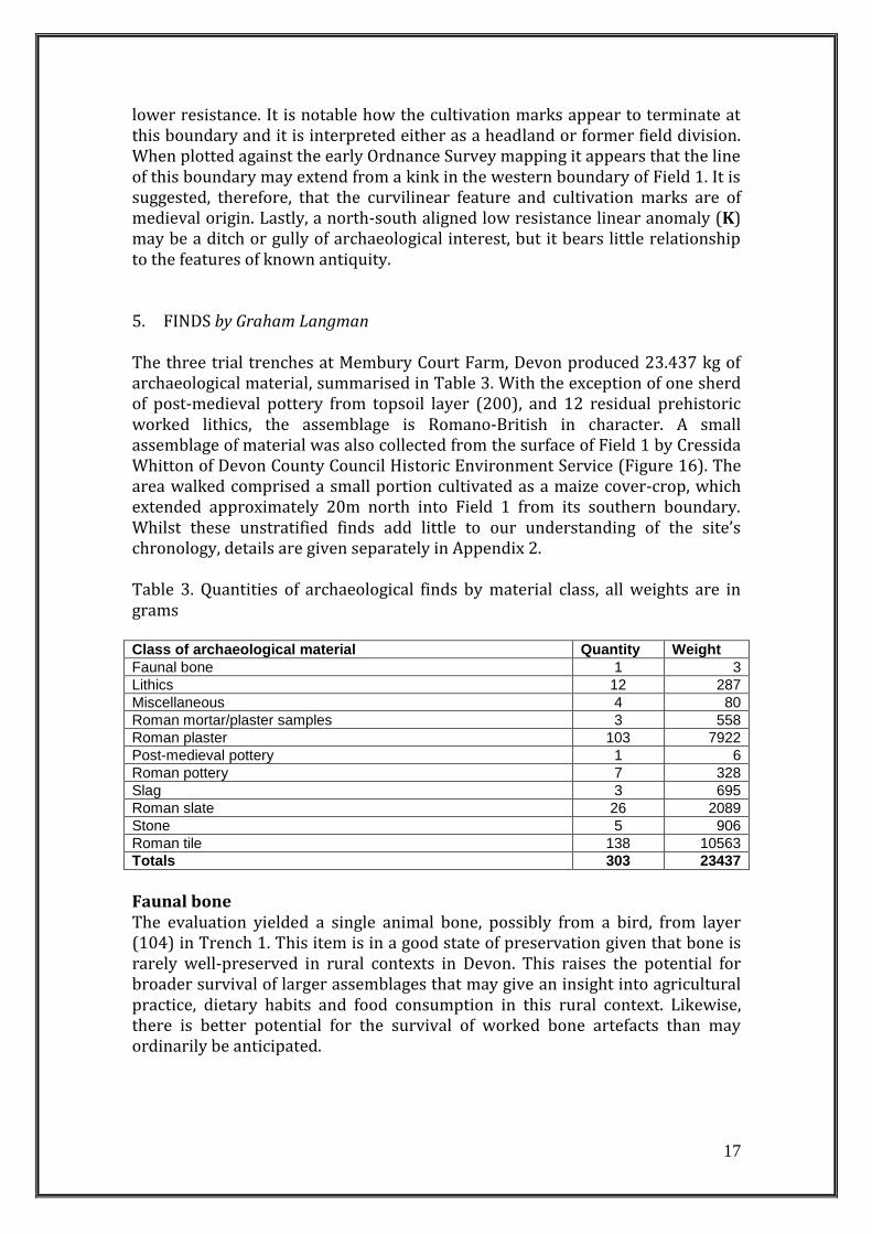
lower resistance. It is notable how the cultivation marks appear to terminate at this boundary and it is interpreted either as a headland or former field division. When plotted against the early Ordnance Survey mapping it appears that the line of this boundary may extend from a kink in the western boundary of Field 1. It is suggested, therefore, that the curvilinear feature and cultivation marks are of medieval origin. Lastly, a north-south aligned low resistance linear anomaly (K) may be a ditch or gully of archaeological interest, but it bears little relationship to the features of known antiquity. 5. FINDS by Graham Langman The three trial trenches at Membury Court Farm, Devon produced 23.437 kg of archaeological material, summarised in Table 3. With the exception of one sherd of post-medieval pottery from topsoil layer (200), and 12 residual prehistoric worked lithics, the assemblage is Romano-British in character. A small assemblage of material was also collected from the surface of Field 1 by Cressida Whitton of Devon County Council Historic Environment Service (Figure 16). The area walked comprised a small portion cultivated as a maize cover-crop, which extended approximately 20m north into Field 1 from its southern boundary. Whilst these unstratified finds add little to our understanding of the site’s chronology, details are given separately in Appendix 2. Table 3. Quantities of archaeological finds by material class, all weights are in grams Class of archaeological material Quantity Weight
Faunal bone 1 3
Lithics 12 287
Miscellaneous 4 80
Roman mortar/plaster samples 3 558
Roman plaster 103 7922
Post-medieval pottery 1 6
Roman pottery 7 328
Slag 3 695
Roman slate 26 2089
Stone 5 906
Roman tile 138 10563
Totals 303 23437
Faunal bone The evaluation yielded a single animal bone, possibly from a bird, from layer (104) in Trench 1. This item is in a good state of preservation given that bone is rarely well-preserved in rural contexts in Devon. This raises the potential for broader survival of larger assemblages that may give an insight into agricultural practice, dietary habits and food consumption in this rural context. Likewise, there is better potential for the survival of worked bone artefacts than may ordinarily be anticipated.
18
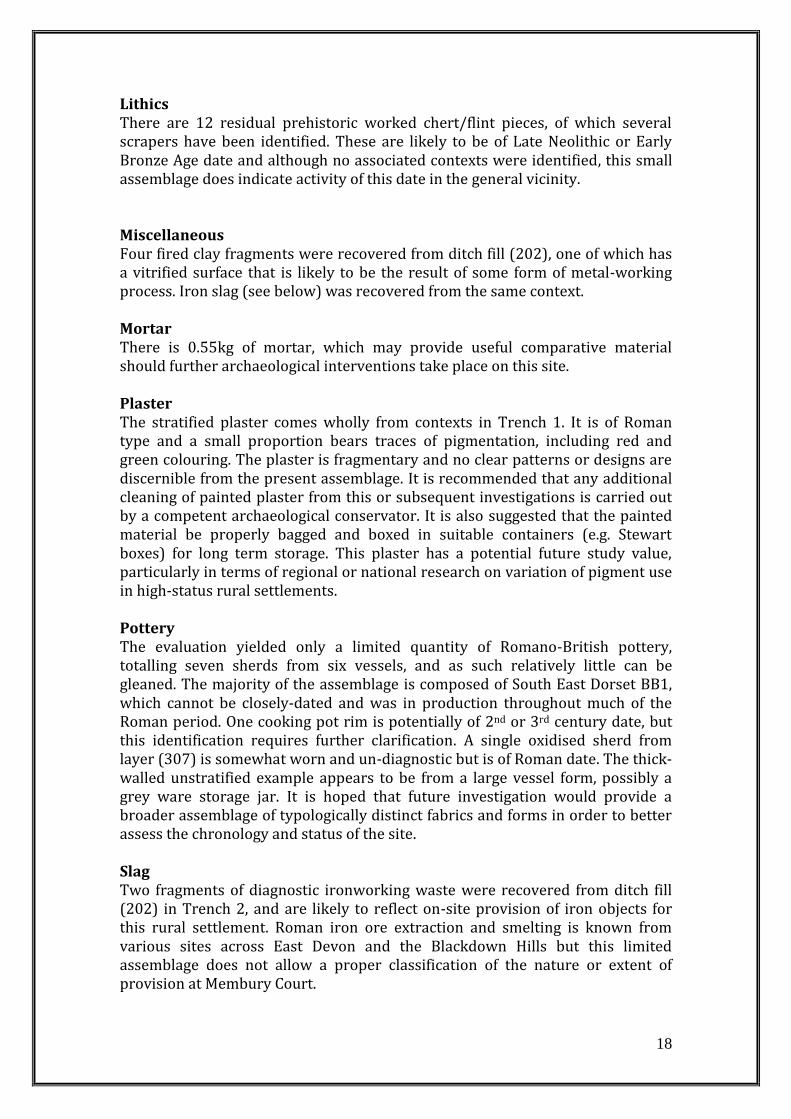
Lithics There are 12 residual prehistoric worked chert/flint pieces, of which several scrapers have been identified. These are likely to be of Late Neolithic or Early Bronze Age date and although no associated contexts were identified, this small assemblage does indicate activity of this date in the general vicinity. Miscellaneous Four fired clay fragments were recovered from ditch fill (202), one of which has a vitrified surface that is likely to be the result of some form of metal-working process. Iron slag (see below) was recovered from the same context. Mortar There is 0.55kg of mortar, which may provide useful comparative material should further archaeological interventions take place on this site. Plaster The stratified plaster comes wholly from contexts in Trench 1. It is of Roman type and a small proportion bears traces of pigmentation, including red and green colouring. The plaster is fragmentary and no clear patterns or designs are discernible from the present assemblage. It is recommended that any additional cleaning of painted plaster from this or subsequent investigations is carried out by a competent archaeological conservator. It is also suggested that the painted material be properly bagged and boxed in suitable containers (e.g. Stewart boxes) for long term storage. This plaster has a potential future study value, particularly in terms of regional or national research on variation of pigment use in high-status rural settlements. Pottery The evaluation yielded only a limited quantity of Romano-British pottery, totalling seven sherds from six vessels, and as such relatively little can be gleaned. The majority of the assemblage is composed of South East Dorset BB1, which cannot be closely-dated and was in production throughout much of the Roman period. One cooking pot rim is potentially of 2nd or 3rd century date, but this identification requires further clarification. A single oxidised sherd from layer (307) is somewhat worn and un-diagnostic but is of Roman date. The thick-walled unstratified example appears to be from a large vessel form, possibly a grey ware storage jar. It is hoped that future investigation would provide a broader assemblage of typologically distinct fabrics and forms in order to better assess the chronology and status of the site. Slag Two fragments of diagnostic ironworking waste were recovered from ditch fill (202) in Trench 2, and are likely to reflect on-site provision of iron objects for this rural settlement. Roman iron ore extraction and smelting is known from various sites across East Devon and the Blackdown Hills but this limited assemblage does not allow a proper classification of the nature or extent of provision at Membury Court.
19
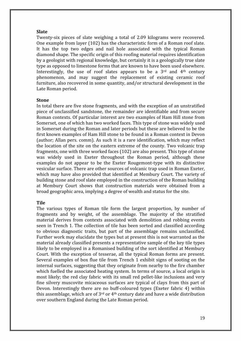
Slate Twenty-six pieces of slate weighing a total of 2.09 kilograms were recovered. One example from layer (102) has the characteristic form of a Roman roof slate. It has the top two edges and nail hole associated with the typical Roman diamond shape. The specific origin of this roofing material requires identification by a geologist with regional knowledge, but certainly it is a geologically true slate type as opposed to limestone forms that are known to have been used elsewhere. Interestingly, the use of roof slates appears to be a 3rd and 4th century phenomenon, and may suggest the replacement of existing ceramic roof furniture, also recovered in some quantity, and/or structural development in the Late Roman period. Stone In total there are five stone fragments, and with the exception of an unstratified piece of unclassified sandstone, the remainder are identifiable and from secure Roman contexts. Of particular interest are two examples of Ham Hill stone from Somerset, one of which has two worked faces. This type of stone was widely used in Somerset during the Roman and later periods but these are believed to be the first known examples of Ham Hill stone to be found in a Roman context in Devon (author; Allan pers. comm). As such it is a rare identification, which may reflect the location of the site on the eastern extreme of the county. Two volcanic trap fragments, one with three worked faces (102) are also present. This type of stone was widely used in Exeter throughout the Roman period, although these examples do not appear to be the Exeter Rougemont-type with its distinctive vesicular surface. There are other sources of volcanic trap used in Roman Exeter, which may have also provided that identified at Membury Court. The variety of building stone and roof slate employed in the construction of the Roman building at Membury Court shows that construction materials were obtained from a broad geographic area, implying a degree of wealth and status for the site. Tile The various types of Roman tile form the largest proportion, by number of fragments and by weight, of the assemblage. The majority of the stratified material derives from contexts associated with demolition and robbing events seen in Trench 1. The collection of tile has been sorted and classified according to obvious diagnostic traits, but part of the assemblage remains unclassified. Further work may elucidate the types but at present this is not warranted as the material already classified presents a representative sample of the key tile types likely to be employed in a Romanised building of the sort identified at Membury Court. With the exception of tesserae, all the typical Roman forms are present. Several examples of box flue tile from Trench 1 exhibit signs of sooting on the internal surfaces, suggesting that they originate from nearby to the fire chamber which fuelled the associated heating system. In terms of source, a local origin is most likely; the red clay fabric with its small red pellet-like inclusions and very fine silvery muscovite micaceous surfaces are typical of clays from this part of Devon. Interestingly there are no buff-coloured types (Exeter fabric 4) within this assemblage, which are of 3rd or 4th century date and have a wide distribution over southern England during the Late Roman period.
20
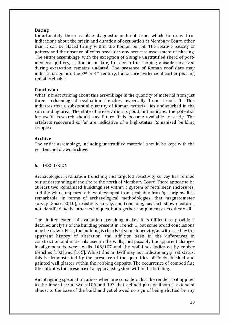
Dating Unfortunately there is little diagnostic material from which to draw firm indications about the origin and duration of occupation at Membury Court, other than it can be placed firmly within the Roman period. The relative paucity of pottery and the absence of coins precludes any accurate assessment of phasing. The entire assemblage, with the exception of a single unstratified sherd of post-medieval pottery, is Roman in date, thus even the robbing episode observed during excavation remains undated. The presence of Roman roof slate may indicate usage into the 3rd or 4th century, but secure evidence of earlier phasing remains elusive. Conclusion What is most striking about this assemblage is the quantity of material from just three archaeological evaluation trenches, especially from Trench 1. This indicates that a substantial quantity of Roman material lies undisturbed in the surrounding area. The state of preservation is good and indicates the potential for useful research should any future finds become available to study. The artefacts recovered so far are indicative of a high-status Romanised building complex. Archive The entire assemblage, including unstratified material, should be kept with the written and drawn archive.
6. DISCUSSION Archaeological evaluation trenching and targeted resistivity survey has refined our understanding of the site to the north of Membury Court. There appear to be at least two Romanised buildings set within a system of rectilinear enclosures, and the whole appears to have developed from probable Iron Age origins. It is remarkable, in terms of archaeological methodologies, that magnetometer survey (Smart 2010), resistivity survey, and trenching, has each shown features not identified by the other techniques, but together compliment each other well. The limited extent of evaluation trenching makes it is difficult to provide a detailed analysis of the building present in Trench 1, but some broad conclusions may be drawn. First, the building is clearly of some longevity, as witnessed by the apparent history of alteration and addition seen in the differences in construction and materials used in the walls, and possibly the apparent changes in alignment between walls 106/107 and the wall-lines indicated by robber trenches [103] and [105]. Whilst this in itself may not indicate any great status, this is demonstrated by the presence of the quantities of finely finished and painted wall plaster within the robbing deposits. The occurrence of combed flue tile indicates the presence of a hypocaust system within the building. An intriguing speculation arises when one considers that the render coat applied to the inner face of walls 106 and 107 that defined part of Room 1 extended almost to the base of the build and yet showed no sign of being abutted by any
21
form of flooring. The render was not keyed or coated in any way, and in a room that seems to have been finely finished with painted plaster, this may suggest that the lower, plain render coating was not intended to be visible and may have existed beneath the level of a suspended floor. In view of the fact that the apparent base of the structure, beneath robbing debris (102), was covered in a deposit of fine charcoal and tile fragments (111), it is tentatively proposed that this room may have had a hypocaust, notwithstanding the fact that nothing of it’s size, shape, and relative position in the building is as yet known. Whilst no pottery or metalwork of any kind was recovered from any of the excavated contexts associated with the building, it should be noted that these were made only through post-abandonment deposits and that no interventions were made through material associated with the building’s construction or use. Given the limited extent of the current investigation this apparent lack of domestic material need not preclude domestic occupation here, or elsewhere on the site, in the context of a villa. Indeed, the broader evidence provided by the resistivity survey shows that the building identified during the evaluation is likely to be ancillary to the principal range, which sits 20m to the south. The position, aspect, and apparent level of finish of Building 1 indicates that it is more than a simple agricultural building, and it is plausible to suggest that it may be a detached bath house or other high-status structure. The suggestion that Building 1 is not the principal habited building is supported by the lack of domestic pottery revealed during the investigation of it. The probable morphology of Building 2 is suggests that it is a winged-corridor type, although there appear to be a number of additions. At this stage it is not possible to ascertain the plan of any building with certainty, or indeed phasing or chronology, but it is common for such sites to have numerous structural phases associated with expansion, development and rebuilding over time. The three enclosures that were evaluated all seem to have been current during the life of the Romanised building seen in Trench 1, but the sub-rectangular enclosure (1) to the south is likely to be earlier than the larger and more rectilinear enclosures (2) and (3) to the east. The ditches of the latter both contained significant quantities of Romano-British building material within their lower fills but such material was absent from ditch [204] of enclosure 1. The general appearance of this enclosure, in contrast to the rectilinear arrangement of those to the east of the building, may support the suggestion that settlement commenced at a much earlier point in time than that suggested by the later phases of the building, and subsequently developed in extent and Romanised character. It is notable that the fill of ditch [204] was heavily packed with large pieces of chert, the local country rock, which accounts for the high-resistance response returned by the feature during the resistivity survey. Building 2, which is proposed to be the principal domestic structure within the complex, had been constructed over the northwest corner of enclosure 1, supporting the suggestion that it had been actively backfilled prior to the construction of the Romanised building complex and that the site is multiphase, probably with Iron Age origins. There appears to be at least two elements to the later rectilinear phase of enclosure associated with the Romanised buildings, the first of which are the larger field enclosures identified during the magnetometer survey (Smart 2010).
22
The second are the linear boundaries identified by the resistivity survey, which appear to define the extent of the building complex. The two appear to be congruous and share the same general north-west / south-east axis. Together, these boundaries seem to enclose the settlement core, and also define a series of small ?stock enclosures around it. There is the possibility, however, that elements of this system may be linked with an earlier phase associated with enclosure 1. There are a number of sites comparable to the Membury Court complex known in the locality, as well as further afield, for example the nearby villas at Holcombe (Pollard 1974), at Honeyditches, Seaton (Silvester 1981), at Otterton Point, Budleigh Salterton (Brown and Holbrook 1989), as well as the Romanised complex at Whitestaunton further north on the Blackdown Hills (Somerset HER 53262), and at Yarford, Kingston St Mary (Wilkinson et al. 2003). Locally, there are several significant scatters of Roman pottery, notably at Yarty Farm and Crib House, with a Roman corn-drier excavated at the latter (Tingle 2006). It is clear that the Roman site at Membury Court does not sit in isolation but is one element of an extensively settled valley landscape. The villa at Holcombe had at least three structural phases, and was a direct replacement for a preceding Iron Age settlement. Significantly, the villa was constructed over the Iron Age enclosure ditch, the upper fills of which also appear to have been consolidated with large stone pieces (see Pollard 1974, plate I for example). It was also apparent that here walls associated with the villa had been built to fill the full profile of the Iron Age ditch (ibid. plates XVIII and XIX for example) and a similar construction method could be expected at Membury. Excavation has showed that Holcombe was furnished with an elaborate bath complex on the western end of the villa, which some have suggested is disproportionate to the residential part (Smith 1978, 134). The limited evidence from Membury Court perhaps suggests that there was a detached bath house situated to the north of the main residence, although only excavation will elucidate the actual character of Buildings 1 and 2. No bath complex has been securely identified at Yarford villa, on the southern edge of the Quantocks in western Somerset, but the site does offer a striking parallel for the villa at Membury Court. At Yarford, a double-ditched D-shaped enclosure was surrounded by a series of rectilinear enclosures, which were thought to possibly represent occupation and agriculture in the Late Iron Age and Roman periods. A magnetometer survey confirmed the extent of the enclosure system but failed to identify the villa building. This was only identified through excavation of the D-shaped enclosure. Again, the villa had been constructed over the earlier Iron Age ditched enclosure, and the presence of Valentinianic coins suggests activity until at least the end of the Roman period (Wilkinson et al. 2003). The occupation of villa sites in general can often be somewhat open ended, and in this case, as in many, there is nothing that precludes occupation and development of the building over a considerable period of time from humble beginnings dating back to at least the earlier Romano-British period. Further work would need to be undertaken to establish at which point occupation of the site began and finally ceased; broad analogy suggests that the site may have origins in the Late Iron Age and may have continued in use into the late 4th
23
century or beyond. Specifically, any future work should consider the careful hand-excavation and scientific dating of uppermost deposits, which elsewhere are beginning to reveal a picture of occupation into the 5th century and beyond (at Dinnington villa in southeast Somerset, C14 dating of burnt grain shows that occupation continued until at least the latter part of the 5th century (Gallagher 2005)).
7. RECOMMENDATIONS
The purpose of the evaluation and resistivity survey was to further clarify the extent, character and chronology of the site in order to assess its local, regional and national significance, and to inform decisions about management of the site. It is clear that the site represents a Romanised settlement, almost certainly including a villa and ancillary buildings set within a series of agricultural enclosures. Although a number of villas are known on the south side of the Blackdown Hills in East Devon, sites of this type must be considered a rarity and afforded protection as such. Excavation of Trench 1 in the lower of the two fields at Membury Court showed that in situ masonry survived only 0.14m beneath the surface, and as such, it is strongly recommended that any application for cultivation in this field is refused. Trench 3, positioned to investigate associated enclosures in the upper field showed that 0.3m of colluvium sealed the upper surface of archaeological features and deposits. Here, should shallow cultivation be allowed it is thought that this would not be detrimental to the preservation of the known remains but it should be remembered that the existing geophysical survey and this evaluation may not have revealed the full extent or depth of buried archaeological features in either field and decisions should be made with caution.
8. PROJECT ARCHIVE AND OASIS RECORD The project archive will be integrated and prepared in accordance with the guidelines offered by the Royal Albert Memorial Museum, Exeter. Unfortunately at the time of writing a formal request for an accession number, under which to deposit the archive, was declined pending a future decision on RAMM’s acceptance of archives. Until deposition at the RAMM or an alternative repository is arranged the project archive will be held by Dr Chris Smart in the Department of Archaeology at the University of Exeter. A record of the trench evaluation at Membury Court Farm, which will include a .PDF copy of this report, will be submitted to OASIS under the reference drchriss1-97715. ACKNOWLEDGEMENTS Excavation and recording was undertaken by Paul Pearce, James Brigers and Chris Smart. Ben Pears assisted with the setting-out of trenches. Chris Smart undertook the resistivity survey. Thanks are due to Helen Rance and Cressida Whitton who volunteered time to assist in the setting-out of the resistivity survey grids. This report was prepared by Chris Smart (trench evaluation and resistivity survey) and Paul Pearce (trench evaluation) with illustrations
24
prepared by Chris Smart. The initial magnetometer survey was financed by Natural England. The project was co-ordinated and managed by Chris Smart. Graham Langman identified and recorded the finds from the evaluation, and also those collected by C. Whitton from the surface of Field 1. The landowners, Sheena and Lister Denny, are thanked for agreeing to the evaluation and the tenant farmer Trevor Johnson for undertaking the machine-excavation and reinstatement of the ground. Cressida Whitton administered and monitored the work on behalf of Devon County Council. REFERENCES Brown, S. and Holbrook, N. 1989: A Roman Site at Otterton Point. Proceedings of
the Devon Archaeological Society 47, 29-42. English Heritage 2008: Geophysical Survey in Archaeological Field Evaluation. Fox, A. 1949: Sixteenth Report on the Early History of Devon. Transactions of the
Devonshire Association 81, 88. Gallagher, B. 2005: Dinnington, Somerset: an interim report on the archaeological
evaluation by Time Team (unpublished Wessex Archaeology report). Hoskins, W.G. 1954 Devon. A New Survey of England. London: Collins. Pollard, S. 1974: A Late Iron Age Settlement and a Romano-British Villa at
Holcombe, near Uplyme, Devon. Proceedings of the Devon Archaeological Society 32, 59-161.
Rippon, S., Smart, C. and Wainwright, A. 2006a: The Living Past: Archive Report.
Unpublished University of Exeter Report produced for the Blackdown Hills AONB.
Rippon, S.J., Fyfe, R.M. and Brown, A.G. 2006b: Beyond Villages and Open Fields:
the Origins and Development of a Historic Landscape Characterised by Dispersed Settlement in South West England. Medieval Archaeology 50, 31-70.
Silvester, R.J. 1981: Excavations at Honeyditches Roman Villa, Seaton, in 1978.
Proceedings of the Devon Archaeological Society 39, 37-88. Smith, D.J. 1978: Regional Aspects of the Winged Corridor Villa in Britain, in
Todd, M (ed.) Studies in the Romano-British Villa. Leicester, 117-48. Tingle, M. 2006: Excavations of a Possible Causewayed Enclosure and Roman
Site at Membury 1986 and 1994-2000. Proceedings of the Devon Archaeological Society 64, 1-52.
25
Turner, S.C. 2007: Ancient Country : the Historic Character of Rural Devon. Exeter: Devon Archaeological Society.
Wilkinson, K., King, T., Marter, P., Stoodley, N., Turner, A. and Webster, C. 2003:
Archaeological Investigations at Yarford, Kingston St Mary, Somerset April-July 2003. Unpublished report, King Alfred’s College, Winchester and Somerset County Council.
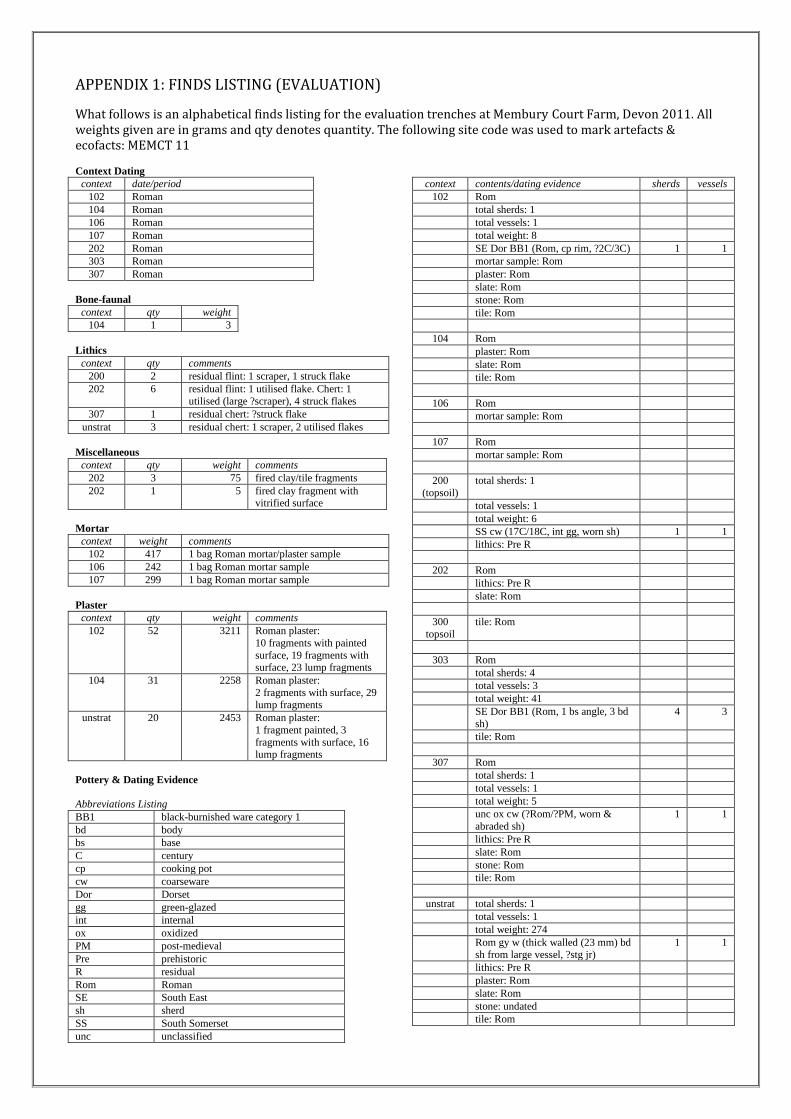
APPENDIX 1: FINDS LISTING (EVALUATION)
What follows is an alphabetical finds listing for the evaluation trenches at Membury Court Farm, Devon 2011. All weights given are in grams and qty denotes quantity. The following site code was used to mark artefacts & ecofacts: MEMCT 11
Context Dating
context date/period
102 Roman
104 Roman
106 Roman
107 Roman
202 Roman
303 Roman
307 Roman
Bone-faunal
context qty weight
104 1 3
Lithics
context qty comments
200 2 residual flint: 1 scraper, 1 struck flake
202 6 residual flint: 1 utilised flake. Chert: 1
utilised (large ?scraper), 4 struck flakes
307 1 residual chert: ?struck flake
unstrat 3 residual chert: 1 scraper, 2 utilised flakes
Miscellaneous
context qty weight comments
202 3 75 fired clay/tile fragments
202 1 5 fired clay fragment with vitrified surface
Mortar
context weight comments
102 417 1 bag Roman mortar/plaster sample
106 242 1 bag Roman mortar sample
107 299 1 bag Roman mortar sample
Plaster
context qty weight comments
102 52 3211 Roman plaster:
10 fragments with painted
surface, 19 fragments with surface, 23 lump fragments
104 31 2258 Roman plaster:
2 fragments with surface, 29 lump fragments
unstrat 20 2453 Roman plaster:
1 fragment painted, 3
fragments with surface, 16 lump fragments
Pottery & Dating Evidence
Abbreviations Listing
BB1 black-burnished ware category 1
bd body
bs base
C century
cp cooking pot
cw coarseware
Dor Dorset
gg green-glazed
int internal
ox oxidized
PM post-medieval
Pre prehistoric
R residual
Rom Roman
SE South East
sh sherd
SS South Somerset
unc unclassified
context contents/dating evidence sherds vessels
102 Rom
total sherds: 1
total vessels: 1
total weight: 8
SE Dor BB1 (Rom, cp rim, ?2C/3C) 1 1
mortar sample: Rom
plaster: Rom
slate: Rom
stone: Rom
tile: Rom
104 Rom
plaster: Rom
slate: Rom
tile: Rom
106 Rom
mortar sample: Rom
107 Rom
mortar sample: Rom
200
(topsoil)
total sherds: 1
total vessels: 1
total weight: 6
SS cw (17C/18C, int gg, worn sh) 1 1
lithics: Pre R
202 Rom
lithics: Pre R
slate: Rom
300
topsoil
tile: Rom
303 Rom
total sherds: 4
total vessels: 3
total weight: 41
SE Dor BB1 (Rom, 1 bs angle, 3 bd
sh)
4 3
tile: Rom
307 Rom
total sherds: 1
total vessels: 1
total weight: 5
unc ox cw (?Rom/?PM, worn &
abraded sh)
1 1
lithics: Pre R
slate: Rom
stone: Rom
tile: Rom
unstrat total sherds: 1
total vessels: 1
total weight: 274
Rom gy w (thick walled (23 mm) bd sh from large vessel, ?stg jr)
1 1
lithics: Pre R
plaster: Rom
slate: Rom
stone: undated
tile: Rom
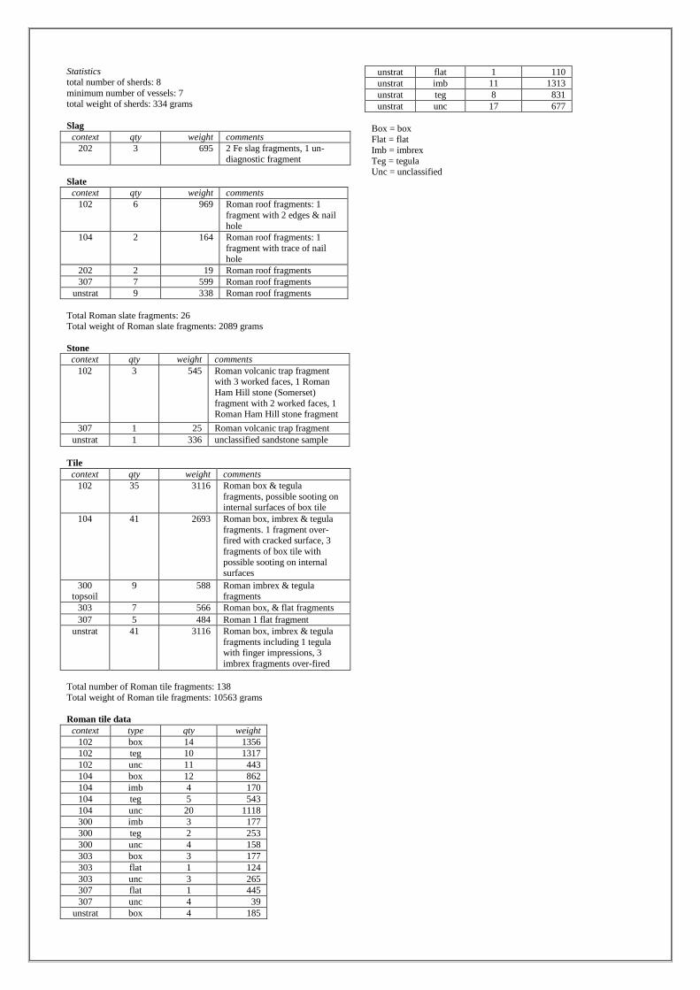
Statistics
total number of sherds: 8
minimum number of vessels: 7
total weight of sherds: 334 grams
Slag
context qty weight comments
202 3 695 2 Fe slag fragments, 1 un-
diagnostic fragment
Slate
context qty weight comments
102 6 969 Roman roof fragments: 1
fragment with 2 edges & nail
hole
104 2 164 Roman roof fragments: 1
fragment with trace of nail
hole
202 2 19 Roman roof fragments
307 7 599 Roman roof fragments
unstrat 9 338 Roman roof fragments
Total Roman slate fragments: 26 Total weight of Roman slate fragments: 2089 grams
Stone
context qty weight comments
102 3 545 Roman volcanic trap fragment with 3 worked faces, 1 Roman
Ham Hill stone (Somerset)
fragment with 2 worked faces, 1 Roman Ham Hill stone fragment
307 1 25 Roman volcanic trap fragment
unstrat 1 336 unclassified sandstone sample
Tile
context qty weight comments
102 35 3116 Roman box & tegula
fragments, possible sooting on internal surfaces of box tile
104 41 2693 Roman box, imbrex & tegula
fragments. 1 fragment over-fired with cracked surface, 3
fragments of box tile with
possible sooting on internal surfaces
300 topsoil
9 588 Roman imbrex & tegula fragments
303 7 566 Roman box, & flat fragments
307 5 484 Roman 1 flat fragment
unstrat 41 3116 Roman box, imbrex & tegula
fragments including 1 tegula with finger impressions, 3
imbrex fragments over-fired
Total number of Roman tile fragments: 138
Total weight of Roman tile fragments: 10563 grams
Roman tile data
context type qty weight
102 box 14 1356
102 teg 10 1317
102 unc 11 443
104 box 12 862
104 imb 4 170
104 teg 5 543
104 unc 20 1118
300 imb 3 177
300 teg 2 253
300 unc 4 158
303 box 3 177
303 flat 1 124
303 unc 3 265
307 flat 1 445
307 unc 4 39
unstrat box 4 185
unstrat flat 1 110
unstrat imb 11 1313
unstrat teg 8 831
unstrat unc 17 677
Box = box Flat = flat
Imb = imbrex
Teg = tegula Unc = unclassified
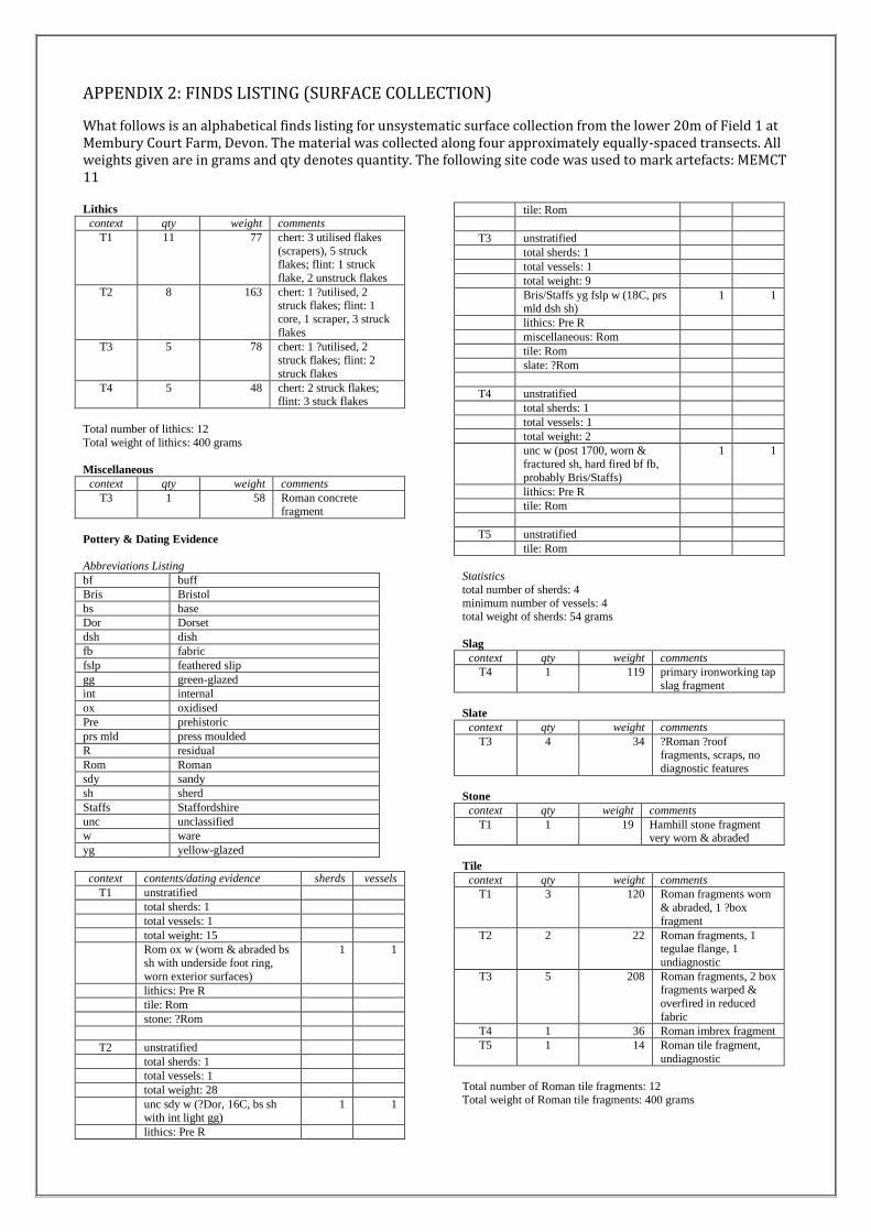
APPENDIX 2: FINDS LISTING (SURFACE COLLECTION)
What follows is an alphabetical finds listing for unsystematic surface collection from the lower 20m of Field 1 at Membury Court Farm, Devon. The material was collected along four approximately equally-spaced transects. All weights given are in grams and qty denotes quantity. The following site code was used to mark artefacts: MEMCT 11 Lithics
context qty weight comments
T1 11 77 chert: 3 utilised flakes
(scrapers), 5 struck flakes; flint: 1 struck
flake, 2 unstruck flakes
T2 8 163 chert: 1 ?utilised, 2 struck flakes; flint: 1
core, 1 scraper, 3 struck
flakes
T3 5 78 chert: 1 ?utilised, 2 struck flakes; flint: 2
struck flakes
T4 5 48 chert: 2 struck flakes; flint: 3 stuck flakes
Total number of lithics: 12
Total weight of lithics: 400 grams
Miscellaneous
context qty weight comments
T3 1 58 Roman concrete fragment
Pottery & Dating Evidence
Abbreviations Listing
bf buff
Bris Bristol
bs base
Dor Dorset
dsh dish
fb fabric
fslp feathered slip
gg green-glazed
int internal
ox oxidised
Pre prehistoric
prs mld press moulded
R residual
Rom Roman
sdy sandy
sh sherd
Staffs Staffordshire
unc unclassified
w ware
yg yellow-glazed
context contents/dating evidence sherds vessels
T1 unstratified
total sherds: 1
total vessels: 1
total weight: 15
Rom ox w (worn & abraded bs
sh with underside foot ring,
worn exterior surfaces)
1 1
lithics: Pre R
tile: Rom
stone: ?Rom
T2 unstratified
total sherds: 1
total vessels: 1
total weight: 28
unc sdy w (?Dor, 16C, bs sh
with int light gg)
1 1
lithics: Pre R
tile: Rom
T3 unstratified
total sherds: 1
total vessels: 1
total weight: 9
Bris/Staffs yg fslp w (18C, prs mld dsh sh)
1 1
lithics: Pre R
miscellaneous: Rom
tile: Rom
slate: ?Rom
T4 unstratified
total sherds: 1
total vessels: 1
total weight: 2
unc w (post 1700, worn &
fractured sh, hard fired bf fb,
probably Bris/Staffs)
1 1
lithics: Pre R
tile: Rom
T5 unstratified
tile: Rom
Statistics
total number of sherds: 4
minimum number of vessels: 4 total weight of sherds: 54 grams
Slag
context qty weight comments
T4 1 119 primary ironworking tap
slag fragment
Slate
context qty weight comments
T3 4 34 ?Roman ?roof
fragments, scraps, no diagnostic features
Stone
context qty weight comments
T1 1 19 Hamhill stone fragment very worn & abraded
Tile
context qty weight comments
T1 3 120 Roman fragments worn
& abraded, 1 ?box
fragment
T2 2 22 Roman fragments, 1 tegulae flange, 1
undiagnostic
T3 5 208 Roman fragments, 2 box fragments warped &
overfired in reduced
fabric
T4 1 36 Roman imbrex fragment
T5 1 14 Roman tile fragment,
undiagnostic
Total number of Roman tile fragments: 12
Total weight of Roman tile fragments: 400 grams
APPENDIX 3: DEVON COUNTY COUNCIL BRIEF FOR ARCHAEOLOGICAL EVALUATION Location: Membury Court Parish: Membury District: East Devon County: Devon NGR: ST26370400 Proposal: Evaluation of geophysical survey results. Possible site of Romanised
building. Historic Environment Service ref: ARCH/AE/ED 17777 1. INTRODUCTION AND ARCHAEOLOGICAL BACKGROUND 1.1 This brief has been prepared by the Devon County Council Historic Environment Service (DCHES) to provide sufficient information for a costed programme of archaeological evaluation to be undertaken at the above site. 1.2 This work is being commissioned by Devon County Council in order to inform land management decisions and future research plans. 1.3 The principal objective of the programme shall be to excavate three evaluation trenches over archaeological features identified in previous geophysical survey (Dr Chris Smart, 2010) and test soil cover over the features. The results will allow the nature, and date of any surviving archaeological deposits to be better understood in order to inform land management as well as possible future survey and research excavation design.
1.4 A Romano-British ‘villa’ has been suspected in the vicinity of Membury Court Farm for some time. The County Historic Environment Record (HER) records the (poorly defined) site of a Roman Villa (HER ref 11585) within the holding, which may have been partially excavated by a local vicar (Rev. F. E. Langdon) in 1914 AD. In 1957, the Archaeologist Lady Fox reported a ’passing reference’ to these excavations (’on top of a little hill, looking south’), in the journal ‘Transactions of the Devonshire Association’ (Vols. 58 & 59) and during a visit to Membury Court, recorded that the hilltop location (ST26420406) of the ‘excavation’ site (apparently covered in tile/stone and thin grass) was pointed out by Mr Rigold, the farmer. In 1948, Hoskins (1954) records that Roman tegulae and scored flue tiles were found at the site and deposited with RAMM (Exeter Museum), however recent investigation at RAMM was unable to locate the tile (Tom Cadbury (Curator), pers. comm.). Hoskins (1954) also refers to the 1914 excavation by Rev. Langdon, but notes that an excavation report was not published. In 1959 the Ordnance Survey Archaeology Division visited the ‘villa site’ and found some shallow depressions in its vicinity, which might represent infilled trenches.
1.5 Membury Court Farm is currently in an Environmentally Sensitive Area (ESA) scheme administered by Natural England (NE). In 2009/10, Mrs Sheena Denny, the landowner applied to NE to resume cultivation of several fields, including two fields (Fields 1 & 2 in Geophysical report) most closely associated with the ‘villa’ site. Whilst a later proposal was made to only ‘improve’ the existing grassland by reseeding and reducing visible earthworks, this could also have damaged any surviving archaeological features. In order to guide land management decisions, Dr Chris Smart of Exeter University undertook a geophysical survey in July 2010. The work was commissioned by Mrs Denny and funded by Natural England, to a Brief provided by
DCHES; This revealed a number of archaeological features including a possible rectangular building. 1.6 This Brief covers the application area and suggested trench locations as defined on the attached plan.
2. PROGRAMME OF ARCHAEOLOGICAL WORKS The archaeological work will be undertaken during February or March 2011 and will include the following elements: 2.1 Desk-based assessment The archaeological contractor shall undertake sufficient desk-based appraisal of the site to place the evaluation into its historic and archaeological context and for site staff to be suitably informed. This work will consist of map regression based on the Ordnance Survey maps and the Tithe Map(s) and Apportionments. An examination will also be made of records and aerial photographs held by the HER, including the geophysical report referred to above. 2.2 Evaluation of the site 2.2.1 Three evaluation trenches (Tr. A-C), approximately 10 metres length by 1.50 metres width, will be excavated within Fields 1 & 2, in the locations marked on the attached geophysical survey plan (Fig. 10, Smart 2010). The location and size of the trenches may be varied on site in agreement with DCHES and the landowner. 2.2.2 The trench locations will be metal detected in advance of stripping in order to retrieve artefacts from the topsoil. Spoil from the excavations will also be metal detected. 2.2.3 Trenches can be excavated by a mini-digger which will be tendered on the basis of normal hire rates, however this service may be provided by the landowner (to be confirmed once contract awarded). The mini-digger will be fitted with a toothless grading bucket and excavate to the surface of archaeological deposits or in situ natural ground - whichever is highest in the stratigraphic sequence. Exposed archaeological features and deposits will be cleaned and excavated by hand and fully recorded by context as per the Institute for Archaeologists’ Standard and Guidance for Archaeological Field Evaluation (1994 - revised 2008). All features shall be recorded in plan and section at scales of 1:10, 1:20 or 1:50. All scale drawings shall be undertaken at a scale appropriate to the complexity of the deposit/feature and to allow accurate depiction and interpretation. 2.2.4 Removal of further stratigraphy, other than that needed for effective recording in plan and dating of already exposed features, will cease should the main feature be proven to be a Romanised building. Otherwise, archaeological features will be recorded as follows: i) small discrete features will be fully excavated; ii) larger discrete features will be half-sectioned (50% excavated); and iii) long linear features will be sample excavated along their length - with investigative excavations distributed along the exposed length of any such feature and to investigate terminals, junctions and relationships with other features. iv) one long face of each trench will be cleaned by hand to allow the site stratigraphy to be understood and for the identification of archaeological features.

Should the above percentage excavation not yield sufficient information to allow the form and function of archaeological features/deposits to be determined full excavation of such features/deposits will be required. Additional excavation may also be required for the taking of palaeoenvironmental samples and recovery of artefacts Any variation of the above will be undertaken in agreement with DCHES. 2.2.5 As indicated above the full depth of archaeological deposits need not be assessed in the principle evaluation trench if it is clear that complex and deep stratigraphy will be encountered. 2.2.6 Should deposits be exposed that contain palaeoenvironmental or datable elements appropriate sampling and post-excavation analysis strategies will be initiated. The project will be organised so that specialist consultants who might be required to conserve or report on finds or advise or report on other aspects of the investigation (e.g. palaeoenvironmental analysis) can be called upon and undertake assessment and analysis of such deposits - if required. On-site sampling and post-excavation assessment and analysis will be undertaken in accordance with English Heritage’s guidance in Environmental Archaeology: a guide to the theory and practice of methods, from sampling and recovery to post-excavation 2002. 2.2.7 An adequate photographic record of the excavation will be prepared. This will include photographs illustrating the principal features and finds discovered, in detail and in context. The photographic record will also include working shots to illustrate more generally the nature of the archaeological operation mounted. All photographs of archaeological detail will feature an appropriately-sized scale. The photographic record should be made in B/W print supplemented by digital or colour transparency. However, if digital imagery is to be the sole photographic record then suitably archivable prints must be made of the digital images by a photographic laboratory. Laser or inkjet prints of digital images, while acceptable for inclusion in the report, are not an acceptable medium for archives. The drawn and written record will be on an appropriately archivable medium. 2.2.8 Human remains must initially be left in-situ, covered and protected. Removal can only take place under appropriate Ministry of Justice and environmental health regulations. Such removal must be in compliance with the relevant primary legislation. 2.2.9 Should any finds identified as treasure or potential treasure, including precious metals, groups of coins or prehistoric metalwork, be exposed, these will be removed to a safe place and reported to the local coroner according to the procedures relating to the Treasure Act 1996 Code of Practice (2nd Revision). Where removal cannot be effected on the same working day as the discovery suitable security measures will be taken to protect the finds from theft. 2.2.10 The results of the desk-based work and previous reports will be made available to the site director/supervisor to enable the adequate interpretation of exposed features/deposits during fieldwork and that the agreed programme of works is understood and undertaken. 2.2.12 The archaeological contractor will assist DCHES in hosting at least one site visit for the local community, should the results warrant this. 3. MONITORING 3.1 The archaeological consultant shall agree monitoring arrangements with DCHES. Details will be agreed of any monitoring points where decisions on options within the programme are to be made.
3.2 Monitoring will continue until the deposition of the site archive and finds, and the satisfactory completion of an OASIS report - see 4.4 below.
4. REPORTING 4.1 Upon completion of the fieldwork and required post-excavation analysis an illustrated report will be prepared. The report will collate the written, graphic, visible and recorded information outlined in section 3 above. The report will include: (i) a summary of the project’s background; (ii) description and illustration of the site location; (iii) a methodology of the works undertaken; (iv) include plans and reports of all documentary and other research undertaken; (v) a description of the project’s results; (vi) an interpretation of the results in the appropriate context; (vii) a summary of the contents of the project archive and its location (including summary catalogues of finds and samples); (viii) a site location plan at an appropriate scale on an Ordnance Survey, or equivalent, base-map; (ix) a plan showing the location of the trenches in relation to the site boundaries; (x) plans of each trench, or part of trench, in which archaeological features are recognised along with adequate OD spot height information. These should be at an appropriate scale to allow the nature of the features exposed to be shown and understood. Plans must show the orientation of trenches in relation to north. Section drawing locations will be shown on these plans. Archaeologically sterile areas need not be illustrated unless this can provide information on the development of the site stratigraphy or show palaeoenvironmental deposits that have influenced the site stratigraphy; (xi) section drawings of trenches and features, with OD heights, at scales appropriate to the stratigraphic detail to be shown and must show the orientation of the drawing in relation to north/south/east/west. Archaeologically sterile trenches need not be illustrated unless they can provide information on the development of the site stratigraphy or show palaeoenvironmental deposits that have influenced the site stratigraphy; (xii) site matrices where appropriate; (xiii) photographs showing the general site layout and exposed significant features and deposits that are referred to in the text. All photographs should contain appropriate scales, the size of which will be noted in the illustration’s caption; (xiv) a consideration of evidence within its wider context; (xv) a summary table and descriptive text showing the features, classes and numbers of artefacts recovered and soil profiles with interpretation; (xvi) specialist assessment or analysis reports where undertaken. (xvii) an evaluation of the methodology employed and the results obtained (i.e. a confidence rating). It is recommended that a draft report is submitted to DCHES for comment prior to its formal submission. 4.2 DCHES would normally expect to receive the report within three months of completion of fieldwork - dependant upon the provision of specialist reports, radiocarbon dating results etc the production of which may exceed this period. If a substantial delay is anticipated then the project partners must be informed of this and a revised date for the production of the full report

agreed between DCHES and the archaeological contractor. If a substantial delay is anticipated then an interim report will be produced within three months of the completion of the fieldwork. 4.3 On completion of the final report, in addition to copies required by the project partners, detectorists and landowners, hard copies of the report shall be supplied to the Devon County HES on the understanding that one of these copies will be deposited for public reference in the HER. In addition to the hard copies of the report, copies shall be provided to the project partners in digital format on the understanding that it may in future be made available to researchers via a web-based version of the Historic Environment Record. 4.4 The archaeological contractor shall complete an online OASIS (Online AccesS to the Index of archaeological investigationS) form in respect of the archaeological work. This will include a digital version of the report. The report or short entry to the Historic Environment Record will also include the OASIS ID number. 4.5 Publication Should particularly significant remains, finds and/or deposits be encountered and the evaluative investigations likely to represent the only level of archaeological work undertaken on this site, DCHES will separately arrange for publication with the contractor. If further archaeological works are undertaken, then the results of these evaluative investigations will be incorporated into the publication text resulting from further works.
5. PERSONNEL 5.1 The work shall be carried out by a recognised archaeological consultant, agreed with DCHES. Staff must be suitably qualified and experienced for their project roles. All work should be carried out under the control of a specified Member of the Institute for Archaeologists (MIFA), or by a specified person of equivalent standing and expertise. The contractor will supply details of key project staff and specialists who may contribute during the course of the works - excavation and post-excavation. 5.2 Health and Safety matters, including site security, are matters for the contractor in consultation with the landowners. However, adherence to all relevant regulations will be required. 5.3 The work shall be carried out in accordance with IfA Standard and Guidance for Archaeological Field Evaluation (1994), as amended (2008).
6. CONFLICT WITH STATUTORILY PROTECTED SITES It is the archaeological contractor's responsibility - in consultation with DCHES and landowners - to ensure that the undertaking of the required archaeological works does not conflict with any statutorily protected sites and should also consider any biodiversity issues as covered by the NERC Act 2006. In particular, such conflicts may arise where archaeological investigations/excavations have the potential to have an impact upon protected species and/or natural habitats e.g. SSSI's, National Nature Reserves, Special Protection Areas, Special Areas of Conservation, Ramsar sites, County Wildlife Sites etc.

7. DEPOSITION OF ARCHIVE AND FINDS 7.1 The archaeological consultant shall contact the museum that will receive the site archive to obtain an accession number and agree conditions for deposition. 7.2 The artefact discard policy must be agreed with DCHES. 7.3 Archaeological finds resulting from the investigation (which are the property of the landowner), should be deposited with the appropriate museum - in a format to be agreed with the museum, and within a timetable to be agreed with the project partners. The museum’s guidelines for the deposition of archives for long-term storage should be adhered to. If ownership of all or any of the finds is to remain with the landowner, provision and agreement must be made for the time-limited retention of the material and its full analysis and recording, by appropriate specialists.
8. Contact Details Cressida Whitton, Archaeological Officer, Devon County Council, Environment, Economy and Culture Directorate, Matford Offices, County Hall, Exeter, EX2 4QW. Tel: 01392-383464 Email: [email protected]
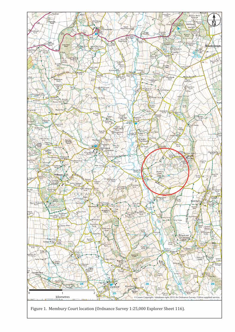
N
0 1 2kilometres © Crown Copyright / database right 2010. An Ordnance Survey / Edina supplied service.
Figure 1. Membury Court location (Ordnance Survey 1:25,000 Explorer Sheet 116).
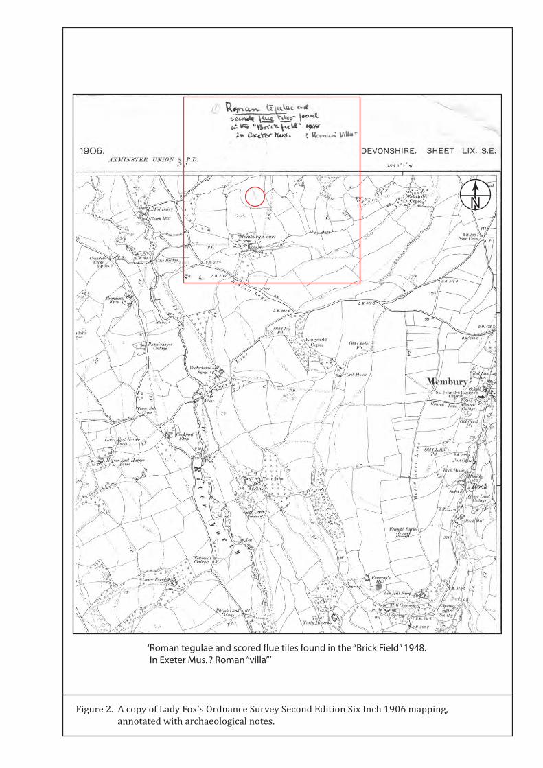
Figure 2. A copy of Lady Fox’s Ordnance Survey Second Edition Six Inch 1906 mapping, annotated with archaeological notes.
N
‘Roman tegulae and scored flue tiles found in the “Brick Field” 1948. In Exeter Mus. ? Roman “villa”’
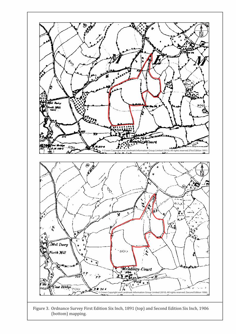
Figure 3. Ordnance Survey First Edition Six Inch, 1891 (top) and Second Edition Six Inch, 1906 (bottom) mapping.
© Crown Copyright and Landmark Information Group Limited (2010). All rights reserved. (First Edition 1891)
© Crown Copyright and Landmark Information Group Limited (2010). All rights reserved. (Second Edition 1906)
N
N
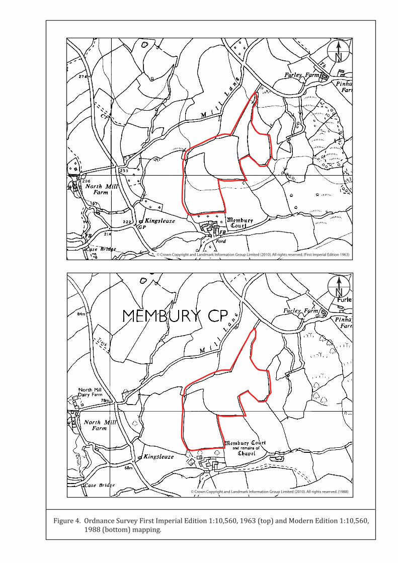
© Crown Copyright and Landmark Information Group Limited (2010). All rights reserved. (1988)
© Crown Copyright and Landmark Information Group Limited (2010). All rights reserved. (First Imperial Edition 1963)
N
N
Figure 4. Ordnance Survey First Imperial Edition 1:10,560, 1963 (top) and Modern Edition 1:10,560, 1988 (bottom) mapping.
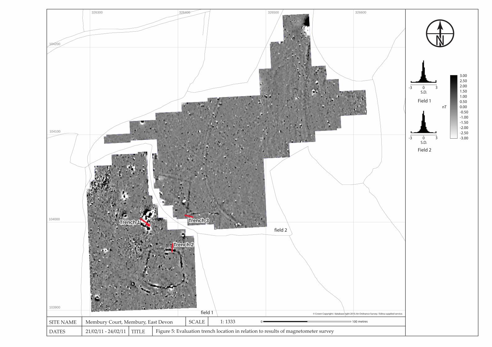
3.002.502.001.501.000.500.00-0.50-1.00-1.50-2.00-2.50-3.00
nT
-3 0 3S.D.
-3 0 3S.D.
Field 1
Field 2
Figure 5: Evaluation trench location in relation to results of magnetometer survey
SITE NAME
DATES TITLE
N
Membury Court, Membury, East Devon
21/02/11 - 24/02/11
0 100 metresSCALE 1: 1333
© Crown Copyright / database right 2010. An Ordnance Survey / Edina supplied service.field 1
field 2
326300 326400 326500 326600
103900
104000
104100
104200
Trench 1Trench 1
Trench 2Trench 2
Trench 3Trench 3
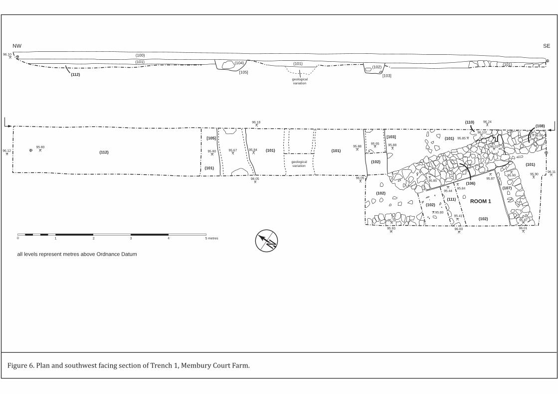
geological variation
96.1295.80
95.80 95.67 95.8495.88
95.65 95.88
95.85
96.24
96.1096.06
96.1195.9095.90
95.87
96.01
95.87
95.8495.44
95.41
96.00
95.80
95.78
95.93
96.0595.85
96.02
96.18
96.05
(102)
(101)
(108)
(101)
(102)
(102)
(102)
(106)
[103]
(101)(101)
(101)
[105]
(111)
(110)
(107)
ROOM 1
(112)
geological variation
(100)
(101) (104)
[105]
(101)(102)
[103]
(101)
(112)
96.10
NW SE
0 1 2 3 4 5 metres
all levels represent metres above Ordnance Datum
N
Figure 6. Plan and southwest facing section of Trench 1, Membury Court Farm.
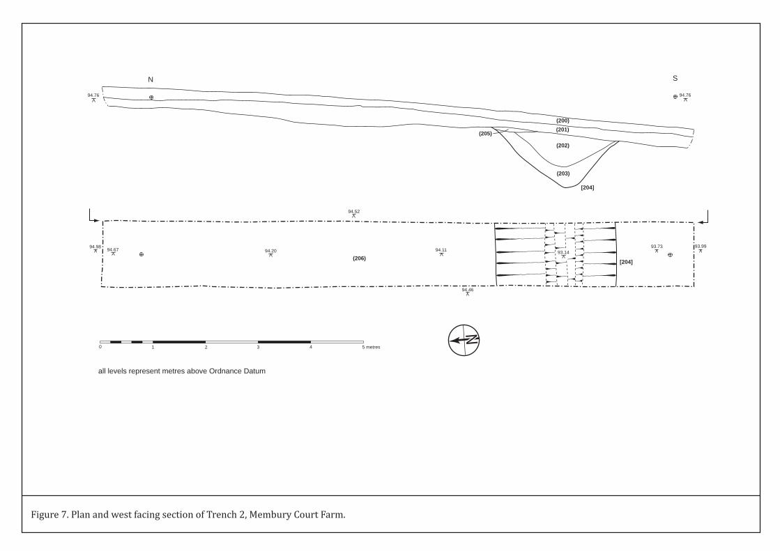
94.98 94.67 94.20
94.52
94.11
94.46
93.1493.73 93.99
[204](206)
(200)(201)
(202)
(203)
(205)
[204]
94.76 94.76
N S
0 1 2 3 4 5 metres
all levels represent metres above Ordnance Datum
N
Figure 7. Plan and west facing section of Trench 2, Membury Court Farm.
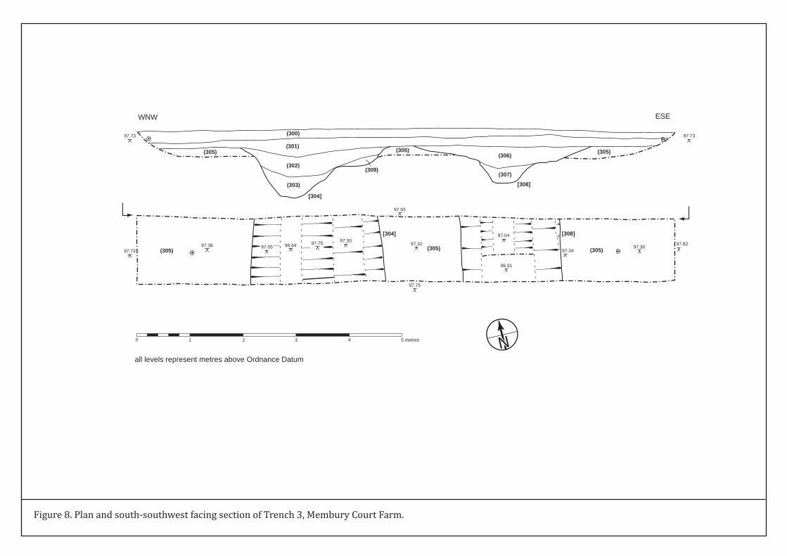
97.7397.38 97.05 96.64 97.75 97.30
97.32
97.93
97.75
97.04
96.91
97.3497.36
97.82(305) (305) (305)
[304] [308]
(305)
(300)
(301)
(302)
(303)
(305)(306)
(307)
[308]
(305)
[304]
(309)
WNW ESE
97.7397.73
0 1 2 3 4 5 metres
all levels represent metres above Ordnance Datum
N
Figure 8. Plan and south-southwest facing section of Trench 3, Membury Court Farm.
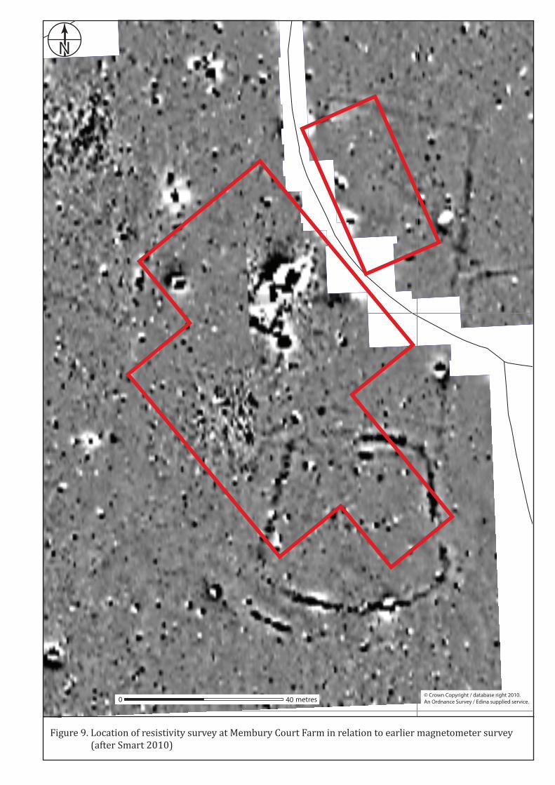
326400
103900
104000
N
0 40 metres© Crown Copyright / database right 2010. An Ordnance Survey / Edina supplied service.
Figure 9. Location of resistivity survey at Membury Court Farm in relation to earlier magnetometer survey (after Smart 2010)
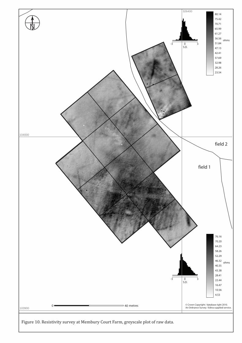
N
0 40 metres © Crown Copyright / database right 2010. An Ordnance Survey / Edina supplied service.
field 1
field 2
326400
103900
104000
76.16
70.20
64.23
58.26
52.29
46.32
40.35
43.38
28.41
22.44
16.47
10.56
4.53
ohms
0-3 3S.D.
Figure 10. Resistivity survey at Membury Court Farm, greyscale plot of raw data.
80.14
75.42
70.71
65.99
61.27
56.56
51.84
47.13
42.41
37.69
32.98
28.26
23.54
ohms0-3 3
S.D.

N
0 40 metres © Crown Copyright / database right 2010. An Ordnance Survey / Edina supplied service.
field 1
field 2
326400
103900
104000
75.43
69.57
63.71
57.84
51.98
46.12
40.26
34.40
28.54
22.68
16.82
10.96
5.10
ohms
0-3 3S.D.
Figure 11. Resistivity survey at Membury Court Farm, greyscale plot of processed data.
76.03
71.95
67.88
63.81
59.74
55.67
51.59
47.52
43.45
39.38
35.31
31.23
27.16
ohms0-3 3S.D.
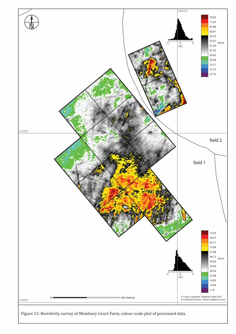
N
0 40 metres © Crown Copyright / database right 2010. An Ordnance Survey / Edina supplied service.
field 1
field 2
326400
103900
104000
75.43
69.57
63.71
57.84
51.98
46.12
40.26
34.40
28.54
22.68
16.82
10.96
5.10
ohms
0-3 3S.D.
Figure 12. Resistivity survey at Membury Court Farm, colour scale plot of processed data.
76.03
71.95
67.88
63.81
59.74
55.67
51.59
47.52
43.45
39.38
35.31
31.23
27.16
ohms0-3 3S.D.
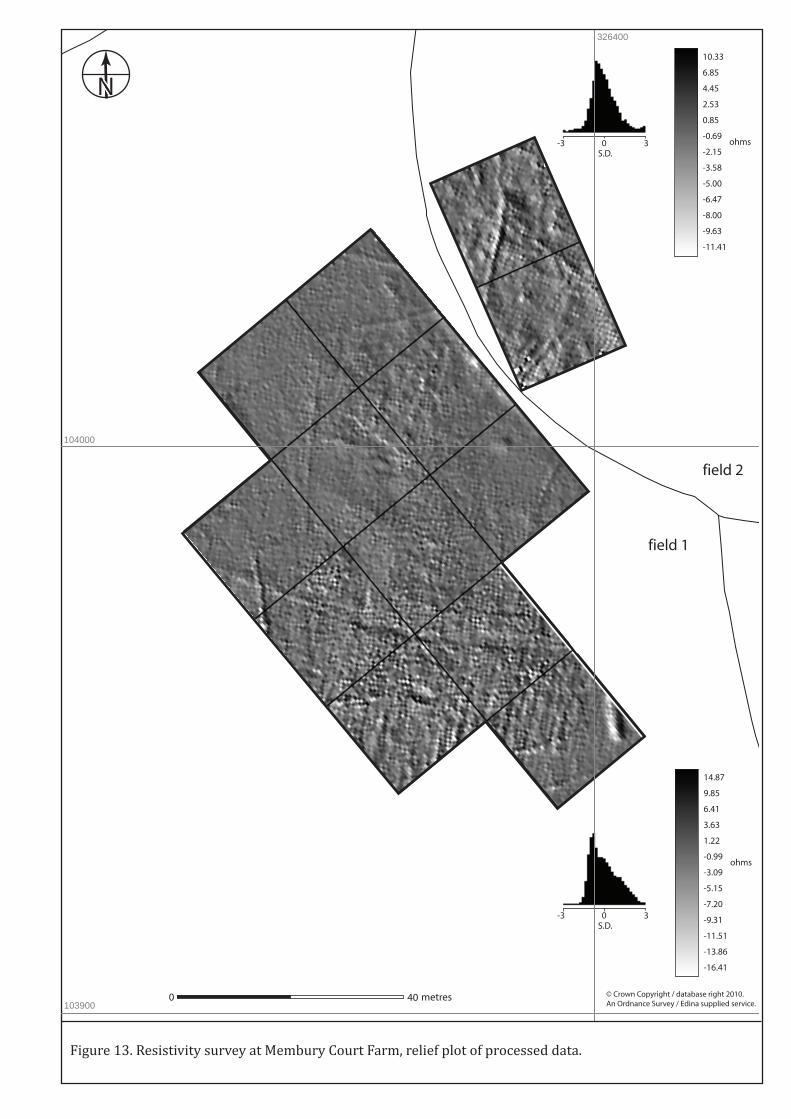
N
0 40 metres © Crown Copyright / database right 2010. An Ordnance Survey / Edina supplied service.
field 1
field 2
326400
103900
104000
14.87
9.85
6.41
3.63
1.22
-0.99
-3.09
-5.15
-7.20
-9.31
-11.51
-13.86
-16.41
ohms
0-3 3S.D.
Figure 13. Resistivity survey at Membury Court Farm, relief plot of processed data.
10.33
6.85
4.45
2.53
0.85
-0.69
-2.15
-3.58
-5.00
-6.47
-8.00
-9.63
-11.41
ohms0-3 3S.D.

N
0 40 metres © Crown Copyright / database right 2010. An Ordnance Survey / Edina supplied service.
field 1
field 2
326400
103900
104000
high resistance area, probable structural remains / debris
medium-high resistance area, possible structural remains / debris
high resistance linear, probable/certain wall line
high resistance linear, probable/certain stone-filled/waterlogged ditch and/or stone wall or bank
lower resistance linear, probable ditch
low resistance linear, probable ditch or drain
weak positive linear, probable cultivation mark
high resistance linear, possible wall line or cultivation mark
A
B
C
D
E
G
H
I
J
F
D
H
H
K
Figure 14. Resistivity survey at Membury Court Farm, interpretation plot of processed data.
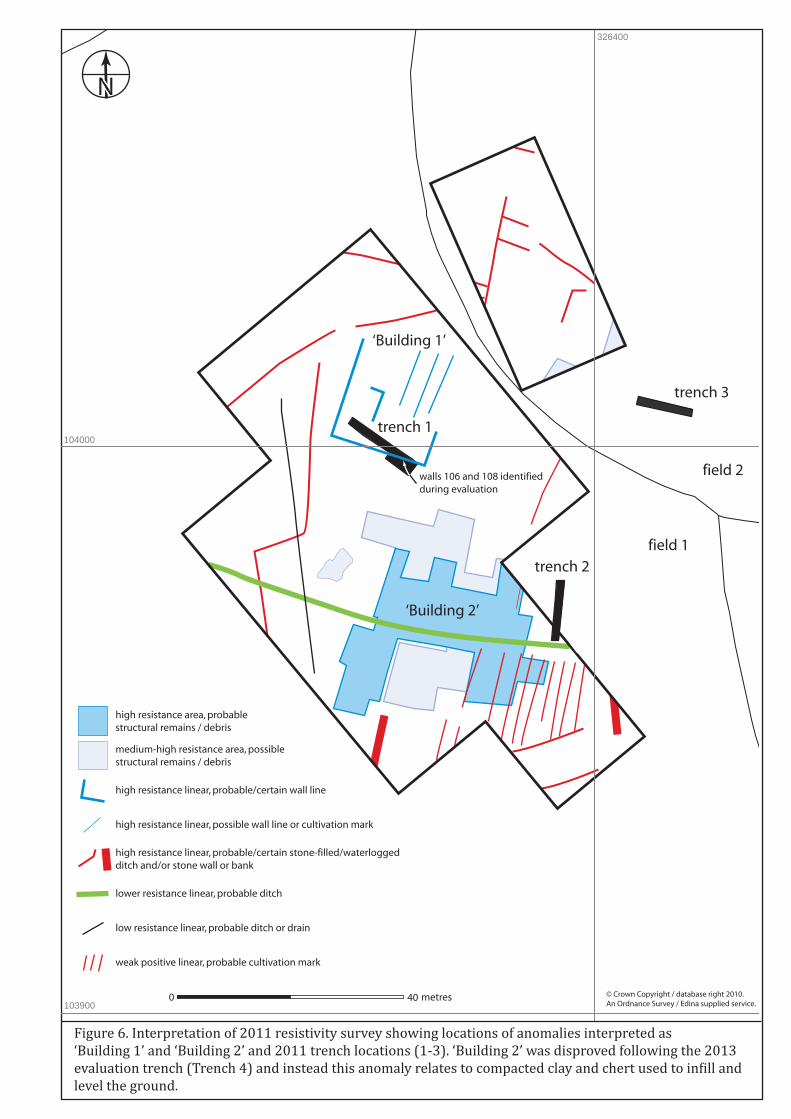
N
0 40 metres © Crown Copyright / database right 2010. An Ordnance Survey / Edina supplied service.
field 1
field 2
326400
103900
104000 Trench 1trench 1
trench 2
trench 3
walls 106 and 108 identified during evaluation
high resistance area, probable structural remains / debris
medium-high resistance area, possible structural remains / debris
high resistance linear, probable/certain wall line
high resistance linear, probable/certain stone-filled/waterlogged ditch and/or stone wall or bank
lower resistance linear, probable ditch
low resistance linear, probable ditch or drain
weak positive linear, probable cultivation mark
high resistance linear, possible wall line or cultivation mark
Figure 6. Interpretation of 2011 resistivity survey showing locations of anomalies interpreted as ‘Building 1’ and ‘Building 2’ and 2011 trench locations (1-3). ‘Building 2’ was disproved following the 2013evaluation trench (Trench 4) and instead this anomaly relates to compacted clay and chert used to in�ill andlevel the ground.
‘Building 1’
‘Building 2’
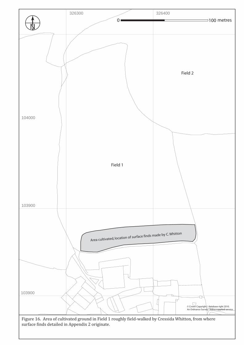
N
© Crown Copyright / database right 2010. An Ordnance Survey / Edina supplied service.
326300 326400
103900
104000
103900
0 100 metres
Area cultivated, location of surface finds made by C. Whitton
Field 1
Field 2
Figure 16. Area of cultivated ground in Field 1 roughly �ield-walked by Cressida Whitton, from where surface �inds detailed in Appendix 2 originate.
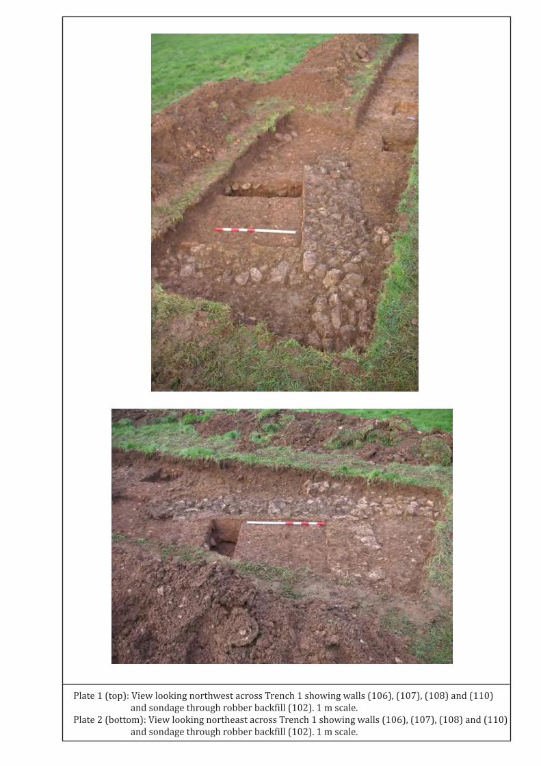
Plate 1 (top): View looking northwest across Trench 1 showing walls (106), (107), (108) and (110) and sondage through robber back�ill (102). 1 m scale.Plate 2 (bottom): View looking northeast across Trench 1 showing walls (106), (107), (108) and (110) and sondage through robber back�ill (102). 1 m scale.
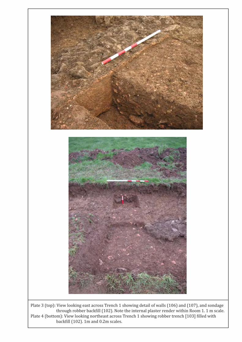
Plate 3 (top): View looking east across Trench 1 showing detail of walls (106) and (107), and sondage through robber back�ill (102). Note the internal plaster render within Room 1. 1 m scale.Plate 4 (bottom): View looking northeast across Trench 1 showing robber trench [103] �illed with back�ill (102). 1m and 0.2m scales.

Plate 5: Southwest-facing section of robber trench [105] in Trench 1. 1m and 0.2m scales.