arch. metall. mater. 65 (2020), 2, 529-538
TRANSCRIPT

BYBY NCNC
© 2020. The Author(s). This is an open-access article distributed under the terms of the Creative Commons Attribution-NonCom-mercial License (CC BY-NC 4.0, https://creativecommons.org/licenses/by-nc/4.0/deed.en which permits the use, redistribution of the material in any medium or format, transforming and building upon the material, provided that the article is properly cited, the use is noncommercial, and no modifications or adaptations are made.
Arch. Metall. Mater. 65 (2020), 2, 529-538
DOI: 10.24425/amm.2020.132790
P. OMRANIAN-MOHAMMADI1*, R. RAISZADEH1, H.R. SHAHVERDI2
HIGH TEMPERATURE CORROSION PERFORMANCE OF CARBON STEEL COATED WITH IRON ALUMINIDE IN MIXTURE OF O2 AND SO2 ATMOSPHERE
In this investigation the surface of an aluminized sample of plain carbon steel was melted and alloyed using a tingsten inert gas (TIG) welding process to produce iron-aluminide intermetallic phases on the surface. The produced coating was then character-ized by SEM and EDS and its high-temperature properties in O2 + 1%SO2 gas were examined. The results showed that the Fe3Al coating produced could protect the substrate as it was subjected to the corroding gases at 700oC due to the formation of an alumina layer between the substrate and an outer layer of Fe2O3. At 900oC, the coating could only protect the substrate for 64 h. The lack of further protection at this temperature is attributed to the decrease in the protective properties of alumina with an increase in its temperature and the lack of presence of enough Al atoms in the coating for the repair of the defects formed in the alumina layer.
Keywords: iron aluminide; high temperature corrosion; plain carbon steel
1 . Introduction
In many high temperature industrial applications, a resist-ance to high temperature corrosion is an important requirement. However, it is usually very difficult to develop steels that can satisfy this need [1]. Therefore, a great demand for new materials that have the capability to protect against such severe conditions exist, either as bulk or as overlays [2]. The iron aluminide phase Fe3Al is one of the best candidates to fulfil this need [1].
Interest in developing iron-aluminide alloys for high tem-perature applications has existed for several years, primarily due to their superior high temperature oxidation and sulfidation resistance [3-6]. These alloys are lower in cost and have better corrosion resistance compared to conventional Ni-based and stainless-steel alloys. This corrosion resistance has been attrib-uted to a strong adherent surface layer of aluminum oxide that is stable under a wide range of environments [5,6].
Iron aluminide has a low ductility which causes consid-erable technical difficulties in the fabrication of parts in bulk form [1,2,4]. The aforementioned property limits the industrial application of this material. Using iron aluminide as a coating instead of bulk is a logical alternative [1,2].
Iron aluminide coating is especially attractive for the power generation industry, where in most cases a work-piece is
exposed to both oxygen and sulfur. Sulfur is present in all fossil fuels and compounds containing sulfur are usually produced in most chemical and petrochemical processes and combustion atmospheres. Excess oxygen is usually injected into industrial furnaces to ensure the complete combustion of fuels. This excess oxygen reacts with the sulfur present in the fuel to produce SO2 and SO3 [7]. Sulfur found in zinc, copper and other metallic ores could cause problems in extractive processes [1,7].
Generally, there are two different approaches to produce iron-aluminide coatings: single-stage or double-stage methods. Single-stage methods are more commonly used and include direct deposition of FeAl or Fe3Al coatings through processes such as electro-spark deposition [8], chemical vapor deposition [9] and pack cementation [10]. The second approach is based on the generation of a primary surface layer and employing a subse-quent treatment in order to produce the iron-rich aluminide [2].
One surface treatment technique that has long been used for the surface modification of steels and other alloys is the melting of a pre-coated substrate by a thermal source such as an electrical arc or a laser. Sohi et al. [11] pre-placed ferrochro-mium powder with different thicknesses on a ductile iron and afterwards melted the surface of the alloy with the tungsten inert gas (TIG) process. They found that this treatment increased the hardness of the treated layer compared to that of the base metal.
1 SHAHID BAHONAR UNIVERSITY OF KERMAN, FACULTY OF ENGINEERING, DEPARTMENT OF METALLURGY AND MATERIALS SCIENCE, KERMAN, IRAN2 TARBIAT MODARES UNIVERSITY, FACULTY OF ENGINEERING, MATERIALS SCIENCE AND ENGINEERING DEPARTMENT, JALAL ALE AHMAD HIGHWAY, 14115-111 TEHRAN, IRAN
* Corresponding author: [email protected]
530
Buytoz and Ulutan [12] used the TIG surface alloying to coat the surface of an austenitic stainless-steel plate and studied the effects of the process parameters on the coating microstructure. Omranian et al. [13] also used the TIG process to form a layer of iron aluminide on an aluminized plain carbon steel plate. They found that the volume of the pool formed during the surface melting had a critical influence on the determination of the phases formed during the process. Similar studies were also carried out on ductile iron [14,15], low carbon steel [16], 8620 steel [17] and other alloys. In all of these aforementioned stud-ies, the produced coated layer was characterized by measuring various parameters such as hardness, wear resistance, chemical composition and microstructure.
In this investigation the surface of an aluminized plain car-bon steel was melted and alloyed using an inverter TIG welding machine to produce iron-aluminide intermetallic phases on the surface. The produced coating was then characterized by SEM and EDS and its high-temperature properties in O2 + 1%SO2 gas were examined.
2. Material and methods
The sheets used in this study were aluminized plain carbon steel with a thickness of 1.5 mm and a chemical composition of 0.15 wt% C, 0.6 wt% Mn and 0.1 wt% Si. The surface of the sheet was melted and alloyed using an inverter TIG welding machine (Pars-Digital PSQ 250 AC/DC) with an electrical current of 40A. This current was found [13] to be the optimum current at which a dense and hard Fe-rich iron aluminide (mainly Fe3Al) could be produced on the surface of the steel. The torch was stationary while a CNC table moved the substrate with a constant rate of 5 mm s–1 while an argon shield gas protected the arc. The torch scanned all the surface of the work piece in several parallel lines.
High temperature oxidation tests were carried out on iron aluminide coatings in O2 + 1%SO2 atmosphere. For this purpose, a tube furnace with a quartz reaction chamber was utilized. Iso-thermal oxidation tests were performed at 700 and 900°C for 4, 16, 64 and 100 h. The gas flow rate in these experiments was 100 mL min–1. The mass of the specimens before and after the oxidation was measured using a precision balance (Shimadzu) with an accuracy of 10–4 g, and the surface and cross-section of the samples were studied using a scanning electron microscope (SEM, JEOL JSM-6390) fitted with an energy dispersive X-ray spectroscope (EDS, Oxford Inca, Oxford Instruments) for microanalysis. The scales formed on the surface of the samples were also identified using a low angle X-ray diffraction (XRD) technique (grazing mode, scan rage 10o < 2θ < 90o, step size 0.039o, at 40 kV and 40 mA).
3. R esults
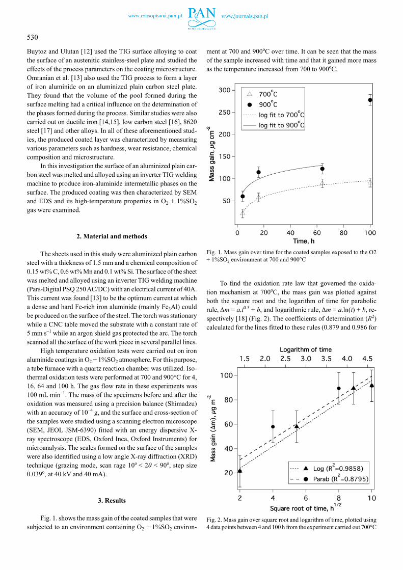
Fig. 1. shows the mass gain of the coated samples that were subjected to an environment containing O2 + 1%SO2 environ-
ment at 700 and 900oC over time. It can be seen that the mass of the sample increased with time and that it gained more mass as the temperature increased from 700 to 900oC.
Fig. 1. Mass gain over time for the coated samples exposed to the O2 + 1%SO2 environment at 700 and 900°C
To find the oxidation rate law that governed the oxida-tion mechanism at 700oC, the mass gain was plotted against both the square root and the logarithm of time for parabolic rule, Δm = a.t0.5 + b, and logarithmic rule, Δm = a.ln(t) + b, re-spectively [18] (Fig. 2). The coefficients of determination (R2) calculated for the lines fitted to these rules (0.879 and 0.986 for
Fig. 2. Mass gain over square root and logarithm of time, plotted using 4 data points between 4 and 100 h from the experiment carried out 700°C

531
the parabolic and logarithmic rules, respectively) determined the kinetics of the oxidation at 700oC to follow the logarithmic rule. The coefficients of the parabolic and logarithmic equations fitted to these data are shown in Table 1.
TABLE 1
Coeffi cients of the logarithmic equations fitted to the oxidation data
Temp, oC Experiment time, h
Logarithmic rule, Δm = a.ln (t) + b R2
Rate constant, a
Integral constant, b
700 4-100 22.4 7.2 0.986900 4-64 22.5 37.0 0.842
The mass gain data for the oxidation at 900oC also showed the same trend for 64 h (see Fig. 1). The mass gain, however, increased significantly when the sample was subjected to the cor-roding environment for 100 h. This sudden change in the kinetics of oxidation of the sample implied a change in the mechanism of oxidation after 64 h. Therefore, omitting the data for 100 h, the mass gain of the samples that were subjected to the corrod-ing environment at 900oC for 4 to 64 h were plotted against the square root and the logarithm of time (Fig. 3.) to assess the conformity of this data to the parabolic or logarithmic kinetic rate rules of oxidation. The coefficient of determination obtained for the logarithmic rule (R2 = 0.842) was higher than that of the parabolic rule (R2 = 0.682) and hence, the conformity of the kinetics of the oxidation to the logarithmic rule was confirmed.
Fig. 3. Mass gain over square root and logarithm of time, plotted us-ing 3 data points between 4 and 64 h from the experiment carried out at 900°C
Table 1 shows that the rate constant of the experiment car-ried out at 900oC was almost the same as that of the experiment
carried out at 700oC. The integral constant of the experiment at 900oC was, however, larger than that of the experiment at 700oC. These coefficients implied that although the oxidation rate at 900oC was higher than that of 700oC, but the required time needed for the rate of oxidation to decrease to a relatively low value was almost the same in these two temperatures. This behaviour is shown in Fig. 4., which shows the rate of mass gain of the samples over time. This figure also showed that the rate of mass gain decreased from high levels of 15 and 5 μg h–1 in the experiments carried out at 700 and 900oC, respec-tively, to low levels of 0.6 and 0.1 μg cm–2 h–1, respectively, in about 64 h.
Fig. 4. Rate of change in the mass gain by time for the two experiments carried out at 700 and 900°C
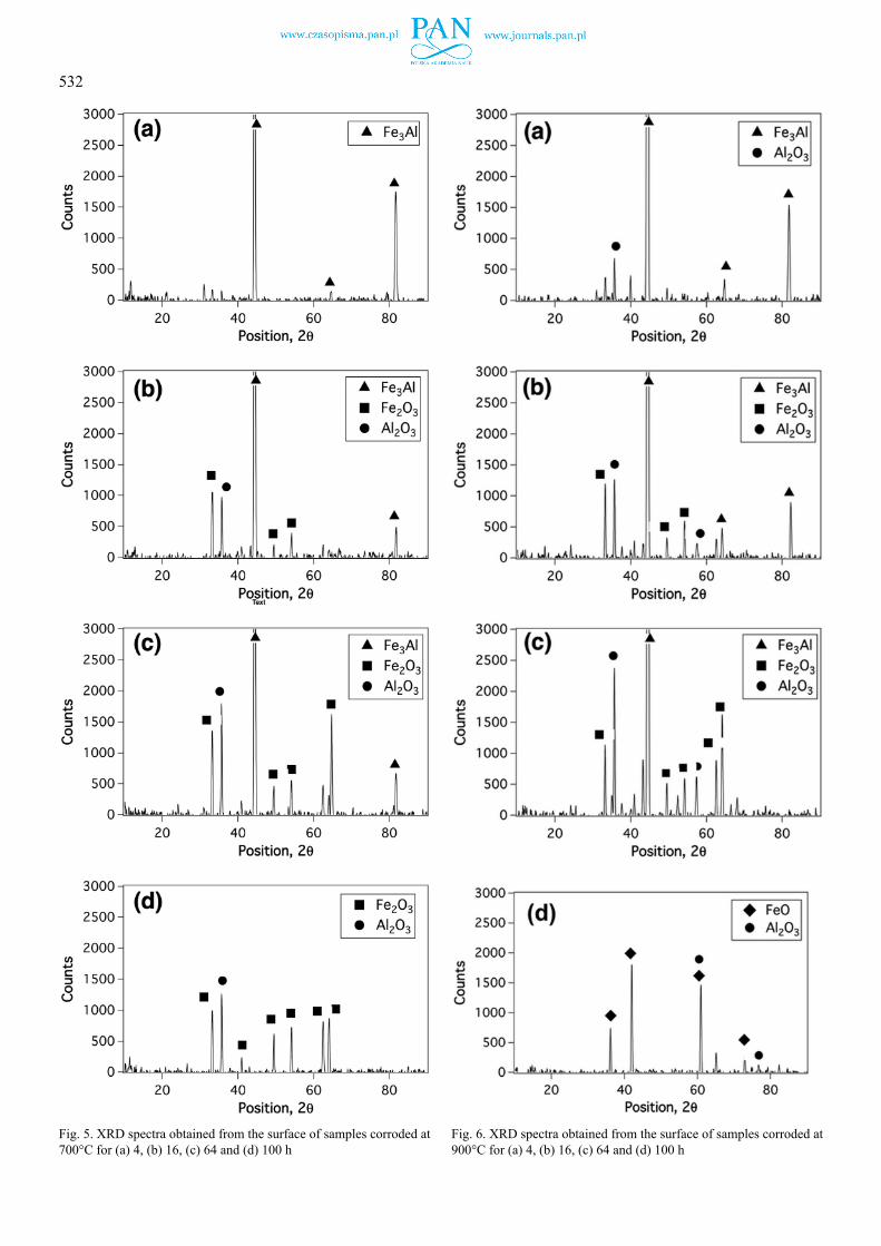
The phases formed on the surface of the samples during the corrosion reactions at 700 and 900oC are determined using the XRD spectra shown in Fig. 5 and Fig. 6, respectively. Fig. 5a shows that the only phase identified at 700oC and the oxida-tion time of 4 h was Fe3Al. The peaks associated with oxide phases were not present in this spectrum. As the oxidation time increased, the intensity of the peaks associated with the Fe3Al phase decreased and those associated with the Al2O3 and Fe2O3 increased (see Fig. 5b to Fig. 5c). The peaks associated with the Fe3Al phase were eliminated from the spectrum when the sample was subjected to the corrosive environment for 100 h (see Fig. 5d).
At 900oC and the reaction time of 4 h (Fig. 6a), again the main phase was Fe3Al. A peak associated with Al2O3 was also present in this reaction time but its intensity was low. The peaks associated with the oxide phases of Al2O3 and Fe2O3 increased in intensity as the reaction time increased (Fig. 6b and Fig. 6c). The main phases observed at 100 h reaction time in this temperature were FeO and Al2O3 (Fig. 6d).
532
Fig. 5. XRD spectra obtained from the surface of samples corroded at 700°C for (a) 4, (b) 16, (c) 64 and (d) 100 h
Fig. 6. XRD spectra obtained from the surface of samples corroded at 900°C for (a) 4, (b) 16, (c) 64 and (d) 100 h

533
Fig. 7 shows the SEM micrographs from the cross-section of the samples that were subjected to the corrosive environment at 700oC for different reaction times. The oxide layer formed on the samples consisted of two layers. These layers were not uniform in thickness and it is likely that some parts of the layers might have broken away during its preparation. Therefore, it was not possible to precisely measure the thickness of these layers. Fig. 8 shows the changes in composition of the cross-section of the specimen that was subjected to the corrosive environment at 700oC for 4 h, obtained by EDS. This figure shows that the outer and inner layers that formed on the specimen during the experiment were rich in Fe and Al, respectively, and hence were identified to be Fe2O3 (outer layer) and Al2O3 (inner layer).
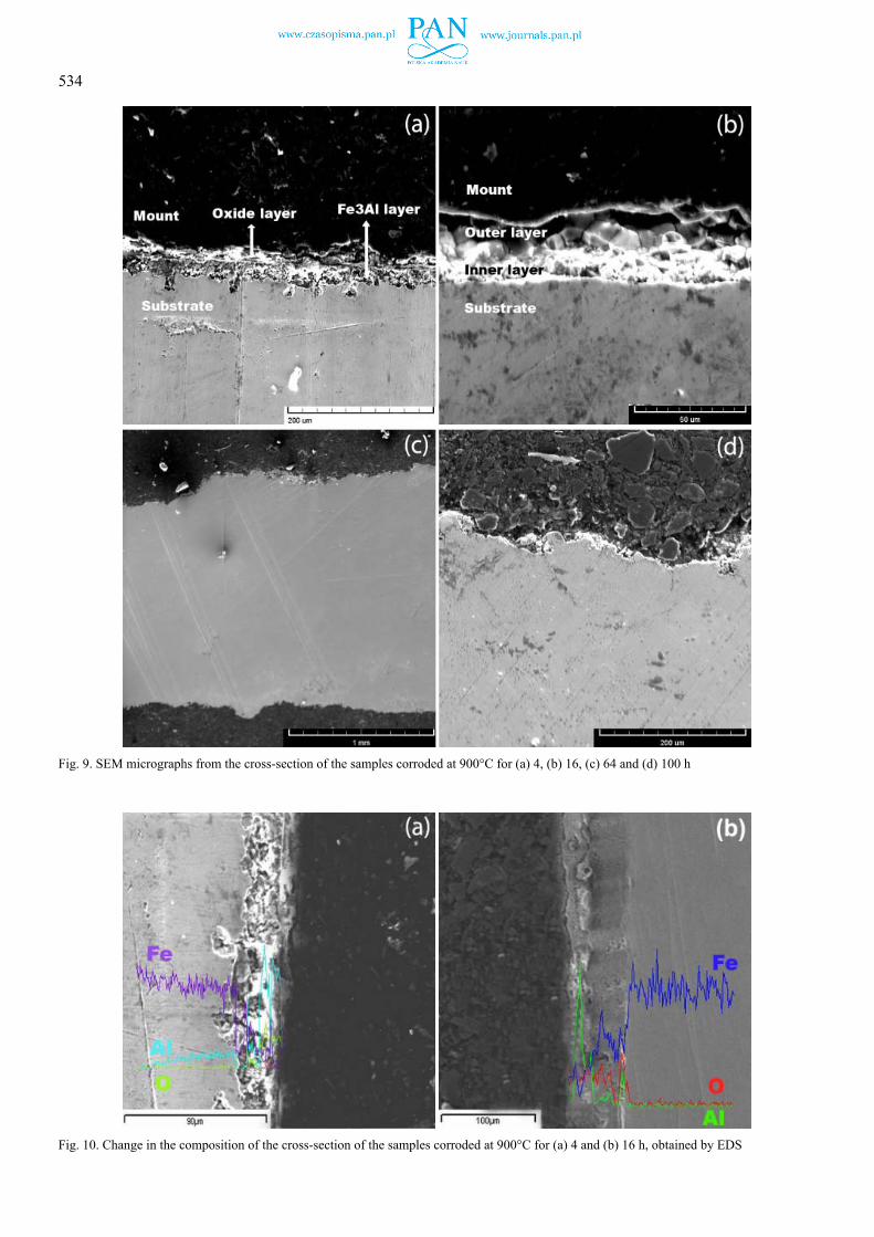
Fig. 9a and Fig. 9b show that at 900oC and the reaction time of 4 or 16 h, a double layer was observed on the substrate. No product layer could be seen on the substrate of the specimens that were subjected to the corrosive environment for 64 and 100 h (Fig. 9c and Fig. 9d, respectively). However, according to the corrosion mechanism explained in the discussion section of this
Fig. 7. SEM micrographs from the cross-section of the samples corroded at 700°C for (a) 4, (b) 16, (c) 64 and (d) 100 h
Fig. 8. Change in the composition at the cross-section of the samples corroded at 700°C for 4 h, obtained by EDS
534
Fig. 9. SEM micrographs from the cross-section of the samples corroded at 900°C for (a) 4, (b) 16, (c) 64 and (d) 100 h
Fig. 10. Change in the composition of the cross-section of the samples corroded at 900°C for (a) 4 and (b) 16 h, obtained by EDS

535
paper and also considering the work of other researchers [19-21], the presence of such layers on the substrates (which started to form at the reaction time of 16 h) were predictable. So, these layers might have spalled away during the sample preparation.
The change in the composition of the cross-section of the samples that were subjected to the corrosive environment at 900°C for 4 and 16 h is shown in Fig. 10a and Fig. 10b, respec-tively. After 4 h, a layer rich in Al and oxygen (i.e., Al2O3) formed on the Fe3Al coating. At 16 h, however, in contrast to 700oC, the outer and inner layers formed at 900oC after 16 h were identified to be Al2O3 (outer) and Fe2O3 (inner layer).
Fig. 11 shows the SEM micrographs from the surface of the specimens that were subjected to the O2 + 1%SO2 corrosive en-vironment at 700oC for different lengths of time. A darker phase and a lighter phase can be seen in all these micrographs. At the reaction time of 4 h (Fig. 11a) the lighter phase is dominant in the microstructure. The EDS study (Point 1 on Fig.11a.) revealed this phase to contain about 34 at% Fe and 65 at% O, i.e., an iron oxide. The EDS spectrum obtained from Point 2 also showed
the darker phase to be Al2O3 (about 28 at% Al and 70 at% O). At the longer reaction times of 16 to 100 h (Fig. 11b, Fig. 11c and Fig. 11d) the ratio of the darker to lighter phase gradually increased so that at a reaction time of 100 h (Fig. 11d), the darker phase dominated the microstructure. On the other hand, the concentration of Al in the lighter phase increased up to the reaction time of 64 h. This increase implied the growth of an alumina layer underneath the lighter phase (iron oxide layer).
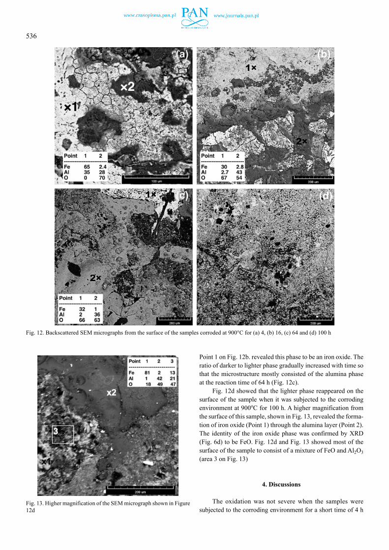
Fig. 12 shows the SEM micrographs obtained from the surface of the specimens that were subjected to the corrosive environment at 900oC for different lengths of time. The lighter phase observed at the reaction time of 4 h (Fig. 12a) consisted only of Fe and Al, i.e. probably Fe3Al phase (note the high concentration ratio of Fe to Al at Point 1 and the brittle nature of this phase on the figure). The EDS spectrum obtained from Point 2 on this figure revealed the darker phase to be alumina. At the reaction time of 16 h the nature of the lighter phase was completely altered relative to the reaction time of 4 h (no brittle cracks were observed) and the EDS spectrum obtained from
Fig. 11. Backscattered SEM micrographs from the surface of the samples corroded at 700°C for (a) 4, (b) 16, (c) 64 and (d) 100 h
536
Point 1 on Fig. 12b. revealed this phase to be an iron oxide. The ratio of darker to lighter phase gradually increased with time so that the microstructure mostly consisted of the alumina phase at the reaction time of 64 h (Fig. 12c).
Fig. 12d showed that the lighter phase reappeared on the surface of the sample when it was subjected to the corroding environment at 900oC for 100 h. A higher magnification from the surface of this sample, shown in Fig. 13, revealed the forma-tion of iron oxide (Point 1) through the alumina layer (Point 2). The identity of the iron oxide phase was confirmed by XRD (Fig. 6d) to be FeO. Fig. 12d and Fig. 13 showed most of the surface of the sample to consist of a mixture of FeO and Al2O3 (area 3 on Fig. 13)
4. Discussions
The oxidation was not severe when the samples were subjected to the corroding environment for a short time of 4 h
Fig. 12. Backscattered SEM micrographs from the surface of the samples corroded at 900°C for (a) 4, (b) 16, (c) 64 and (d) 100 h
Fig. 13. Higher magnification of the SEM micrograph shown in Figure 12d
537
(see Fig. 5a and Fig. 6a) and the dominant phase formed on the substrate was Fe3Al. The peaks associated with Al2O3 were not visible in the XRD spectrum obtained from the surface of the sample that was subjected to the corroding environment for 4 h even though the SEM obtained from this sample (Fig. 7a and Fig. 8) confirmed the presence of this oxide underneath the Fe3Al layer. The lack of these peaks in the XRD spectrum could be due to the inaccessibility of the X-ray beam to this layer, or its extreme thinness. The XRD results (Fig. 5 and Fig. 6) showed that the thickness of the Al2O3 and Fe2O3 layers increased and that of the Fe3Al layer decreased gradually as the reaction time in the corroding environment increased. This increase in the thickness of the oxide layers was associated with the increase in the mass of the samples, as is shown in Fig. 1.
Since the Gibbs free energy of formation of Fe2O3 is more negative than that of FeS (–742 and –100.4 kJ mol–1 [22], respec-tively), despite the presence of S in the corroding environment, no sulphides formed on the corroded samples. The higher affinity for oxygen compared to that of sulfur is true for most metals [23]. The tendency of Fe3Al to form Al2O3 at the presence of sulphur, even in low partial pressures of oxygen, is reported in the literature. However, Al2S3 is formed if the iron aluminide is subjected to pure SO2 [20].
Exposure of these samples to the corroding environment caused two oxides to form on the substrate. Fe2O3 and Al2O3. The Gibbs free energy of formation of Al2O3 is more negative than that of Fe2O3 (–1362 and –557 kJ mole–1 at 700oC (973 K), respectively [22]). Therefore, one might consider Al2O3 to grow with a higher rate and preferentially before Fe2O3 during the corrosion of these samples. The results obtained from this work (Fig. 11 and Fig. 12), however, revealed Fe2O3 to form predomi-nantly on the surface of the samples at relatively short reaction times. Such change in the preferencial formation of oxides was also observed by Bartar-Esfahani et al. [24] and Najafzadeh et al. [25] for the formation of Al2O3 at the presence of Sr and Mg, respectively, in the Al melt and Rao et al. [21] for the formation of Fe2O3 at the presence of Al in the Fe melt. The later research-ers attributed it to the low concentration of Al compared to Fe in the protective layer (in the present experiments measured to be 10 and 90 at% for Al and Fe, respectively [13]) which not only caused very few nucleation of Al2O3 but also the inability of the alloy to supply Al for the growth of the existing Al2O3 [26].
The results obtained in this study (Fig. 5, Fig. 6, Fig. 11 and Fig. 12) revealed that the Al2O3 layer expanded gradually and replaced the Fe2O3 layer. The oxygen needed for this ex-pansion would be provided either from the ambient atmosphere (through the Fe3Al or Fe2O3 layer), or from the reduction of the Fe2O3 phase by the Al atoms. Both paths would be feasible in this situation. On one hand, the Gibbs free energy of formation of Al2O3 is more negative than that of Fe2O3, and on the other hand, the Pilling-Bedworth ratio (PBR) of Fe2O3 is 2.14 [27], which implies that the oxide would chip off during the oxidation and cannot provide a good protection for the layers underneath.
The Pillin g-Bedworth ratio (PBR) of Al2O3 is 1.28 [28] and hence it is a dense and protective layer. Therefore, its for-
mation underneath the Fe2O3 layer (see Fig. 8) caused the alloy to be relatively protected against further oxidation and changed the severe parabolic oxidation of the plain carbon steel [29] to a logarithmic trend, as is shown by Fig. 1 to Fig. 3. According to Fig. 1, this protection increased by time throughout the ex-periment carried out at 700oC and the formed Al2O3 layer could protect the alloy for at least 100 h.
The coefficient of diffusion of Al in Fe3Al was about 85 times higher at 900oC compared to 700oC [30]. Therefore, at 900oC, both the thermodynamics and the kinetics of the reactions were in favour of the formation of Al2O3 and this oxide formed as the outer layer on the substrate ( see Fig. 10). The formation of this layer provided a rapid protection against the corroding environment and, as is shown in Fig. 4, the decrease in the rate of mass gain happened with a steeper gradient and the rate of mass gain at 64 h was lower compared to that of 700oC.
However, the sample that was subjected to the corroding environment at 900oC was protected by the alumina layer only for (at least) 64 h. The corroded sample showed a significant mass gain of more than 2 folds between the experiment times of 64 and 100 h. Fig. 12d and Fig. 13 revealed the formation of FeO phase through the Al2O3 layer. The formation of this phase implied that at this stage almost all of the Al in the Fe3Al phase had been converted to Al2O3 and hence no more Al was available for the formation of the alumina phase. Sleppy [31] demonstrated that the protective property of the Al2O3 layer gradually decreased as its temperature increased above 700oC. At 900oC, the rate of formation of defects in the alumina layer was relatively high [31] and oxygen could pass through these defects to react with the Fe atoms underneath to form FeO. The Pilling-Bedworth ratio of FeO is 1.7 [28] and hence the forma-tion of this phase was accompanied by an expansion in volume which caused the newly-formed phase to perforate through the Al2O3 layer.
In summary, at 700oC, the alumina layer could protect the surface of the sample against the corroding environment since the rate of formation of defects in the produced alumina layer was low enough to decrease the penetration of oxygen to the substrate. However, due to a high rate of formation of defects in the alumina layer, this protection was not enough when the sample was subjected to the corroding environment at 900oC.
5. Conclu sions
Fe3Al coating was successfully produced on a substrate of aluminized plain carbon steel by melting the aluminized sur-face layer using a TIG welding machine. The high-temperature properties of the produced coating in an atmosphere containing O2 + 1%SO2 was then characterised. The following results were obtained.
1. At 700oC, the Fe3Al coating transferred to an outer layer of Fe2O3 and an inner layer of Al2O3. The alumina layer produced between the substrate and the Fe2O3 layer provided the alloy with a relatively good protection against further oxidation.

538
2. The kinetics of oxidation of the coated samples followed a logarithmic rule at 700oC, which confirmed the protective nature of the coating of the substrate.
3. At 900oC, the Fe3Al coating again transferred to Fe2O3 and Al2O3 but the arrangement of the layers on the substrate was in a reverse order compared to the layers formed at 700oC, i.e. the outer layer was Al2O3 and the inner one was Fe2O3. This difference is attributed to the higher diffusion rate of Al in the Fe3Al phase which made the relatively fast diffusion of this ele-ment towards the surface of the layer possible.
4. The kinetics of oxidation of the coated sample followed a logarithmic rule at 900oC up to 64 h. The rate of oxidation suddenly increased when the sample was subjected to the cor-roding atmosphere for 100 h. This sudden increase in the rate of oxidation is attributed to the increase in the rate of formation of defects in the alumina layer at this temperature and the lack of presence of further Al atoms in the coating for the repair of these defects.
REFERENCES
[1] P. Fan, E. Riddle, Z.Z. Fang, H.Y. Sohn, Surf. Coat. Technol. 202, 6090-6094 (2008).
[2] M. Emami, H.R. Shahverdi, S. Hayashi, M.J. Torkamany, Metall. Mater. Trans. A 44, 3176-3184 (2013).
[3] W.J. Cheng, C.J. Wang, Mater. Charact. 69, 63-70 (2012).[4] S.F. Corbin, E. Toyserkani, A. Khajepour, Mater. Sci. Eng. A 354,
48-57 (2003).[5] Y. Zhang, B.A. Pint, G.W. Garner, K.M. Cooley, J.A. Haynes,
Surface and Coatings Technology, 188-189, 35-40 (2004).[6] Y. Zhang, B.A. Pint, K.M. Cooley, J.A. Haynes, Surf. Coat. Tech-
nol. 200, 1231-1235 (2005).[7] M. Emami, S.M.M Hadavi, S. Hayashi, H.R. Shahverdi, Oxid.
Met. 80, 437-451(2013).[8] N.I. Jamnapara, S. Frangini, J. Alphonsa, N.L. Chauhan,
S. Mukherjee, Surf. Coat. Technol. 266, 146-150 (2015).
[9] C. Christoglou, N. Voudouris, G.N. Angelopoulos, Surf. Coat. Technol. 155, 51-58 (2002).
[10] Y.Q. Wang, Y. Zhang, D.A. Wilson, Surf. Coat. Technol. 204, 2737-2744 (2010).
[11] M.H. Sohi, M. Ebrahimi, H.M. Ghasemi, A. Shahripour, Appl. Surf. Sci. 258, 7348-7353 (2012).
[12] S. Buytoz, M. Ulutan, Surf. Coat. Technol. 200, 3698-3704 (2006).[13] P. Omranian Mohammadi, R. Raiszadeh, H. Shahverdi, Int. J. Adv.
Manuf. Technol. 96, 1655-1663 (2018).[14] A. Amirsadeghi, M.H. Sohi, J. Mater. Process. Technol. 201, 673-
677 (2008).[15] A. Amirsadeghi, M.H. Sohi, S.F. Bozorg, J. Iron. Steel Res. Int.
15, 86-94 (2008).[16] M. Eroğlu, N. Özdemir, Surf. Coat. Technol. 154, 209-217 (2002).[17] O.N. Çelik, M. Ulutan, H. Gaşan, Ü. Er, S. Buytoz, Surf. Coat.
Technol. 206, 1423-1429 (2011).[18] A.S. Khanna, Introduction to high temperature oxidation and
corrosion, 2002 ASM International.[19] P. Kofstad, R. Bredesen, Solid State Ionics. 52, 69-75 (1992).[20] W.H. Lee, R.Y. Lin, Mater. Chem. Phys. 58, 231-242 (1999).[21] V.S. Rao, R.G. Baligidad, V.S. Raja, Intermetallics. 10, 73-84 (2002).[22] W.F. Gale, T.C. Totemeier, Smithells metals reference book, 2003
Elsevier.[23] V.S. Rao, V. Raja, Intermetallics. 11, 119-128 (2003).[24] H. Bartar Esfahani, R. Raiszadeh, H. Doostmohammadi, Metall.
Mater. Trans. A 47, 1331-1338 (2016).[25] F. Najafzadeh-Bakhtiarani, R. Raiszadeh. J. Mater. Sci. 46, 1305-
1315 (2010).[26] R. Raiszadeh, W.D. Griffiths, Metall. Mater. Trans. B 42, 133-143
(2011).[27] O. Milton, Engineering Materials Science, 1995 San Diego:
Academic Press.[28] N.B. Pilling, R.E. Bedsworth, J. Inst. Met. 29, 529-591(1923).[29] R.Y. Chen, W.Y.D. Yeun, Oxid. Met. 59, 433-468 (2003).[30] L. Yajiang, W. Juan, Y. Yansheng, M. Haijun, Bull. Mater. Sci. 28,
69-74 (2005).[31] W.C. Sleppy, J. Electrochem. Soc. 108, 1097-1102 (1961).