arch bridges - introductionchicagobridgeproject.weebly.com/uploads/1/0/4/9/104944195/bridge...arch...
TRANSCRIPT
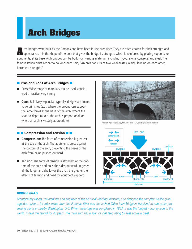
Arch Bridges
BRIDGE BRAG
Montgomery Meigs, the architect and engineer of the National Building Museum, also designed the complex Washingtonaqueduct system. It carries water from the Potomac River over the arched Cabin John Bridge in Maryland to two water pro-cessing plants in nearby Washington, D.C. When the bridge was completed in 1863, it was the longest masonry arch in theworld. It held the record for 40 years. The main arch has a span of 220 feet, rising 57 feet above a creek.
■ Pros and Cons of Arch Bridges ■
■ Pros: Wide range of materials can be used; consid-ered attractive; very strong
■ Cons: Relatively expensive; typically, designs are limitedto certain sites (e.g., where the ground can supportthe large forces at the base of the arch; where thespan-to-depth ratio of the arch is proportional; orwhere an arch is visually appropriate)
■ ■ Compression and Tension ■ ■
■ Compression: The force of compression is greatestat the top of the arch. The abutments press againstthe bottom of the arch, preventing the bases of thearch from being pushed outward.
■ Tension: The force of tension is strongest at the bot-tom of the arch and pulls the sides outward. In gener-al, the larger and shallower the arch, the greater theeffects of tension and need for abutment support.
A rch bridges were built by the Romans and have been in use ever since. They are often chosen for their strength andappearance. It is the shape of the arch that gives the bridge its strength, which is reinforced by placing supports, or
abutments, at its base. Arch bridges can be built from various materials, including wood, stone, concrete, and steel. Thefamous Italian artist Leonardo da Vinci once said, “An arch consists of two weaknesses, which, leaning on each other,become a strength.”
Antietam Aqueduct, Savage, MD, completed 1834, courtesy Lawrence Biemiller
30 Bridge Basics | © 2005 National Building Museum
live load
span span
distance
keystonekeystone
abutments abutmentabutment
compression
tensionroadway

© 2005 National Building Museum | Bridge Essentials 29
Walter B. Jones Bridge, Hyde County, NC, completed 1981, courtesy North Carolina Department of Traffic
roadway
live load
pier
beam
distance
compression
tension
pierpier
spanspan
Beam Bridges
■ Pros and Cons of Beam Bridges ■
■ Pros: Easy to build; inexpensive relative to otherbridge types; used widely in urban and rural settings
■ Cons: Limited span; large ships or heavy boat trafficcannot pass underneath; design generally not consid-ered very interesting or eye-catching
■ ■ Compression and Tension ■ ■
■ Compression: As live loads, such as cars and trucks,travel across the bridge, the force of compressionacts on the top of the roadway and passes downinto the piers.
■ Tension: The force of tension acts on the undersideof the roadway, which is pulled apart by the live loadspressing down on the top of the roadway.
B eam bridges are the oldest known bridges and tend to be the simplest to design and build. Roughly half of all bridgesin the United States are beam bridges. They consist of vertical piers and horizontal beams. A beam bridge’s strength
depends on the strength of the roadway and can be increased by adding additional piers. While beam bridges can be quitelong, the span, or distance between adjacent piers, is usually small.
BRIDGE BRAG
It’s the loooooooonnnnnnngest bridge in the world, and it’s a beam bridge! The Lake Pontchartrain Causeway in Louisiana isapproximately 24 miles long, and its twin spans are supported by more than 9,000 pilings.

© 2005 National Building Museum | Bridge Essentials 33
Cable-Stayed Bridges
■ Pros and Cons of Cable-Stayed Bridges ■
■ Pros: Span medium distances (500–2,800 feet); lessexpensive and faster to build than suspension bridges;considered attractive
■ Cons: Typically more expensive than other types ofbridges, except suspension bridges
■ ■ Compression and Tension ■ ■
■ Compression: As traffic pushes down on the road-way, the cables, to which the roadway is attached,transfer the load to the towers, putting them in com-pression.
■ Tension: The force of tension is constantly acting onthe cables, which are stretched because they areattached to the roadway.
T he first modern cable-stayed bridge was completed in Sweden in 1956. Cable-stayed bridges were created as aneconomical way to span long distances. This bridge’s design and success were made possible as new materials and
construction techniques were developed. Cable-stayed bridges have one or more towers, each of which anchors a set ofcables attached to the roadway.
compression
tension
live load
pylon
distance
roadway
cables
spanspan
live load
BRIDGE BRAG
America’s longest cable-stayed bridge, the Cooper River Bridge in Charleston, South Carolina, opened in summer 2005. It isapproximately 2.5 miles long and 186 feet above the river. The central span between the two towers is 1,546 feet, and thetowers themselves rise 575 feet above the water line.
Fred Hartman Bridge, Baytown/Laporte, TX, completed 1995, courtesy Kevin Stillman, Texas Depart-ment of Transportation

Suspension Bridges
BRIDGE BRAG
The Tacoma Narrows suspension bridge in Washington State was known as “Galloping Gertie” because it rippled like a rollercoaster. Completed in July 1940, the first heavy storm four months later caused the bridge to break and collapse from wind-induced vibrations. It was replaced by a stiffer bridge, which has proven to be satisfactory.
■ Pros and Cons of Suspension Bridges ■
■ Pros: Span distances up to 7,000 feet; consideredattractive; allow large ships and heavy boat traffic topass underneath
■ Cons: Expensive (require a long time and a largeamount of material to build)
■ ■ Compression and Tension ■ ■
■ Compression: Traffic pushes down on the roadway,but because it is suspended from the cables, theweight is carried by the cables, which transfer theforce of compression to the two towers.
■ Tension: The force of tension is constantly acting onthe cables, which are stretched because the roadwayis suspended from them.
S uspension bridges are strong and can span long distances. One early bridge was designed and built in 1801 in Penn-sylvania. They are expensive because they take a long time to build and require a large amount of material. They are
commonly found across harbors with a lot of boat traffic. The primary elements of a suspension bridge are a pair of maincables stretching over two towers and attached at each end to an anchor. Smaller cables attached to the main cables supportthe roadway.
Golden Gate Bridge, San Francisco, CA, completed 1937, used with permission from The GoldenGate Bridge, Highway and Transportation District, San Francisco, CA, www.goldengatebridge.org
32 Bridge Basics | © 2005 National Building Museum
live load
roadway
cables
anchor
tower
cables
towercompression
tension
anchor
span
distance

© 2005 National Building Museum | Bridge Essentials 31
Truss Bridges
■ Pros and Cons of Truss Bridges ■
■ Pros: Very strong; frequently used as a draw bridge oras an overpass for railroad trains
■ Cons: Difficult to construct; high maintenance; difficultto widen if necessary; generally not considered attractive
■ ■ Compression and Tension ■ ■
■ Compression: As traffic pushes down on the road-way, compression acts on the upper horizontal mem-bers of the truss structure.
■ Tension: Tension acts on the bottom horizontal mem-bers of the truss structure. The forces of tension andcompression are shared among the angled members.
W ooden truss bridges were used as early as the 1500s, but the first metal one was completed in 1841. They are verystrong and have been used for railroad bridges mainly because of the heavy loads that they can support. A truss, a
rigid support structure that is made up of interlocking triangles, holds up the roadbed and is set between two piers. The tri-angle is used because it is the only shape that is inherently rigid.
George Street Bridge, Aurora, IN, completed 1887, courtesy Indiana Department of Transportation
live loadcompression
tension
pier pier
distance
roadway
trusses
span
BRIDGE BRAG
It’s difficult to see the trusses on some of America’s best-known truss bridges, the covered bridges that were common in therural Northeast. The roofs were not constructed to protect people from severe weather, but to preserve the truss systemitself. Wooden bridges without roofs would last 10 to 15 years, but covering the bridge extended its life to 70 or 80 years.

Arch BridgesArch Bridges
Bridge Basics Program Kit | © 2005 National Building Museum
Natchez Trace Parkway Arches
Engineer Conde McCullough
Location: Gold Beach, ORCompleted: 1932Spans: 230 ft.
Engineer HNTB Corporation
Location: Nashville, TNCompleted: 2004Span: 545 ft.
Engineer unknown
Location: Savage, MDCompleted: 1834Spans: 40 ft.
Gateway Boulevard Bridge
Rogue River Bridge Antietam Aqueduct
Courtesy of FIGG Courtesy of HNTB/Mark McCabe, 2005
Courtesy of Oregon Department of Transportation Courtesy of Lawrence Biemiller
Engineer FIGG
Location: near Nashville, TNCompleted: 1994Spans: 580 ft.

Beam BridgesBeam Bridges
Bridge Basics Program Kit | © 2005 National Building Museum
Engineer FIGG
Location: Glenwood Canyon, COCompleted: 1993Spans: 300 ft.
Hanging Lake Viaduct
Engineer FIGG
Location: San Antonio, TXCompleted: 1989Spans: 100 ft.
Engineer unknown
Location: Yellowstone, WYCompleted: 1932Spans: ranging 16–34 ft.
Engineer unknown
Location: Hyde County, NCCompleted: 1981Spans: ranging 70–120 ft.
Seven Mile River Bridge
San Antonio �“Y” Bridges Walter B. Jones Bridge
Courtesy of FIGG Courtesy of National Park Service
Courtesy of FIGG Courtesy of North Carolina Department of Traffic
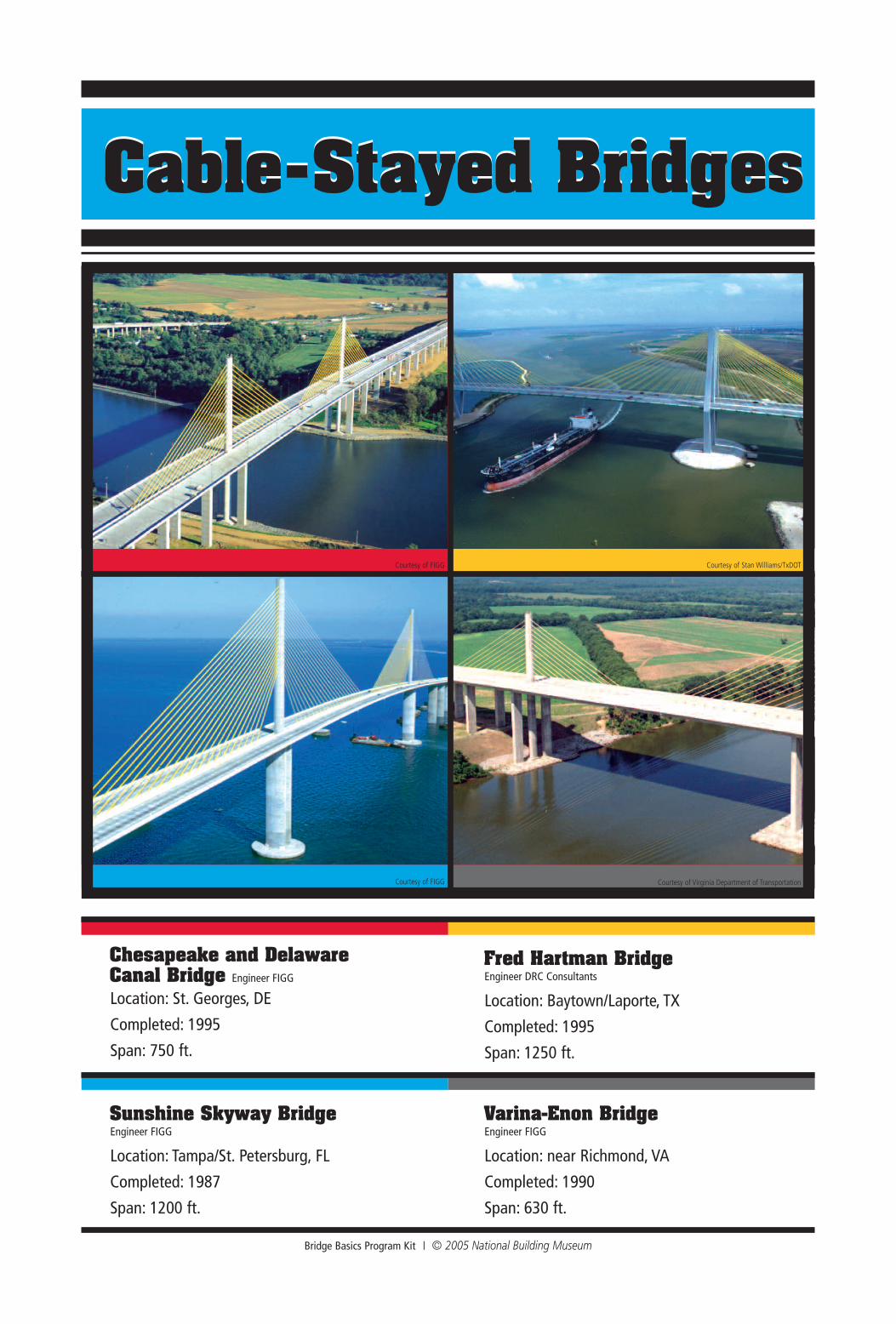
Cable-Stayed BridgesCable-Stayed Bridges
Bridge Basics Program Kit | © 2005 National Building Museum
Location: St. Georges, DECompleted: 1995Span: 750 ft.
Chesapeake and Delaware Canal Bridge Engineer FIGG
Engineer FIGG
Location: Tampa/St. Petersburg, FLCompleted: 1987Span: 1200 ft.
Engineer DRC Consultants
Location: Baytown/Laporte, TXCompleted: 1995Span: 1250 ft.
Engineer FIGG
Location: near Richmond, VACompleted: 1990Span: 630 ft.
Fred Hartman Bridge
Sunshine Skyway Bridge Varina-Enon Bridge
Courtesy of FIGG Courtesy of Stan Williams/TxDOT
Courtesy of FIGG Courtesy of Virginia Department of Transportation
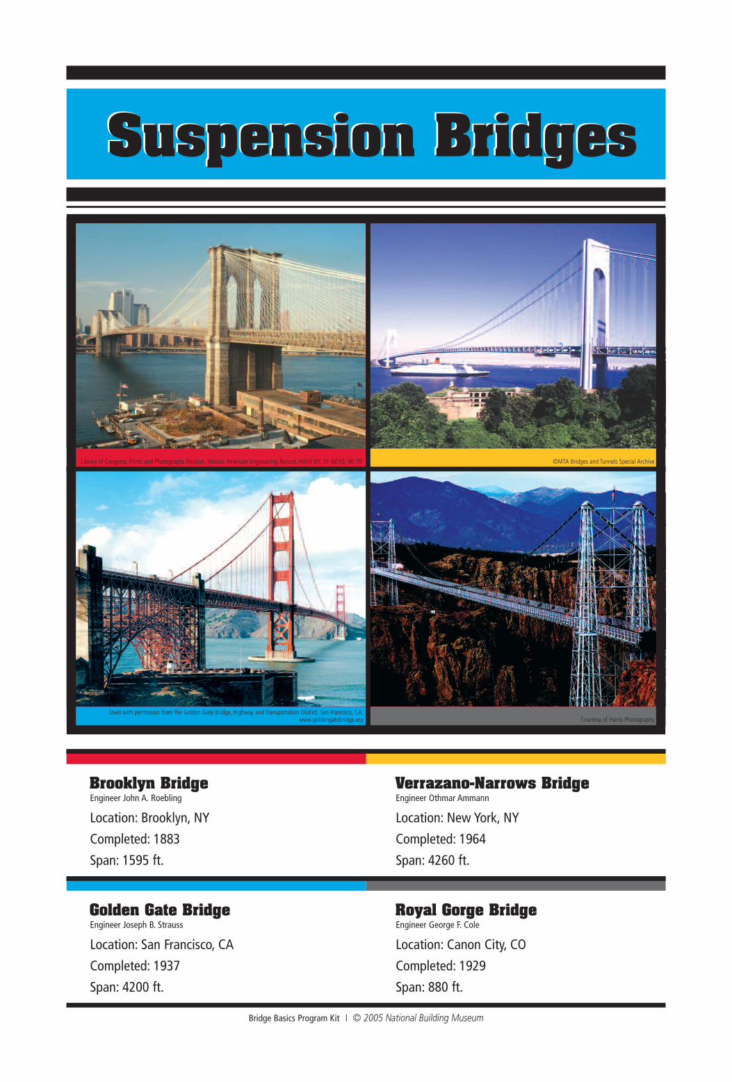
Suspension BridgesSuspension Bridges
Bridge Basics Program Kit | © 2005 National Building Museum
Engineer John A. Roebling
Location: Brooklyn, NYCompleted: 1883Span: 1595 ft.
Brooklyn Bridge
Engineer Joseph B. Strauss
Location: San Francisco, CACompleted: 1937Span: 4200 ft.
Engineer Othmar Ammann
Location: New York, NYCompleted: 1964Span: 4260 ft.
Engineer George F. Cole
Location: Canon City, COCompleted: 1929Span: 880 ft.
Verrazano-Narrows Bridge
Golden Gate Bridge Royal Gorge Bridge
©MTA Bridges and Tunnels Special Archive
Courtesy of Harris PhotographyUsed with permission from The Golden Gate Bridge, Highway and Transportation District, San Francisco, CA,
www.goldengatebridge.org
Library of Congress, Prints and Photographs Division, Historic American Engineering Record, HAER NY, 31-NEYO, 90-79
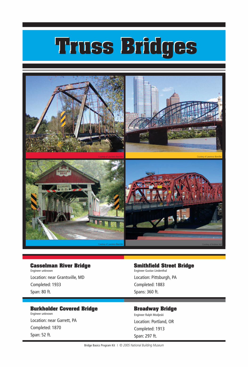
Truss BridgesTruss Bridges
Bridge Basics Program Kit | © 2005 National Building Museum
Engineer unknown
Location: near Grantsville, MDCompleted: 1933Span: 80 ft.
Casselman River Bridge
Engineer unknown
Location: near Garrett, PACompleted: 1870Span: 52 ft.
Engineer Gustav Lindenthal
Location: Pittsburgh, PACompleted: 1883Spans: 360 ft.
Engineer Ralph Modjeski
Location: Portland, ORCompleted: 1913Span: 297 ft.
Smithfield Street Bridge
Burkholder Covered Bridge Broadway Bridge
Courtesy of Lawrence Biemiller Courtesy of Lawrence Biemiller
Courtesy of Lawrence Biemiller Courtesy of Andrew Hall