arcadius ®xp c spinal system...arcadiusxp c spinal system acdf device. as with any procedure, it is...
TRANSCRIPT

Arcadius®XP C Spinal SystemStand-Alone Anterior Cervical Discectomy and Fusion (ACDF) Interbody Device Surgical Technique
Aesculap Spine

2
Arcadius®XP C Spinal SystemStand-Alone Anterior Cervical Discectomy and Fusion (ACDF) Interbody Device Surgical Technique
Table of Contents:
I. System Overview . . . . . . . . . . . . . . . . . . . . . . . . . . . . . . . . . . . . . . . . . . . . . . . . 3
II. Indications and Contraindications . . . . . . . . . . . . . . . . . . . . . . . . . . . . . . . . . . 4
III. Warnings and Precautions . . . . . . . . . . . . . . . . . . . . . . . . . . . . . . . . . . . . . . . 4-5
IV. Surgical Technique . . . . . . . . . . . . . . . . . . . . . . . . . . . . . . . . . . . . . . . . . . . . 6-17
a. Patient Positioning and Exposure . . . . . . . . . . . . . . . . . . . . . . . . . . . . . . 6
b. Preparation . . . . . . . . . . . . . . . . . . . . . . . . . . . . . . . . . . . . . . . . . . . . . . . . 7
c. Implant Sizing . . . . . . . . . . . . . . . . . . . . . . . . . . . . . . . . . . . . . . . . . . . 7-8
d. Implant Preparation and Insertion . . . . . . . . . . . . . . . . . . . . . . . . . . 9-13
e. Screw Preparation and Insertion . . . . . . . . . . . . . . . . . . . . . . . . . . 14-16
f. Implant Removal (if necessary) . . . . . . . . . . . . . . . . . . . . . . . . . . . . . . . 17
g. Verification of Final Implant Placement . . . . . . . . . . . . . . . . . . . . . . . . 17
h. Appendix . . . . . . . . . . . . . . . . . . . . . . . . . . . . . . . . . . . . . . . . . . . . . . . . . 17
V. Implant Information . . . . . . . . . . . . . . . . . . . . . . . . . . . . . . . . . . . . . . . . . . 18-20
a. Implant Bone Screw and Construct Information . . . . . . . . . . . . . . 18-19
b. Locking Mechanism Information . . . . . . . . . . . . . . . . . . . . . . . . . . . . . 20
VI. Implant Overview . . . . . . . . . . . . . . . . . . . . . . . . . . . . . . . . . . . . . . . . . . . . . . . 21
VII. Instrument Overview . . . . . . . . . . . . . . . . . . . . . . . . . . . . . . . . . . . . . . . . . 22-27
VIII. Tray Overview . . . . . . . . . . . . . . . . . . . . . . . . . . . . . . . . . . . . . . . . . . . . . . . 28-30

3
System Features: ■ Wide variety of implant options ■ Generous graft window ■ Surface texturing ■ Two X-ray marker pins in the cage ■ Midline accessibility for screw insertion ■ Diverging screw design ■ Dual locking mechanism ■ Self-tapping bone screws ■ Comprehensive array of instrumentation
Design Advantages: ■ Optimized implant fit – Implants are available in a variety of options to meet the requirements of
varying patient anatomies. — Implant footprints: 13 mm x 16 mm, 15 mm x 17 mm — Heights: 5 mm, 6 mm, 7 mm, 8 mm, 9 mm, 10 mm and 11 mm — Lordotic angles: 4°, 7° ■ Unique implant design – Requires no additional supplementary fixation system when used with the
supplied bone screws. ■ Comprehensive array of instrumentation – Intuitively designed to accommodate steep angles and
provide ease in screw insertion. ■ Bone screws are self-tapping. — Screws are 4 mm in diameter and offered in 14 mm, 16 mm and 18 mm lengths. ■ Simple and secure locking mechanism – Implant contains an integrated dual locking mechanism with
single-step activation. ■ Maximized stability – Provided by optimized implant fit, large graft window, surface texturing and
two diverging bone screws. ■ Excellent imaging properties – Plasmapore®XP surface enhancing technology and X-ray marker pins
allow for improved visibility during imaging. ■ Zero-profile – Intrinsic design does not add profile to the anterior border of the vertebral body,
limiting risk of damage to adjacent soft tissue and blood vessels.
I. System Overview

4
Arcadius®XP C Spinal SystemStand-Alone Anterior Cervical Discectomy and Fusion (ACDF) Interbody Device Surgical Technique
Indications for Use:The ArcadiusXP C Spinal System is intended to be used as an intervertebral body fusion device as a stand-alone system used with the supplied bone screws and requires no additional supplementary fixation. It is intended for spinal fusion procedures at one level in the cervical spine from the C2-C3 disc space to the C7-T1 disc space for the treatment of cervical degenerative disc disease (defined as discogenic pain with degeneration of the disc confirmed by history and radiographic studies) using autograft bone. Patients should be skeletally mature and must have undergone a regimen of at least six (6) weeks of nonoperative treatment prior to being treated with the ArcadiusXP C Spinal System.
ContraindicationsAny medical or surgical condition that could preclude the potential success of the implantation. These include: ■ Existing or risk of acute or chronic infections, fever/leukocytosis ■ Progressive joint disease or bone absorption syndromes such as Paget’s disease, osteopenia,
osteoporosis or osteomyelitis which may prevent adequate fixation. ■ Severe defects of the bony structures of the spine which are a prerequisite for stable implantation of
the cages. ■ Bone tumors in the region of the implant anchoring ■ Proven or suspected allergy/foreign body reactions to implant materials ■ Conditions that may place excessive stresses on bone and implants, such as severe obesity, pregnancy
or degenerative diseases. The decision to use this system in such conditions must be made by the physician, taking into account the risks versus the benefits to the patient.
■ Patients resistant to following postoperative restrictions on movement, especially in athletic and occupational activities
■ Systemic, metabolic and degenerative diseases ■ Psychosocial problems; unwillingness or inability of the patient to follow the instructions for
postoperative treatment ■ Drug abuse or alcoholism ■ Generally poor condition of the patient ■ Prior fusion at the level(s) to be treated ■ All cases that are not listed under “Indications”
WARNINGS ■ Implants supplied in sterile condition must not be resterilized or reused under any circumstances.
Danger to the patient and possible loss of implant functionality may result from resterilization.
■ Increased risk of migration is possible due to over-preparation of the vertebral body endplates. When preparing the implant bed, make certain that the base and cover plates of the adjacent vertebral bodies are not weakened.
■ The coated surfaces of the ArcadiusXP C Spinal System cage may be damaged by improper handling. Avoid direct contact with the coated surfaces. Handle implants carefully.
■ Risk of insufficient stability or implant failure is possible due to using fewer than the two internal screw fixations provided. Apply both screws or use an additional supplemental spinal fixation system that has been cleared for use in the cervical spine, such as cervical plating systems.
■ Excessive insertion forces may cause damage to the implant.
II. Indications for Use and Contraindications
III. Warnings and Precautions

5
WARNINGS (continued) ■ Backing out and loosening of the bone screw can occur when the screw is not fully inserted into the
cage. Insert the bone screw until it is fully engaged.
■ Potential risks identified with the use of this intervertebral body fusion device, which may require additional surgery, include: device component fracture, loss of fixation, pseudoarthrosis (i.e., non-union) fracture of the vertebra, neurological injury and vascular or visceral injury.
■ Inaccurate markings of the midline may result in incorrect position of the implant. Always mark the midline under X-ray visualization. Determine the center of the vertebral disc using a midline marker under X-ray visualization.
CAUTION ■ Based upon dynamic testing results, physicians should consider the levels of implantation, patient
weight, patient activity level, other patient conditions, etc., which may impact the performance of the Arcadius®XP C Spinal System.
■ Avoid using high frequency and/or electrocautery surgical devices in proximity to the implant to avoid damage to the ArcadiusXP C Spinal System cages. Remove and replace the implant if the implant is damaged.
PRECAUTIONS ■ The implantation of the intervertebral body fusion device should be performed only by experienced
spinal surgeons with specific training in the use of this device because this is a technically demanding procedure presenting a risk of serious injury to the patient.
■ Avoid mixing unalloyed titanium, titanium alloy, stainless steel and other cobalt alloy implants for implants that are in contact with each other.
■ Components of the ArcadiusXP C Spinal System should not be used with components of any other system or manufacturer.
MRI SAFETY INFORMATION The ArcadiusXP C Spinal System has not been evaluated for safety and compatibility in the MR environment. It has not been tested for heating, migration or image artifact in the MR environment. The safety of the ArcadiusXP C Spinal System in the MR environment is unknown. Scanning a patient who has this device may result in patient injury.
Please refer to product insert for complete system description, indications and warnings.
III. Warnings and Precautions (continued)

6
Arcadius®XP C Spinal SystemStand-Alone Anterior Cervical Discectomy and Fusion (ACDF) Interbody Device Surgical Technique
a. Patient Positioning and Exposure
1. Anterior access will be required for insertion of the ArcadiusXP C Spinal System ACDF device. As with any procedure, it is important to understand the lordotic angle of disc spaces and the surrounding anatomy in order to plan for anterior surgery. Preoperative radiographs should be taken to measure disc heights and required implant range. Patient positioning and exposure of the anterior cervical spine are performed in accordance with the standard anterior cervical surgical technique:
■ Place the patient in the supine position. ■ Utilize the standard anterior approach to the cervical
spine. (Fig. 1)
■ Provide the level of exposure to the implantation site the surgeon deems necessary to perform the surgery. A cervical retraction system, such as Aesculap’s Caspar™ Cervical Retractor System, can be used to provide adequate visualization to the front of the cervical spine. (Fig. 2)
Fig. 1 Fig. 2
IV. Surgical Technique

7
IV. Surgical Technique (continued)
Fig. 3 Fig. 4 Fig. 5
b. Preparation
1. Prepare the intervertebral space by utilizing the anterior discectomy instruments the surgeon feels are necessary to properly prepare the disc space and vertebral endplates.
■ A cervical distraction system, such as Aesculap’s Caspar™ Cervical Distraction System, can be used to gradually achieve the desired working height.
■ Perform a thorough discectomy. (Fig. 3) ■ Ensure adequate neural decompression has been
established. ■ Prepare the endplates to receive the Arcadius®XP C
Spinal System implant.
Note: Excessive removal of the endplates may weaken the construct and cause subsidence of the implant.
c. Implant Sizing
1. Proper implant size can be established using the trial spacers while the interspace is distracted. Trial implants are available in two footprint sizes, two lordotic angles and seven heights. Each trial implant is color-coded by implant height and labeled with the corresponding footprint, height and lordotic angle.
2. Select an appropriately-sized trial implant based on patient anatomy and preoperative radiographic analysis. (Table 1 on page 8)
3. Utilize the cottle mallet to gently advance the trial into the disc space.
4. Manipulate the trial implant as needed to attain the desired position. (Fig. 4)
5. Continue to evaluate trial implants until a tight fit is achieved.
6. Assess the final implant fit and position with intraoperative AP and lateral fluoroscopy.
7. Once the appropriate size and height of the implant has been determined, select the corresponding color-coded rasp. The rasp is used to roughen and expose the end plates and prepare them for the placement of the corresponding sized implant. (Fig. 5)
Note: A properly chosen implant will ensure disc height is maintained and implant migration is minimized.

8
Arcadius®XP C Spinal SystemStand-Alone Anterior Cervical Discectomy and Fusion (ACDF) Interbody Device Surgical Technique
IV. Surgical Technique (continued)
Rasp/Trial Color Code (Table 1)
Trial Part No. Rasp Part No. Lordosis Footprint Height Color
ME126R US039R 4° 13x16 5 mm
YellowME133R US139R 7° 13x16 5 mm
ME142R US058R 4° 15x17 5 mm
ME232R US214R 7° 15x17 5 mm
ME127R US044R 4° 13x16 6 mm
BlueME134R US198R 7° 13x16 6 mm
ME143R US059R 4° 15x17 6 mm
ME233R US217R 7° 15x17 6 mm
ME128R US054R 4° 13x16 7 mm
RedME135R US199R 7° 13x16 7 mm
ME144R US068R 4° 15x17 7 mm
ME234R US218R 7° 15x17 7 mm
ME129R US055R 4° 13x16 8 mm
GreenME136R US211R 7° 13x16 8 mm
ME145R US069R 4° 15x17 8 mm
ME235R US219R 7° 15x17 8 mm
ME130R US056R 4° 13x16 9 mm
WhiteME137R US212R 7° 13x16 9 mm
ME146R US093R 4° 15x17 9 mm
ME236R US220R 7° 15x17 9 mm
ME131R US057R 4° 13x16 10 mm
GreyME138R US213R 7° 13x16 10 mm
ME147R US099R 4° 15x17 10 mm
ME237R US222R 7° 15x17 10 mm
ME132R N/A 4° 13x16 11 mm
BlackME139R N/A 7° 13x16 11 mm
ME148R N/A 4° 15x17 11 mm
ME238R N/A 7° 15x17 11 mm

9
IV. Surgical Technique (continued)
Fig. 6 Fig. 7 Fig. 8 Fig. 9
d. Implant Preparation and Insertion
1. Select the implant that corresponds to the final trial implant size evaluated.
2. Implant Preparation ■ Assemble the All-in-One guide or universal inserter
to the multi-tool handle. (Fig. 6) ■ All-in-One guide should be selected to correspond to
the height of the chosen implant. (Table 2 on page 10)
■ Attach and secure the selected ArcadiusXP C Spinal System implant to the distal end of the insertion instrument. (Fig. 7)
■ Attach and secure the selected implant to the distal end of the insertion instrument by turning the proximal knob in a clockwise direction. (Fig. 8)
■ Fill the implant with autograft material by utilizing the packing block and tamp. (Fig. 9)
■ Place the implant into the corresponding footprint space of the packing block.
■ Fill the implant with autograft material, and use the tamp to firmly pack autograft material into the implant.
■ To determine the volume of the grafts window, please see table below.
Note: The insertion instrument consists of an All-in-One Guide with a safety stop or, alternatively, an inserter without a safety stop. It is recommended that the safety stop be utilized to ensure the implant is seated flush against the anterior border of the vertebral body.
Note: The dimensions of the trial implants are designed to match the Arcadius®XP C Spinal System implants (footprint, height and lordotic angle).
Item No.
Graft Volume in cm3
SO726P 0.24SO727P 0.30SO728P 0.35SO729P 0.40SO730P 0.46SO731P 0.51SO732P 0.56SO706P 0.27SO707P 0.32SO708P 0.37
Item No.
Graft Volume in cm3
SO709P 0.43SO710P 0.48SO711P 0.53SO712P 0.59SO766P 0.32SO767P 0.39SO768P 0.46SO769P 0.53SO770P 0.60SO771P 0.67
Item No.
Graft Volume in cm3
SO772P 0.74SO746P 0.35SO747P 0.42SO748P 0.49SO749P 0.56SO750P 0.63SO751P 0.71SO752P 0.78

10
Arcadius®XP C Spinal SystemStand-Alone Anterior Cervical Discectomy and Fusion (ACDF) Interbody Device Surgical Technique
IV. Surgical Technique (continued)
Options for Inserter (both used with ME075R) (Table 2)
Item No. Description Height Color
ME063R Interbody Insertion Instrument Universal N/A
ME064R All-in-One Guides for Interbody 5 mm Yellow
ME065R All-in-One Guides for Interbody 6 mm Blue
ME066R All-in-One Guides for Interbody 7 mm Red
ME067R All-in-One Guides for Interbody 8 mm Green
ME068R All-in-One Guides for Interbody 9 mm White
ME069R All-in-One Guides for Interbody 10 mm Grey
ME070R All-in-One Guides for Interbody 11 mm Black
Warning: Incorrect selection of the All-in-One Guide will result in implant damage and malfunction of the locking mechanism during the pilot hole preparation and bone screw insertion surgical steps. Confirm that the selected All-in-One Guide corresponds to the selected ArcadiusXP C implant.
Note: The All-in-One Guides are color coded to match the height of the corresponding implant (5 mm - yellow, 6 mm - blue, 7 mm - red, 8 mm - green, 9 mm - natural, 10 mm - gray and 11 mm - black).

11
IV. Surgical Technique (continued)
4. Verification of Implant Placement ■ Obtain AP fluoroscopic images to confirm midline
placement of the device. ■ Obtain lateral fluoroscopic images to confirm the
anterior edge of the implant is seated flush with the anterior border of the vertebral body.
■ Observe the X-ray markers in both the AP and lateral views to ensure that the implant is not rotated within the disc space.
■ Manipulate the implant as needed by gently tapping the impactor with the mallet.
■ Relax the Caspar™ Distractor.
■ Check whether the implant is stable and securely positioned.
Note: It is recommended to confirm implant position prior to removing the insertion instrument.
Note: Relaxing the Caspar Distractor places the implant in compression. This allows the grooves on the superior and inferior surfaces of the Arcadius®XP C Spinal System implant to come in contact with the vertebral body endplates, thereby producing a more secure fit within the intervertebral disc space.
3. Implant Insertion ■ Introduce the implant into the disc space. The
implant should be inserted centrally in AP. (Fig. 10)
Caution: It is important to consider the midline and neutral alignment while implanting this device to avoid placing neural elements at risk.
Note: If using an All-in-One Guide with the safety stop, a positive stop at the end of the insertion sleeve ensures that the graft is positioned flush with the anterior border of the vertebral body and helps prevent over insertion and spinal canal compromise.
Fig. 10

12
Arcadius®XP C Spinal SystemStand-Alone Anterior Cervical Discectomy and Fusion (ACDF) Interbody Device Surgical Technique
■ Obtain additional AP and lateral fluoroscopic images to document midline placement and neutral alignment.
■ The final AP and lateral images should reflect neutral alignment of the ArcadiusXP C Spinal System implant.
5. Once satisfied with the implant location and fit, remove the insertion instrument.
IV. Surgical Technique (continued)
Caution: If the implant can be moved slightly in the intervertebral space, there is a risk of dislocation, and the implant should be replaced with the next largest size in height.
Note: The ArcadiusXP C Spinal System implant requires no additional supplementary fixation system when used with the two supplied bone screws.

13
Soft Tissue Protection Sleeve ME103 Assembly:
The Soft Tissue Protection Sleeve is a single-use, disposable sleeve that is used to protect surrounding anatomy from the U-joint mechanism.
The Soft Tissue Protection Sleeve can be assembled to the following instruments: U-Joint Screwdriver (ME055R), U-Joint Bone Awl (ME060R), U-Joint Drill (ME058R) and U-Joint Screw Extraction Instrument (ME072R).
■ Obtain additional AP and lateral fluoroscopic images to document midline placement and neutral alignment.
■ Prior to assembling the Soft Tissue Protection Sleeve, remove the spring covering the U-joint from the distal end of the shaft
■ Slide the sleeve 1 over the distal end until hard stop. (Figs.11 and 12)
■ The sleeve 1 can be removed by applying force in the opposite assembly direction.
IV. Surgical Technique (continued)
Note: The single use soft tissue protection sleeve does not ship standard with the Arcadius®XP C Instrument Set (ST0652), but can be ordered separately from Customer Service.
Fig. 11 - Assembling ME103 (U-Joint Screwdriver is shown)
Fig. 12 - Correct sleeve position (U-Joint Screwdriver is shown)
Hard Stop
Caution: Soft Tissue Protection Sleeve must be sitting flush up against the hard stop of the U-joint instruments. Soft Tissue Protection Sleeve must be checked via a visual inspection before use to make sure it is appropriately assembled. Excessive bending of the sleeve can cause fatigue or failure. The Soft Tissue Protection Sleeve is designed for a single use application. Upon completion of the case, the Soft Tissue Protection Sleeve should be removed and disposed.
1
1

14
Arcadius®XP C Spinal SystemStand-Alone Anterior Cervical Discectomy and Fusion (ACDF) Interbody Device Surgical Technique
IV. Surgical Technique (continued)
e. Screw Preparation and Insertion
1. For ease of bone screw insertion, it is recommended that a pilot hole is created at the intended screw placement site. A variety of instruments are available to meet surgeon preference for screw hole preparation and screw insertion. (Tables 3 and 4 on page 15) The ArcadiusXP C Spinal System is intended to be used with two bone screws.
■ Bone screws are available in three lengths: 14 mm, 16 mm and 18 mm (Table 5 on page 16)
Note: All screwdrivers are self-retaining. It is important to consider patient anatomy at the surgical level and implant footprint size, height and lordotic angle when selecting the proper screw length. Analysis of lateral screw length is essential to avoid screw contact with adjacent neural elements.
Caution: A mallet must not be used to advance the awl especially for 5 mm and 6 mm implants. The awl must be pushed/advanced by hand only.
Note: It is recommended to prepare screw holes and insert screws using X-ray guidance.

15
IV. Surgical Technique (continued)
Options for Bone Awl (Table 3)Item No. Description
ME060R U-Joint Bone Awl
ME061R Fixed Angle Bone Awl
ME062R Straight Bone Awl
ME402R Ball Joint Awl
Options for Drill (Table 4)Item No. Description
ME058R U-Joint Drill
ME059R Fixed Angle Drill
ME403R Ball Joint Drill Drill
Note: When using the All-in-One guide, the awl/drill cannot progress past the posterior border of the implant. When using the universal inserter, the awl/drill can progress 1 mm past the posterior border.
Warning: Risk of damaging biological structures (spinal cord, spinal nerve roots, ligaments, soft tissues, etc.) and the Arcadius®XP C implant if the drills and bone awls are used without the All-in-One Guide. ■ It is recommended to use the drills and bone awls with the All-in-One Guide.
Warning: Risk of damage to the ArcadiusXP C implant in the course of incorrectly advancing the bone awls and drills. ■ Do not apply an excessive compressive/hammering/bending/tilting/levering force to the bone awls and the drills. ■ Keep the instrument's tip directly aligned with the hole axis of the All-in-One Guide or the hole axis of the ArcadiusXP C implant. ■ The bone awls and the drills must be pushed/advanced by hand only.
16
Arcadius®XP C Spinal SystemStand-Alone Anterior Cervical Discectomy and Fusion (ACDF) Interbody Device Surgical Technique
e. Screw Preparation and Insertion (continued)
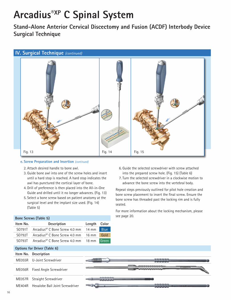
2. Attach desired handle to bone awl. 3. Guide bone awl into one of the screw holes and insert
until a hard stop is reached. A hard stop indicates the awl has punctured the cortical layer of bone.
4. Drill of preference is then placed into the All-in-One Guide and drilled until it no longer advances. (Fig. 13)
5. Select a bone screw based on patient anatomy at the surgical level and the implant size used. (Fig. 14) (Table 5)
Fig. 13 Fig. 14 Fig. 15
IV. Surgical Technique (continued)
Bone Screws (Table 5)Item No. Description Length ColorSO791T ArcadiusXP C Bone Screw 4.0 mm 14 mm BlueSO792T ArcadiusXP C Bone Screw 4.0 mm 16 mm GoldSO793T ArcadiusXP C Bone Screw 4.0 mm 18 mm Green
Options for Driver (Table 6)Item No. Description
ME055R U-Joint Screwdriver
ME056R Fixed Angle Screwdriver
ME057R Straight Screwdriver
ME404R Hexalobe Ball Joint Screwdriver
6. Guide the selected screwdriver with screw attached into the prepared screw hole. (Fig. 15) (Table 6)
7. Turn the selected screwdriver in a clockwise motion to advance the bone screw into the vertebral body.
Repeat steps previously outlined for pilot hole creation and bone screw placement to insert the final screw. Ensure the bone screw has threaded past the locking rim and is fully seated.
For more information about the locking mechanism, please see page 20.

17
IV. Surgical Technique (continued)
f. Implant Removal (If Necessary)
1. Attach desired handle to screw removal tool (ME072R). 2. Guide and attach the screw removal tool (ME072R)
to a bone screw in the Arcadius®XP C Spinal System implant.
3. Retract the bone screw from the vertebral body by turning the screwdriver in a counter-clockwise motion.
4. Repeat the bone screw removal process for the remaining bone screw in the ArcadiusXP C Spinal System implant.
5. Attach desired handle to implant inserter. 6. Turn implant inserter in a clockwise direction to secure
into an implant screw hole. 7. Apply an extraction force to the inserter to remove the
implant from the disc space.
g. Verification of Final Implant Placement
1. It is recommended that final AP and lateral radiographs are obtained.
■ Final AP image should confirm midline placement of the device.
■ The final lateral image should confirm that the anterior edge of the implant is seated flush with the anterior border of the vertebral body.
h. Appendix
Impactor: An impactor is available in the instrument set for assistance with final implant placement. It is recommended that the impactor is placed in the center of the implant so the curvature of the impactor aligns with the curvature of the anterior surface of the implant. It is not necessary to use excessive force with the impactor to position or seat the implant.

18
Arcadius®XP C Spinal SystemStand-Alone Anterior Cervical Discectomy and Fusion (ACDF) Interbody Device Surgical Technique
V. Implant Information
a. Implant Bone Screw and Construct Information
■ Manufactured from titanium alloy (Ti6AI4V) ■ Bone screws are self-tapping ■ Bone screw diameter is 4 mm ■ Available in three lengths: 14 mm, 16 mm and
18 mm ■ Construct information: — Diverging screw design — 35 degree cranial-caudal orientation — Dual locking mechanism
Manufactured with a radiolucent PEEK-OPTIMA® core and an osteoconductive Plasmapore®XP surface. ■ Variety of options for optimized fit: — Two implant footprints: 13 mm x 16 mm,
15 mm x 17 mm — Seven heights: 5 mm, 6 mm, 7 mm, 8 mm, 9 mm,
10 mm and 11 mm — Two lordotic angles: 4°, 7° ■ Wide central opening for packing of bone graft
material ■ Surface texturing for additional stability ■ Two titanium markers for X-ray verification
Note: X-ray markers are located 1 mm from edge of implant.
PEEK-OPTIMA is a registered trademark of Invibio Limited.

19
Small Implant Footprint (13 mm x 16 mm), Implant Height 5-11 mm, Lordotic Angle 7° and 4°
14 mm Bone Screws 16 mm Bone Screws 18 mm Bone Screws
0.2 13.1 0.1
4.1
5.2 6.4
0.114.7 16.4
Large Implant Footprint (15 mm x 17 mm), Implant Height 5-11 mm, Lordotic Angle 7° and 4°
14 mm Bone Screws 16 mm Bone Screws 18 mm Bone Screws
0.7
Axial View Lateral View Axial View Lateral View Axial View Lateral View
13.1 0.6
4.1
5.2 6.4
0.414.7 16.4
V. Implant Information (continued)
Item No. T ISO706P 2.45 4.03SO707P 3.45 5.03SO708P 4.45 6.03SO709P 5.45 7.03SO710P 6.45 8.03SO711P 7.45 9.03SO712P 8.45 10.03
Item No. T ISO726P 1.8 3.44SO727P 2.8 4.44SO728P 3.8 5.44SO729P 4.8 6.44SO730P 5.8 7.44SO731P 6.8 8.44SO732P 7.8 9.44
Item No. T ISO746P 2.3 3.95SO747P 3.3 4.95SO748P 4.3 5.95SO749P 5.3 6.95SO750P 6.3 7.95SO751P 7.3 8.95SO752P 8.3 9.95
Item No. T ISO766P 1.55 3.26SO767P 2.55 4.26SO768P 3.55 5.26SO769P 4.55 6.26SO770P 5.55 7.26SO771P 6.55 8.26SO772P 7.55 9.26
Posterior Height Measurements
13 x 16, 4° Footprint 13 x 16, 7° Footprint 15 x 17, 4° Footprint 15 x 17, 7° Footprint

20
Arcadius®XP C Spinal SystemStand-Alone Anterior Cervical Discectomy and Fusion (ACDF) Interbody Device Surgical Technique
■ After first locking mechanism has been activated, continue to advance the bone screw.
■ As the bone screw approaches full insertion, the threads of the bone screw will contact the inner threads of the implant, and a noticeable increase in insertion torque will be felt.
b. Locking Mechanism Information
■ The ArcadiusXP C Spinal System incorporates a dual locking mechanism feature to prevent screws from backing out. The following section describes how the locking mechanism functions from a user’s perspective:
— First locking mechanism: internal locking rim integrated into each screw hole of the implant that is activated during bone screw insertion.
■ Upon insertion, the bone screw can be easily turned without encountering resistance.
■ As the shoulder of the bone screw comes into contact with the lead-in taper of the locking rim, a slight increase in insertion torque will be felt.
■ A noticeable increase in insertion torque will be felt as the shoulder of the bone screw passes through the locking rim, causing the locking rim to expand.
■ After the shoulder of the bone screw passes through the expanded locking rim, the locking rim will seat and lock into final position. At this point, a noticeable decrease in insertion torque will be felt.
— Second locking mechanism: inner threads of the implant and the threads of the bone screw comprise the second locking mechanism. This locking mechanism is activated by fully inserting and seating the bone screw into the implant.
Caution: It is important that the two locking mechanisms are engaged to prevent screws from backing out.
Fig. 16 - Correct: Screw is fully seated and locking mechanism is engaged.
Fig. 17 - Incorrect: Screw is not fully seated and locking mechanism is not engaged.
V. Implant Information (continued)

21
VI. Implant Overview (ST0632)
Item No. Implant DescriptionFootprint
DepthFootprint
WidthLordotic Angle
Qty. Per Set
SO706P Arcadius®XP C Implant 4° 13 x 16 x 5 mm 13 mm 16 mm 4° 3SO707P ArcadiusXP C Implant 4° 13 x 16 x 6 mm 13 mm 16 mm 4° 3SO708P ArcadiusXP C Implant 4° 13 x 16 x 7 mm 13 mm 16 mm 4° 3SO709P ArcadiusXP C Implant 4° 13 x 16 x 8 mm 13 mm 16 mm 4° 2SO710P ArcadiusXP C Implant 4° 13 x 16 x 9 mm 13 mm 16 mm 4° 2SO711P ArcadiusXP C Implant 4° 13 x 16 x 10 mm 13 mm 16 mm 4° 1SO712P ArcadiusXP C Implant 4° 13 x 16 x 11 mm 13 mm 16 mm 4° 1SO726P ArcadiusXP C Implant 7° 13 x 16 x 5 mm 13 mm 16 mm 7° 3SO727P ArcadiusXP C Implant 7° 13 x 16 x 6 mm 13 mm 16 mm 7° 3SO728P ArcadiusXP C Implant 7° 13 x 16 x 7 mm 13 mm 16 mm 7° 3SO729P ArcadiusXP C Implant 7° 13 x 16 x 8 mm 13 mm 16 mm 7° 2SO730P ArcadiusXP C Implant 7° 13 x 16 x 9 mm 13 mm 16 mm 7° 2SO731P ArcadiusXP C Implant 7° 13 x 16 x 10 mm 13 mm 16 mm 7° 1SO732P ArcadiusXP C Implant 7° 13 x 16 x 11 mm 13 mm 16 mm 7° 1SO746P ArcadiusXP C Implant 4° 15 x 17 x 5 mm 15 mm 17 mm 4° 3SO747P ArcadiusXP C Implant 4° 15 x 17 x 6 mm 15 mm 17 mm 4° 3SO748P ArcadiusXP C Implant 4° 15 x 17 x 7 mm 15 mm 17 mm 4° 3SO749P ArcadiusXP C Implant 4° 15 x 17 x .8 mm 15 mm 17 mm 4° 2SO750P ArcadiusXP C Implant 4° 15 x 17 x 9 mm 15 mm 17 mm 4° 2SO751P ArcadiusXP C Implant 4° 15 x 17 x 10 mm 15 mm 17 mm 4° 1SO752P ArcadiusXP C Implant 4° 15 x 17 x 11 mm 15 mm 17 mm 4° 1SO766P ArcadiusXP C Implant 7° 15 x 17 x 5 mm 15 mm 17 mm 7° 3SO767P ArcadiusXP C Implant 7° 15 x 17 x 6 mm 15 mm 17 mm 7° 3SO768P ArcadiusXP C Implant 7° 15 x 17 x 7 mm 15 mm 17 mm 7° 3SO769P ArcadiusXP C Implant 7° 15 x 17 x 8 mm 15 mm 17 mm 7° 2SO770P ArcadiusXP C Implant 7° 15 x 17 x 9 mm 15 mm 17 mm 7° 2SO771P ArcadiusXP C Implant 7° 15 x 17 x 10 mm 15 mm 17 mm 7° 1SO772P ArcadiusXP C Implant 7° 15 x 17 x 11 mm 15 mm 17 mm 7° 1

22
Arcadius®XP C Spinal SystemStand-Alone Anterior Cervical Discectomy and Fusion (ACDF) Interbody Device Surgical Technique
VII. Instrument Overview (ST0652)The ArcadiusXP C Spinal System includes manual surgical instruments that are considered to be Class I exempt devices. They are made of surgical grade stainless steel (according to ISO 7153/1) with handles composed of silicone.
ME055R - U-Joint Screwdriver
ME056R - Fixed Angle Screwdriver
ME057R - Straight Screwdriver
ME058R - U-Joint Drill
ME059R - Fixed Angle Drill
ME060R - U-Joint Bone Awl
ME061R - Fixed Angle Bone Awl
ME062R - Straight Bone Awl
ME063R - Interbody Insertion Instrument
ME402R - Ball Joint Awl

23
ME403R - Ball Joint Drill
ME404R - Hexalobe Ball Joint Screwdriver
ME064R, ME065R, ME066R, ME067R, ME068R, ME069R, ME070R (7 sizes) - All-in-One Guides for Interbody
ME071R - Impactor
ME072R - U-Joint Screw Extraction Instrument
ME073R - Tamp
VII. Instrument Overview (ST0652) (continued)

24
Arcadius®XP C Spinal SystemStand-Alone Anterior Cervical Discectomy and Fusion (ACDF) Interbody Device Surgical Technique
VII. Instrument Overview (ST0652) (continued)
ME074R - Packing Block
ME075R - Multi-Tool Handle
GREAT-HJ0011-S09 - Modular Jeweler Handle
GREAT-HJ0012-S09 - Modular Handle
ME079R - Slotted Mallet

25
VII. Instrument Overview (ST0652) (continued)
Item No. Description Lordosis Footprint Color
ME126R ArcadiusXP C Modular Trial 4° 13 x 16 x 5 mm
Yellow
ME133R ArcadiusXP C Modular Trial 7° 13 x 16 x 5 mm
ME142R ArcadiusXP C Modular Trial 4° 15 x 17 x 5 mm
ME232R ArcadiusXP C Modular Trial 7° 15 x 17 x 5 mm
ME127R ArcadiusXP C Modular Trial 4° 13 x 16 x 6 mm
Blue
ME134R ArcadiusXP C Modular Trial 7° 13 x 16 x 6 mm
ME143R ArcadiusXP C Modular Trial 4° 15 x 17 x 6 mm
ME233R ArcadiusXP C Modular Trial 7° 15 x 17 x 6 mm
ME128R ArcadiusXP C Modular Trial 4° 13 x 16 x 7 mm
Red
ME135R ArcadiusXP C Modular Trial 7° 13 x 16 x 7 mm
ME144R ArcadiusXP C Modular Trial 4° 15 x 17 x 7 mm
ME234R ArcadiusXP C Modular Trial 7° 15 x 17 x 7 mm
ME129R ArcadiusXP C Modular Trial 4° 13 x 16 x 8 mm
Green
ME136R ArcadiusXP C Modular Trial 7° 13 x 16 x 8 mm
ME145R ArcadiusXP C Modular Trial 4° 15 x 17 x 8 mm
ME235R ArcadiusXP C Modular Trial 7° 15 x 17 x 8 mm
ME130R ArcadiusXP C Modular Trial 4° 13 x 16 x 9 mm
White
ME137R ArcadiusXP C Modular Trial 7° 13 x 16 x 9 mm
ME146R ArcadiusXP C Modular Trial 4° 15 x 17 x 9 mm
ME236R ArcadiusXP C Modular Trial 7° 15 x 17 x 9 mm
Continued on next page

26
Arcadius®XP C Spinal SystemStand-Alone Anterior Cervical Discectomy and Fusion (ACDF) Interbody Device Surgical Technique
VII. Instrument Overview (ST0652) (continued)
Item No. Description Lordosis Footprint Color
ME131R ArcadiusXP C Modular Trial 4° 13 x 16 x 10 mm
Grey
ME138R ArcadiusXP C Modular Trial 7° 13 x 16 x 10 mm
ME147R ArcadiusXP C Modular Trial 4° 15 x 17 x 10 mm
ME237R ArcadiusXP C Modular Trial 7° 15 x 17 x 10 mm
ME132R ArcadiusXP C Modular Trial 4° 13 x 16 x 11 mm
Black
ME139R ArcadiusXP C Modular Trial 7° 13 x 16 x 11 mm
ME148R ArcadiusXP C Modular Trial 4° 15 x 17 x 11 mm
ME238R ArcadiusXP C Modular Trial 7° 15 x 17 x 11 mm
US039R ArcadiusXP C Modular Rasp 4° 13 x 16 x 5 mm
YellowUS139R ArcadiusXP C Modular Rasp 7° 13 x 16 x 5 mm
US058R ArcadiusXP C Modular Rasp 4° 15 x 17 x 5 mm
US214R ArcadiusXP C Modular Rasp 7° 15 x 17 x 5 mm
US044R ArcadiusXP C Modular Rasp 4° 13 x 16 x 6 mm
BlueUS198R ArcadiusXP C Modular Rasp 7° 13 x 16 x 6 mm
US059R ArcadiusXP C Modular Rasp 4° 15 x 17 x 6 mm
US217R ArcadiusXP C Modular Rasp 7° 15 x 17 x 6 mm
US054R ArcadiusXP C Modular Rasp 4° 13 x 16 x 7 mm
Red
US199R ArcadiusXP C Modular Rasp 7° 13 x 16 x 7 mm
US068R ArcadiusXP C Modular Rasp 4° 15 x 17 x 7 mm
US218R ArcadiusXP C Modular Rasp 7° 15 x 17 x 7 mm
Continued on next page

27
VII. Instrument Overview (ST0652) (continued)
Item No. Description Lordosis Footprint Color
US055R ArcadiusXP C Modular Rasp 4° 13 x 16 x 8 mm
Green
US211R ArcadiusXP C Modular Rasp 7° 13 x 16 x 8 mm
US069R ArcadiusXP C Modular Rasp 4° 15 x 17 x 8 mm
US219R ArcadiusXP C Modular Rasp 7° 15 x 17 x 8 mm
US056R ArcadiusXP C Modular Rasp 4° 13 x 16 x 9 mm
White
US212R ArcadiusXP C Modular Rasp 7° 13 x 16 x 9 mm
US093R ArcadiusXP C Modular Rasp 4° 15 x 17 x 9 mm
US220R ArcadiusXP C Modular Rasp 7° 15 x 17 x 9 mm
US057R ArcadiusXP C Modular Rasp 4° 13 x 16 x 10 mm
Grey
US213R ArcadiusXP C Modular Rasp 7° 13 x 16 x 10 mm
US099R ArcadiusXP C Modular Rasp 4° 15 x 17 x 10 mm
US222R ArcadiusXP C Modular Rasp 7° 15 x 17 x 10 mm

28
Arcadius®XP C Spinal SystemStand-Alone Anterior Cervical Discectomy and Fusion (ACDF) Interbody Device Surgical Technique
VIII. Tray OverviewTray 1 - Modular Rasp Tray
ME524
Tray 2 - Trialing and Insertion Tray
ME516

29
VIII. Tray Overview (continued)
Tray 2 - Trialing and Insertion Tray (continued)
Level 1
Level 2
Level 3

30
Arcadius®XP C Spinal SystemStand-Alone Anterior Cervical Discectomy and Fusion (ACDF) Interbody Device Surgical Technique
VIII. Tray Overview (continued)
Screw Caddy
ME398

31
Notes

All rights reserved. Technical alterations are possible. The information provided in this leaflet is distributed by Aesculap Implant Systems, LLC for educational purposes and not for the purpose of rendering medical advice. The material in this leaflet is not instructional and should NOT be relied upon by surgeons and staff as adequate training for performing the surgeries illustrated. This brochure is intended for health care professionals and employees, not for patients. The information presented is not a substitute for a medical examination and opinion by a licensed physician regarding a patient’s diagnosis or recommended course of treatment. This leaflet may be used for no other purposes than offering, buying and selling of our products. No part may be copied or reproduced in any form. In the case of misuse we retain the rights to recall our catalogs and price lists and to take legal actions.
©2018 AESCULAP. ALL RIGHTS RESERVED. PRINTED IN THE USA.Aesculap is an equal opportunity employer
Aesculap Implant Systems, LLC | 3773 Corporate Parkway | Center Valley, PA | 18034Phone 866-229-3002 | Fax 610-984-9096 | www.aesculapimplantsystems.com
Aesculap Implant Systems, LLC - a B. Braun company DOC1374 Rev. B 500 8/18