arc plus version 3 - burk.com...icru rear panel pinouts. pinouts for raise channels (left side of...
TRANSCRIPT
ARC Plus Version 3
Instruction Manual
➢ ARC Plus
➢ ARC Plus SL
➢ AutoLoad Plus Software
Rev B
ARC Plus firmware version 3.0.3.4
AutoLoad Plus software version 3.1.130
Copyright © 2008-2012 Burk Technology, Inc. All rights reserved. Information in this manual is subject to
change without notice.
New In Version 3
Version 3 of the ARC Plus firmware adds exciting new features, including:
All-new web interface offering platform independence,
better speed and more flexible navigation ............................................................ 83
Redesigned smartphone interface to carry over the
updated look and new features of the web interface ........................................... 88
Easy-to-set automatic actions when channels cross
limits or change state ............................................................................................. 54, 63
Ability to set meter and status values directly from a
macro without using a virtual channel .................................................................. 71
Ability to run two different macros using a single
channel’s raise/lower buttons .............................................................................. 71
New macro features, including email templates for even
greater flexibility in formatting email alerts ........................................................ 75
Built-in SNMP agent .............................................................................................. 28
Table of Contents
Introduction ..................................................................................................................................... 8
ARC Plus Model ........................................................................................................................... 8
Status LEDs .............................................................................................................................. 9
Vacuum Fluorescent Display (VFD) ......................................................................................... 9
Jog Wheel ................................................................................................................................ 9
Command Buttons ................................................................................................................... 9
Remote LED ............................................................................................................................. 9
Alarm LED ................................................................................................................................ 9
ARC Plus SL ............................................................................................................................ 10
Remote Button and LED ........................................................................................................ 10
Alarm LED .............................................................................................................................. 10
ARC Plus Rear Panel ................................................................................................................... 10
Modem (DB-9M) .................................................................................................................... 10
ARC-16 (DB-9M)..................................................................................................................... 10
Ethernet (RJ-45) ..................................................................................................................... 10
PLUSBUS (RJ-45) .................................................................................................................... 11
Alarm ..................................................................................................................................... 11
Failsafe ................................................................................................................................... 11
Audio ..................................................................................................................................... 11
ESI Status ............................................................................................................................... 11
Set/Line (RJ-11) ...................................................................................................................... 11
Plus-X Ethernet I/O .................................................................................................................... 11
PlusConnect™ Direct Transmitter Interfaces ............................................................................ 12
AutoLoad Plus Software ............................................................................................................ 13
Enhanced Speech Interface (ESI Plus) ....................................................................................... 13
AutoPilot 2010 Software ........................................................................................................... 14
Web-based monitoring and control .......................................................................................... 15
Software and Firmware Updates............................................................................................... 15
System Security ......................................................................................................................... 15
Hardware Setup ............................................................................................................................. 16
Introduction
ARC Plus Version 3 Instruction Manual 2
Installing the ARC Plus Unit ....................................................................................................... 16
Configuring ARC Plus Network Settings .................................................................................... 16
ARC Plus ..................................................................................................................................... 16
ARC Plus SL ................................................................................................................................ 16
Installing Plus-X I/O Devices ...................................................................................................... 18
Configure Network Settings .................................................................................................. 18
Add your Device to the ARC Plus ........................................................................................... 18
Connecting Analog and Status Inputs on the Plus-X Integrated Input Unit .............................. 19
Input Channel Pinouts ........................................................................................................... 19
Secure equipment wiring to the connector blocks using the built-in set screws before
attaching the connector block to the appropriate rear panel connectors. ............................. 20
Connecting Command Channels on the Plus-X Integrated Command Relay Unit ................ 20
Command Channel Connector Pinouts ................................................................................. 20
Connecting an ARC-16 to the ARC Plus ..................................................................................... 21
Protecting Against Transients and Power Surges ...................................................................... 21
Important Safety Information ................................................................................................... 21
Maintenance Mode ............................................................................................................... 21
ARC Plus ................................................................................................................................. 22
ARC Plus SL ............................................................................................................................ 22
Power Recovery Behavior ..................................................................................................... 22
Plus-X ICRU Models ............................................................................................................... 22
PlusBus ICRU Models ............................................................................................................. 22
Configuring System Settings .......................................................................................................... 23
Connecting to the ARC Plus ....................................................................................................... 23
Saving Configuration Changes to the ARC Plus ..................................................................... 24
Archiving ARC Plus Settings to the PC ................................................................................... 24
Loading Archived Settings ..................................................................................................... 24
Uploading Firmware .................................................................................................................. 24
Changing the Site Name ............................................................................................................ 25
Managing Users ......................................................................................................................... 25
Time Settings ............................................................................................................................. 26
Network Settings ....................................................................................................................... 27

Introduction
ARC Plus Version 3 Instruction Manual 3
SNMP ......................................................................................................................................... 28
Custom SNMP Traps .............................................................................................................. 28
Email and Dialout Notifications ................................................................................................. 28
Configuring Email Alarm Notifications .................................................................................. 29
Email Lists .............................................................................................................................. 30
Configuring Dialout Alarm Notifications ............................................................................... 30
Dialout Lists ........................................................................................................................... 31
Mapping the Front Panel LEDs .................................................................................................. 32
Site Settings ............................................................................................................................... 33
Startup Behavior .................................................................................................................... 33
Mute Alarms .......................................................................................................................... 33
Delay Macros ......................................................................................................................... 33
Restore Relay States .............................................................................................................. 33
Timeout Settings .................................................................................................................... 34
Front Panel Behavior ............................................................................................................. 34
ARC Plus and ARC Plus SL ...................................................................................................... 35
ARC Plus Only ........................................................................................................................ 35
Screen Saver Settings ............................................................................................................ 35
Alarms .................................................................................................................................... 36
ARC Plus ................................................................................................................................. 36
ARC Plus SL ............................................................................................................................ 36
Events .................................................................................................................................... 37
Primary/Backup ESI Configuration ........................................................................................ 38
Modem Settings .................................................................................................................... 39
AutoPilot 2010 Authorization Code ....................................................................................... 40
Hiding Unused Channels ............................................................................................................ 41
Configuring an ARC Plus Network (Multi-Site Installations)...................................................... 41
Adding Sites to the Network ................................................................................................. 41
Categorizing Sites .................................................................................................................. 42
Adding ARC-16 Sites to the Network ..................................................................................... 42
Setting the Network Password .............................................................................................. 42
Speech Settings ......................................................................................................................... 43
Introduction
ARC Plus Version 3 Instruction Manual 4
General ESI Plus Settings ....................................................................................................... 43
ESI Phrases ............................................................................................................................. 44
ESI Plus Timeouts ................................................................................................................... 45
Site Presets ............................................................................................................................ 46
Macro Presets ........................................................................................................................ 47
Site Speech Label ................................................................................................................... 47
Configuring Analog Inputs ............................................................................................................. 48
Meter Channels Tab .................................................................................................................. 48
Channel and Units Labels ...................................................................................................... 48
Meter Type ............................................................................................................................ 49
Setting the Voltage Range ..................................................................................................... 49
Sample Type and Timing ....................................................................................................... 49
Decimal Places ....................................................................................................................... 49
Setting the Meter Channel Source ............................................................................................ 50
Meter Graph Tab ....................................................................................................................... 51
Meter Alarms Tab ...................................................................................................................... 52
Delayed Alarm Reporting ...................................................................................................... 52
Rearm Delay .......................................................................................................................... 52
Enabling/Disabling Alarms ..................................................................................................... 53
Setting Limits ......................................................................................................................... 53
Meter Actions Tab ..................................................................................................................... 54
Meter Notifications Tab ............................................................................................................ 55
Meter Display Tab ..................................................................................................................... 56
Meter Speech Labels Tab .......................................................................................................... 57
Calibrating Analog Inputs .......................................................................................................... 57
Configuring Status Inputs .............................................................................................................. 59
Status Channels Tab .................................................................................................................. 59
Inverting a Status Channel ..................................................................................................... 59
Setting the Status channel Source ............................................................................................. 60
Status Alarms Tab ...................................................................................................................... 61
Enabling/Disabling Alarms ..................................................................................................... 61
Delayed Alarm Reporting ...................................................................................................... 61
Introduction
ARC Plus Version 3 Instruction Manual 5
Rearm Delay .......................................................................................................................... 61
Setting the Alarm Severity ..................................................................................................... 62
Status Actions Tab ..................................................................................................................... 63
Status Notifications Tab ............................................................................................................ 64
Status Display Tab ..................................................................................................................... 65
Status Speech Labels Tab .......................................................................................................... 66
Configuring Command Channels ................................................................................................... 67
Command Configuration ........................................................................................................... 67
Momentary or Latching Relays .............................................................................................. 67
Command Duration ............................................................................................................... 67
Command Labels ................................................................................................................... 68
LCD Colors .............................................................................................................................. 68
Setting the Command Source ................................................................................................ 69
Macros ........................................................................................................................................... 70
Creating Macros ........................................................................................................................ 70
General Macro Expressions ................................................................................................... 71
Macro Expressions for Channel Values and Site Conditions ................................................. 71
Macro Expressions for Date and Time Functions .................................................................. 72
Macro Expressions for Reading and Manipulating Variables ................................................ 72
Macro Expressions for Running/Stopping Other Macros ...................................................... 72
Other Macro Expressions ...................................................................................................... 73
Scheduling the Macro ................................................................................................................ 73
Programming Calendar Times ............................................................................................... 74
Configuring Macro Email Templates ......................................................................................... 75
Saving and Naming the Macro .................................................................................................. 76
Macro Name .......................................................................................................................... 76
Run Label and Stop Label ...................................................................................................... 76
Speech Label .......................................................................................................................... 76
Front Panel Operation ................................................................................................................... 77
Menu navigation ....................................................................................................................... 77
Selecting Sites and Channels for Display ................................................................................... 77
Selecting Sites ........................................................................................................................ 77
Introduction
ARC Plus Version 3 Instruction Manual 6
Changing Channels ................................................................................................................ 77
Toggling Between Text and Graph Mode .............................................................................. 78
Viewing Status Conditions ......................................................................................................... 78
Issuing Commands ..................................................................................................................... 78
Running Macros ......................................................................................................................... 78
Viewing Alarms .......................................................................................................................... 79
Reviewing Events ....................................................................................................................... 79
Using Maintenance Mode ......................................................................................................... 79
Channel Configuration ............................................................................................................... 80
Enabling/Disabling Alarms ..................................................................................................... 80
Adjusting Metering Limits ..................................................................................................... 80
Calibrating Metering Channels .............................................................................................. 80
Editing Front Panel Graph Settings ........................................................................................ 80
Setting Metering Channel Alarm Delays ............................................................................... 81
Configuring Status Channels .................................................................................................. 81
Configuring Command Channels ........................................................................................... 81
Hiding Channels from Display ................................................................................................ 81
ESI Configuration ....................................................................................................................... 81
Configuring Call and Answer Settings .................................................................................... 82
Using the ESI Plus in Local Mode ........................................................................................... 82
Adjusting System Settings ......................................................................................................... 82
Adjusting the Date and Time ................................................................................................. 82
Changing the Network Configuration .................................................................................... 82
Viewing Firmware Version, MAC address and more ............................................................. 82
Restoring Default Settings ......................................................................................................... 82
Using the Web Interface ................................................................................................................ 83
System Requirements................................................................................................................ 83
Security ...................................................................................................................................... 83
Logging In and Out..................................................................................................................... 84
Navigating the Web Interface ................................................................................................... 84
Channels ................................................................................................................................ 84
Macros ................................................................................................................................... 84
Introduction
ARC Plus Version 3 Instruction Manual 7
Alarms .................................................................................................................................... 84
Events .................................................................................................................................... 85
System ................................................................................................................................... 85
Customizing Channel Banks for Display .................................................................................... 86
Accessing the Original Web Interface ....................................................................................... 87
Using the Smartphone Interface ................................................................................................... 88
Security ...................................................................................................................................... 88
Navigating the Smartphone Interface ....................................................................................... 88
Accessing the Original Mobile Web Interface ........................................................................... 89
Using the ESI Plus .......................................................................................................................... 90
Configuring the ESI Plus ............................................................................................................. 90
Calling the ESI ............................................................................................................................ 90
Receiving Dialout Alarm Notifications ....................................................................................... 91
ESI Plus operation ...................................................................................................................... 91
Site Selection ......................................................................................................................... 91
Channel Selection and Meter Readings................................................................................. 92
Issuing Commands ................................................................................................................. 92
Reviewing Status Conditions ................................................................................................. 92
Reviewing Alarms .................................................................................................................. 93
Running Macros ..................................................................................................................... 93
Audio Input Monitoring ......................................................................................................... 94
Editing Master Phone Numbers ............................................................................................ 94
Muting Alarms ....................................................................................................................... 95
Onboard Help ........................................................................................................................ 95
Command Timeouts .............................................................................................................. 96
Disconnecting ........................................................................................................................ 96
Using the ESI in Local Mode ...................................................................................................... 96
ESI Plus Command List ............................................................................................................... 97
Appendix A: Specifications ............................................................................................................ 98
Appendix B: FCC Part 68 Statement ............................................................................................ 100
Appendix C: ESI Plus Diagnostics ................................................................................................. 102
Appendix D: ESI Plus Vocabulary ................................................................................................. 103
Introduction
ARC Plus Version 3 Instruction Manual 8
Appendix E: Menu Diagram ......................................................................................................... 107
Appendix F: PlusBus Installation ................................................................................................. 108
Installing the IIU & ICRU .......................................................................................................... 108
Unit Identification ................................................................................................................ 108
IIU and ICRU Dip Switch Settings ......................................................................................... 109
Connecting IIUs and ICRUs to the ARC Plus ......................................................................... 110
Connecting Analog and Status Inputs ..................................................................................... 110
Input Channel Pinouts ......................................................................................................... 110
Labeling Analog and Status Inputs ...................................................................................... 111
Wiring the Input Channels ................................................................................................... 111
Metering Input Gain Adjustment ........................................................................................ 111
Toggling Between Switch Closure and Voltage-Controlled Status Inputs ........................... 111
Connecting Command Channels ............................................................................................. 112
Command Channel Connector Pinouts ............................................................................... 112
Labeling Command Channels .............................................................................................. 112
Wiring Command Channels ................................................................................................. 112
Introduction
The ARC Plus remote monitoring and control system takes advantage of the scalability of TCP/IP
to provide site-to-site control, central monitoring and/or distributed access to more than 1,000
sites. Users can manage the system via front panel, web browser, and optional telephone and
software interfaces, in any combination. Multi-site ARC Plus networks allow site-to-site control
from the front panel of any ARC Plus, or automatic coordination of multiple facilities via onboard
macros.
ARC Plus Model
The core of the ARC Plus system is the main unit, which provides front panel access to all
connected ARC Plus sites, all onboard processing power, and the built-in web server for access
via web browser (PC or mobile device). The ESI Plus (Enhanced Speech Interface) is installed in
the ARC Plus unit (optional). This allows dial-in monitoring/control and dialout alarm notification
via telephone.
ARC Plus SL Model
The ARC Plus SL model provides the full monitoring and control functionality of the ARC Plus in a
slim footprint by trading the front panel, onboard ESI Plus capability, and RS-232 serial
Introduction
ARC Plus Version 3 Instruction Manual 9
connectivity. Installation and operation are nearly identical to the ARC Plus system, with
relevant differences noted in this manual.
Front Panel
Note: See ARC Plus SL for a description of the ARC Plus SL front panel features.
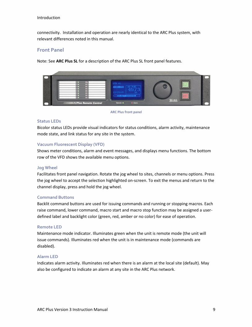
ARC Plus front panel
Status LEDs
Bicolor status LEDs provide visual indicators for status conditions, alarm activity, maintenance
mode state, and link status for any site in the system.
Vacuum Fluorescent Display (VFD)
Shows meter conditions, alarm and event messages, and displays menu functions. The bottom
row of the VFD shows the available menu options.
Jog Wheel
Facilitates front panel navigation. Rotate the jog wheel to sites, channels or menu options. Press
the jog wheel to accept the selection highlighted on-screen. To exit the menus and return to the
channel display, press and hold the jog wheel.
Command Buttons
Backlit command buttons are used for issuing commands and running or stopping macros. Each
raise command, lower command, macro start and macro stop function may be assigned a user-
defined label and backlight color (green, red, amber or no color) for ease of operation.
Remote LED
Maintenance mode indicator. Illuminates green when the unit is remote mode (the unit will
issue commands). Illuminates red when the unit is in maintenance mode (commands are
disabled).
Alarm LED
Indicates alarm activity. Illuminates red when there is an alarm at the local site (default). May
also be configured to indicate an alarm at any site in the ARC Plus network.
Introduction
ARC Plus Version 3 Instruction Manual 10
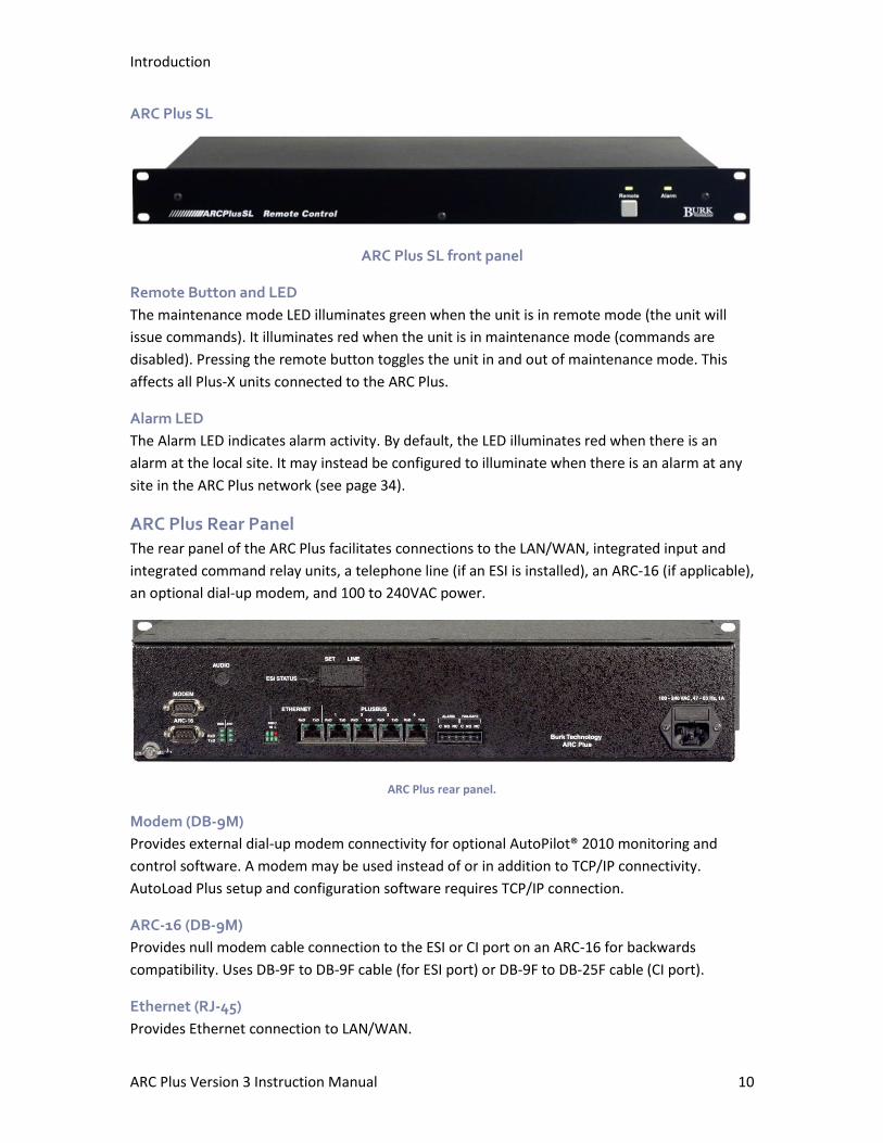
ARC Plus SL
ARC Plus SL front panel
Remote Button and LED
The maintenance mode LED illuminates green when the unit is in remote mode (the unit will
issue commands). It illuminates red when the unit is in maintenance mode (commands are
disabled). Pressing the remote button toggles the unit in and out of maintenance mode. This
affects all Plus-X units connected to the ARC Plus.
Alarm LED
The Alarm LED indicates alarm activity. By default, the LED illuminates red when there is an
alarm at the local site. It may instead be configured to illuminate when there is an alarm at any
site in the ARC Plus network (see page 34).
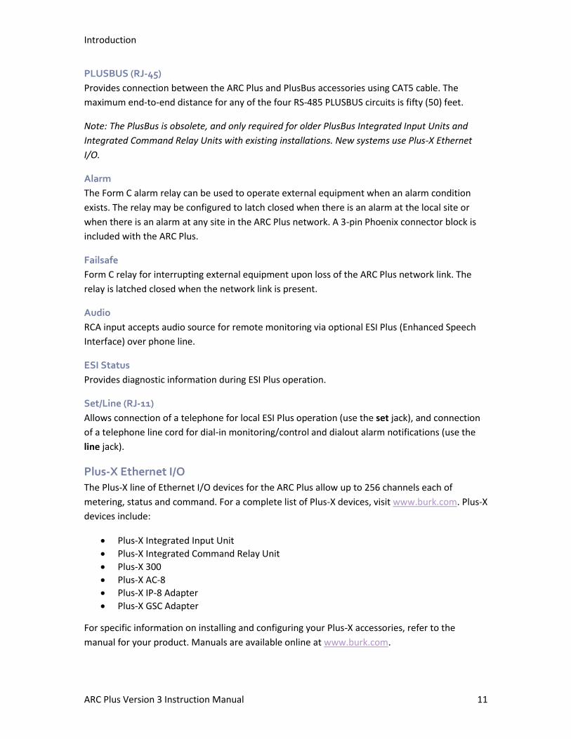
ARC Plus Rear Panel
The rear panel of the ARC Plus facilitates connections to the LAN/WAN, integrated input and
integrated command relay units, a telephone line (if an ESI is installed), an ARC-16 (if applicable),
an optional dial-up modem, and 100 to 240VAC power.
ARC Plus rear panel.
Modem (DB-9M)
Provides external dial-up modem connectivity for optional AutoPilot® 2010 monitoring and
control software. A modem may be used instead of or in addition to TCP/IP connectivity.
AutoLoad Plus setup and configuration software requires TCP/IP connection.
ARC-16 (DB-9M)
Provides null modem cable connection to the ESI or CI port on an ARC-16 for backwards
compatibility. Uses DB-9F to DB-9F cable (for ESI port) or DB-9F to DB-25F cable (CI port).
Ethernet (RJ-45)
Provides Ethernet connection to LAN/WAN.
Introduction
ARC Plus Version 3 Instruction Manual 11
PLUSBUS (RJ-45)
Provides connection between the ARC Plus and PlusBus accessories using CAT5 cable. The
maximum end-to-end distance for any of the four RS-485 PLUSBUS circuits is fifty (50) feet.
Note: The PlusBus is obsolete, and only required for older PlusBus Integrated Input Units and
Integrated Command Relay Units with existing installations. New systems use Plus-X Ethernet
I/O.
Alarm
The Form C alarm relay can be used to operate external equipment when an alarm condition
exists. The relay may be configured to latch closed when there is an alarm at the local site or
when there is an alarm at any site in the ARC Plus network. A 3-pin Phoenix connector block is
included with the ARC Plus.
Failsafe
Form C relay for interrupting external equipment upon loss of the ARC Plus network link. The
relay is latched closed when the network link is present.
Audio
RCA input accepts audio source for remote monitoring via optional ESI Plus (Enhanced Speech
Interface) over phone line.
ESI Status
Provides diagnostic information during ESI Plus operation.
Set/Line (RJ-11)
Allows connection of a telephone for local ESI Plus operation (use the set jack), and connection
of a telephone line cord for dial-in monitoring/control and dialout alarm notifications (use the
line jack).
Plus-X Ethernet I/O
The Plus-X line of Ethernet I/O devices for the ARC Plus allow up to 256 channels each of
metering, status and command. For a complete list of Plus-X devices, visit www.burk.com. Plus-X
devices include:
• Plus-X Integrated Input Unit
• Plus-X Integrated Command Relay Unit
• Plus-X 300
• Plus-X AC-8
• Plus-X IP-8 Adapter
• Plus-X GSC Adapter
For specific information on installing and configuring your Plus-X accessories, refer to the
manual for your product. Manuals are available online at www.burk.com.

Introduction
ARC Plus Version 3 Instruction Manual 12
PlusConnect™ Direct Transmitter Interfaces
The PlusConnect series of direct transmitter interfaces allow a direct, digital connection to
various transmitters without parallel wiring. PlusConnect models are available for many popular
models. For a complete list of supported transmitters, visit www.burk.com.
To install your PlusConnect, follow the instructions in your product’s manual. The installation
procedure is similar to installing any Plus-X Ethernet I/O device.
Introduction
ARC Plus Version 3 Instruction Manual 13
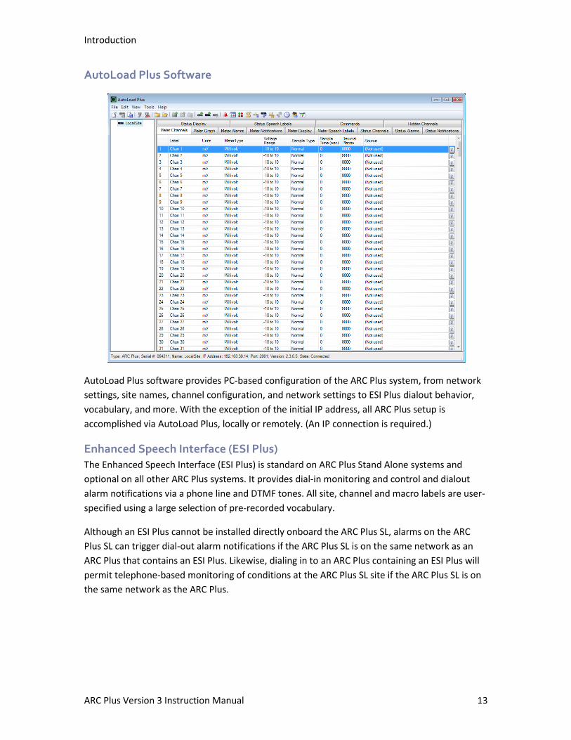
AutoLoad Plus Software
AutoLoad Plus software provides PC-based configuration of the ARC Plus system, from network
settings, site names, channel configuration, and network settings to ESI Plus dialout behavior,
vocabulary, and more. With the exception of the initial IP address, all ARC Plus setup is
accomplished via AutoLoad Plus, locally or remotely. (An IP connection is required.)
Enhanced Speech Interface (ESI Plus)
The Enhanced Speech Interface (ESI Plus) is standard on ARC Plus Stand Alone systems and
optional on all other ARC Plus systems. It provides dial-in monitoring and control and dialout
alarm notifications via a phone line and DTMF tones. All site, channel and macro labels are user-
specified using a large selection of pre-recorded vocabulary.
Although an ESI Plus cannot be installed directly onboard the ARC Plus SL, alarms on the ARC
Plus SL can trigger dial-out alarm notifications if the ARC Plus SL is on the same network as an
ARC Plus that contains an ESI Plus. Likewise, dialing in to an ARC Plus containing an ESI Plus will
permit telephone-based monitoring of conditions at the ARC Plus SL site if the ARC Plus SL is on
the same network as the ARC Plus.
Introduction
ARC Plus Version 3 Instruction Manual 14
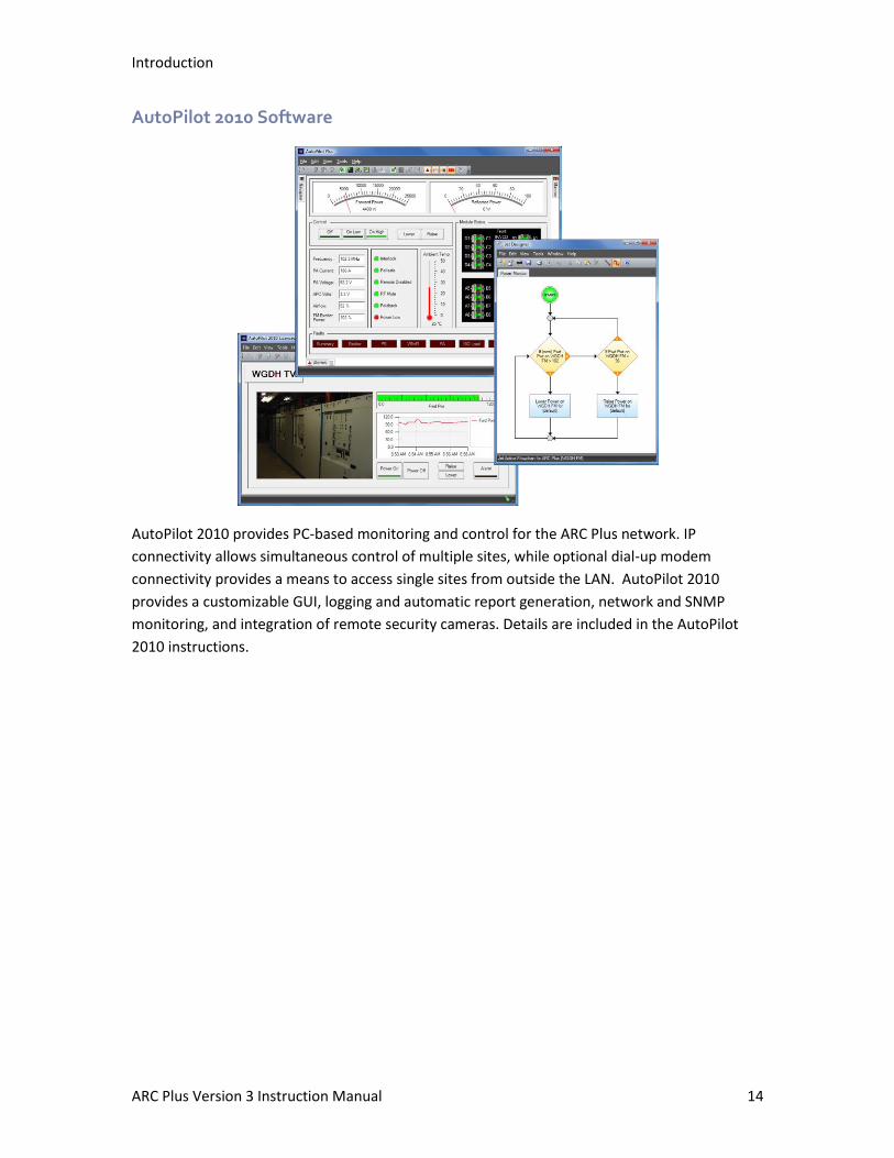
AutoPilot 2010 Software
AutoPilot 2010 provides PC-based monitoring and control for the ARC Plus network. IP
connectivity allows simultaneous control of multiple sites, while optional dial-up modem
connectivity provides a means to access single sites from outside the LAN. AutoPilot 2010
provides a customizable GUI, logging and automatic report generation, network and SNMP
monitoring, and integration of remote security cameras. Details are included in the AutoPilot
2010 instructions.
Introduction
ARC Plus Version 3 Instruction Manual 15
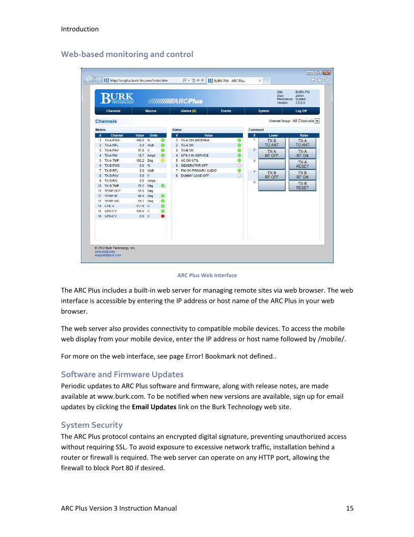
Web-based monitoring and control
ARC Plus Web Interface
The ARC Plus includes a built-in web server for managing remote sites via web browser. The web
interface is accessible by entering the IP address or host name of the ARC Plus in your web
browser.
The web server also provides connectivity to compatible mobile devices. To access the mobile
web display from your mobile device, enter the IP address or host name followed by /mobile/.
For more on the web interface, see page Error! Bookmark not defined..
Software and Firmware Updates
Periodic updates to ARC Plus software and firmware, along with release notes, are made
available at www.burk.com. To be notified when new versions are available, sign up for email
updates by clicking the Email Updates link on the Burk Technology web site.
System Security
The ARC Plus protocol contains an encrypted digital signature, preventing unauthorized access
without requiring SSL. To avoid exposure to excessive network traffic, installation behind a
router or firewall is required. The web server can operate on any HTTP port, allowing the
firewall to block Port 80 if desired.
Hardware Setup
Installing the ARC Plus Unit
Install the ARC Plus in a location with access to your LAN/WAN. If you intend to operate the ARC
Plus in a stand-alone configuration (dial-up modem and telephone access, but no TCP/IP
connection), a network connection must still be available for on-the-bench configuration. A
crossover cable may also be used to connect a computer directly to the ARC Plus for
configuration.
Configuring ARC Plus Network Settings
After installing the ARC Plus in the equipment rack, connect the ARC Plus port marked Ethernet
to your LAN/WAN using CAT5e cable. After obtaining a static IP address, follow these
instructions to configure network settings:
Important! The default IP address on the ARC Plus is the same as the default IP address of
Plus-X devices. If you are installing an ARC Plus and a Plus-X device on the same network,
avoid IP address conflicts by configuring network settings for one unit before connecting the
other unit to your network.
ARC Plus
To establish network settings for the ARC Plus Unit:
1. Power up the ARC Plus. The unit will briefly show the firmware version before loading the main display.
2. Rotate the jog wheel until Config is selected and press the jog wheel to enter the configuration menu. Select the System submenu and then select Network.
3. Enter the private IP, public IP and port values that will identify the ARC Plus as a unique device on the network. The private IP is the IP address you will use to access the ARC Plus on your company LAN/WAN. The public IP address is used when connecting to the ARC Plus from outside the LAN/WAN, provided your network allows connections from outside. If the ARC Plus will not be accessible from outside the network, enter the private IP address in the public IP field.
4. When you are done with the IP address and port settings, the ARC Plus will prompt you for the subnet and gateway settings. Once you have entered those, you will return to the configuration menu. Your ARC Plus can now be accessed by AutoPilot 2010 and AutoLoad Plus.
Note: If you make a mistake while entering your settings, press and hold the jog wheel button
until the network configuration closes and returns you to the top of the menu tree. Navigate to
the network configuration menu again, and enter the new settings.
ARC Plus SL
Network settings on the ARC Plus SL are established using AutoLoad Plus software, which
requires a TCP/IP connection. The default IP address of the ARC Plus SL is 192.168.0.100. In
Hardware Setup
ARC Plus Version 3 Instruction Manual 17
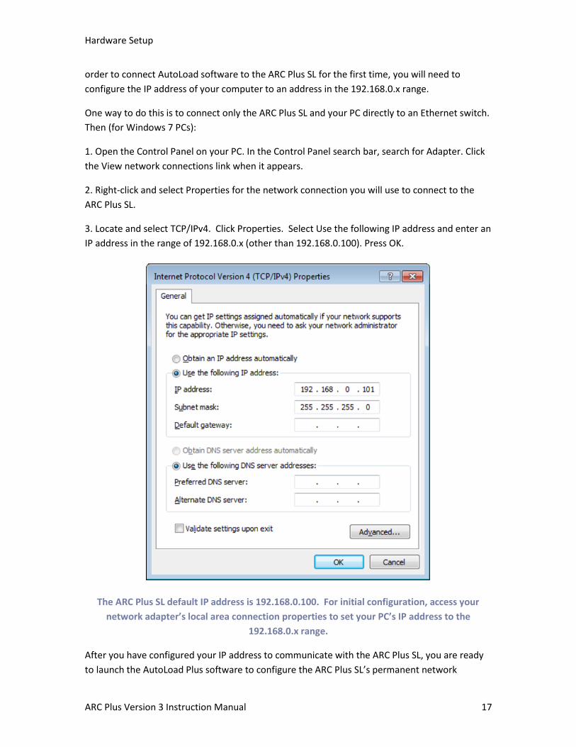
order to connect AutoLoad software to the ARC Plus SL for the first time, you will need to
configure the IP address of your computer to an address in the 192.168.0.x range.
One way to do this is to connect only the ARC Plus SL and your PC directly to an Ethernet switch.
Then (for Windows 7 PCs):
1. Open the Control Panel on your PC. In the Control Panel search bar, search for Adapter. Click
the View network connections link when it appears.
2. Right-click and select Properties for the network connection you will use to connect to the
ARC Plus SL.
3. Locate and select TCP/IPv4. Click Properties. Select Use the following IP address and enter an
IP address in the range of 192.168.0.x (other than 192.168.0.100). Press OK.
The ARC Plus SL default IP address is 192.168.0.100. For initial configuration, access your
network adapter’s local area connection properties to set your PC’s IP address to the
192.168.0.x range.
After you have configured your IP address to communicate with the ARC Plus SL, you are ready
to launch the AutoLoad Plus software to configure the ARC Plus SL’s permanent network

Hardware Setup
ARC Plus Version 3 Instruction Manual 18
settings. See page 27 for instructions on setting the IP address, port number, subnet mask,
gateway, DNS server and HTTP port.
Installing Plus-X I/O Devices
The Plus-X line of Ethernet I/O devices allows connecting various combinations of metering,
status and command channels to the ARC Plus over a LAN, WAN or the Internet. Popular Plus-X
models include the Plus-X Integrated Input Unit, Plus-X Integrated Command Relay Unit, Plus-X
300, PlusConnect™, etc.
The installation procedure for most Plus-X devices is similar. For instructions specific to your
Plus-X accessories, please refer to the manual for your model, available online at
www.burk.com.
Note: If you are installing an older “PlusBus” model Integrated Input Unit or Integrated
Command Relay Unit, see Appendix F.
Configure Network Settings
Begin by configuring your Plus-X device for use on your network. Most Plus-X products are
configured via an onboard web page. Open your web browser and navigate to the default IP
address of the Plus-X device: 192.168.0.100. Access the Network Settings page and assign the IP
address, subnet mask and gateway as appropriate to your network. Enter the IP address of your
ARC Plus where prompted.
Note: Some PlusConnect models are configured via telnet or a serial connection. See your
PlusConnect manual for more information.
Add your Device to the ARC Plus
Once the Plus-X device is configured for your network, you will need to add it to the ARC Plus
using AutoLoad Plus. If you have not already installed AutoLoad Plus, please do so now. The
current version of AutoLoad Plus is available online at www.burk.com.
Using AutoLoad Plus, connect to your ARC Plus using its IP address. From the Edit menu, select
Plus-X Devices. Click the Add… button in the Plus-X Devices toolbar. Using the Device type
dropdown list, select the model Plus-X device you are adding, and enter the IP address you
assigned it earlier.
Note: If your Plus-X device model does not appear in the dropdown list, you may need to
download its XML definition file. Plus-X XML definition files and installation instructions are
available online at www.burk.com.
Once you have added the Plus-X device to the ARC Plus, Plus-X device channels must be
assigned to channels on the ARC Plus. Plus-X channels may be assigned manually or
automatically. Automatic assignment is recommended in most cases. Select the channel number
where you want to start assigning channels. For your first Plus-X device, starting at channel 1 is
typical. Leave the “Map the default set of channels” checkbox checked and press OK.If installing
Hardware Setup
ARC Plus Version 3 Instruction Manual 19
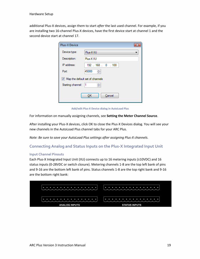
additional Plus-X devices, assign them to start after the last used channel. For example, if you
are installing two 16-channel Plus-X devices, have the first device start at channel 1 and the
second device start at channel 17.
Add/edit Plus-X Device dialog in AutoLoad Plus
For information on manually assigning channels, see Setting the Meter Channel Source.
After installing your Plus-X devices, click OK to close the Plus-X Devices dialog. You will see your
new channels in the AutoLoad Plus channel tabs for your ARC Plus.
Note: Be sure to save your AutoLoad Plus settings after assigning Plus-X channels.
Connecting Analog and Status Inputs on the Plus-X Integrated Input Unit
Input Channel Pinouts
Each Plus-X Integrated Input Unit (IIU) connects up to 16 metering inputs (±10VDC) and 16
status inputs (0-28VDC or switch closure). Metering channels 1-8 are the top left bank of pins
and 9-16 are the bottom left bank of pins. Status channels 1-8 are the top right bank and 9-16
are the bottom right bank:
Hardware Setup
ARC Plus Version 3 Instruction Manual 20
Each channel has a pin for common ground (left) and a pin for the signal voltage (right), as
shown in the table below.
CH 1 CH 2 CH 3 CH 4 CH 4 CH 6 CH 7 CH 8
- + - + - + - + - + - + - + - + - + - + - + - + - + - + - + - +
CH 9 CH 10 CH 11 CH 12 CH 13 CH 14 CH 15 CH 16
IIU Rear Panel Connector Pinouts. Analog and status pinouts are identical. Channels 17-32, 33-48, etc. are connected on subsequent IIUs in the same fashion.
Four 16-pin connector blocks are included to facilitate equipment wiring, two blocks for analog
channels, and two for status channels. Analog channels are connected on the left side of the IIU
rear panel, and status channels are connected on the right, as shown above.
Secure equipment wiring to the connector blocks using the built-in set screws before attaching
the connector block to the appropriate rear panel connectors.
Connecting Command Channels on the Plus-X Integrated Command Relay Unit
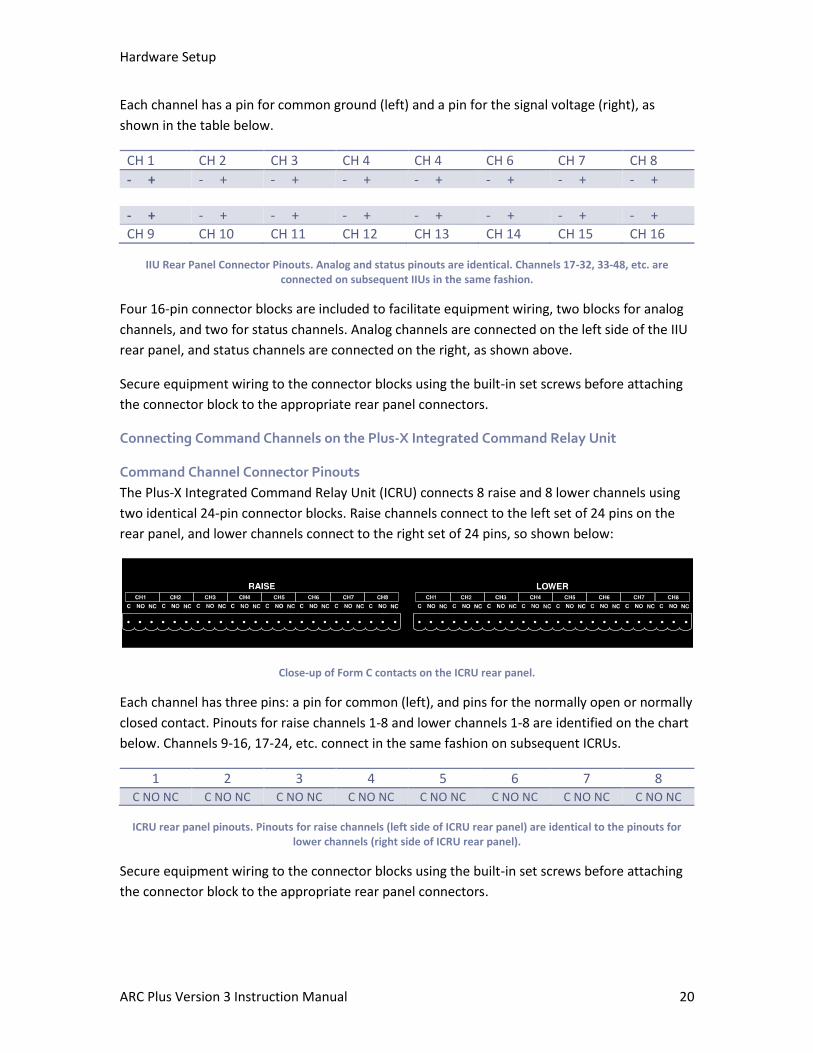
Command Channel Connector Pinouts
The Plus-X Integrated Command Relay Unit (ICRU) connects 8 raise and 8 lower channels using
two identical 24-pin connector blocks. Raise channels connect to the left set of 24 pins on the
rear panel, and lower channels connect to the right set of 24 pins, so shown below:
Close-up of Form C contacts on the ICRU rear panel.
Each channel has three pins: a pin for common (left), and pins for the normally open or normally
closed contact. Pinouts for raise channels 1-8 and lower channels 1-8 are identified on the chart
below. Channels 9-16, 17-24, etc. connect in the same fashion on subsequent ICRUs.
1 2 3 4 5 6 7 8 C NO NC C NO NC C NO NC C NO NC C NO NC C NO NC C NO NC C NO NC
ICRU rear panel pinouts. Pinouts for raise channels (left side of ICRU rear panel) are identical to the pinouts for lower channels (right side of ICRU rear panel).
Secure equipment wiring to the connector blocks using the built-in set screws before attaching
the connector block to the appropriate rear panel connectors.

Hardware Setup
ARC Plus Version 3 Instruction Manual 21
Connecting an ARC-16 to the ARC Plus
Note: If you have purchased a Plus-X Dual IP-8 Adapter, refer to the manual for the adapter for
information on connecting your IP-8(s) directly to the ARC Plus. For information on the Plus-X
Dual IP-8 Adapter, visit www.burk.com.
The ARC Plus is backwards compatible with the ARC-16 broadcast remote control, allowing
operators to manage ARC-16 sites via the ARC Plus front panel, web server, AutoPilot 2010 or
ESI Plus. Add up to four interconnected ARC-16 units to the ARC Plus by connecting a DB-9F to
DB-9F null modem cable from the ARC Plus rear panel port marked ARC-16 to the ESI COM port
on one ARC-16. If a CI is installed on the ARC-16, us a DB-9F to DB-25F cable. Up to three
additional ARC-16s can communicate with the ARC Plus using this connection.
Protecting Against Transients and Power Surges
All units in the ARC Plus system are equipped with onboard surge protection designed to
prevent damage due to power surges. However, onboard protection is not effective without
proper grounding. Use the rear panel grounding lugs to connect the equipment chassis to an
appropriate grounding mechanism.
For units connected to a telephone line, either via an ESI (for dial-up telephone control) or via an
external dialup modem, external surge protection on the phone line is strongly recommended.
The Burk Technology TS-1 is designed specifically for this purpose. External protection for the
Ethernet connection is also recommended.
Important Safety Information
Maintenance Mode
Prior to performing any maintenance on connected site equipment, operators MUST engage
maintenance mode via the front panel of the ARC Plus system. This disables all commands,
whether originating from the local ARC Plus, a remote ARC Plus, AutoPilot 2010 software, web
browser, or ESI Plus. This behavior is different from the ARC-16 maintenance mode, which does
not prevent local commands.
To turn maintenance mode on, start at the top level of the front panel menus and select MAINT.
When prompted to set the maintenance mode condition, rotate the jog wheel to ON and press
to accept. The REMOTE LED on the front panel of the unit turns red. When the local site is
selected for viewing on the front panel, the MAINT flag appears on the display. If a remote unit
is used to view a site that is in maintenance mode, that unit will also show the MAINT flag while
the site is selected.
When it is safe to restore command functionality to the system, turn maintenance mode off by
rotating the jog wheel to OFF and pressing the jog wheel to accept. The REMOTE LED on the
front panel of the unit turns green, and the MAINT flag disappears. For safety reasons, it is not
Hardware Setup
ARC Plus Version 3 Instruction Manual 22
possible to enable or disable maintenance mode by any means other than the front panel of the
ARC Plus at the local site.
Important! For safety reasons, it is not possible to enable or disable maintenance mode by any
means other than the front panel of the ARC Plus at the local site.
ARC Plus
On the ARC Plus system, turn maintenance mode on by starting at the top level of the front
panel menus and selecting MAINT. When prompted to set the maintenance mode condition,
rotate the jog wheel to ON and press to accept. The REMOTE LED on the front panel of the unit
turns red. When the local site is selected for viewing on the front panel, the MAINT flag appears
on the display. If a remote unit is used to view a site that is in maintenance mode, that unit will
also show the MAINT flag while the site is selected.
When it is safe to restore command functionality to the system, turn maintenance mode off by
rotating the jog wheel to OFF and pressing the jog wheel to accept. The REMOTE LED on the
front panel of the unit turns green, and the MAINT flag disappears.
ARC Plus SL
On the ARC Plus SL, toggle maintenance mode by pressing the front panel REMOTE button. A
green REMOTE LED indicates the unit is in remote mode (the unit will issue commands), and a
red REMOTE LED indicates the unit is in maintenance mode (the unit will not issue commands).
Power Recovery Behavior
It is recommended to connect the ARC Plus system to a suitable UPS to prevent unexpected
power loss.
Plus-X ICRU Models
If power is removed from the ARC Plus system, the position of the raise and lower relays on
Plus-X devices will be restored upon power recovery.
PlusBus ICRU Models
For legacy PlusBus ICRU models, AutoLoad Plus software allows users to determine whether the
ARC Plus restores the relay state on power recovery, or whether the system comes back online
with all relays open. For more information, see page 33.
If the ARC Plus is configured to restore the relay state on power recovery, do not begin
maintenance on any site equipment during a power interruption without first unplugging the
ICRUs.
Configuring System Settings
To get started with configuration, you will need to download and install AutoLoad Plus software
if you have not done so already. The latest version of AutoLoad Plus is available from Burk
Technology’s website at www.burk.com. AutoLoad Plus allows you to easily set up and
administer your ARC Plus system using a PC. With AutoLoad Plus, you have access to every
system parameter such as metering (including calibration), status, and command channel
settings, user security, front-panel display options, time and date settings, alarm notifications,
ESI Plus settings, macros, and more.
Once connected, the configuration is read and edited directly from the ARC Plus. When you save
changes, the changes are loaded directly to the unit.
Note: Only System level users can access AutoLoad Plus. The site administrator(s) will be able to
define access levels for each individual user. Software Installation
Connecting to the ARC Plus
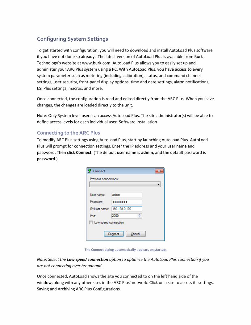
To modify ARC Plus settings using AutoLoad Plus, start by launching AutoLoad Plus. AutoLoad
Plus will prompt for connection settings. Enter the IP address and your user name and
password. Then click Connect. (The default user name is admin, and the default password is
password.)
The Connect dialog automatically appears on startup.
Note: Select the Low speed connection option to optimize the AutoLoad Plus connection if you
are not connecting over broadband.
Once connected, AutoLoad shows the site you connected to on the left hand side of the
window, along with any other sites in the ARC Plus’ network. Click on a site to access its settings.
Saving and Archiving ARC Plus Configurations
Configuring System Settings
ARC Plus Version 3 Instruction Manual 24
Saving Configuration Changes to the ARC Plus
Any changes you make must be saved to the ARC Plus before they become active. After making
a configuration edit, click the save icon in the toolbar or go to the File menu and choose Save. If
you make unsaved configuration changes in AutoLoad Plus and wish to undo them, go to the
File menu and choose Revert. You must revert any changes before saving them to the ARC Plus.
Archiving ARC Plus Settings to the PC
To save a copy of the ARC Plus configuration to your PC, select Save to File... from the File
menu. Give the configuration a file name and press Save.
Loading Archived Settings
To load archived settings to an ARC Plus, connect to the desired ARC Plus site and click the Open
from File... toolbar icon. Select the desired file, click Open, and the settings will populate in
AutoLoad Plus. Press the Save toolbar icon to save the configuration to the ARC Plus.
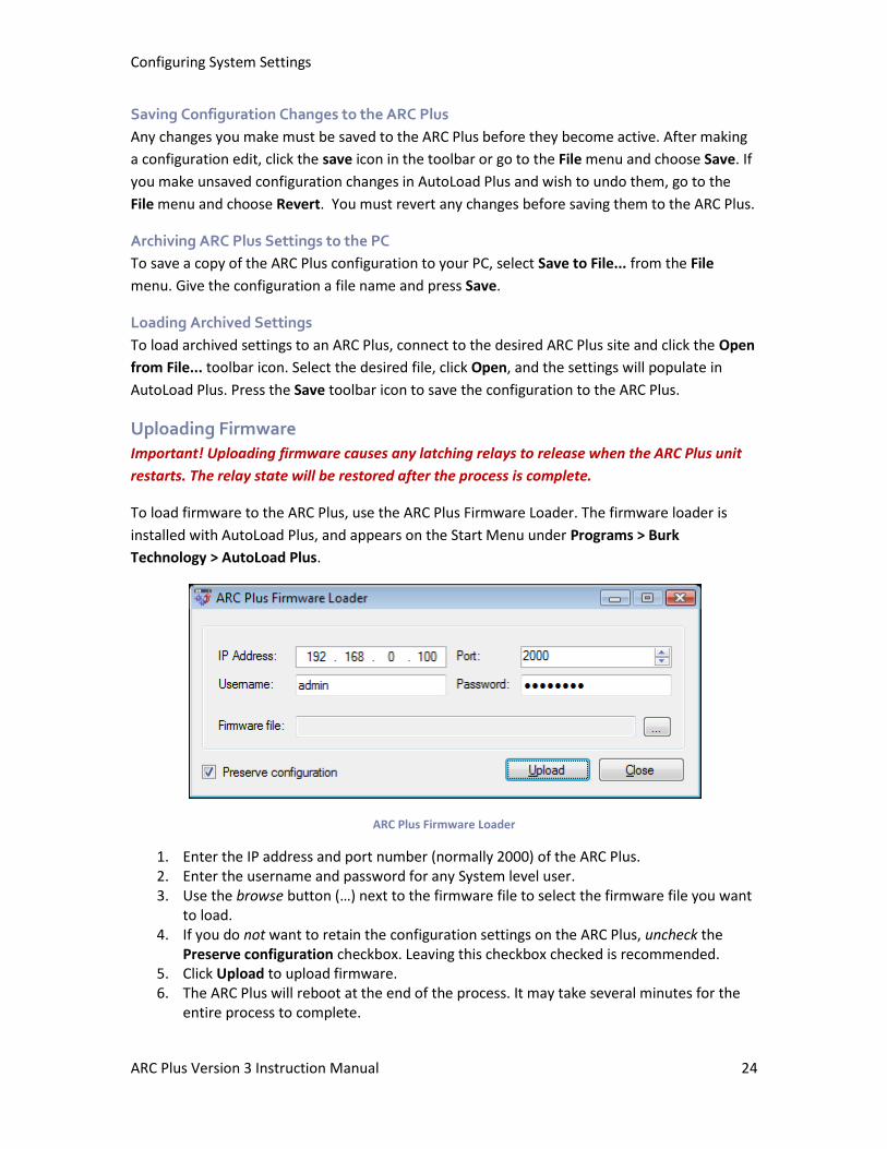
Uploading Firmware
Important! Uploading firmware causes any latching relays to release when the ARC Plus unit
restarts. The relay state will be restored after the process is complete.
To load firmware to the ARC Plus, use the ARC Plus Firmware Loader. The firmware loader is
installed with AutoLoad Plus, and appears on the Start Menu under Programs > Burk
Technology > AutoLoad Plus.
ARC Plus Firmware Loader
1. Enter the IP address and port number (normally 2000) of the ARC Plus. 2. Enter the username and password for any System level user. 3. Use the browse button (…) next to the firmware file to select the firmware file you want
to load. 4. If you do not want to retain the configuration settings on the ARC Plus, uncheck the
Preserve configuration checkbox. Leaving this checkbox checked is recommended. 5. Click Upload to upload firmware. 6. The ARC Plus will reboot at the end of the process. It may take several minutes for the
entire process to complete.
Configuring System Settings
ARC Plus Version 3 Instruction Manual 25
Changing the Site Name
To change the name of the ARC Plus site, highlight the ARC Plus icon in the site list, right click
and select Rename. Rename the site as desired (up to 12 characters).
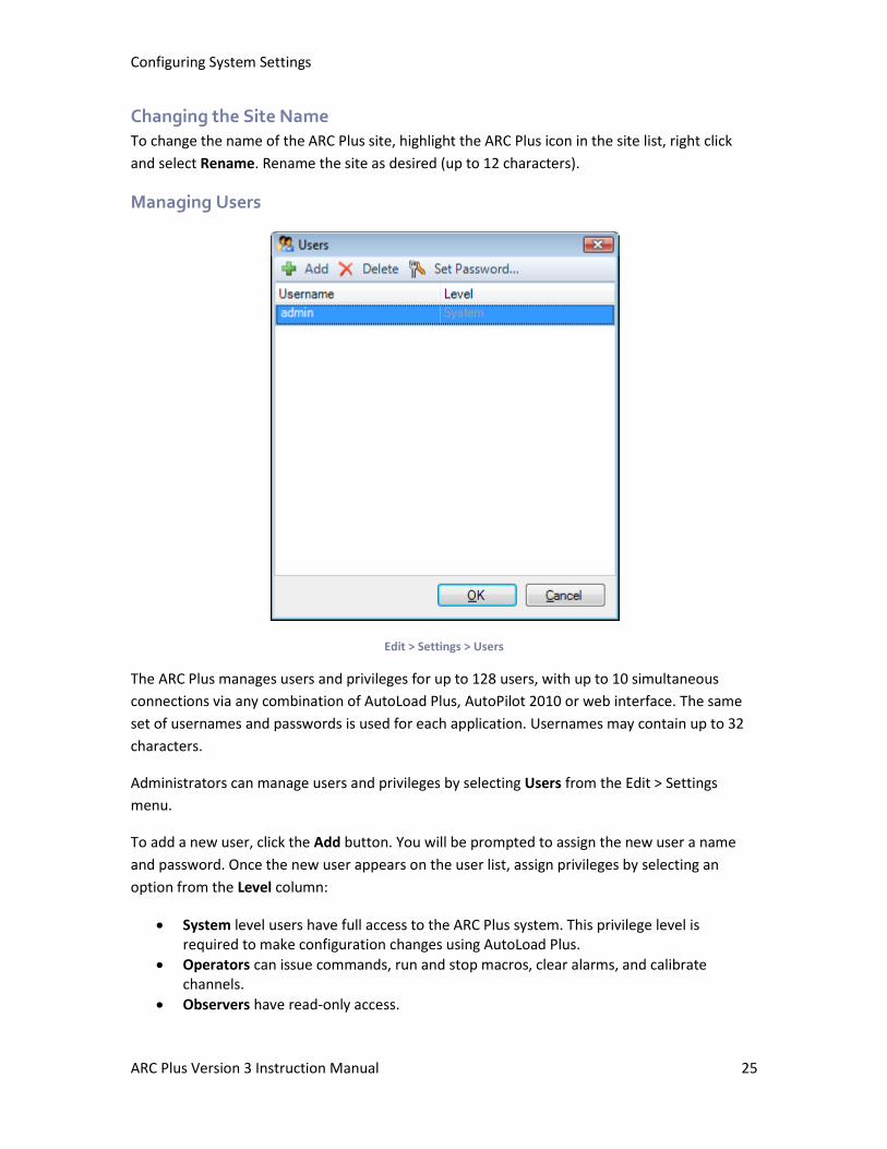
Managing Users
Edit > Settings > Users
The ARC Plus manages users and privileges for up to 128 users, with up to 10 simultaneous
connections via any combination of AutoLoad Plus, AutoPilot 2010 or web interface. The same
set of usernames and passwords is used for each application. Usernames may contain up to 32
characters.
Administrators can manage users and privileges by selecting Users from the Edit > Settings
menu.
To add a new user, click the Add button. You will be prompted to assign the new user a name
and password. Once the new user appears on the user list, assign privileges by selecting an
option from the Level column:
• System level users have full access to the ARC Plus system. This privilege level is required to make configuration changes using AutoLoad Plus.
• Operators can issue commands, run and stop macros, clear alarms, and calibrate channels.
• Observers have read-only access.
Configuring System Settings
ARC Plus Version 3 Instruction Manual 26
You can rename an existing user by simply editing the Username field. To change the password,
select the user and click the Set Password… button in the toolbar. Use the Delete button to
remove a user entirely.
Note: While it is possible to rename the default admin user, you cannot delete this user or
change its access level. Changing the password for the admin user is strongly recommended.
Note: Passwords are case sensitive; usernames are not.
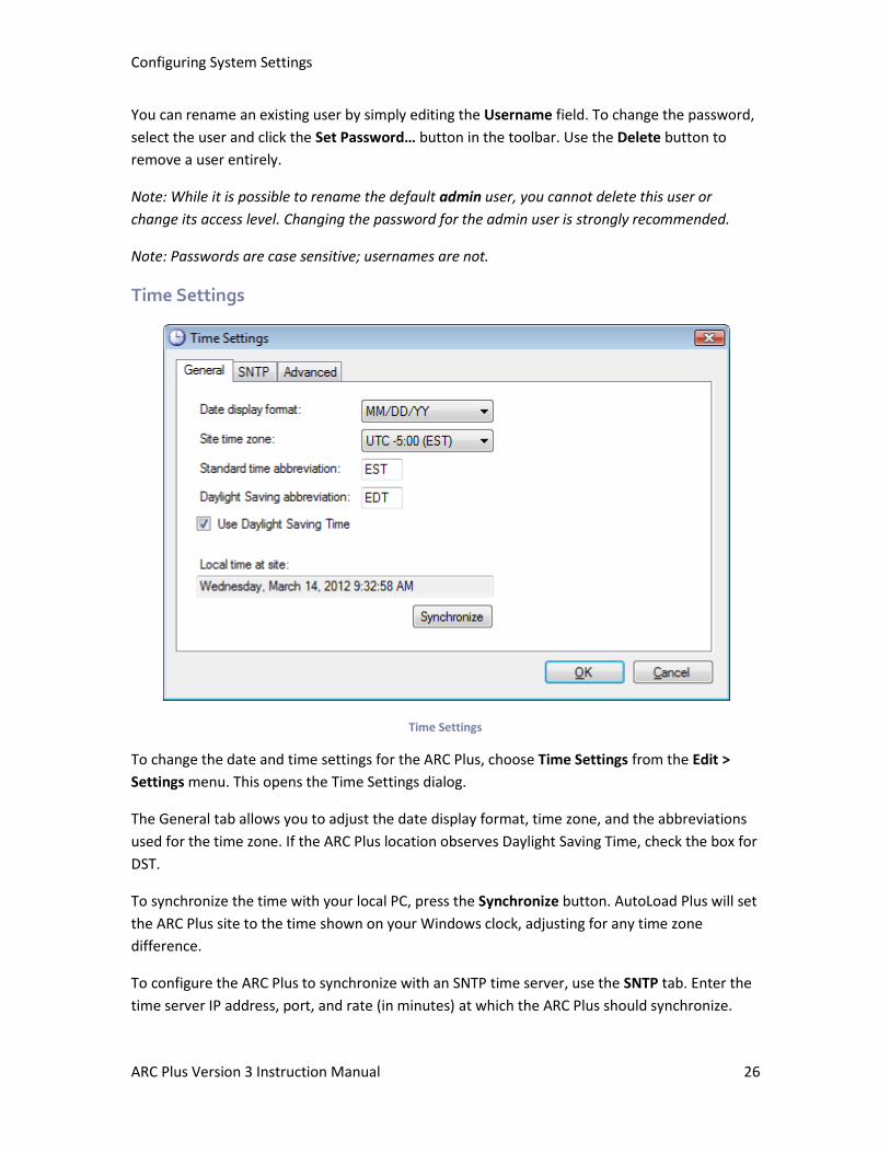
Time Settings
Time Settings
To change the date and time settings for the ARC Plus, choose Time Settings from the Edit >
Settings menu. This opens the Time Settings dialog.
The General tab allows you to adjust the date display format, time zone, and the abbreviations
used for the time zone. If the ARC Plus location observes Daylight Saving Time, check the box for
DST.
To synchronize the time with your local PC, press the Synchronize button. AutoLoad Plus will set
the ARC Plus site to the time shown on your Windows clock, adjusting for any time zone
difference.
To configure the ARC Plus to synchronize with an SNTP time server, use the SNTP tab. Enter the
time server IP address, port, and rate (in minutes) at which the ARC Plus should synchronize.
Configuring System Settings
ARC Plus Version 3 Instruction Manual 27
Note: Using an SNTP server is recommended to ensure accurate timestamps and scheduled
operations on the ARC Plus.
The Advanced tab allows you to change the rules for Daylight Saving Time. The ARC Plus uses
United States rules for DST by default. Changing these rules is only necessary for locations that
follow different rules.
Network Settings
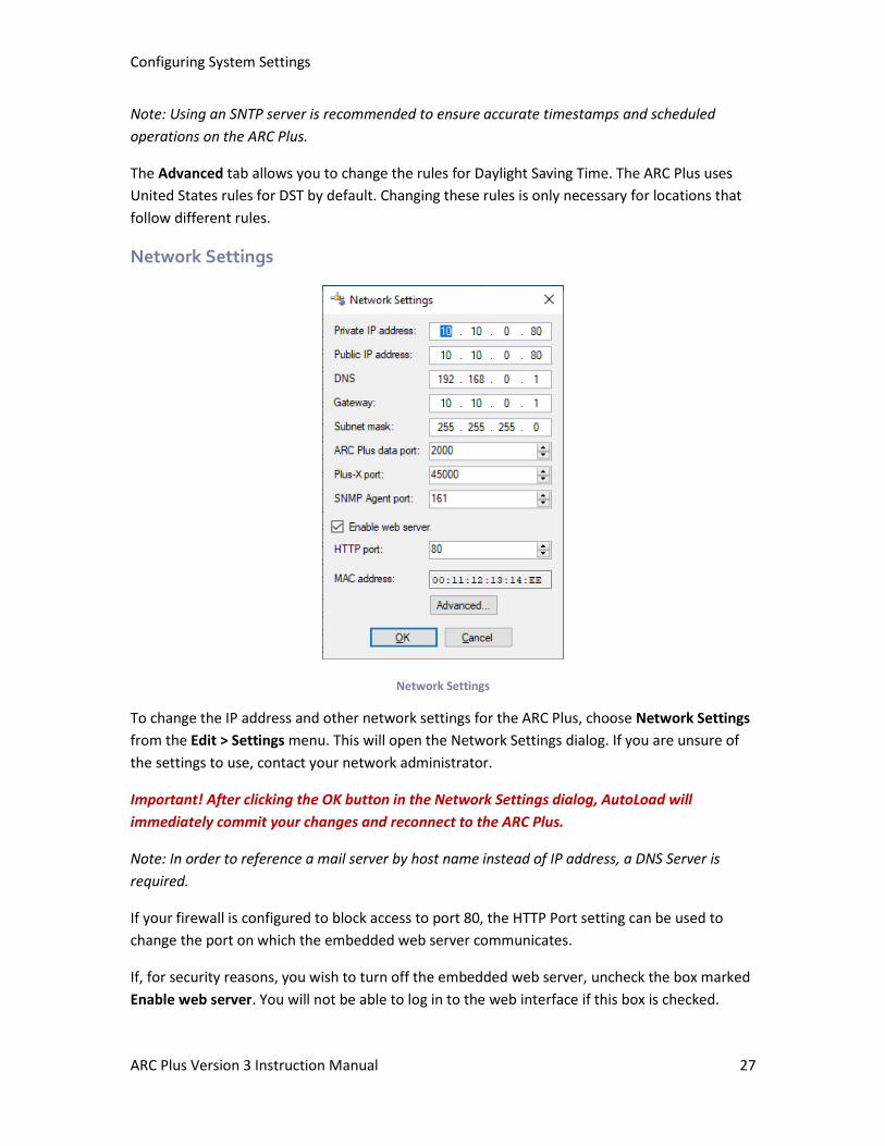
Network Settings
To change the IP address and other network settings for the ARC Plus, choose Network Settings
from the Edit > Settings menu. This will open the Network Settings dialog. If you are unsure of
the settings to use, contact your network administrator.
Important! After clicking the OK button in the Network Settings dialog, AutoLoad will
immediately commit your changes and reconnect to the ARC Plus.
Note: In order to reference a mail server by host name instead of IP address, a DNS Server is
required.
If your firewall is configured to block access to port 80, the HTTP Port setting can be used to
change the port on which the embedded web server communicates.
If, for security reasons, you wish to turn off the embedded web server, uncheck the box marked
Enable web server. You will not be able to log in to the web interface if this box is checked.
Configuring System Settings
ARC Plus Version 3 Instruction Manual 28
To allow the ARC Plus Touch to communicate over TCP/IP networks with longer than typical network delays, click the Advanced button and click the Enable Longer TCP Timeouts checkbox.
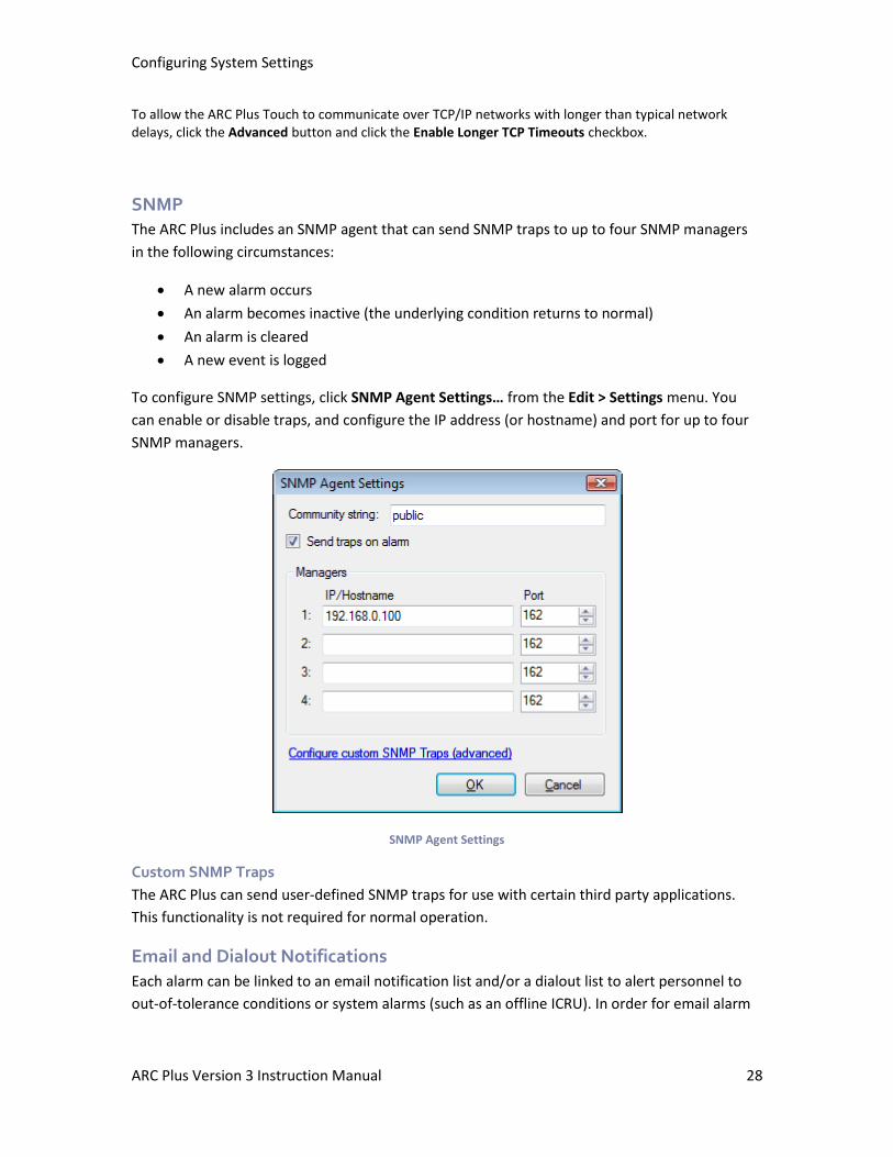
SNMP
The ARC Plus includes an SNMP agent that can send SNMP traps to up to four SNMP managers
in the following circumstances:
• A new alarm occurs
• An alarm becomes inactive (the underlying condition returns to normal)
• An alarm is cleared
• A new event is logged
To configure SNMP settings, click SNMP Agent Settings… from the Edit > Settings menu. You
can enable or disable traps, and configure the IP address (or hostname) and port for up to four
SNMP managers.
SNMP Agent Settings
Custom SNMP Traps
The ARC Plus can send user-defined SNMP traps for use with certain third party applications.
This functionality is not required for normal operation.
Email and Dialout Notifications
Each alarm can be linked to an email notification list and/or a dialout list to alert personnel to
out-of-tolerance conditions or system alarms (such as an offline ICRU). In order for email alarm
Configuring System Settings
ARC Plus Version 3 Instruction Manual 29
notifications to be sent, the ARC Plus must have access to an SMTP server. For dialout
notification, the optional ESI Plus must be installed.
Configuring notifications is a two-step process: first, the notification lists must be created in the
Alarm Notifications window; then the alarm conditions must be configured to use the
appropriate lists. This is accomplished in the Status Notifications and Meter Notifications tabs of
the channel configuration area, after you have configured status and metering channels.
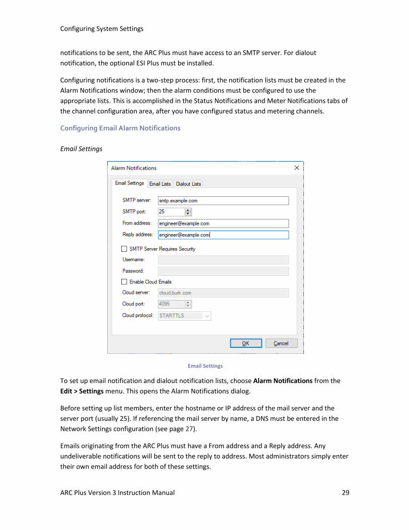
Configuring Email Alarm Notifications
Email Settings
Email Settings
To set up email notification and dialout notification lists, choose Alarm Notifications from the
Edit > Settings menu. This opens the Alarm Notifications dialog.
Before setting up list members, enter the hostname or IP address of the mail server and the
server port (usually 25). If referencing the mail server by name, a DNS must be entered in the
Network Settings configuration (see page 27).
Emails originating from the ARC Plus must have a From address and a Reply address. Any
undeliverable notifications will be sent to the reply to address. Most administrators simply enter
their own email address for both of these settings.
Configuring System Settings
ARC Plus Version 3 Instruction Manual 30
If your server requires authentication, enter the User name and User password where
prompted.
If your email server requires TLS encryption for emails passing through its server, you must also
enable cloud emails with a cloud server of cloud.burk.com, cloud port of 4095 and cloud
protocol set to STARTTLS. This allows the ARC Plus to send TLS encrypted emails by first passing
though the cloud server to do the encryption which then gets forwarded to you email server.
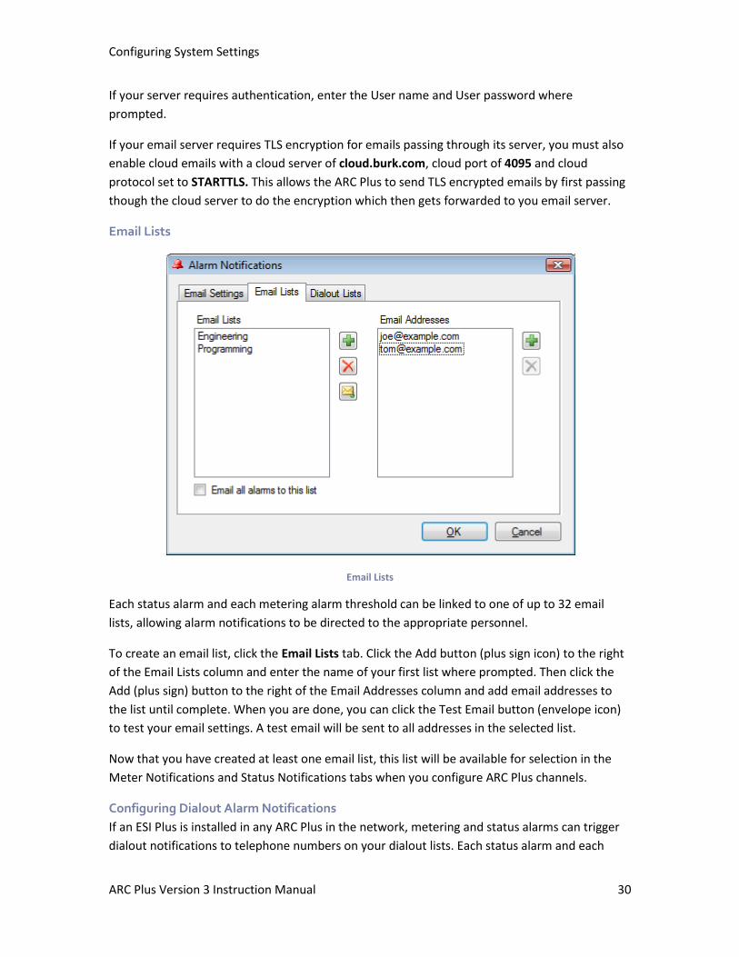
Email Lists
Email Lists
Each status alarm and each metering alarm threshold can be linked to one of up to 32 email
lists, allowing alarm notifications to be directed to the appropriate personnel.
To create an email list, click the Email Lists tab. Click the Add button (plus sign icon) to the right
of the Email Lists column and enter the name of your first list where prompted. Then click the
Add (plus sign) button to the right of the Email Addresses column and add email addresses to
the list until complete. When you are done, you can click the Test Email button (envelope icon)
to test your email settings. A test email will be sent to all addresses in the selected list.
Now that you have created at least one email list, this list will be available for selection in the
Meter Notifications and Status Notifications tabs when you configure ARC Plus channels.
Configuring Dialout Alarm Notifications
If an ESI Plus is installed in any ARC Plus in the network, metering and status alarms can trigger
dialout notifications to telephone numbers on your dialout lists. Each status alarm and each
Configuring System Settings
ARC Plus Version 3 Instruction Manual 31
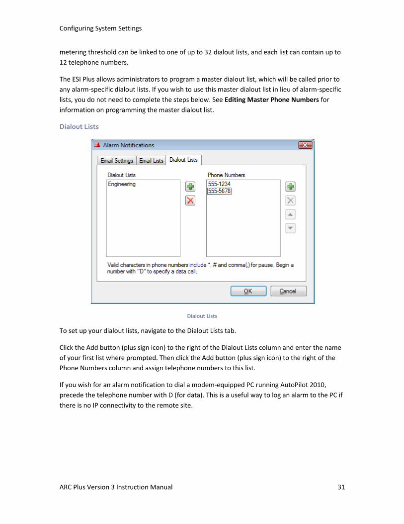
metering threshold can be linked to one of up to 32 dialout lists, and each list can contain up to
12 telephone numbers.
The ESI Plus allows administrators to program a master dialout list, which will be called prior to
any alarm-specific dialout lists. If you wish to use this master dialout list in lieu of alarm-specific
lists, you do not need to complete the steps below. See Editing Master Phone Numbers for
information on programming the master dialout list.
Dialout Lists
Dialout Lists
To set up your dialout lists, navigate to the Dialout Lists tab.
Click the Add button (plus sign icon) to the right of the Dialout Lists column and enter the name
of your first list where prompted. Then click the Add button (plus sign icon) to the right of the
Phone Numbers column and assign telephone numbers to this list.
If you wish for an alarm notification to dial a modem-equipped PC running AutoPilot 2010,
precede the telephone number with D (for data). This is a useful way to log an alarm to the PC if
there is no IP connectivity to the remote site.
Configuring System Settings
ARC Plus Version 3 Instruction Manual 32
Mapping the Front Panel LEDs
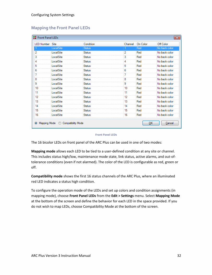
Front Panel LEDs
The 16 bicolor LEDs on front panel of the ARC Plus can be used in one of two modes:
Mapping mode allows each LED to be tied to a user-defined condition at any site or channel.
This includes status high/low, maintenance mode state, link status, active alarms, and out-of-
tolerance conditions (even if not alarmed). The color of the LED is configurable as red, green or
off.
Compatibility mode shows the first 16 status channels of the ARC Plus, where an illuminated
red LED indicates a status high condition.
To configure the operation mode of the LEDs and set up colors and condition assignments (in
mapping mode), choose Front Panel LEDs from the Edit > Settings menu. Select Mapping Mode
at the bottom of the screen and define the behavior for each LED in the space provided. If you
do not wish to map LEDs, choose Compatibility Mode at the bottom of the screen.
Configuring System Settings
ARC Plus Version 3 Instruction Manual 33
Site Settings
Many system settings are user-definable and can be configured by accessing the Site Settings
dialog from the Edit > Settings menu.
Startup Behavior
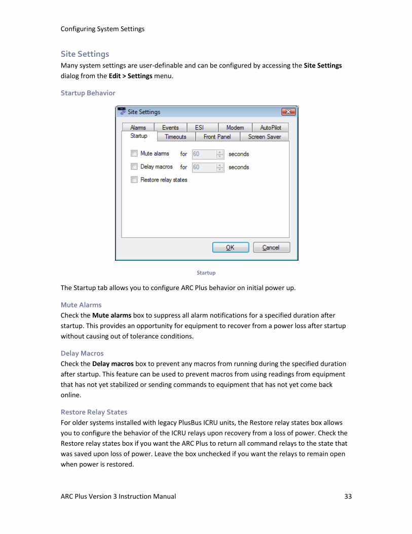
Startup
The Startup tab allows you to configure ARC Plus behavior on initial power up.
Mute Alarms
Check the Mute alarms box to suppress all alarm notifications for a specified duration after
startup. This provides an opportunity for equipment to recover from a power loss after startup
without causing out of tolerance conditions.
Delay Macros
Check the Delay macros box to prevent any macros from running during the specified duration
after startup. This feature can be used to prevent macros from using readings from equipment
that has not yet stabilized or sending commands to equipment that has not yet come back
online.
Restore Relay States
For older systems installed with legacy PlusBus ICRU units, the Restore relay states box allows
you to configure the behavior of the ICRU relays upon recovery from a loss of power. Check the
Restore relay states box if you want the ARC Plus to return all command relays to the state that
was saved upon loss of power. Leave the box unchecked if you want the relays to remain open
when power is restored.
Configuring System Settings
ARC Plus Version 3 Instruction Manual 34
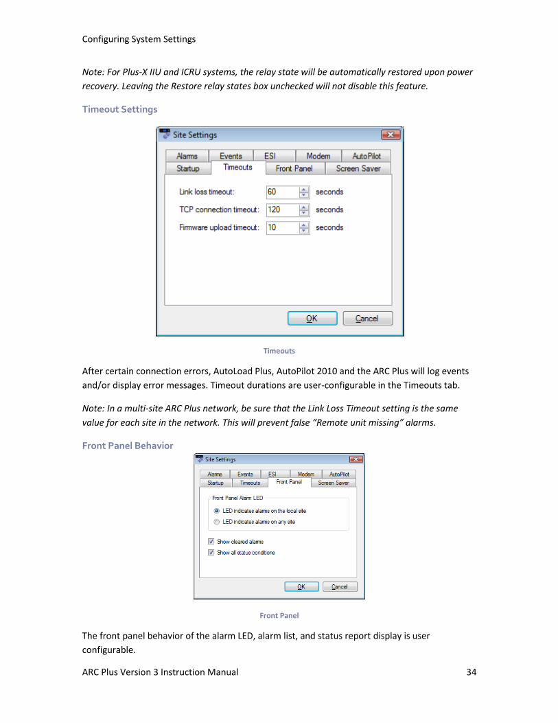
Note: For Plus-X IIU and ICRU systems, the relay state will be automatically restored upon power
recovery. Leaving the Restore relay states box unchecked will not disable this feature.
Timeout Settings
Timeouts
After certain connection errors, AutoLoad Plus, AutoPilot 2010 and the ARC Plus will log events
and/or display error messages. Timeout durations are user-configurable in the Timeouts tab.
Note: In a multi-site ARC Plus network, be sure that the Link Loss Timeout setting is the same
value for each site in the network. This will prevent false “Remote unit missing” alarms.
Front Panel Behavior
Front Panel
The front panel behavior of the alarm LED, alarm list, and status report display is user
configurable.
Configuring System Settings
ARC Plus Version 3 Instruction Manual 35
ARC Plus and ARC Plus SL
Under Front Panel Alarm LED, the LED indicates alarm on local site option causes the front
panel LED to illuminate when there is an alarm condition on any of the equipment physically
connected to the unit. The LED indicates alarm on any site option causes the LED to illuminate
when any site in the ARC Plus network has an alarm.
ARC Plus Only
If you want cleared alarms to appear in the front panel alarm list, check the box marked Show
cleared alarms. Cleared alarms appear beneath uncleared alarms and show the date and time
they were cleared.
If you want the status report to show status off and status on messages for every channel, check
the box marked Show all status conditions. Otherwise, the front panel status report will only
include status on messages.
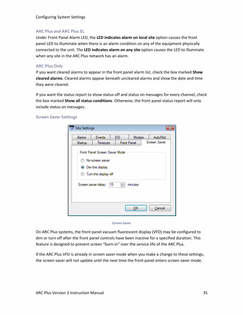
Screen Saver Settings
Screen Saver
On ARC Plus systems, the front panel vacuum fluorescent display (VFD) may be configured to
dim or turn off after the front panel controls have been inactive for a specified duration. This
feature is designed to prevent screen “burn-in” over the service life of the ARC Plus.
If the ARC Plus VFD is already in screen saver mode when you make a change to these settings,
the screen saver will not update until the next time the front panel enters screen saver mode.
Configuring System Settings
ARC Plus Version 3 Instruction Manual 36
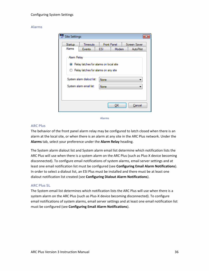
Alarms
Alarms
ARC Plus
The behavior of the front panel alarm relay may be configured to latch closed when there is an
alarm at the local site, or when there is an alarm at any site in the ARC Plus network. Under the
Alarms tab, select your preference under the Alarm Relay heading.
The System alarm dialout list and System alarm email list determine which notification lists the
ARC Plus will use when there is a system alarm on the ARC Plus (such as Plus-X device becoming
disconnected). To configure email notifications of system alarms, email server settings and at
least one email notification list must be configured (see Configuring Email Alarm Notifications).
In order to select a dialout list, an ESI Plus must be installed and there must be at least one
dialout notification list created (see Configuring Dialout Alarm Notifications).
ARC Plus SL
The System email list determines which notification lists the ARC Plus will use when there is a
system alarm on the ARC Plus (such as Plus-X device becoming disconnected). To configure
email notifications of system alarms, email server settings and at least one email notification list
must be configured (see Configuring Email Alarm Notifications).
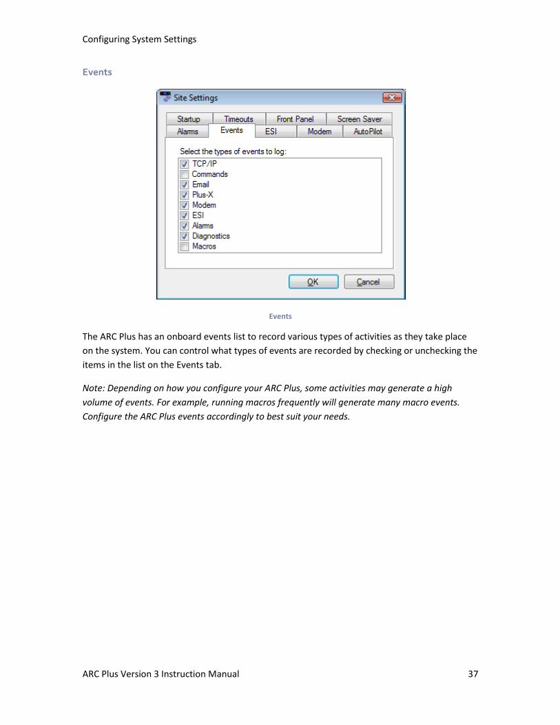
Configuring System Settings
ARC Plus Version 3 Instruction Manual 37
Events
Events
The ARC Plus has an onboard events list to record various types of activities as they take place
on the system. You can control what types of events are recorded by checking or unchecking the
items in the list on the Events tab.
Note: Depending on how you configure your ARC Plus, some activities may generate a high
volume of events. For example, running macros frequently will generate many macro events.
Configure the ARC Plus events accordingly to best suit your needs.
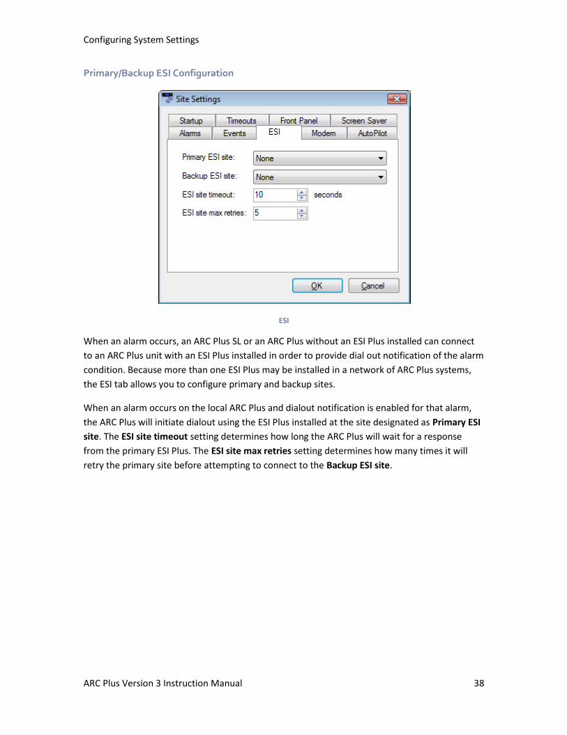
Configuring System Settings
ARC Plus Version 3 Instruction Manual 38
Primary/Backup ESI Configuration
ESI
When an alarm occurs, an ARC Plus SL or an ARC Plus without an ESI Plus installed can connect
to an ARC Plus unit with an ESI Plus installed in order to provide dial out notification of the alarm
condition. Because more than one ESI Plus may be installed in a network of ARC Plus systems,
the ESI tab allows you to configure primary and backup sites.
When an alarm occurs on the local ARC Plus and dialout notification is enabled for that alarm,
the ARC Plus will initiate dialout using the ESI Plus installed at the site designated as Primary ESI
site. The ESI site timeout setting determines how long the ARC Plus will wait for a response
from the primary ESI Plus. The ESI site max retries setting determines how many times it will
retry the primary site before attempting to connect to the Backup ESI site.
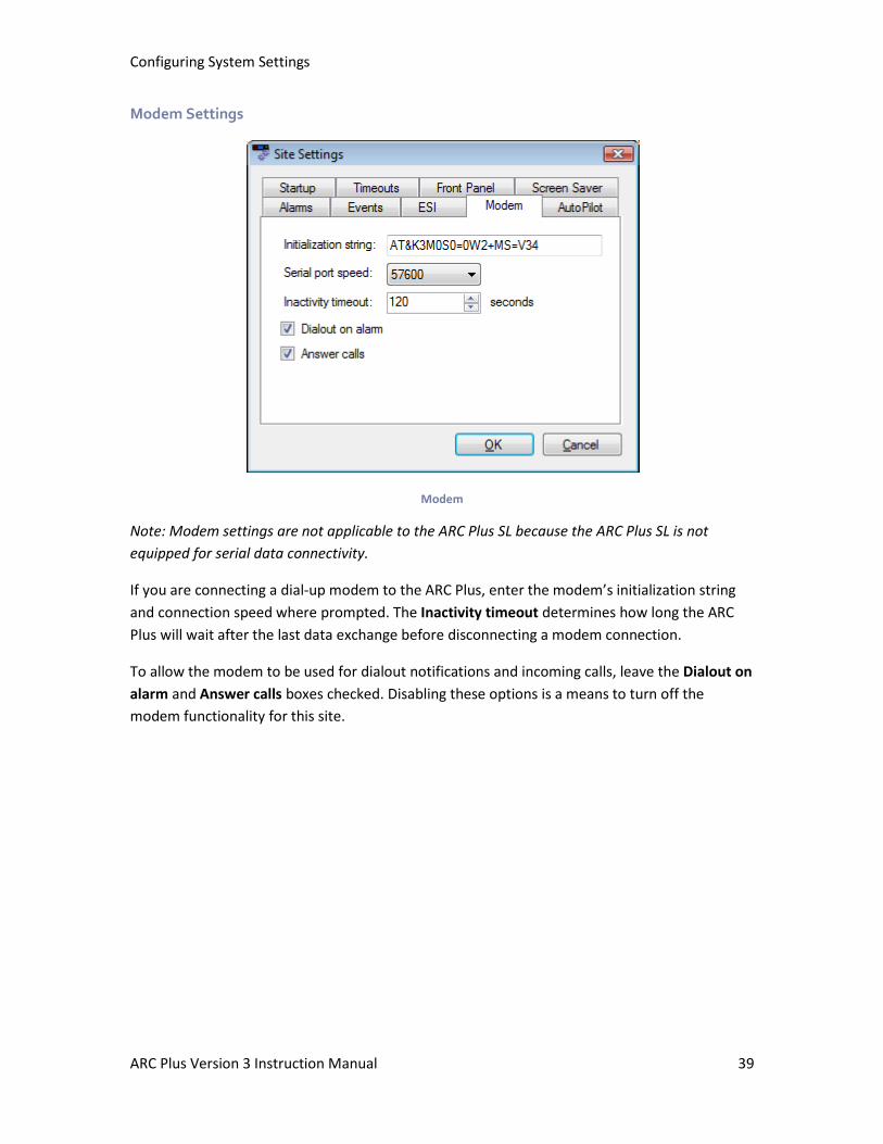
Configuring System Settings
ARC Plus Version 3 Instruction Manual 39
Modem Settings
Modem
Note: Modem settings are not applicable to the ARC Plus SL because the ARC Plus SL is not
equipped for serial data connectivity.
If you are connecting a dial-up modem to the ARC Plus, enter the modem’s initialization string
and connection speed where prompted. The Inactivity timeout determines how long the ARC
Plus will wait after the last data exchange before disconnecting a modem connection.
To allow the modem to be used for dialout notifications and incoming calls, leave the Dialout on
alarm and Answer calls boxes checked. Disabling these options is a means to turn off the
modem functionality for this site.

Configuring System Settings
ARC Plus Version 3 Instruction Manual 40
AutoPilot 2010 Authorization Code
AutoPilot
When you purchase a license for AutoPilot 2010, an authorization code is provided for one (1)
ARC Plus unit. Enter the authorization code where prompted in order to begin using AutoPilot
2010 with this ARC Plus.
Note: The ARC Plus will retain the authorization code after upgrading firmware, resetting factory
settings or cycling power. However, keeping a record of your authorization code is strongly
recommended.
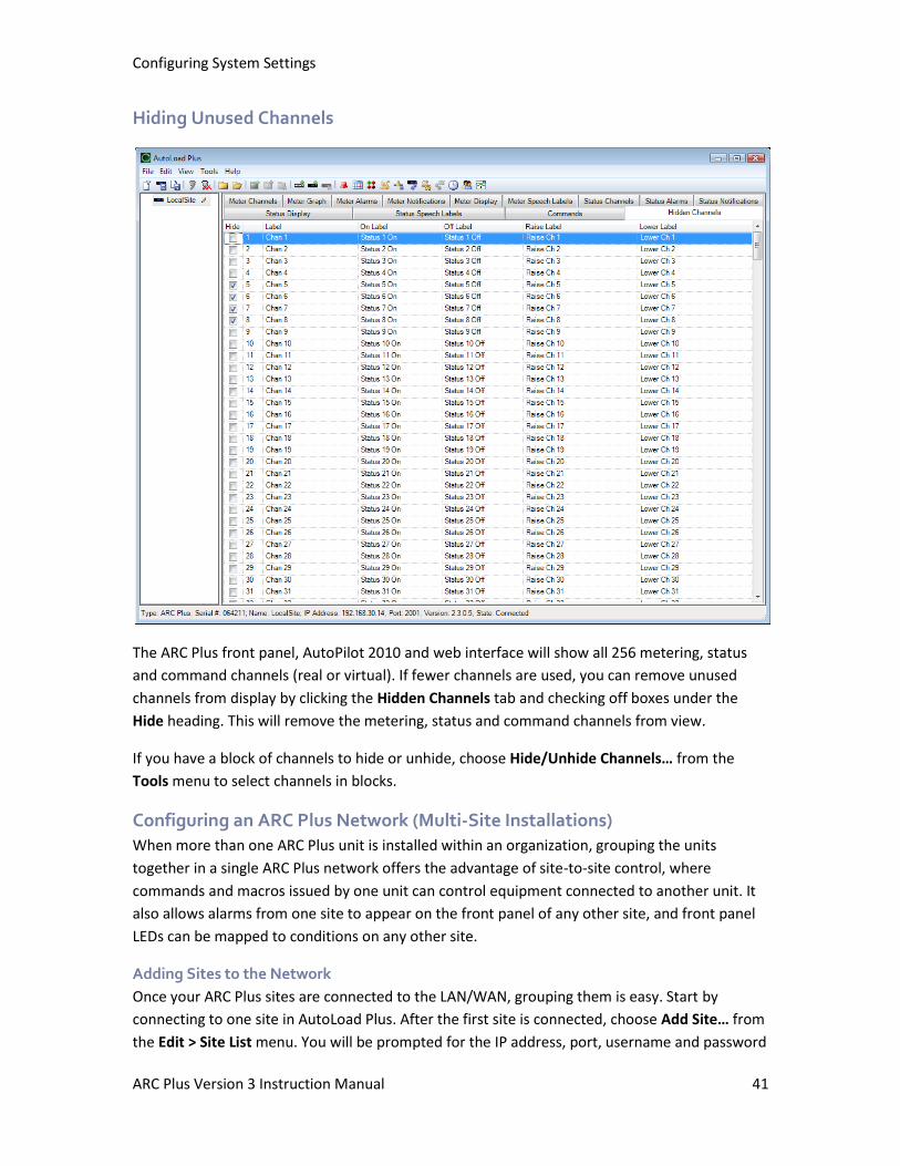
Configuring System Settings
ARC Plus Version 3 Instruction Manual 41
Hiding Unused Channels
The ARC Plus front panel, AutoPilot 2010 and web interface will show all 256 metering, status
and command channels (real or virtual). If fewer channels are used, you can remove unused
channels from display by clicking the Hidden Channels tab and checking off boxes under the
Hide heading. This will remove the metering, status and command channels from view.
If you have a block of channels to hide or unhide, choose Hide/Unhide Channels… from the
Tools menu to select channels in blocks.
Configuring an ARC Plus Network (Multi-Site Installations)
When more than one ARC Plus unit is installed within an organization, grouping the units
together in a single ARC Plus network offers the advantage of site-to-site control, where
commands and macros issued by one unit can control equipment connected to another unit. It
also allows alarms from one site to appear on the front panel of any other site, and front panel
LEDs can be mapped to conditions on any other site.
Adding Sites to the Network
Once your ARC Plus sites are connected to the LAN/WAN, grouping them is easy. Start by
connecting to one site in AutoLoad Plus. After the first site is connected, choose Add Site… from
the Edit > Site List menu. You will be prompted for the IP address, port, username and password
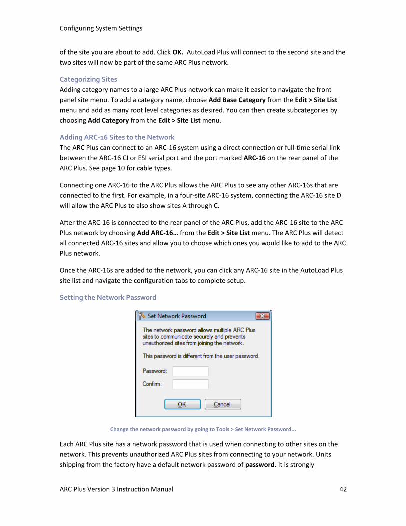
Configuring System Settings
ARC Plus Version 3 Instruction Manual 42
of the site you are about to add. Click OK. AutoLoad Plus will connect to the second site and the
two sites will now be part of the same ARC Plus network.
Categorizing Sites
Adding category names to a large ARC Plus network can make it easier to navigate the front
panel site menu. To add a category name, choose Add Base Category from the Edit > Site List
menu and add as many root level categories as desired. You can then create subcategories by
choosing Add Category from the Edit > Site List menu.
Adding ARC-16 Sites to the Network
The ARC Plus can connect to an ARC-16 system using a direct connection or full-time serial link
between the ARC-16 CI or ESI serial port and the port marked ARC-16 on the rear panel of the
ARC Plus. See page 10 for cable types.
Connecting one ARC-16 to the ARC Plus allows the ARC Plus to see any other ARC-16s that are
connected to the first. For example, in a four-site ARC-16 system, connecting the ARC-16 site D
will allow the ARC Plus to also show sites A through C.
After the ARC-16 is connected to the rear panel of the ARC Plus, add the ARC-16 site to the ARC
Plus network by choosing Add ARC-16… from the Edit > Site List menu. The ARC Plus will detect
all connected ARC-16 sites and allow you to choose which ones you would like to add to the ARC
Plus network.
Once the ARC-16s are added to the network, you can click any ARC-16 site in the AutoLoad Plus
site list and navigate the configuration tabs to complete setup.
Setting the Network Password
Change the network password by going to Tools > Set Network Password...
Each ARC Plus site has a network password that is used when connecting to other sites on the
network. This prevents unauthorized ARC Plus sites from connecting to your network. Units
shipping from the factory have a default network password of password. It is strongly
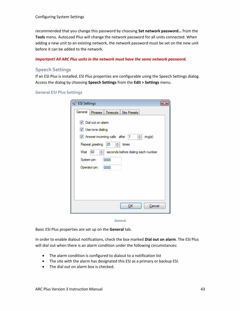
Configuring System Settings
ARC Plus Version 3 Instruction Manual 43
recommended that you change this password by choosing Set network password… from the
Tools menu. AutoLoad Plus will change the network password for all units connected. When
adding a new unit to an existing network, the network password must be set on the new unit
before it can be added to the network.
Important! All ARC Plus units in the network must have the same network password.
Speech Settings
If an ESI Plus is installed, ESI Plus properties are configurable using the Speech Settings dialog.
Access the dialog by choosing Speech Settings from the Edit > Settings menu.
General ESI Plus Settings
General
Basic ESI Plus properties are set up on the General tab.
In order to enable dialout notifications, check the box marked Dial out on alarm. The ESI Plus
will dial out when there is an alarm condition under the following circumstances:
• The alarm condition is configured to dialout to a notification list
• The site with the alarm has designated this ESI as a primary or backup ESI.
• The dial out on alarm box is checked.
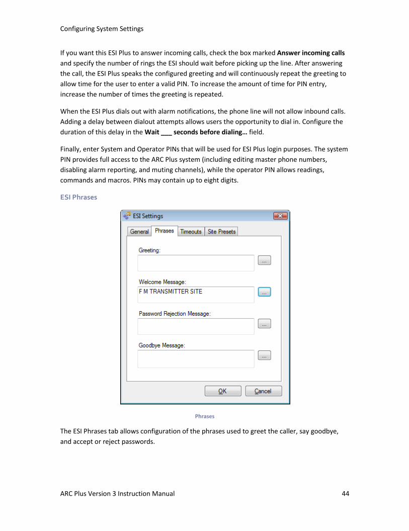
Configuring System Settings
ARC Plus Version 3 Instruction Manual 44
If you want this ESI Plus to answer incoming calls, check the box marked Answer incoming calls
and specify the number of rings the ESI should wait before picking up the line. After answering
the call, the ESI Plus speaks the configured greeting and will continuously repeat the greeting to
allow time for the user to enter a valid PIN. To increase the amount of time for PIN entry,
increase the number of times the greeting is repeated.
When the ESI Plus dials out with alarm notifications, the phone line will not allow inbound calls.
Adding a delay between dialout attempts allows users the opportunity to dial in. Configure the
duration of this delay in the Wait ___ seconds before dialing… field.
Finally, enter System and Operator PINs that will be used for ESI Plus login purposes. The system
PIN provides full access to the ARC Plus system (including editing master phone numbers,
disabling alarm reporting, and muting channels), while the operator PIN allows readings,
commands and macros. PINs may contain up to eight digits.
ESI Phrases
Phrases
The ESI Phrases tab allows configuration of the phrases used to greet the caller, say goodbye,
and accept or reject passwords.
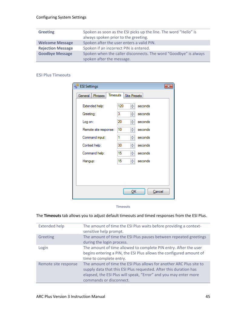
Configuring System Settings
ARC Plus Version 3 Instruction Manual 45
Greeting Spoken as soon as the ESI picks up the line. The word “Hello” is always spoken prior to the greeting.
Welcome Message Spoken after the user enters a valid PIN. Rejection Message Spoken if an incorrect PIN is entered. Goodbye Message Spoken when the caller disconnects. The word “Goodbye” is always
spoken after the message.
ESI Plus Timeouts
Timeouts
The Timeouts tab allows you to adjust default timeouts and timed responses from the ESI Plus.
Extended help The amount of time the ESI Plus waits before providing a context-sensitive help prompt.
Greeting The amount of time the ESI Plus pauses between repeated greetings during the login process.
Login The amount of time allowed to complete PIN entry. After the user begins entering a PIN, the ESI Plus allows the configured amount of time to complete entry.
Remote site response The amount of time the ESI Plus allows for another ARC Plus site to supply data that this ESI Plus requested. After this duration has elapsed, the ESI Plus will speak, “Error” and you may enter more commands or disconnect.
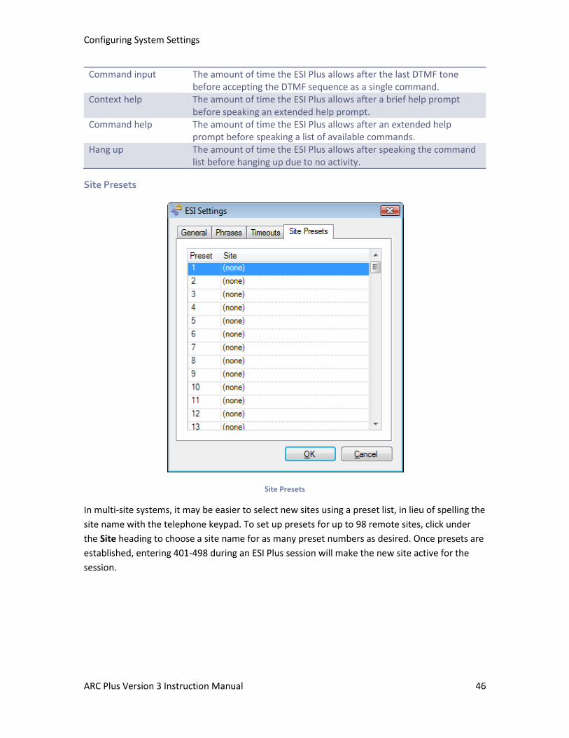
Configuring System Settings
ARC Plus Version 3 Instruction Manual 46
Command input The amount of time the ESI Plus allows after the last DTMF tone before accepting the DTMF sequence as a single command.
Context help The amount of time the ESI Plus allows after a brief help prompt before speaking an extended help prompt.
Command help The amount of time the ESI Plus allows after an extended help prompt before speaking a list of available commands.
Hang up
The amount of time the ESI Plus allows after speaking the command list before hanging up due to no activity.
Site Presets
Site Presets
In multi-site systems, it may be easier to select new sites using a preset list, in lieu of spelling the
site name with the telephone keypad. To set up presets for up to 98 remote sites, click under
the Site heading to choose a site name for as many preset numbers as desired. Once presets are
established, entering 401-498 during an ESI Plus session will make the new site active for the
session.
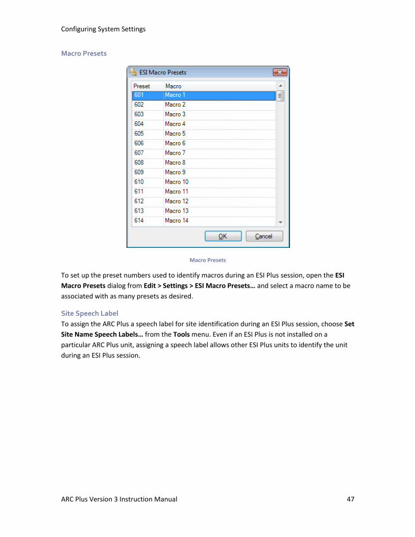
Configuring System Settings
ARC Plus Version 3 Instruction Manual 47
Macro Presets
Macro Presets
To set up the preset numbers used to identify macros during an ESI Plus session, open the ESI
Macro Presets dialog from Edit > Settings > ESI Macro Presets… and select a macro name to be
associated with as many presets as desired.
Site Speech Label
To assign the ARC Plus a speech label for site identification during an ESI Plus session, choose Set
Site Name Speech Labels… from the Tools menu. Even if an ESI Plus is not installed on a
particular ARC Plus unit, assigning a speech label allows other ESI Plus units to identify the unit
during an ESI Plus session.
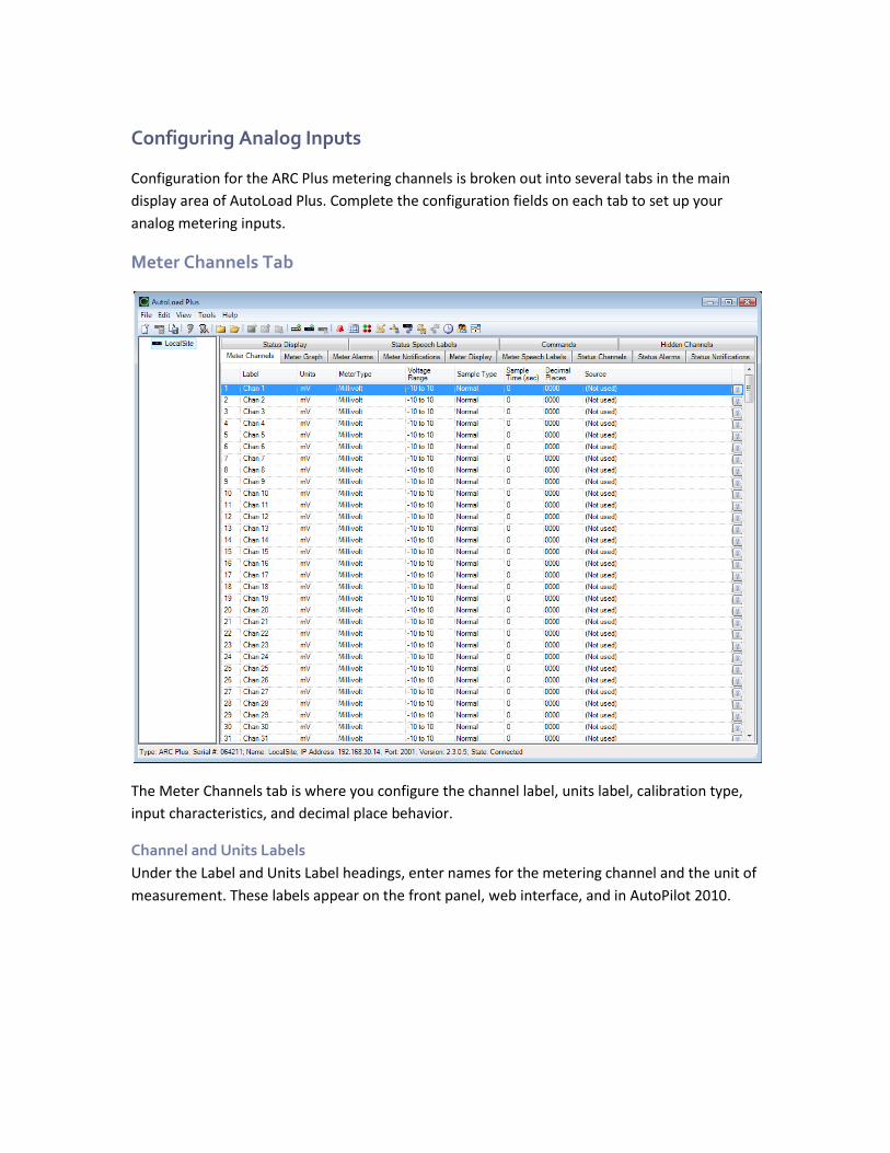
Configuring Analog Inputs
Configuration for the ARC Plus metering channels is broken out into several tabs in the main
display area of AutoLoad Plus. Complete the configuration fields on each tab to set up your
analog metering inputs.
Meter Channels Tab
The Meter Channels tab is where you configure the channel label, units label, calibration type,
input characteristics, and decimal place behavior.
Channel and Units Labels
Under the Label and Units Label headings, enter names for the metering channel and the unit of
measurement. These labels appear on the front panel, web interface, and in AutoPilot 2010.
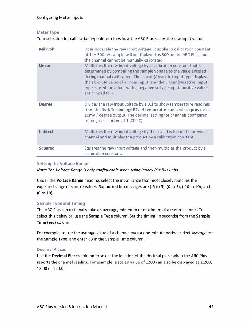
Configuring Meter Inputs
ARC Plus Version 3 Instruction Manual 49
Meter Type
Your selection for calibration type determines how the ARC Plus scales the raw input value:
Millivolt Does not scale the raw input voltage; it applies a calibration constant of 1. A 300mV sample will be displayed as 300 on the ARC Plus, and the channel cannot be manually calibrated.
Linear Multiplies the raw input voltage by a calibration constant that is determined by comparing the sample voltage to the value entered during manual calibration. The Linear (Absolute) input type displays the absolute value of a linear input, and the Linear (Negative) input type is used for values with a negative voltage input; positive values are clipped to 0.
Degree Divides the raw input voltage by a 0.1 to show temperature readings from the Burk Technology BTU-4 temperature unit, which provides a 10mV / degree output. The decimal setting for channels configured for degree is locked at 1 (000.0).
Indirect Multiplies the raw input voltage by the scaled value of the previous channel and multiples the product by a calibration constant.
Squared
Squares the raw input voltage and then multiples the product by a calibration constant.
Setting the Voltage Range
Note: The Voltage Range is only configurable when using legacy PlusBus units.
Under the Voltage Range heading, select the input range that most closely matches the
expected range of sample values. Supported input ranges are (-5 to 5), (0 to 5), (-10 to 10), and
(0 to 10).
Sample Type and Timing
The ARC Plus can optionally take an average, minimum or maximum of a meter channel. To
select this behavior, use the Sample Type column. Set the timing (in seconds) from the Sample
Time (sec) column.
For example, to use the average value of a channel over a one-minute period, select Average for
the Sample Type, and enter 60 in the Sample Time column.
Decimal Places
Use the Decimal Places column to select the location of the decimal place when the ARC Plus
reports the channel reading. For example, a scaled value of 1200 can also be displayed as 1.200,
12.00 or 120.0.
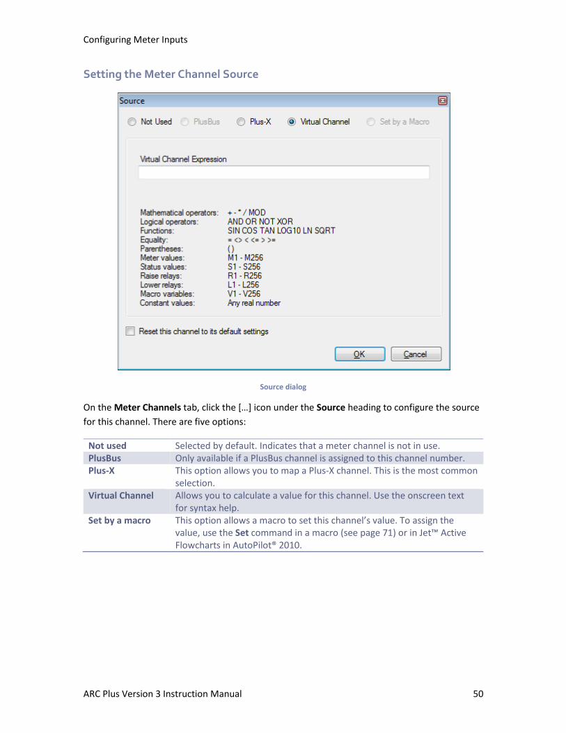
Configuring Meter Inputs
ARC Plus Version 3 Instruction Manual 50
Setting the Meter Channel Source
Source dialog
On the Meter Channels tab, click the […] icon under the Source heading to configure the source
for this channel. There are five options:
Not used Selected by default. Indicates that a meter channel is not in use. PlusBus Only available if a PlusBus channel is assigned to this channel number. Plus-X This option allows you to map a Plus-X channel. This is the most common
selection. Virtual Channel Allows you to calculate a value for this channel. Use the onscreen text
for syntax help. Set by a macro This option allows a macro to set this channel’s value. To assign the
value, use the Set command in a macro (see page 71) or in Jet™ Active Flowcharts in AutoPilot® 2010.
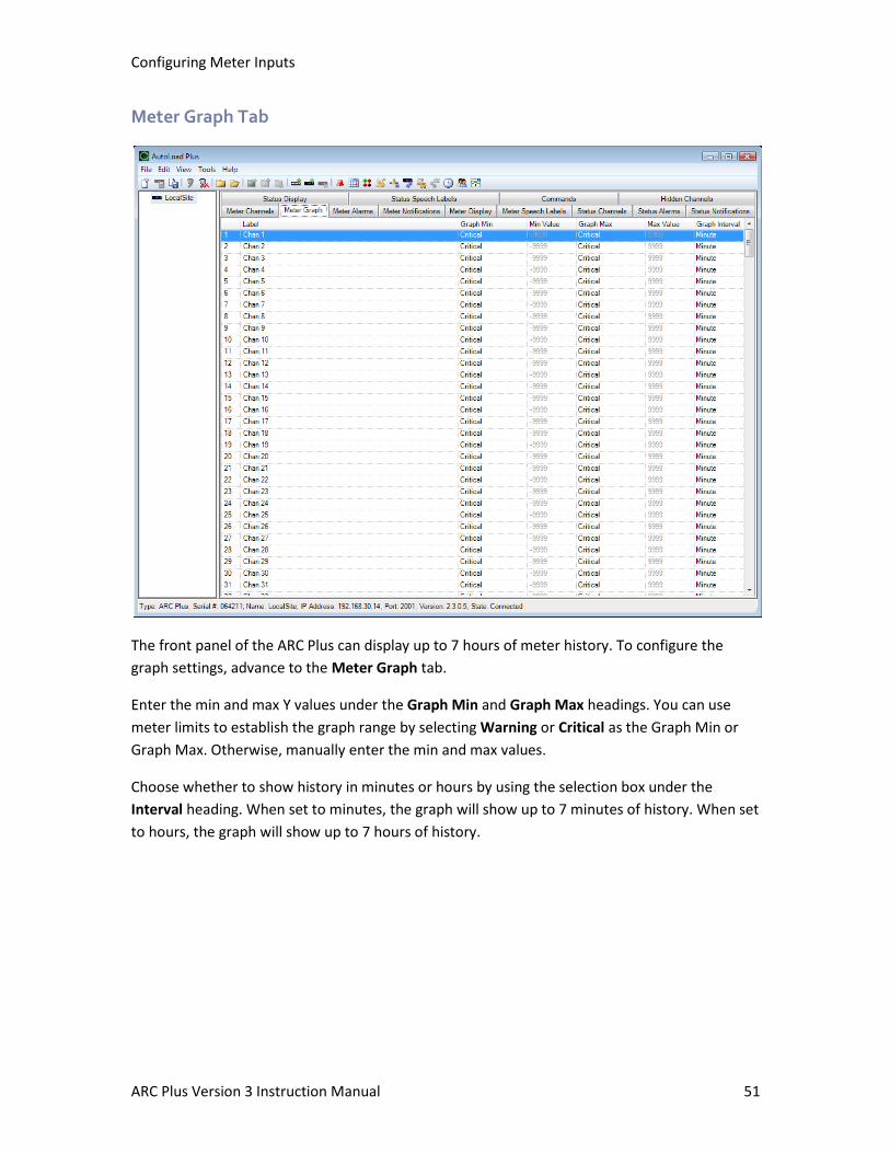
Configuring Meter Inputs
ARC Plus Version 3 Instruction Manual 51
Meter Graph Tab
The front panel of the ARC Plus can display up to 7 hours of meter history. To configure the
graph settings, advance to the Meter Graph tab.
Enter the min and max Y values under the Graph Min and Graph Max headings. You can use
meter limits to establish the graph range by selecting Warning or Critical as the Graph Min or
Graph Max. Otherwise, manually enter the min and max values.
Choose whether to show history in minutes or hours by using the selection box under the
Interval heading. When set to minutes, the graph will show up to 7 minutes of history. When set
to hours, the graph will show up to 7 hours of history.
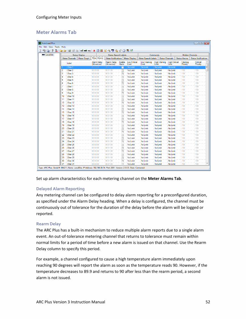
Configuring Meter Inputs
ARC Plus Version 3 Instruction Manual 52
Meter Alarms Tab
Set up alarm characteristics for each metering channel on the Meter Alarms Tab.
Delayed Alarm Reporting
Any metering channel can be configured to delay alarm reporting for a preconfigured duration,
as specified under the Alarm Delay heading. When a delay is configured, the channel must be
continuously out of tolerance for the duration of the delay before the alarm will be logged or
reported.
Rearm Delay
The ARC Plus has a built-in mechanism to reduce multiple alarm reports due to a single alarm
event. An out-of-tolerance metering channel that returns to tolerance must remain within
normal limits for a period of time before a new alarm is issued on that channel. Use the Rearm
Delay column to specify this period.
For example, a channel configured to cause a high temperature alarm immediately upon
reaching 90 degrees will report the alarm as soon as the temperature reads 90. However, if the
temperature decreases to 89.9 and returns to 90 after less than the rearm period, a second
alarm is not issued.
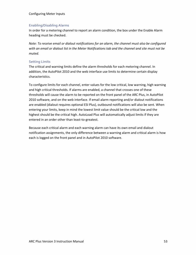
Configuring Meter Inputs
ARC Plus Version 3 Instruction Manual 53
Enabling/Disabling Alarms
In order for a metering channel to report an alarm condition, the box under the Enable Alarm
heading must be checked.
Note: To receive email or dialout notifications for an alarm, the channel must also be configured
with an email or dialout list in the Meter Notifications tab and the channel and site must not be
muted.
Setting Limits
The critical and warning limits define the alarm thresholds for each metering channel. In
addition, the AutoPilot 2010 and the web interface use limits to determine certain display
characteristics.
To configure limits for each channel, enter values for the low critical, low warning, high warning
and high critical thresholds. If alarms are enabled, a channel that crosses one of these
thresholds will cause the alarm to be reported on the front panel of the ARC Plus, in AutoPilot
2010 software, and on the web interface. If email alarm reporting and/or dialout notifications
are enabled (dialout requires optional ESI Plus), outbound notifications will also be sent. When
entering your limits, keep in mind the lowest limit value should be the critical low and the
highest should be the critical high. AutoLoad Plus will automatically adjust limits if they are
entered in an order other than least-to-greatest.
Because each critical alarm and each warning alarm can have its own email and dialout
notification assignments, the only difference between a warning alarm and critical alarm is how
each is logged on the front panel and in AutoPilot 2010 software.
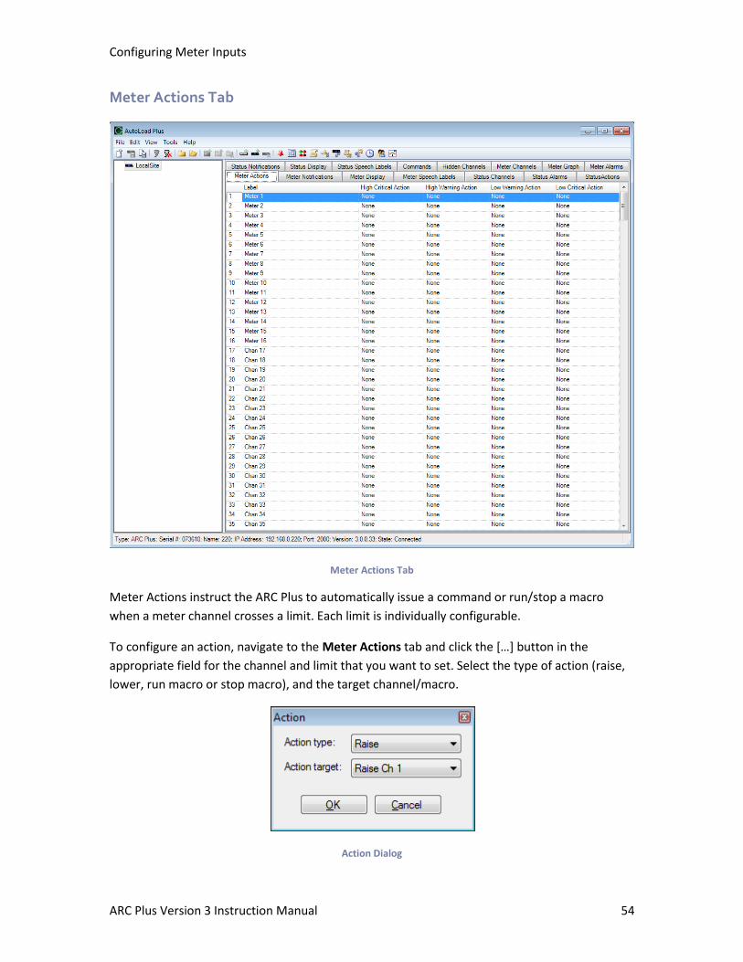
Configuring Meter Inputs
ARC Plus Version 3 Instruction Manual 54
Meter Actions Tab
Meter Actions Tab
Meter Actions instruct the ARC Plus to automatically issue a command or run/stop a macro
when a meter channel crosses a limit. Each limit is individually configurable.
To configure an action, navigate to the Meter Actions tab and click the […] button in the
appropriate field for the channel and limit that you want to set. Select the type of action (raise,
lower, run macro or stop macro), and the target channel/macro.
Action Dialog
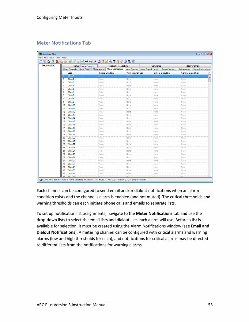
Configuring Meter Inputs
ARC Plus Version 3 Instruction Manual 55
Meter Notifications Tab
Each channel can be configured to send email and/or dialout notifications when an alarm
condition exists and the channel’s alarm is enabled (and not muted). The critical thresholds and
warning thresholds can each initiate phone calls and emails to separate lists.
To set up notification list assignments, navigate to the Meter Notifications tab and use the
drop-down lists to select the email lists and dialout lists each alarm will use. Before a list is
available for selection, it must be created using the Alarm Notifications window (see Email and
Dialout Notifications). A metering channel can be configured with critical alarms and warning
alarms (low and high thresholds for each), and notifications for critical alarms may be directed
to different lists from the notifications for warning alarms.
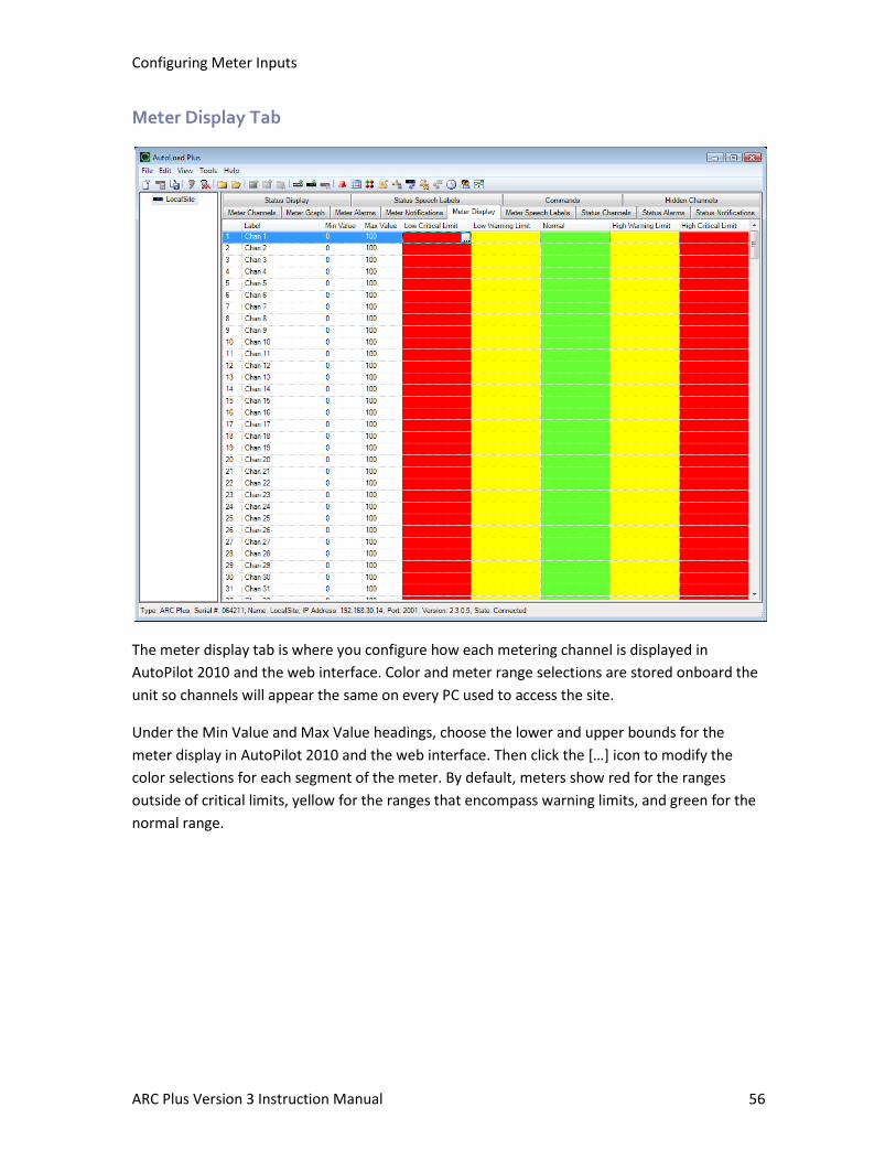
Configuring Meter Inputs
ARC Plus Version 3 Instruction Manual 56
Meter Display Tab
The meter display tab is where you configure how each metering channel is displayed in
AutoPilot 2010 and the web interface. Color and meter range selections are stored onboard the
unit so channels will appear the same on every PC used to access the site.
Under the Min Value and Max Value headings, choose the lower and upper bounds for the
meter display in AutoPilot 2010 and the web interface. Then click the […] icon to modify the
color selections for each segment of the meter. By default, meters show red for the ranges
outside of critical limits, yellow for the ranges that encompass warning limits, and green for the
normal range.
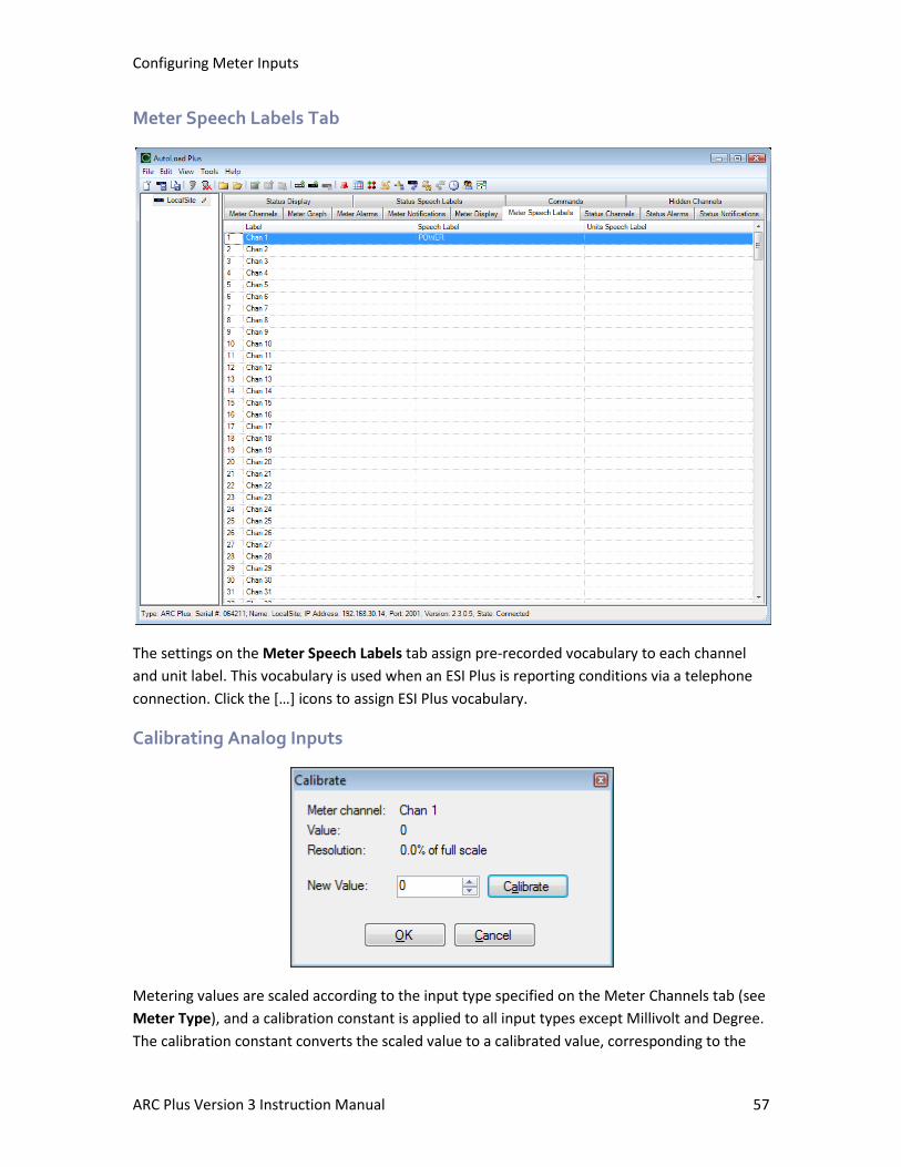
Configuring Meter Inputs
ARC Plus Version 3 Instruction Manual 57
Meter Speech Labels Tab
The settings on the Meter Speech Labels tab assign pre-recorded vocabulary to each channel
and unit label. This vocabulary is used when an ESI Plus is reporting conditions via a telephone
connection. Click the […] icons to assign ESI Plus vocabulary.
Calibrating Analog Inputs
Metering values are scaled according to the input type specified on the Meter Channels tab (see
Meter Type), and a calibration constant is applied to all input types except Millivolt and Degree.
The calibration constant converts the scaled value to a calibrated value, corresponding to the
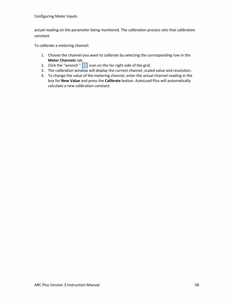
Configuring Meter Inputs
ARC Plus Version 3 Instruction Manual 58
actual reading on the parameter being monitored. The calibration process sets that calibration
constant.
To calibrate a metering channel:
1. Choose the channel you want to calibrate by selecting the corresponding row in the Meter Channels tab.
2. Click the “wrench ” icon on the far-right side of the grid. 3. The calibration window will display the current channel, scaled value and resolution. 4. To change the value of the metering channel, enter the actual channel reading in the
box for New Value and press the Calibrate button. AutoLoad Plus will automatically calculate a new calibration constant.
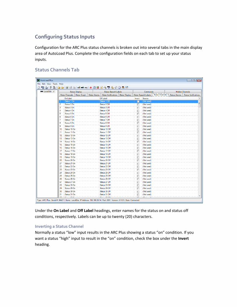
Configuring Status Inputs
Configuration for the ARC Plus status channels is broken out into several tabs in the main display
area of AutoLoad Plus. Complete the configuration fields on each tab to set up your status
inputs.
Status Channels Tab
Under the On Label and Off Label headings, enter names for the status on and status off
conditions, respectively. Labels can be up to twenty (20) characters.
Inverting a Status Channel
Normally a status “low” input results in the ARC Plus showing a status “on” condition. If you
want a status “high” input to result in the “on” condition, check the box under the Invert
heading.
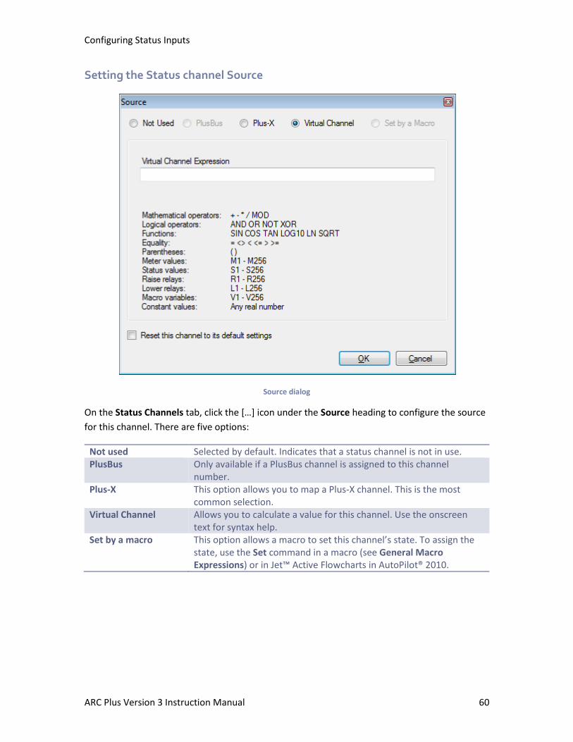
Configuring Status Inputs
ARC Plus Version 3 Instruction Manual 60
Setting the Status channel Source
Source dialog
On the Status Channels tab, click the […] icon under the Source heading to configure the source
for this channel. There are five options:
Not used Selected by default. Indicates that a status channel is not in use. PlusBus Only available if a PlusBus channel is assigned to this channel
number. Plus-X This option allows you to map a Plus-X channel. This is the most
common selection. Virtual Channel Allows you to calculate a value for this channel. Use the onscreen
text for syntax help. Set by a macro This option allows a macro to set this channel’s state. To assign the
state, use the Set command in a macro (see General Macro Expressions) or in Jet™ Active Flowcharts in AutoPilot® 2010.
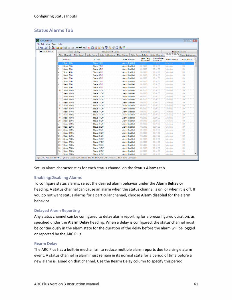
Configuring Status Inputs
ARC Plus Version 3 Instruction Manual 61
Status Alarms Tab
Set up alarm characteristics for each status channel on the Status Alarms tab.
Enabling/Disabling Alarms
To configure status alarms, select the desired alarm behavior under the Alarm Behavior
heading. A status channel can cause an alarm when the status channel is on, or when it is off. If
you do not want status alarms for a particular channel, choose Alarm disabled for the alarm
behavior.
Delayed Alarm Reporting
Any status channel can be configured to delay alarm reporting for a preconfigured duration, as
specified under the Alarm Delay heading. When a delay is configured, the status channel must
be continuously in the alarm state for the duration of the delay before the alarm will be logged
or reported by the ARC Plus.
Rearm Delay
The ARC Plus has a built-in mechanism to reduce multiple alarm reports due to a single alarm
event. A status channel in alarm must remain in its normal state for a period of time before a
new alarm is issued on that channel. Use the Rearm Delay column to specify this period.

Configuring Status Inputs
ARC Plus Version 3 Instruction Manual 62
Setting the Alarm Severity
Status alarms may be configured as warning alarms or critical alarms. Both types of alarms are
reported in the same ways (front panel, email notifications, dial out behavior, etc.). The
designation as warning or critical simply aids in prioritizing alarm response or reviewing past
alarm activity.
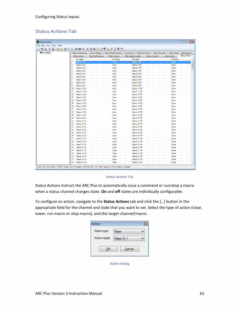
Configuring Status Inputs
ARC Plus Version 3 Instruction Manual 63
Status Actions Tab
Status Actions Tab
Status Actions instruct the ARC Plus to automatically issue a command or run/stop a macro
when a status channel changes state. On and off states are individually configurable.
To configure an action, navigate to the Status Actions tab and click the […] button in the
appropriate field for the channel and state that you want to set. Select the type of action (raise,
lower, run macro or stop macro), and the target channel/macro.
Action Dialog
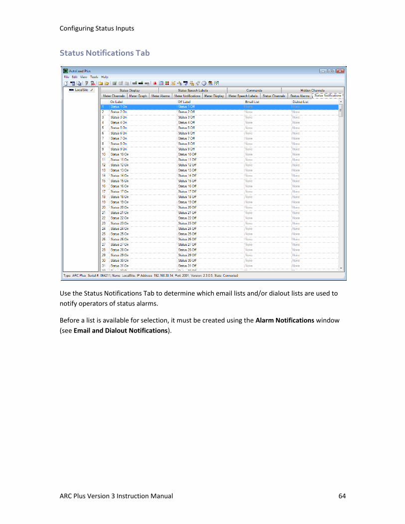
Configuring Status Inputs
ARC Plus Version 3 Instruction Manual 64
Status Notifications Tab
Use the Status Notifications Tab to determine which email lists and/or dialout lists are used to
notify operators of status alarms.
Before a list is available for selection, it must be created using the Alarm Notifications window
(see Email and Dialout Notifications).
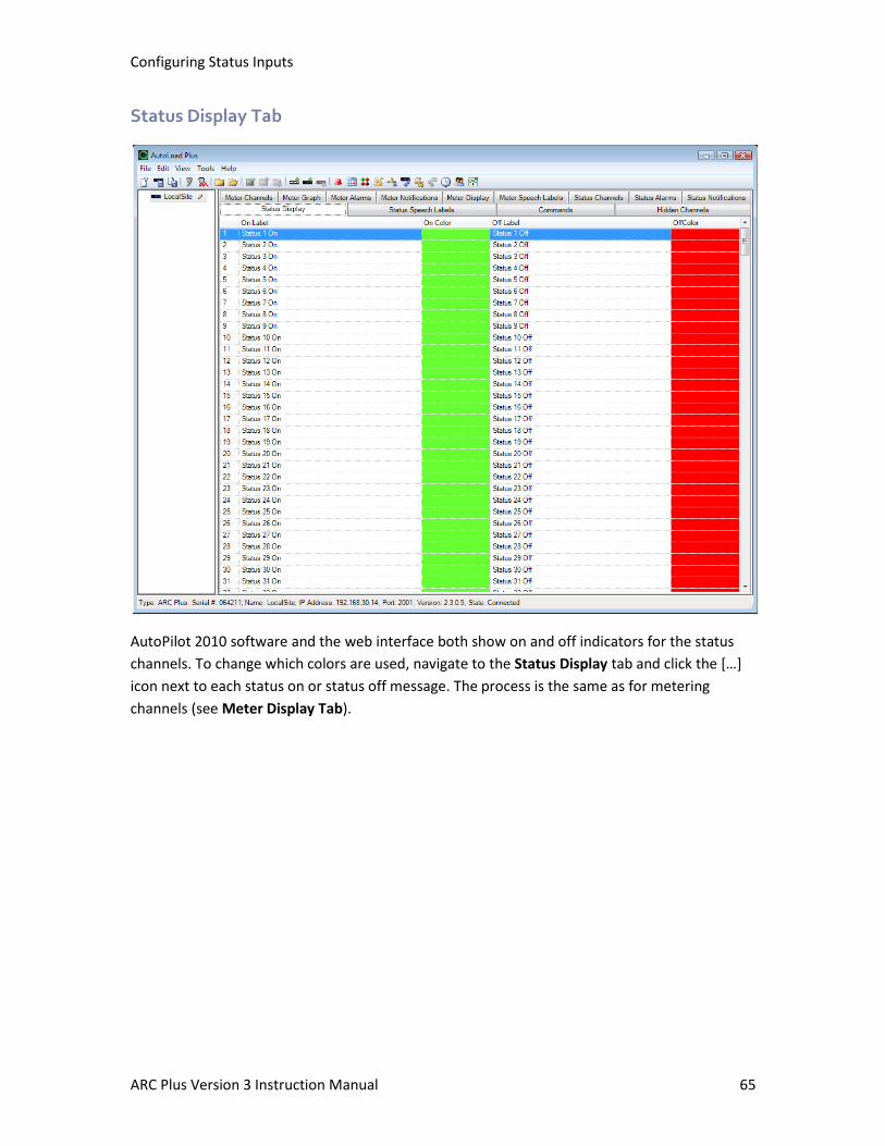
Configuring Status Inputs
ARC Plus Version 3 Instruction Manual 65
Status Display Tab
AutoPilot 2010 software and the web interface both show on and off indicators for the status
channels. To change which colors are used, navigate to the Status Display tab and click the […]
icon next to each status on or status off message. The process is the same as for metering
channels (see Meter Display Tab).
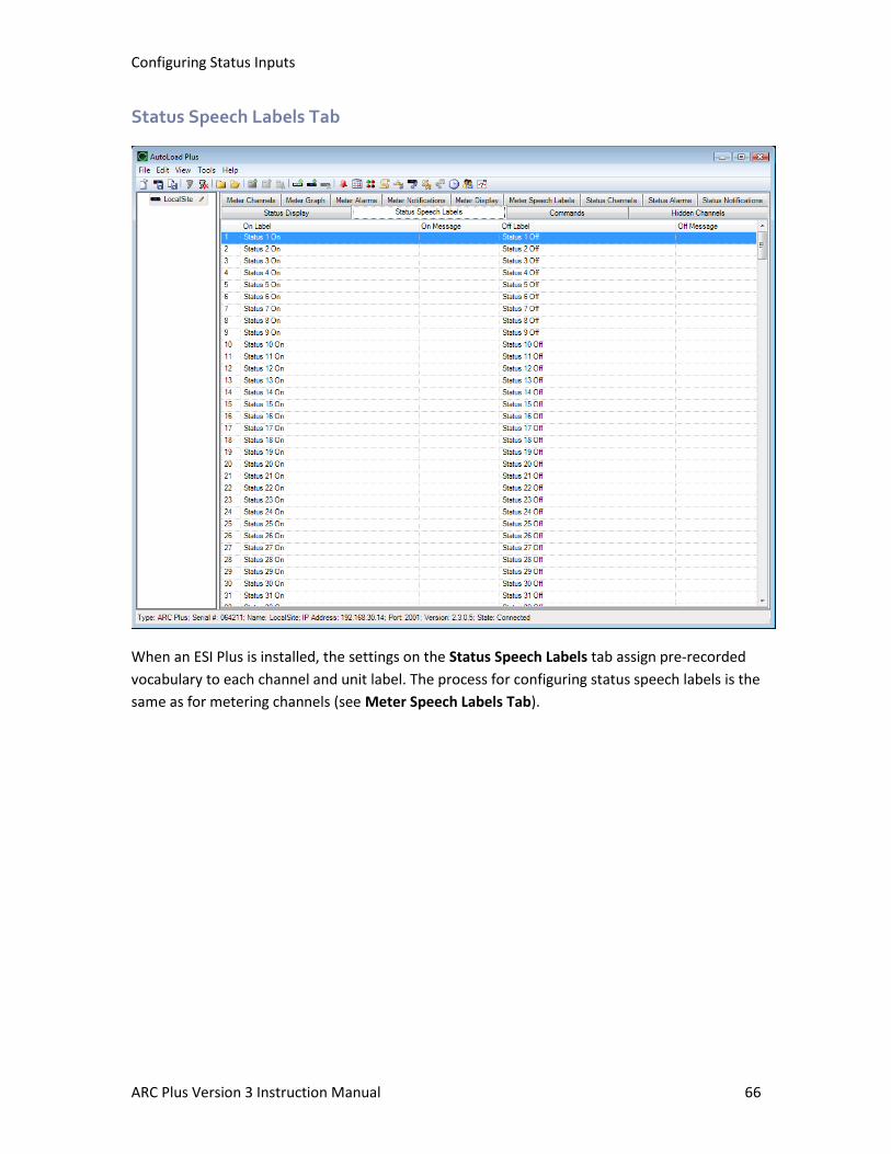
Configuring Status Inputs
ARC Plus Version 3 Instruction Manual 66
Status Speech Labels Tab
When an ESI Plus is installed, the settings on the Status Speech Labels tab assign pre-recorded
vocabulary to each channel and unit label. The process for configuring status speech labels is the
same as for metering channels (see Meter Speech Labels Tab).
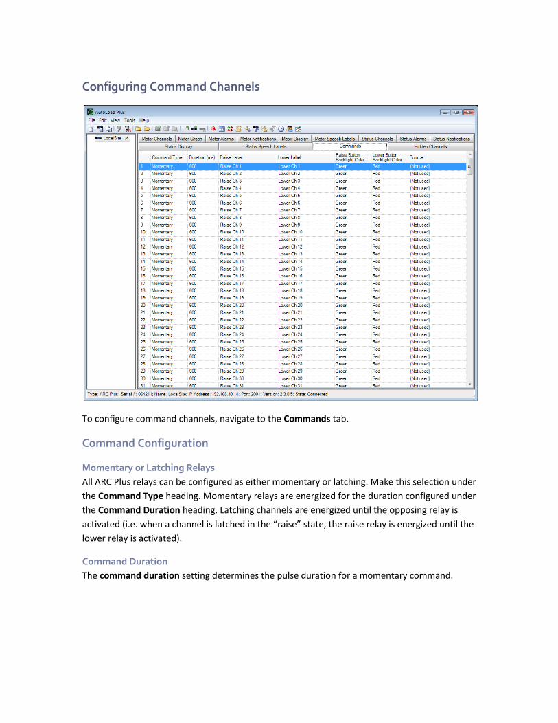
Configuring Command Channels
To configure command channels, navigate to the Commands tab.
Command Configuration
Momentary or Latching Relays
All ARC Plus relays can be configured as either momentary or latching. Make this selection under
the Command Type heading. Momentary relays are energized for the duration configured under
the Command Duration heading. Latching channels are energized until the opposing relay is
activated (i.e. when a channel is latched in the “raise” state, the raise relay is energized until the
lower relay is activated).
Command Duration
The command duration setting determines the pulse duration for a momentary command.
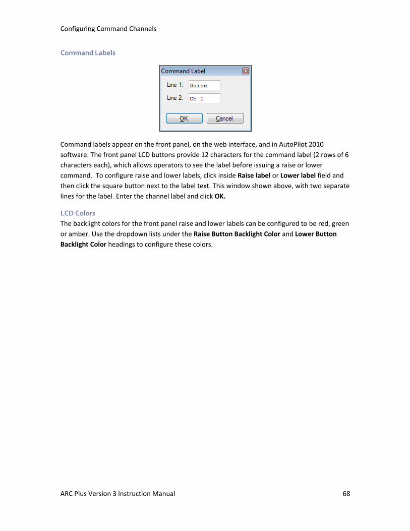
Configuring Command Channels
ARC Plus Version 3 Instruction Manual 68
Command Labels
Command labels appear on the front panel, on the web interface, and in AutoPilot 2010
software. The front panel LCD buttons provide 12 characters for the command label (2 rows of 6
characters each), which allows operators to see the label before issuing a raise or lower
command. To configure raise and lower labels, click inside Raise label or Lower label field and
then click the square button next to the label text. This window shown above, with two separate
lines for the label. Enter the channel label and click OK.
LCD Colors
The backlight colors for the front panel raise and lower labels can be configured to be red, green
or amber. Use the dropdown lists under the Raise Button Backlight Color and Lower Button
Backlight Color headings to configure these colors.
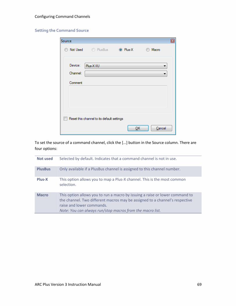
Configuring Command Channels
ARC Plus Version 3 Instruction Manual 69
Setting the Command Source
To set the source of a command channel, click the […] button in the Source column. There are
four options:
Not used Selected by default. Indicates that a command channel is not in use.
PlusBus Only available if a PlusBus channel is assigned to this channel number.
Plus-X This option allows you to map a Plus-X channel. This is the most common selection.
Macro This option allows you to run a macro by issuing a raise or lower command to the channel. Two different macros may be assigned to a channel’s respective raise and lower commands. Note: You can always run/stop macros from the macro list.
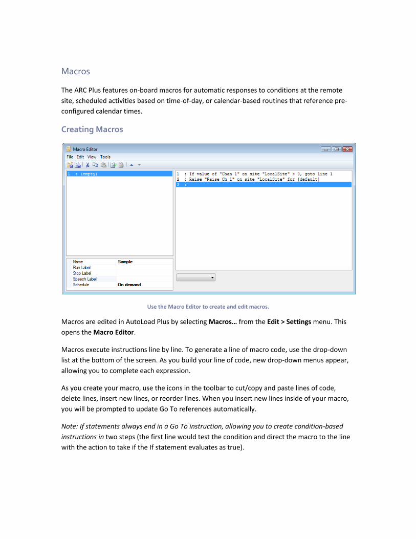
Macros
The ARC Plus features on-board macros for automatic responses to conditions at the remote
site, scheduled activities based on time-of-day, or calendar-based routines that reference pre-
configured calendar times.
Creating Macros
Use the Macro Editor to create and edit macros.
Macros are edited in AutoLoad Plus by selecting Macros… from the Edit > Settings menu. This
opens the Macro Editor.
Macros execute instructions line by line. To generate a line of macro code, use the drop-down
list at the bottom of the screen. As you build your line of code, new drop-down menus appear,
allowing you to complete each expression.
As you create your macro, use the icons in the toolbar to cut/copy and paste lines of code,
delete lines, insert new lines, or reorder lines. When you insert new lines inside of your macro,
you will be prompted to update Go To references automatically.
Note: If statements always end in a Go To instruction, allowing you to create condition-based
instructions in two steps (the first line would test the condition and direct the macro to the line
with the action to take if the If statement evaluates as true).

Macros
ARC Plus Version 3 Instruction Manual 71
General Macro Expressions
If The “If” macro command is a versatile way to compare two values in a macro. The types of values are: meter value, status value, macro variable and constant. To use this command, select the type of value for each side of the equation using the drop down lists, and pick the operator you want to use for comparison (=, <>, <, >).
Set The “Set” macro command allows you to set a meter channel, status channel or macro variable to any of the following: meter channel, status channel, macro variable or constant. For example, if your antenna monitor readings appear on channel 10, and you want to store the current reading on channel 11, you can set channel 11 to the value of channel 10. Note: Channels that are configured to be “set by a macro” are only updated when the macro assigns their new value.
Macro Expressions for Channel Values and Site Conditions
Use these functions for expressions that read channel values and site conditions from the ARC
Plus:
If Value If Status
These statements test the expression against the most recently obtained meter/status value for the specified site and channel.
If New Value If New Status
This statement waits until the ARC Plus updates the meter/status reading before testing the expression against the value. Use this macro function to test the result of a raise/lower command.
If Relay State Tests if the state of a relay is latched or unlatched. If Alarm Tests the expression against the alarm count at the specified site. Can
be used with an inequality to trigger an action if the alarm count is greater than 0.
If Maint Mode Tests the expression against the maintenance mode on/off state at the specified site.
Raise/Lower Issues a command to the specified site and channel. Note that the command duration entered in the macro editor will override the command duration otherwise programmed for the channel.
Alarm Generates an alarm on the ARC Plus with the specified message. Can also be used at the end of a macro to initiate notification that the macro is complete.
Set Mute Mutes alarm reporting on the specified channel. Set Limit Sets a meter channel limit value. This is typically used to change power
limits on AM stations that run with different day/night power.
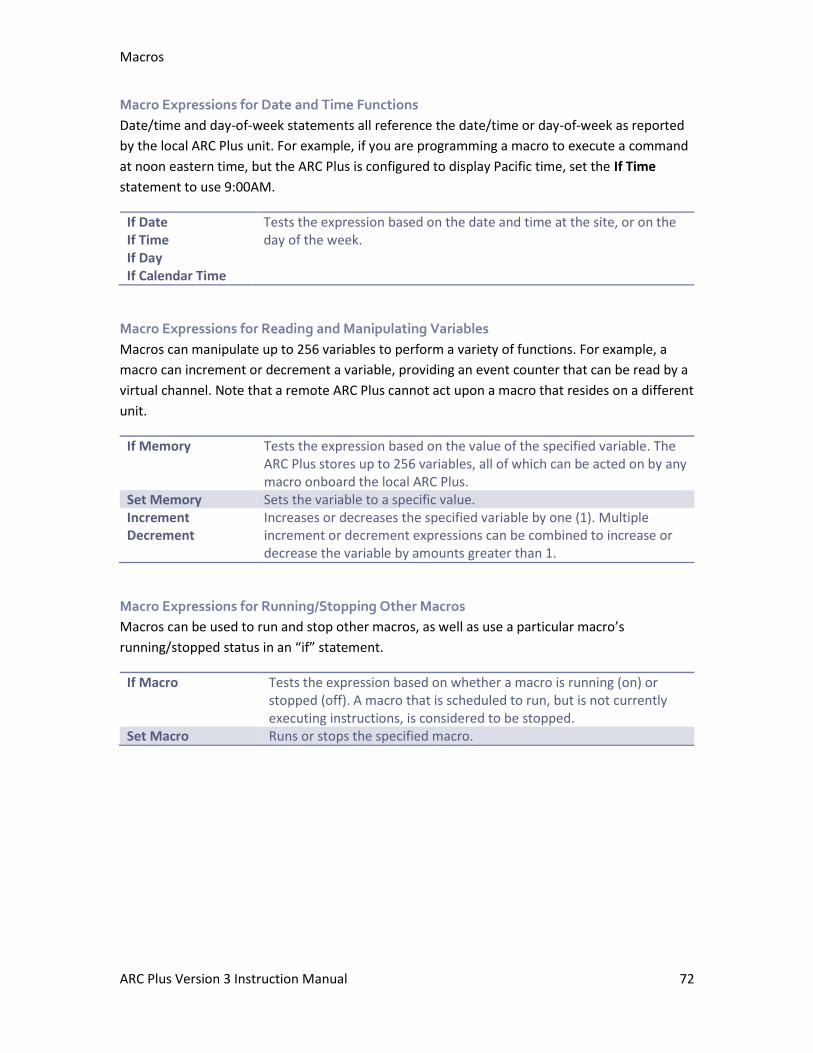
Macros
ARC Plus Version 3 Instruction Manual 72
Macro Expressions for Date and Time Functions
Date/time and day-of-week statements all reference the date/time or day-of-week as reported
by the local ARC Plus unit. For example, if you are programming a macro to execute a command
at noon eastern time, but the ARC Plus is configured to display Pacific time, set the If Time
statement to use 9:00AM.
If Date If Time If Day If Calendar Time
Tests the expression based on the date and time at the site, or on the day of the week.
Macro Expressions for Reading and Manipulating Variables
Macros can manipulate up to 256 variables to perform a variety of functions. For example, a
macro can increment or decrement a variable, providing an event counter that can be read by a
virtual channel. Note that a remote ARC Plus cannot act upon a macro that resides on a different
unit.
If Memory Tests the expression based on the value of the specified variable. The ARC Plus stores up to 256 variables, all of which can be acted on by any macro onboard the local ARC Plus.
Set Memory Sets the variable to a specific value. Increment Decrement
Increases or decreases the specified variable by one (1). Multiple increment or decrement expressions can be combined to increase or decrease the variable by amounts greater than 1.
Macro Expressions for Running/Stopping Other Macros
Macros can be used to run and stop other macros, as well as use a particular macro’s
running/stopped status in an “if” statement.
If Macro Tests the expression based on whether a macro is running (on) or stopped (off). A macro that is scheduled to run, but is not currently executing instructions, is considered to be stopped.
Set Macro Runs or stops the specified macro.
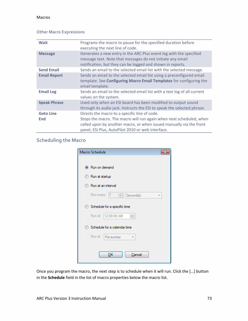
Macros
ARC Plus Version 3 Instruction Manual 73
Other Macro Expressions
Wait Programs the macro to pause for the specified duration before executing the next line of code.
Message Generates a new entry in the ARC Plus event log with the specified message text. Note that messages do not initiate any email notification, but they can be logged and shown in reports.
Send Email Sends an email to the selected email list with the selected message. Email Report Sends an email to the selected email list using a preconfigured email
template. See Configuring Macro Email Templates for configuring the email template.
Email Log Sends an email to the selected email list with a text log of all current values on the system.
Speak Phrase Used only when an ESI board has been modified to output sound through its audio jack. Instructs the ESI to speak the selected phrase.
Goto Line Directs the macro to a specific line of code. End Stops the macro. The macro will run again when next scheduled, when
called upon by another macro, or when issued manually via the front panel, ESI Plus, AutoPilot 2010 or web interface.
Scheduling the Macro
Once you program the macro, the next step is to schedule when it will run. Click the […] button
in the Schedule field in the list of macro properties below the macro list.
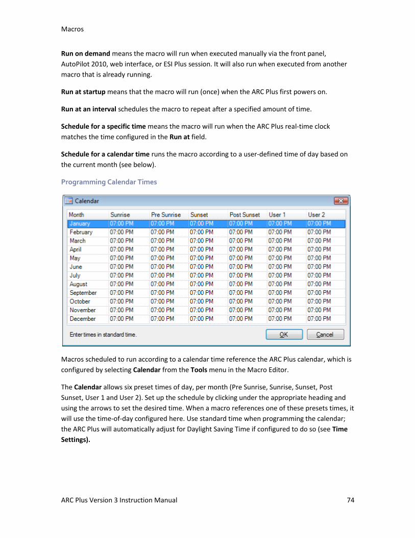
Macros
ARC Plus Version 3 Instruction Manual 74
Run on demand means the macro will run when executed manually via the front panel,
AutoPilot 2010, web interface, or ESI Plus session. It will also run when executed from another
macro that is already running.
Run at startup means that the macro will run (once) when the ARC Plus first powers on.
Run at an interval schedules the macro to repeat after a specified amount of time.
Schedule for a specific time means the macro will run when the ARC Plus real-time clock
matches the time configured in the Run at field.
Schedule for a calendar time runs the macro according to a user-defined time of day based on
the current month (see below).
Programming Calendar Times
Macros scheduled to run according to a calendar time reference the ARC Plus calendar, which is
configured by selecting Calendar from the Tools menu in the Macro Editor.
The Calendar allows six preset times of day, per month (Pre Sunrise, Sunrise, Sunset, Post
Sunset, User 1 and User 2). Set up the schedule by clicking under the appropriate heading and
using the arrows to set the desired time. When a macro references one of these presets times, it
will use the time-of-day configured here. Use standard time when programming the calendar;
the ARC Plus will automatically adjust for Daylight Saving Time if configured to do so (see Time
Settings).
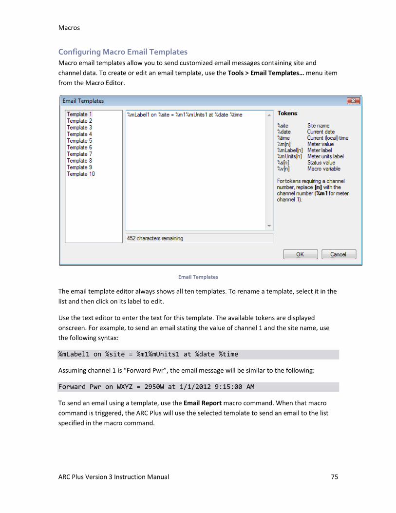
Macros
ARC Plus Version 3 Instruction Manual 75
Configuring Macro Email Templates
Macro email templates allow you to send customized email messages containing site and
channel data. To create or edit an email template, use the Tools > Email Templates… menu item
from the Macro Editor.
Email Templates
The email template editor always shows all ten templates. To rename a template, select it in the
list and then click on its label to edit.
Use the text editor to enter the text for this template. The available tokens are displayed
onscreen. For example, to send an email stating the value of channel 1 and the site name, use
the following syntax:
%mLabel1 on %site = %m1%mUnits1 at %date %time
Assuming channel 1 is “Forward Pwr”, the email message will be similar to the following:
Forward Pwr on WXYZ = 2950W at 1/1/2012 9:15:00 AM
To send an email using a template, use the Email Report macro command. When that macro
command is triggered, the ARC Plus will use the selected template to send an email to the list
specified in the macro command.
Macros
ARC Plus Version 3 Instruction Manual 76
Saving and Naming the Macro
Macro Name
Set a name for your macro by entering in the Name field in the macro properties list.
Run Label and Stop Label
While the front panel macro menu displays the name of the macro, the LCD buttons used to run
and stop the macro can be programmed to display specific run and stop labels. By default, these
labels are Run Macro and Stop Macro. If desired, you can change these labels by entering text in
the Run Label and Stop Label fields in the macro properties list.
Speech Label
In order for an ESI Plus speech interface to report the name of the macro, a label must be
assigned in the Speech Label field.
Front Panel Operation
The front panel controls on the ARC Plus allow operators to monitor and control any site in the
network (allowing control of studio equipment from a transmitter site, for example), as well as
configure some of the settings that are also accessible in AutoLoad Plus software. It is generally
easier to configure the system using AutoLoad Plus; front panel configuration provides
convenient on-the-fly changes.
Commands and configuration changes are effective for the unit that is selected for display on
the front panel of the ARC Plus. The currently selected site is always displayed in the upper left
corner of the screen. If you select a remote site for display, commands and configuration
changes will be sent to the remote unit. Other units may need to reselect the site or channel to
see configuration updates, such as a change to a channel label.
Menu navigation
Front panel menus are operated by rotating the jog wheel to the desired item and pressing the
jog wheel to activate the selection. The ARC Plus has a user-configurable screen saver option
(see page 35). If the front panel is dim or blank, rotate the jog wheel to restore the screen to its
normal state. To cancel a menu selection and return to the top level, press and hold the jog
wheel for a few seconds.
The instructions below use the > symbol to separate menu levels. For example, metering
channel calibration is accomplished by accessing the Config menu, selecting Channel, followed
by Metering and finally Calib. This would appear in the instructions as Config > Channel >
Metering > Calib. For a quick reference of the entire front panel menu structure, see Appendix
E: Menu Diagram).
Selecting Sites and Channels for Display
Selecting Sites
The top-level Site menu allows site selection for site-to-site monitoring and control. Select this
menu to display a list of sites in the system. If you have grouped sites and added category
names, your site hierarchy structure will appear in the site list. Select the desired site for display.
Once selected, the site name appears at the top left of the screen and commands and readings
are valid for the selected site.
Changing Channels
After selecting a site, rotate the jog wheel to change which channel is displayed. Hidden
channels are not available for selection.
Front Panel Operation
ARC Plus Version 3 Instruction Manual 78
Toggling Between Text and Graph Mode
Metering channels can be displayed in two different ways: text mode and graph mode. Text
mode provides a real-time text readout of the channel reading. In graph mode, the ARC Plus
tracks readings over time (for as long as the channel is selected) and displays them in graph
format. To toggle between text and graph mode, navigate to View > Graph or View > Text as
appropriate.
Note: You can edit the graph display settings in AutoLoad Plus (see Meter Graph Tab).
Viewing Status Conditions
The ARC Plus displays status conditions using the front panel LED indicators, as well as in the on-
screen status report. The 16 LED indicators can be mapped to any site or channel and can also
indicate other site conditions (see Mapping the Front Panel LEDs).
To view the status report on the front panel, navigate to View > Status. The status report shows
Status ON conditions by default, but can be configured to show Status OFF conditions as well
(see Front Panel Behavior).
Issuing Commands
The command buttons on the right side of the front panel allow you to issue raise and lower
commands to the associated channel. As you select each channel using the jog wheel, the labels
for the command buttons are updated. These labels and the background color for the command
buttons are configured using the AutoLoad Plus software (see Command Labels).
Pushing a command button executes the raise or lower command. For momentary commands,
reissuing a command while the command output is still active restarts the command duration
timer (in other words, the ARC Plus does not wait for the first command to finish before starting
the second command).
Note that the command duration is configured in AutoLoad Plus (see Command Duration).
Pressing and holding the command button does not extend the command duration.
Note: It is possible to override command button functionality so that the command button issues
a macro instead of executing a raise/lower command. See Setting the Command Source for
more on overriding command channels.
Running Macros
To run macros, or to see which macros are already running, select Macros from the top menu
level. The macro list appears, showing which macros are already running. Use the jog wheel to
select the desired macro. To run or stop the macro, use the command buttons on the right side
of the front panel.
When you are done with macros, push the jog wheel once to return to the main display.

Front Panel Operation
ARC Plus Version 3 Instruction Manual 79
To run macros directly from the channel display (without selecting the Macros menu), use
AutoLoad Plus to override an unused command channel with the macro functionality.
Viewing Alarms
The front panel alarm LED alerts users to the presence of an alarm, either at the local site, or at
any other site in the network. You can define this behavior in AutoLoad Plus (see Alarms).
To view and clear alarms, navigate to View > Alarms. The ARC Plus displays a list of sites with
active alarms, with the local site at the top of the list whether there is an alarm or not. Any sites
missing from the list have no active alarms.
Select the desired site to see a list of alarms at that site. Up to 256 alarms are shown. The ARC
Plus displays active alarms first, followed by cleared alarms that are stored in memory. Critical
alarms are flagged with the (!) icon. Cleared alarms are flagged with the (X) icon. Once 256
alarms are stored in memory, the oldest cleared alarm is deleted to make room for a new active
alarm. The only time an active alarm would be removed from memory is if there are already 256
active alarms and a new one occurs.
Select any alarm in the list to view the date/time of the alarm, the type of the alarm, and when
the alarm was cleared (if applicable).
To clear an alarm, select it from the alarm list and then select Clear Alarm. To clear all alarms at
the site, select Clear All. When you clear an alarm, it will no longer be reported as an out of
tolerance condition from the front panel of any ARC Plus unit, via AutoPilot 2010, or via the ESI
Plus.
Reviewing Events
The ARC Plus keeps a record of the 256 most recent events, such as IIU or ICRU
connections/interruptions; TCP/IP sessions, etc. To view the event list, navigate to View >
Events. Once 256 events are stored, the oldest will be deleted to make room for a new one.
Using Maintenance Mode
Maintenance mode disables all ARC Plus commands, regardless of origin, making it possible to
perform maintenance on site equipment without the risk of ARC Plus command actuation.
Maintenance mode can only be enabled or disabled from the front panel of the local unit; it
cannot be toggled remotely by any means.
To turn maintenance mode on, select MAINT from the top menu level. The display will prompt
you to select ON or OFF. Turn maintenance mode ON to disable commands, or OFF to enable
them. The MAINT flag appears on the front panel and the REMOTE LED turns red when the site
is in maintenance mode. If you select a different site for display, the MAINT flag disappears, but
the red REMOTE LED remains illuminated.
Front Panel Operation
ARC Plus Version 3 Instruction Manual 80
Macros will continue to run while a unit is in maintenance mode. However, any commands
driven by macros will not be issued. The If Maint Mode macro command can be used to test
maintenance mode status (see General Macro Expressions).
Channel Configuration
The Channel Configuration menu is where you configure settings that affect how the ARC Plus
displays and processes channel data, such as which channels have alarms enabled or disabled,
metering and status channel limits, command durations, etc.
From the top level of the menus, access the channel menu by navigating to Config > Channel.
Enabling/Disabling Alarms
The Alarms submenu allows you to determine which channels trigger alarm conditions when
they are outside of their prescribed tolerances. The menu allows you to enable/disable alarms
on all channels or on specific metering and status channels. If you disable all alarms, enabling
them again will only enable alarms that were enabled prior to disabling.
Adjusting Metering Limits
To adjust metering channel limits, navigate to Config > Channel > Metering > Limits and select
the desired metering channel. Use the jog wheel to enter the desired values for each limit
threshold. If you do not want the ARC Plus to report an alarm for one or more thresholds, set
the limit to 9999 or -9999 to disable it.
Note: The front panel allows disabling of critical limits only because the ARC Plus requires the
limit threshold selections to be entered in descending order (a channel with a critical high limit of
450, for example, may not be configured with a warning high limit of 9999). Use AutoLoad Plus
to disable warning limits.
Calibrating Metering Channels
The calibration screen allows you to calibrate the scaled value of the metering channel. To
calibrate channels, navigate to Config > Channel > Metering > Calib. At least 50mV of sample
voltage is required in order to calibrate channels. Note that channels configured for millivolt or
degree input types cannot be calibrated.
Editing Front Panel Graph Settings
The graph settings screen determines how the ARC Plus displays historical metering values when
the graph mode is selected for viewing. You can customize the minimum and maximum
displayable values of the graph as well as whether the history is shown in minutes or hours.
To edit the graph settings, navigate to Config > Channel > Metering > Graph. Select the desired
channel, and then enter min and max values for the graph scale. To use the channel’s warning or
critical limits to determine the graph scale, select warning or critical in lieu of a numerical entry.
Next, select whether to view 8 hours or 8 minutes of graph history. The channel must be
continuously selected for display in order to build history.
Front Panel Operation
ARC Plus Version 3 Instruction Manual 81
Setting Metering Channel Alarm Delays
The metering alarm delay allows you to determine how long the metering channel must remain
out of tolerance before the ARC Plus reports an alarm state. Each metering channel can have a
different delay duration.
To set metering channel alarm delays, navigate to Config > Channel > Metering > Delay. Select
the desired channel and then use the jog wheel to set the delay as desired.
Configuring Status Channels
The front panel allows configuration of each status channels’ alarm type, alarm delay and
inversion.
To adjust these settings, navigate to Config > Channel > Status. Select the desired status
channel and start by determining whether the ARC Plus should invert the channels’ input.
Normally a high input results in a status on condition. When inverted, a status low input results
in a status on condition.
Next, determine whether the status on condition results in a warning alarm or critical alarm. If
you do not want the channel to alarm, select either of the two alarm types and use the alarm
enable/disable configuration option to disable the alarm (see Enabling/Disabling Alarms).
Finally, enter the alarm delay duration for the status channel.
Configuring Command Channels
The command channel configuration screen allows you to determine for each command channel
whether the output is momentary or latching. For momentary channels, you may also select the
command duration.
To configure command channels, navigate to Config > Channel > Command. Select the desired
channel and use the jog wheel to configure the channel to be momentary or latching. If you
select momentary, you may also determine the command duration. See Configuring Command
Channels for more on command channel configuration and behavior.
Hiding Channels from Display
If you have unused ARC Plus channels, you can hide them so that they are not displayed on the
front panel. This avoids scrolling through empty channels when scrolling from one channel to
the next.
To hide channels, navigate to Config > Channel > Hidden. Use the jog wheel to select the
channel to hide or unhide and push the jog wheel to toggle its display status.
ESI Configuration
ESI channel labels, greetings, timeout preferences, PINs are all configured using the AutoLoad
Plus software. The front panel configuration menus allows you to enable or disable alarm
Front Panel Operation
ARC Plus Version 3 Instruction Manual 82
dialout and call answering . Also use the ESI configuration menu to operate the ESI Plus in local
mode.
Configuring Call and Answer Settings
Configuring the call and answer settings determines whether the ESI Plus dials out on alarm
and/or answers incoming calls. Configuring these settings allows operators with more than one
ESI Plus to designate one for incoming calls and other for outgoing calls, or to temporarily
suspend alarm dialout.
To configure call and answer settings, navigate to Config > ESI > Call/Answer. Use the jog wheel
to enable/disable dialout and/or call answering.
Using the ESI Plus in Local Mode
Local mode allows you to connect a telephone directly to the ARC Plus and access the unit via
the ESI Plus without dialing in through the phone line. This may be helpful for troubleshooting
purposes. To operate in local mode, navigate to Config > ESI > Local and follow the instructions
on the screen.
Adjusting System Settings
The system settings menu provides access to the date and time setup, the unit’s network
settings and the firmware version, alias ID and MAC address.
Adjusting the Date and Time
To set the date, time and time zone information for the ARC Plus, navigate to Config > System >
Clock. Use the jog wheel to enter the date and local time. Then select the standard time zone.
For example, choose -05:00 EST if the site observes eastern time, even if Daylight Saving Time is
in effect. Finally, choose yes or no to indicate whether the site observes DST.
Changing the Network Configuration
Navigate to Config > System > Network to adjust the ARC Plus unit’s network settings. Use the
jog wheel to set the unit’s public and private IP addresses, subnet and gateway. If you are not
sure of the settings to use, contact your network administrator.
Viewing Firmware Version, MAC address and more
Navigate to Config > System > Info to view the unit’s firmware version, serial number, MAC
address and unit alias.
Restoring Default Settings
If you ever need to erase the unit’s configuration and restore factory settings, unplug the ARC
Plus unit and restore power while pressing both command buttons and the jog wheel button.
Keep these buttons pressed until the ARC Plus displays the firmware version and the message,
“Config Cleared.” The only user settings retained when restoring factory configuration are the
network settings. You would need to re-enter your AutoPilot 2010 authorization code if you
previously used the ARC Plus with AutoPilot 2010 software.
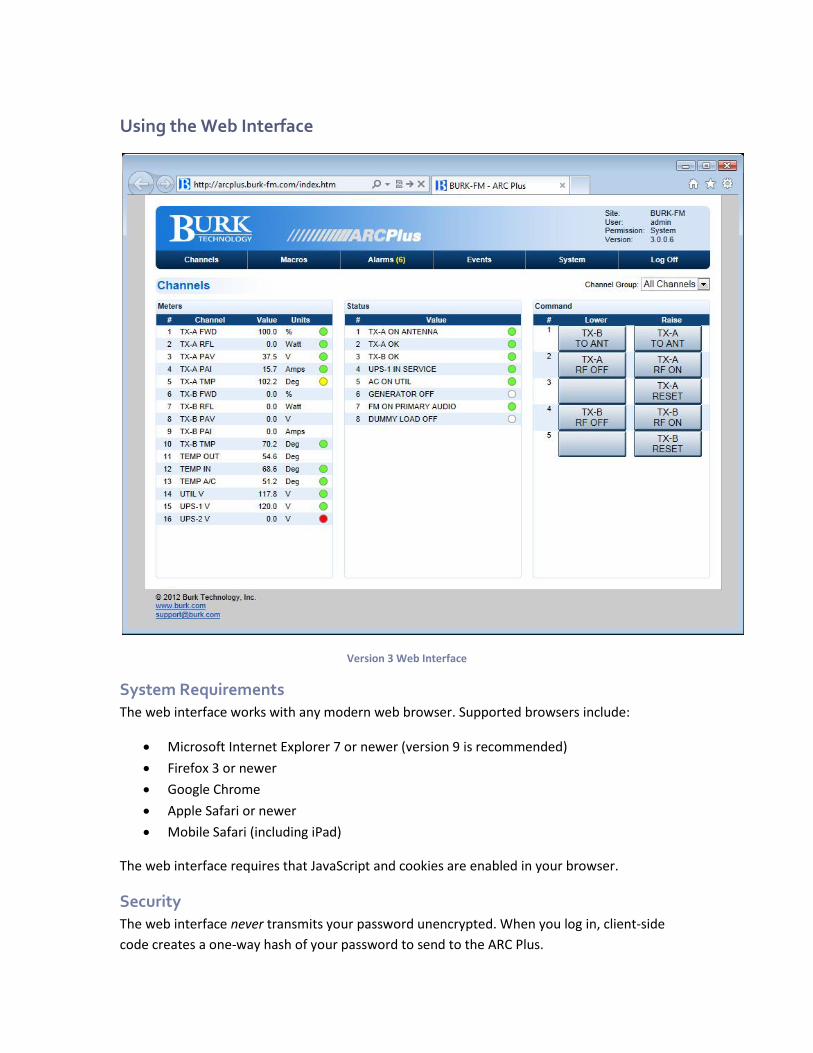
Using the Web Interface
Version 3 Web Interface
System Requirements
The web interface works with any modern web browser. Supported browsers include:
• Microsoft Internet Explorer 7 or newer (version 9 is recommended)
• Firefox 3 or newer
• Google Chrome
• Apple Safari or newer
• Mobile Safari (including iPad)
The web interface requires that JavaScript and cookies are enabled in your browser.
Security
The web interface never transmits your password unencrypted. When you log in, client-side
code creates a one-way hash of your password to send to the ARC Plus.
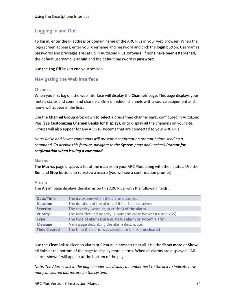
Using the Smartphone Interface
ARC Plus Version 3 Instruction Manual 84
Logging In and Out
To log in, enter the IP address or domain name of the ARC Plus in your web browser. When the
login screen appears, enter your username and password and click the login button. Usernames,
passwords and privileges are set up in AutoLoad Plus software. If none have been established,
the default username is admin and the default password is password.
Use the Log Off link to end your session.
Navigating the Web Interface
Channels
When you first log on, the web interface will display the Channels page. This page displays your
meter, status and command channels. Only unhidden channels with a source assignment and
name will appear in the lists.
Use the Channel Group drop down to select a predefined channel bank, configured in AutoLoad
Plus (see Customizing Channel Banks for Display), or to display all the channels on your site.
Groups will also appear for any ARC-16 systems that are connected to your ARC Plus.
Note: Raise and Lower commands will present a confirmation prompt before sending a
command. To disable this feature, navigate to the System page and uncheck Prompt for
confirmation when issuing a command.
Macros
The Macros page displays a list of the macros on your ARC Plus, along with their status. Use the
Run and Stop buttons to run/stop a macro (you will see a confirmation prompt).
Alarms
The Alarm page displays the alarms on this ARC Plus, with the following fields:
Date/Time The date/time when the alarm occurred Duration The duration of the alarm, if it has been resolved Severity The severity (warning or critical) of the alarm Priority The user-defined priority (a numeric value between 0 and 255) Type The type of alarm (such as status alarm or system alarm) Message A message describing the alarm description Time Cleared The time the alarm was cleared, or blank if uncleared
Use the Clear link to clear an alarm or Clear all alarms to clear all. Use the Show more or Show
all links at the bottom of the page to display more alarms. When all alarms are displayed, “All
alarms shown” will appear at the bottom of the page.
Note: The Alarms link in the page header will display a number next to the link to indicate how
many uncleared alarms are on the system.
Using the Smartphone Interface
ARC Plus Version 3 Instruction Manual 85
Events
The Events page displays the ARC Plus event list.
Use the Show more or Show all links at the bottom of the page to display more events. When all
events are displayed, “All events shown” will appear at the bottom of the page.
System
The System page allows you to perform several system related actions, described below:
Networking
Use the Networking page to set the networking parameters on the ARC Plus. Use the onscreen
help text for more information.
Rebooting
The Reboot link will reboot the ARC Plus. You will see a confirmation prompt before the system
reboots.
Resetting the system to Factory Defaults
The Reset to Factory Defaults link will reset the ARC Plus to its factory default settings. You will
see a confirmation prompt before this takes place.
Note: your network settings will not be reset.
Warning: Resetting the ARC Plus to factory defaults will erase all of your configuration and
data from the ARC Plus. It is strongly recommended that you back up your configuration in
AutoLoad Plus before doing so. This operation cannot be undone.
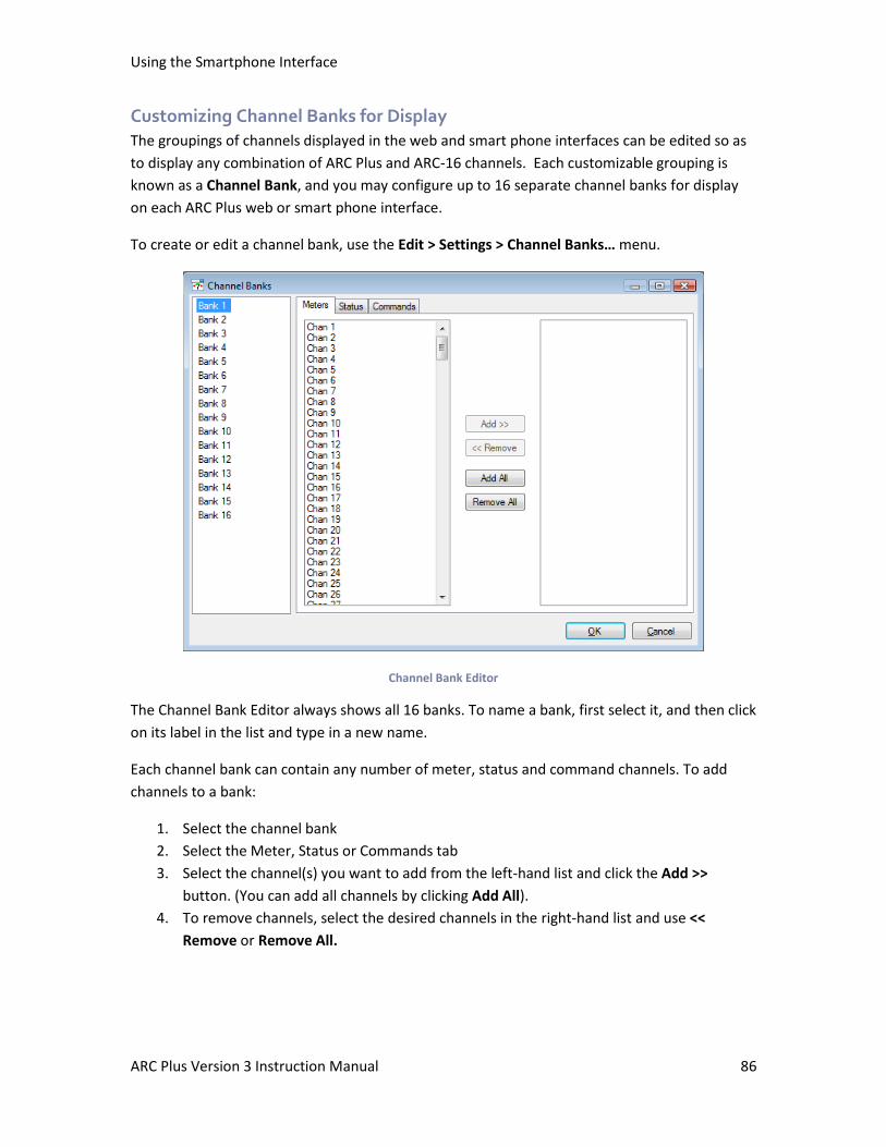
Using the Smartphone Interface
ARC Plus Version 3 Instruction Manual 86
Customizing Channel Banks for Display
The groupings of channels displayed in the web and smart phone interfaces can be edited so as
to display any combination of ARC Plus and ARC-16 channels. Each customizable grouping is
known as a Channel Bank, and you may configure up to 16 separate channel banks for display
on each ARC Plus web or smart phone interface.
To create or edit a channel bank, use the Edit > Settings > Channel Banks… menu.
Channel Bank Editor
The Channel Bank Editor always shows all 16 banks. To name a bank, first select it, and then click
on its label in the list and type in a new name.
Each channel bank can contain any number of meter, status and command channels. To add
channels to a bank:
1. Select the channel bank
2. Select the Meter, Status or Commands tab
3. Select the channel(s) you want to add from the left-hand list and click the Add >>
button. (You can add all channels by clicking Add All).
4. To remove channels, select the desired channels in the right-hand list and use <<
Remove or Remove All.
Using the Smartphone Interface
ARC Plus Version 3 Instruction Manual 87
The channel banks you configure in AutoLoad Plus will appear in the web interface and
smartphone interface.
Accessing the Original Web Interface
If you want to access the original, Java-based web interface, add /legacy/ to the URL for your
ARC Plus. For example, if your ARC Plus’ IP address is 192.168.0.100, navigate to:
http://192.168.0.100/legacy/
Note: be sure to include the trailing / character.
The legacy web interface is provided for compatibility purposes only and is not supported. Using
the new web interface is strongly recommended.
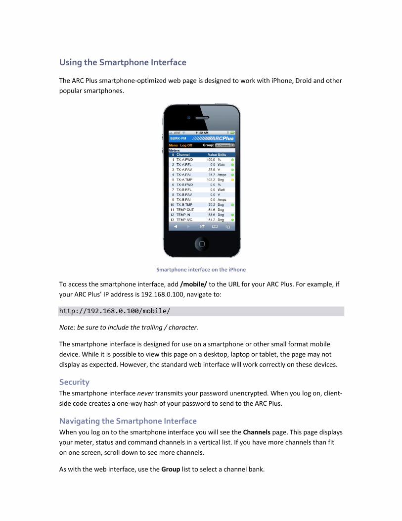
Using the Smartphone Interface
The ARC Plus smartphone-optimized web page is designed to work with iPhone, Droid and other
popular smartphones.
Smartphone interface on the iPhone
To access the smartphone interface, add /mobile/ to the URL for your ARC Plus. For example, if
your ARC Plus’ IP address is 192.168.0.100, navigate to:
http://192.168.0.100/mobile/
Note: be sure to include the trailing / character.
The smartphone interface is designed for use on a smartphone or other small format mobile
device. While it is possible to view this page on a desktop, laptop or tablet, the page may not
display as expected. However, the standard web interface will work correctly on these devices.
Security
The smartphone interface never transmits your password unencrypted. When you log on, client-
side code creates a one-way hash of your password to send to the ARC Plus.
Navigating the Smartphone Interface
When you log on to the smartphone interface you will see the Channels page. This page displays
your meter, status and command channels in a vertical list. If you have more channels than fit
on one screen, scroll down to see more channels.
As with the web interface, use the Group list to select a channel bank.
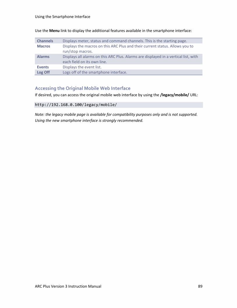
Using the Smartphone Interface
ARC Plus Version 3 Instruction Manual 89
Use the Menu link to display the additional features available in the smartphone interface:
Channels Displays meter, status and command channels. This is the starting page. Macros Displays the macros on this ARC Plus and their current status. Allows you to
run/stop macros. Alarms Displays all alarms on this ARC Plus. Alarms are displayed in a vertical list, with
each field on its own line. Events Displays the event list. Log Off Logs off of the smartphone interface.
Accessing the Original Mobile Web Interface
If desired, you can access the original mobile web interface by using the /legacy/mobile/ URL:
http://192.168.0.100/legacy/mobile/
Note: the legacy mobile page is available for compatibility purposes only and is not supported.
Using the new smartphone interface is strongly recommended.
Using the ESI Plus
The optional ESI Plus provides telephone dial-up control and dialout alarm notification. Installed
inside the ARC Plus main unit, the ESI Plus adds a line jack to the rear panel of the ARC Plus for
connection to a POTS line. This allows operators to dial the telephone number associated with
the phone line, enter a PIN, and then take readings and issue commands for any site linked to
the ESI. When configured to do so, the ESI will also dial out to alert operators to alarm
conditions.
Configuring the ESI Plus
Before you can use the ESI for monitoring, control and alarm notification, some configuration
steps are necessary:
• Assign ARC Plus sites to the ESI Plus
• Configure site, channel and unit labels for the ESI
• Configure greeting and goodbye messages
• Set up selective dialout lists
There are also default settings that you may adjust, such as number of rings before the ESI
answers an incoming call, the amount of time the ESI waits between phone numbers on the dial
out list, etc. All of these may be edited via AutoLoad Plus.
Calling the ESI
Calling in to the ESI allows you to monitor and control any remote site linked to the ESI. To place
a call to the ESI:
1. Dial the phone number for the line connected to ESI. After the specified number of rings, the ESI will pick up the line and speak the programmed greeting.
2. After the ESI picks up, a modem tone is played. Press any key to bypass the tone. Then enter your assigned PIN, followed by the # key. PINs are assigned in AutoLoad Plus under Speech Settings. If you make a mistake, press * to clear the entry and start over. If you enter an incorrect PIN, the ESI will speak, “Error,” and you can try again. Once you begin entering the PIN, you have 20 seconds to finish, or the ESI will disconnect.
Note: The durations allowed to begin entering the PIN and to complete entry are
configurable in the AutoLoad Plus software.
3. Once you enter your PIN, the ESI will speak the user-programmed welcome message, followed by the name of the site in which the ESI is installed and the number of alarms present at that site. After you log in, the ESI waits for a user command. All ESI functions are described later in this chapter, and the ESI command list can be found on ESI Plus Command List.

Using the ESI Plus
ARC Plus Version 3 Instruction Manual 91
Receiving Dialout Alarm Notifications
In order for the ESI to dial out and report alarm notifications, dialout must be enabled and the
site and channel must not be muted. Configure these parameters using the AutoLoad Plus
software or the front panel configuration menu.
1. The ESI executes the dialout process as follows: 2. A non-muted channel enters an alarm state, and any specified alarm delay duration
expires. 3. The ESI dials the first telephone number on the master dialout list and allows a specified
duration for the line to ring, a user to pick up, and a password to be entered. The amount of time allowed to log in can be modified using the AutoLoad Plus software.
4. If no user has supplied a password at the end of the time allowance, the ESI disconnects and remains idle for a user-specified amount of time so that the line is free for incoming calls. The pause duration can be modified using the AutoLoad Plus software.
5. After pausing, the ESI attempts the next phone number in the master dialout list. Once all of the phone numbers have been attempted, and if the alarm remains active, the ESI then attempts each number on the alarm channel’s selective dialout list, again pausing after each attempt.
6. If the alarm remains active after the selective dialout list is exhausted, the ESI restarts from the master dialout list and continues the process until the alarm is cleared.
7. Once a user answers a call and enters a password, the ESI announces the name of the site where the alarm is located, the number of alarms at that site, and the alarm conditions that prompted the dialout notifications.
8. The dialout process ends when a user logs in and clears the alarm. If a user disconnects without clearing the alarm, dialout will continue.
ESI Plus operation
Site Selection
In a multi-site system, the ESI can facilitate dial-in access and dialout alarm notification for an
unlimited number of ARC Plus sites. However, readings and commands are available for only
one site at a time. The site presently reporting conditions, and the site where commands will
take effect, is considered the selected site. When you begin an ESI session, a site is already
selected by default:
• When you dial in, the selected site is the site where the ESI is physically installed.
• When the ESI dials out, the selected site is the site where the alarm occurred.
In both cases, the ESI will speak the name of the selected site immediately after log-in.
To change the selected site using preset numbers:
1. Enter 401-498 to select a site preset (presets are configured in AutoLoad Plus). 2. The ESI will speak the name of the selected site and report the number of alarms at the
site.
Using the ESI Plus
ARC Plus Version 3 Instruction Manual 92
You may then enter any ESI command. If you do not know the preset number of a site, or if the
site is not stored as a preset:
1. Enter 499. The ESI will prompt you to use the telephone keypad to enter the first four letters of the site name. Use the site name assigned to the ARC Plus unit and displayed on the front panel, even if the site has a different name when spoken by the ESI.
2. If there is one site match, the ESI will announce the name of the selected site and report the number of alarms at the site. If there is more than one match, the ESI will prompt you to choose the site from a list of matches.
You may then enter any ESI command.
Note: You can always find out which site is currently selected by dialing 400.
Channel Selection and Meter Readings
Once the desired site is selected, you can choose a channel for readings and commands by
entering the channel number (1-256). The ESI speaks the name of the metering channel, the
current value, and the unit label.
To repeat a channel reading at any time, dial 000.
Shortcut: When entering channels 1-99, you can speed up the selection process by entering 001-
099.
Issuing Commands
After selecting the desired channel, you can issue a raise or lower command to that channel by
pressing # for raise or * for lower. The ESI will confirm your entry by saying, “raise,” or, “lower.”
You can then issue another raise or lower command, or enter any other ESI command. For an
updated metering reading at any time, enter 000.
Reviewing Status Conditions
To hear a report of all status channels at the site with a status high condition, enter 350. The ESI
will speak all Status On messages. If a channel’s status input is inverted, a low input results in a
status on message, which will be read in the status report.
The ESI will announce the end of the report when you have heard the last status message. You
can interrupt and exit a status report at any time with a new ESI command, including 000 to
repeat the selected channel’s meter reading. Entering 350 again will start a new status report.
Using the ESI Plus
ARC Plus Version 3 Instruction Manual 93
Reviewing Alarms
When the ESI dials out to report an alarm, it will speak the name of the alarm that prompted
dialout as soon as you log in. At any time, you can access a list of all alarms at the site by
entering 300. The ESI will report the number of alarms at the site, and then read the first alarm
in the list. The ESI waits for your input after each alarm. You have the following choices:
• Press # to clear the alarm and go on to the next one.
• Press * to leave the alarm active (not cleared) and go on to the next one.
• Press # # # to clear all alarms at the site. The ESI will prompt you to confirm before clearing all alarms.
You can temporarily suspend alarm notification on any active alarm by pressing * followed by
the desired number of hours (1-9). For example, press *4 to put alarm notification on hold for
four hours. After four hours, if the alarm is still active, the ESI will begin dialing out for this alarm
once again. This method allows operators to ignore an alarm for a period of time without
clearing it.
The ESI will tell you when it has reached the end of the alarm report. You can then enter any
command.
Running Macros
You can use the ESI to run or stop macros that are saved to the ARC Plus unit. To run or stop
macros:
1. Log in to the ESI. 2. Select the desired site by entering the site preset (401-498) or by spelling the site name
(499). 3. Once the desired site is selected, choose a macro by entering a macro preset number
601-698. Macro presets are set up using AutoLoad Plus software. If you wish to select a macro from a menu, dial 699.
4. The ESI announces the name of the macro you selected, and whether the macro is running or stopped.
5. To run the macro, press #. To stop the macro, press *. The ESI will confirm your selection and read the macro status after it runs or stops the macro.
6. When you are done with macros, dial 000 to exit and repeat the current metering channel reading.
Each time the ESI speaks the running or stopped status of the macro, the status is valid only at
the time the ESI executes its query. A macro that is running one moment may execute its last
line of code in the next moment, and the ESI will not automatically announce a change of status.
Entering a new run or stop command, reselecting the macro preset number (601-698) or
choosing the macro from the menu (699) will generate a new macro status update.
If a macro executes for a very brief duration, it is possible to issue a run command only to hear
the ESI announce the new status as “stopped.” This may happen when the macro completes its
last line of code before the ESI queries the new macro status.
Using the ESI Plus
ARC Plus Version 3 Instruction Manual 94
Besides running and stopping macros, you can listen to a list of currently running macros by
entering 600. The ESI will read the names of macros that are stored on the selected unit and
running at the moment you enter your query. Macros that stop during the macro report will be
reported as running.
Audio Input Monitoring
Next to the line jack on the ESI, there is an RCA audio jack, which allows the user to dial in to the
ESI and monitor the audio fed to that jack. To monitor the audio input:
1. Log in to the ESI. 2. Dial 994 to begin monitoring the audio input. You may issue channel commands while
the audio is playing. However, depending on the signal level, it is possible for the audio input to overpower DTMF tones.
3. Dial 995 to turn the audio input off. The audio input automatically turns off after 30 seconds.
Editing Master Phone Numbers
There are two types of ESI dialout lists: the master dialout list, and the selective alarm dialout
lists. Both are set up in the AutoLoad Plus software, and the master dialout list can be edited
during an ESI session by a user with
system-level privileges. The master dialout list allows users to receive notification of all alarms
prior to any other phone numbers being dialed.
Because the master phone number list can be edited via an ESI session, it provides a convenient
way for a user to add a temporary phone number to the dialout list. For example, if an operator
will be away from their phone or does not have access to their pager, they can call in to the ESI,
add their alternate phone number to the master dialout list, and the ESI will dial that phone
number any time an alarm is received (dialout must be enabled).
The master dialout list also makes it possible for users to skip setting up selective dialout lists if
all operators wish to be notified of all alarms in the system.
To edit the master dialout list during an ESI session:
1. Log in to the ESI with system-level privileges. 2. Enter 801-809 to select a master dialout entry 1 to 9. The ESI will respond by speaking
the phone number stored in that entry. 3. Press # to edit the phone number. The ESI will prompt you to enter the new phone
number. Use digits 0-9 only. If you make a mistake, press # and the ESI will revert to the previously saved phone number. Press * when you are done entering the new phone number. To delete an entry, press # followed by *.
4. The ESI will announce the new phone number entry. 5. Enter a new ESI command, or 999 to disconnect.
Using the ESI Plus
ARC Plus Version 3 Instruction Manual 95
Note: The master dialout list does not support the * or # characters, or pauses in the dialing
string. For these functions, set up one or more selective dialout lists using the AutoLoad Plus
software, and link the list to the desired alarm conditions.
Muting Alarms
In order for the ESI to dial out when an alarm occurs, the channel presenting the alarm must not
be muted. If the channel is muted, the ARC Plus will not record alarms at all, and the ESI will not
dialout when conditions are out of tolerance. Alarm monitoring may be enabled/disabled using
the front panel configuration menu, AutoLoad Plus software, or during an ESI session, as
described below. You can toggle alarm monitoring for all channels at a site, or for specific
metering and status channels.
To enable or disable alarm monitoring for all channels at a site:
1. Log in to the ESI with system-level privileges. 2. Dial 500. The ESI will report whether alarm monitoring is enabled or disabled for the
current site. 3. Press # to enable alarm monitoring, or * to disable it. The ESI will report the new alarm
monitoring condition. 4. You may then enter any ESI command.
To enable or disable alarm monitoring for a single status channel:
1. Log in to the ESI with system-level privileges. 2. Enter the channel number for the desired status channel. The ESI will read the meter
value and label for the channel. However, the status channel with the same channel number is still selected.
3. Dial 510. The ESI will report whether alarm monitoring is enabled or disabled for the status channel.
4. Press # to enable alarm monitoring, or * to disable it. The ESI will report the new alarm monitoring condition.
5. You may then enter any ESI command.
To enable or disable alarm monitoring for a single metering channel:
1. Log in to the ESI with system-level privileges. 2. Enter the channel number for the desired metering channel. The ESI will read the meter
value and label for the channel. 3. Dial 520. The ESI will report whether alarm monitoring is enabled or disabled for the
metering channel. 4. Press # to enable alarm monitoring, or * to disable it. The ESI will report the new alarm
monitoring condition. 5. You may then enter any ESI command.
Onboard Help
Built-in voice guidance on the ESI operates in either of two modes, terse or verbose. Verbose
mode is designed to help novice users navigate the various functions. The ESI confirms each
Using the ESI Plus
ARC Plus Version 3 Instruction Manual 96
command, speaks a context-sensitive help prompt after each command, and prompts the user
for a new command after a period of inactivity. Terse mode is for advanced users who need
minimal prompting. The ESI will confirm each command, and will only prompt for a new
command just prior to disconnecting.
The ESI operates in verbose mode by default. To switch to terse mode, dial 997. The ESI will
remain in terse mode for this and subsequent sessions, until a user dials 996 to switch back. In
addition to the context-sensitive prompts in verbose mode, any user can summon a complete
list of available commands by entering 998. The ESI will read a list of commands. You can
interrupt the list with a new command at any time. The ESI will finish reading the current phrase
before executing the new command.
Command Timeouts
When the ESI expects input from the user, it will wait for a user-specified amount of time before
disconnecting. The default duration is 60 seconds. If you need more time to enter a command,
enter 993. The amount of the time extension is configurable using the AutoLoad Plus software.
Disconnecting
When you are done using the ESI, enter 999. This makes the line immediately available for new
calls. If you hang up without disconnecting, it may take 60 seconds or more for the ESI to release
the phone line on its own, depending on the duration of the command timeout setting.
Using the ESI in Local Mode
It is possible to connect a telephone directly to the ARC Plus and use the ESI while it is not
connected to an outside phone line. This is useful for troubleshooting purposes.
To use the ESI in local mode:
1. Plug a telephone set into the RJ-11 connector of the ESI. 2. On the front panel of the unit, enter the configuration menu, select the ESI option, and
select “local.” Once the set is off-hook, accept the “local mode” selection. 3. The ESI will prompt you to log in, just as you would if you were dialing in remotely.
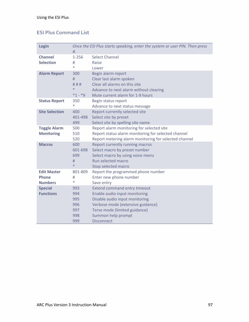
Using the ESI Plus
ARC Plus Version 3 Instruction Manual 97
ESI Plus Command List
Login Once the ESI Plus starts speaking, enter the system or user PIN. Then press #.
Channel Selection
1-256 Select Channel # Raise * Lower
Alarm Report 300 Begin alarm report # Clear last alarm spoken # # # Clear all alarms on this site * Advance to next alarm without clearing *1 - *9 Mute current alarm for 1-9 hours
Status Report 350 Begin status report * Advance to next status message
Site Selection 400 Report currently selected site 401-498 Select site by preset 499 Select site by spelling site name
Toggle Alarm Monitoring
500 Report alarm monitoring for selected site 510 Report status alarm monitoring for selected channel 520 Report metering alarm monitoring for selected channel
Macros 600 Report currently running macros 601-698 Select macro by preset number 699 Select macro by using voice menu # Run selected macro * Stop selected macro
Edit Master Phone Numbers
801-809 Report the programmed phone number # Enter new phone number * Save entry
Special Functions
993 Extend command entry timeout 994 Enable audio input monitoring 995 Disable audio input monitoring 996 Verbose mode (extensive guidance) 997 Terse mode (limited guidance) 998 Summon help prompt 999 Disconnect
Appendix A: Specifications
ARC Plus Version 3 Instruction Manual 98
Appendix A: Specifications
All Units
Operating Environment
0 to 40°C; 5 to 85% RH
Power Requirements
100 to 240VAC, 47-63 Hz, 1A
ARC Plus
Dimensions (WxHxD)
2RU: 19” x 3.5” x 12” (48.26 cm x 8.89 cm x 30.48cm)
Memory
Nonvolatile FLASH memory and battery-backed real-time clock store data for 20 years without
power.
Front Panel Interface
4x20-character Vacuum Fluorescent Display with jog wheel navigation
16 bi-color LEDs show status signals and are mappable to a variety of status data on any site or
channel
Dynamically updated command buttons show user-defined command text with tricolor
backlight
Alarm LED alerts users to local or global alarm conditions (user-definable)
Remote LED indicates maintenance mode status
Communication Ports
RJ-45 Ethernet port for 10/100BaseT network connection
4 PLUSBUS ports support connections for up to 16 IIUs and 32 ICRUs
COM ports for optional dial-up modem and ARC-16 connection
Appendix A: Specifications
ARC Plus Version 3 Instruction Manual 99
Integrated Input Unit
Dimensions (WxHxD)
1RU: 19” x 1.75” x 12” (48.26 cm x 4.45 cm x 30.48cm)
Metering Input Ranges & Accuracy
(-5 to 5), (0 to 5), (-10 to 10), (0 to 10VDC)
>99.75% accuracy, full-scale
Status Input Ranges
0 to 28VDC or switch closure
Integrated Command Relay Unit
Dimensions (WxHxD)
1RU: 19” x 1.75” x 12” (48.26 cm x 4.45 cm x 30.48cm)
Output Types
Form C relay output (C, NO, NC); each is user configurable for momentary or latching output.
Appendix B: FCC Part 68 Statement
This equipment complies with Part 68 of the FCC rules and the requirements adopted by the
ACTA. On the rear panel of this equipment is a label that contains, among other information, a
product identifier in the format US:AAAEQ##TXXXX. If requested, this number must be provided
to the telephone company. The jack USOC for this equipment is RJ11C. The Facility Interface
Code is 02LS2. The Service Order Code is 9.0Y.
A plug and jack used to connect this equipment to the premises wiring and telephone network
must comply with the applicable FCC Part 68 rules and requirements adopted by the ACTA. A
compliant telephone cord and modular plug is provided with this product. It is designed to be
connected to a compatible modular jack that is also compliant. See installation instructions for
details.
The Ringer Equivalency Number is used to determine the number of devices that may be
connected to a telephone line. Excessive RENs on a telephone line may result in the devices not
ringing in response to an incoming call. In most but not all areas, the sum of RENs should not
exceed five (5.0). To be certain of the number of devices that may be connected to a line, as
determined by the total RENs, contact the local telephone company. For products approved
after July 23, 2001, the REN for this product is part of the product identifier that has the format
US:AAAEQ##TXXXX. The digits represented by ## are the REN without a decimal point (e.g., 03 is
a REN of 0.3). For earlier products, the REN is separately shown on the label.
If the ARC Plus causes harm to the telephone network, the telephone company will notify you in
advance that temporary discontinuance of service may be required. But if advance notice isn't
practical, the telephone company will notify the customer as soon as possible. Also, you will be
advised of your right to file a complaint with the FCC if you believe it is necessary.
The telephone company may make changes in its facilities, equipment, operations or
procedures that could affect the operation of the equipment. If this happens the telephone
company will provide advance notice in order for you to make necessary modifications to
maintain uninterrupted service.
If trouble is experienced with the ARC Plus, for repair or warranty information, please contact
Burk Technology at 978-486-3711 or email [email protected]. There are no user-serviceable
parts. If the equipment is causing harm to the telephone network, the telephone company may
request that you disconnect the equipment until the problem is resolved.
Connection to party line service is subject to state tariffs. Contact the state public utility
commission, public service commission or corporation commission for information.

Appendix B: FCC Part 68 Statement
ARC Plus Version 3 Instruction Manual 101
If your facility has specially wired alarm equipment connected to the telephone line, ensure the
installation of the ARC Plus does not disable your alarm equipment. If you have questions about
what will disable alarm equipment, consult your telephone company or a qualified installer.
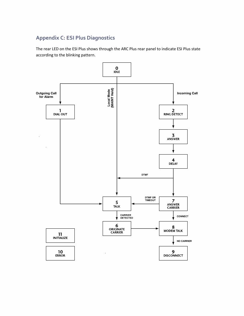
Appendix C: ESI Plus Diagnostics
The rear LED on the ESI Plus shows through the ARC Plus rear panel to indicate ESI Plus state
according to the blinking pattern.

Appendix D: ESI Plus Vocabulary
A
ABOVE
ACRODYNE
ADJUST
AEQ
AIR
AIR TOOLS
ALARM
ALARMS
ALL
ALTRONIC
AM
AMPS
ANALOG
ANTENNA
ARE
ARMSTRONG
ARRAKIS
ATLANTA
AUDEMAT-AZTEC
AUDIO
AUDIO TECHNICA
AUDIOLAB
AURAL
AUTO
AUTOMATIC
AUTOMATION
AUXILIARY
AVAILABLE
AXCERA
B
BACKUP
BAD
BALTIMORE
BASE
BASE CURRENT
BATTERY
BE
B E
BEACON
BEAM
BELAR
BELOW
BETABRITE
BEXT
BIRD
BOOT
BOSE
BOSTON
BROADCAST TOOLS
BUILDING
BURK
BURST
C
CARRIER
CELSIUS
CHANGE
CHANNEL
CHARLOTTE
CHICAGO
CHOOSE
CLEAR
CLEARED
CLEVELAND
CLOCK
COAX
COMBINER
COMMAND
COMPOSITE
COMPUTER
CONDITION
CONDITIONING
CONFIGURATION
CONTACT
CONTINENTAL
CONTROL
CONVERTER
CRASH
CRITICAL
CROWN
CURRENT
D
DALLAS
DANAGGAR
DAY
DAYPART
DAYTIME
DEAD
DECREASE
DEGREE
DEGREES
DEICER
DELAY
DELTA
DENON
DENVER
DETECTOR
DETROIT
DIAL
DIELECTRIC
DIGITAL
DIGITAL AUDIO LABS
DOLBY
DOOR
DOWN
DOWNLINK
DRIVE
DTV
DUMMY
E
EAS
EAST
EIGHT
EIGHTEEN
EIGHTY
ELECTRIC
ELEVEN
EMERGENCY
ENCO
ENERGY-ONIX

Appendix D: ESI Plus Vocabulary
ARC Plus Version 3 Instruction Manual 104
ENTER
EQUALS
EQUIPMENT
ERI
ERROR
EVENTIDE
EXCITER
EXIT
EXTERNAL
EXTREME
F
FADE
FAHRENHEIT
FAIL
FAN
FAULT
FIBER
FIFTEEN
FIFTY
FILAMENT
FINAL
FIRE
FIVE
FLASHER
FLOOR
FLOW
FM
FM SCA
FOR
FORTY
FORWARD
FOURTEEN
FREEZING
FREQUENCY
FRONT
FUEL
FURNACE
G
GAS
GE
GENERATOR
GEPCO
GOOD
GOODBYE
GORMAN REDLICH
GPS
GROUND
H
HARRIS
HARTFORD
HD
HEATER
HELLO
HELP
HERTZ
HI
HIGH
HOLLYANNE
HOT
HOURS
HOUSTON
HUNDRED
I
IBOC
IN
INCREASE
INDIANAPOLIS
INOVONICS
INPUT
INTERFACE
INTERLOCK
INTRAPLEX
INTRUSION
IP
IS
ISN’T
J
JVC
K
KILO
KILOVOLTS
KILOWATTS
KINTRONIC
L
LAN
LANLINK
LARCAN
LEFT
LEVEL
LIGHT
LIGHTWAVE
LIMIT
LINE
LINK
LINKS
LOAD
LOCAL
LOGITEK
LOOP
LOS ANGELES
LOW
LOWER
LUCID
LYNX
M
MACKIE
MACRO
MAGNET
MAIN
MANUAL
MARTI
MASTERCLOCK
MEGA
MEGAWATTS
METER
MIAMI
MICRO
MICROWAVE
MIDDLE
MILLI
MILLIAMPS
MILLIVOLTS
MINNEAPOLIS
MINOLTA
MINUS
MINUTES

Appendix D: ESI Plus Vocabulary
ARC Plus Version 3 Instruction Manual 105
MIRANDA
MODE
MODULATION
MODULE
MONITOR
MONO
MOSELEY
MOTOR
MOTOROLA
MULTIMEDIA
MUTE
MUTED
N
NASHVILLE
NAUTEL
NEC
NETWORK
NEUMANN
NEW YORK
NIGHT
NINE
NINETEEN
NINETY
NITROGEN
NO
NOISE
NORMAL
NORTH
NOT
NOW
NTSC
NUMBER
O
OFF
OFF AIR
OFFLINE
OMNIA
ON
AIR
ONE
ONLINE
ONLY
OPEN
ORBAN
ORLANDO
OUT
OUTDOOR
OUTPUT
OVER
OVERLOAD
P
PATTERN
PEAK
PELICAN
PERCENT
PHASE
PHILADELPHIA
PHOENIX
PHONE
PILOT
PITTSBURGH
PLATE
PLEASE
PORTLAND
POSTSUNSET
POTOMAC
POUND
POWER
PRESET
PRESSURE
PRESUNRISE
PRINTER
PROCESSOR
PROGRAM
PUMP
PUT
Q
QEI
R
RADIO
RAISE
RALEIGH
RATIO
RCA
READY
RECEIVER
RECORD
RECOVERY
REFLECTED
REJECT
RELATIVE
RELAY
REMOTE
REPEATER
RESET
RETURN
REVERSE
RF
RHODE AND SCHWARTZ
RIGHT
ROLAND
ROOM
RPU
RUN
RUNNING
S
SACRAMENTO
SAFE
SAN DIEGO
SAN FRANCISCO
SATELLITE
SBS
SCREEN
SEATTLE
SECURITY
SEE
SENSOR
SET
SEVEN
SEVENTEEN
SEVENTY
SHACK
SHUT
SHUTDOWN
SIDE
SIDELIGHTS

Appendix D: ESI Plus Vocabulary
ARC Plus Version 3 Instruction Manual 106
SIGHT
SIGNAL
SILENCE
SITE
SIX
SIXTEEN
SIXTY
SMOKE
SOUTH
SPEED
ST. LOUIS
STACK
STANDBY
STAR
STARLINK
START
STARTUP
STATION
STATUS
STEREO
STL
STOP
STOPPED
STROBE
STUDIO
SUB
SUBCARRIER
SUPPLY
SWITCH
SYNC
SYSTEM
T
T1
TAMPA
TAPE
TELEMETRY
TELOS
TEMP
TEMPERATURE
TEN
TERSE
TEST
TFT
THALES
THANK YOU
THERMAL
THIRTEEN
THIRTY
THIS
THOUSAND
THREE
TIME
TO
TOO
TOTAL
TOWER
TOWER LIGHTS
TRANSFER
TRANSLATOR
TRANSMITTER
TRIM
TRL
TSL
TV
TWELVE
TWENTY
TWO
TWO-WAY
U
UNDER
UNIT
UP
UPLINK
UPS
UTILITY
V
VERBOSE
VIDEO
VIRTUAL
VISUAL
VOICE
VOLTS
VSWR
W
WAIT
WAN
WARNING
WASHINGTON
WATER
WATTS
WEIGHT
WEST
WHY
X
Y
YOU
Z
ZERO
ZONE
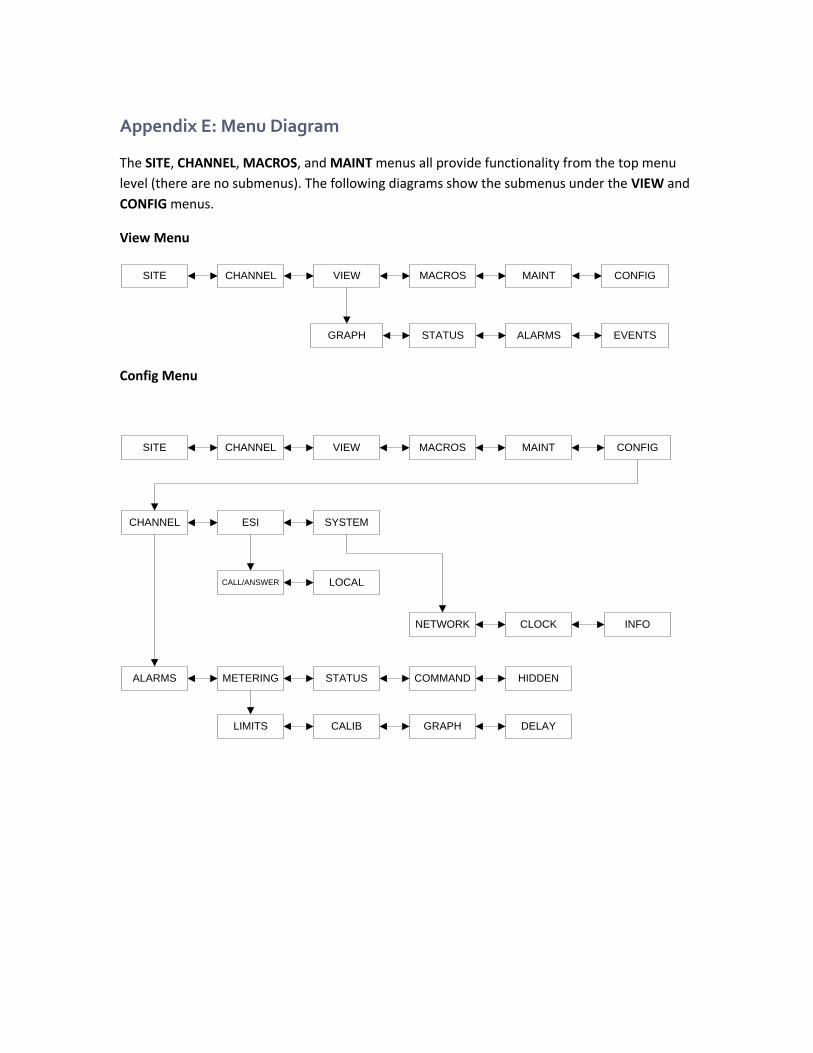
Appendix E: Menu Diagram
The SITE, CHANNEL, MACROS, and MAINT menus all provide functionality from the top menu
level (there are no submenus). The following diagrams show the submenus under the VIEW and
CONFIG menus.
View Menu
SITE CHANNEL VIEW MACROS MAINT CONFIG
GRAPH STATUS ALARMS EVENTS
Config Menu
ESICHANNEL SYSTEM
CLOCKNETWORK INFO
CALL/ANSWER LOCAL
ALARMS METERING STATUS COMMAND HIDDEN
LIMITS CALIB GRAPH DELAY
SITE CHANNEL VIEW MACROS MAINT CONFIG
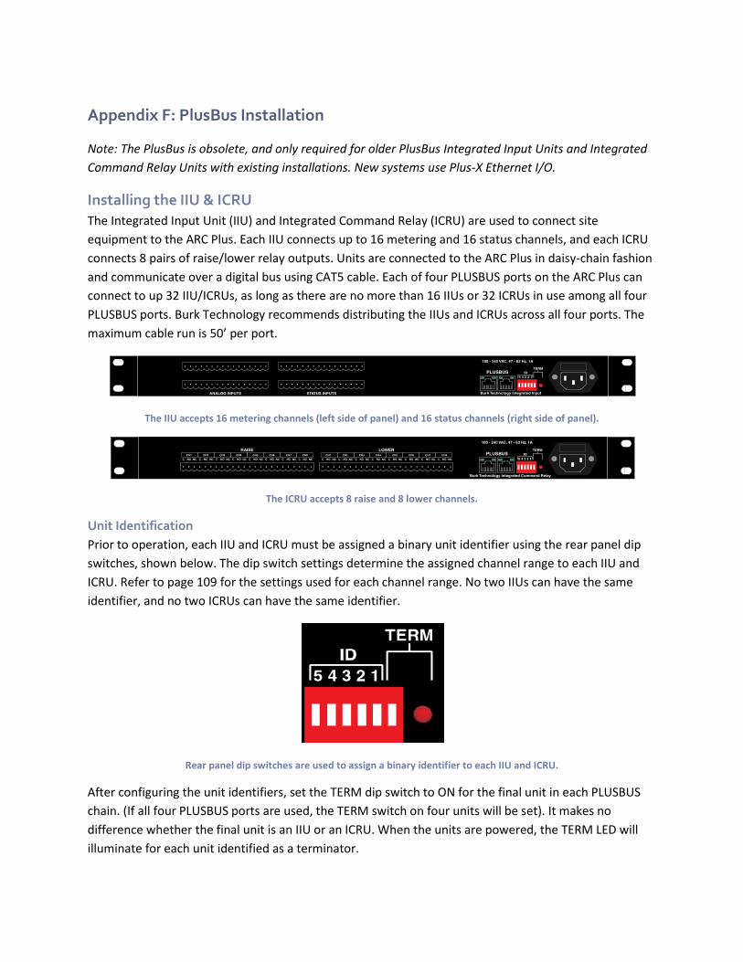
Appendix F: PlusBus Installation
Note: The PlusBus is obsolete, and only required for older PlusBus Integrated Input Units and Integrated
Command Relay Units with existing installations. New systems use Plus-X Ethernet I/O.
Installing the IIU & ICRU
The Integrated Input Unit (IIU) and Integrated Command Relay (ICRU) are used to connect site
equipment to the ARC Plus. Each IIU connects up to 16 metering and 16 status channels, and each ICRU
connects 8 pairs of raise/lower relay outputs. Units are connected to the ARC Plus in daisy-chain fashion
and communicate over a digital bus using CAT5 cable. Each of four PLUSBUS ports on the ARC Plus can
connect to up 32 IIU/ICRUs, as long as there are no more than 16 IIUs or 32 ICRUs in use among all four
PLUSBUS ports. Burk Technology recommends distributing the IIUs and ICRUs across all four ports. The
maximum cable run is 50’ per port.
The IIU accepts 16 metering channels (left side of panel) and 16 status channels (right side of panel).
The ICRU accepts 8 raise and 8 lower channels.
Unit Identification
Prior to operation, each IIU and ICRU must be assigned a binary unit identifier using the rear panel dip
switches, shown below. The dip switch settings determine the assigned channel range to each IIU and
ICRU. Refer to page 109 for the settings used for each channel range. No two IIUs can have the same
identifier, and no two ICRUs can have the same identifier.
Rear panel dip switches are used to assign a binary identifier to each IIU and ICRU.
After configuring the unit identifiers, set the TERM dip switch to ON for the final unit in each PLUSBUS
chain. (If all four PLUSBUS ports are used, the TERM switch on four units will be set). It makes no
difference whether the final unit is an IIU or an ICRU. When the units are powered, the TERM LED will
illuminate for each unit identified as a terminator.
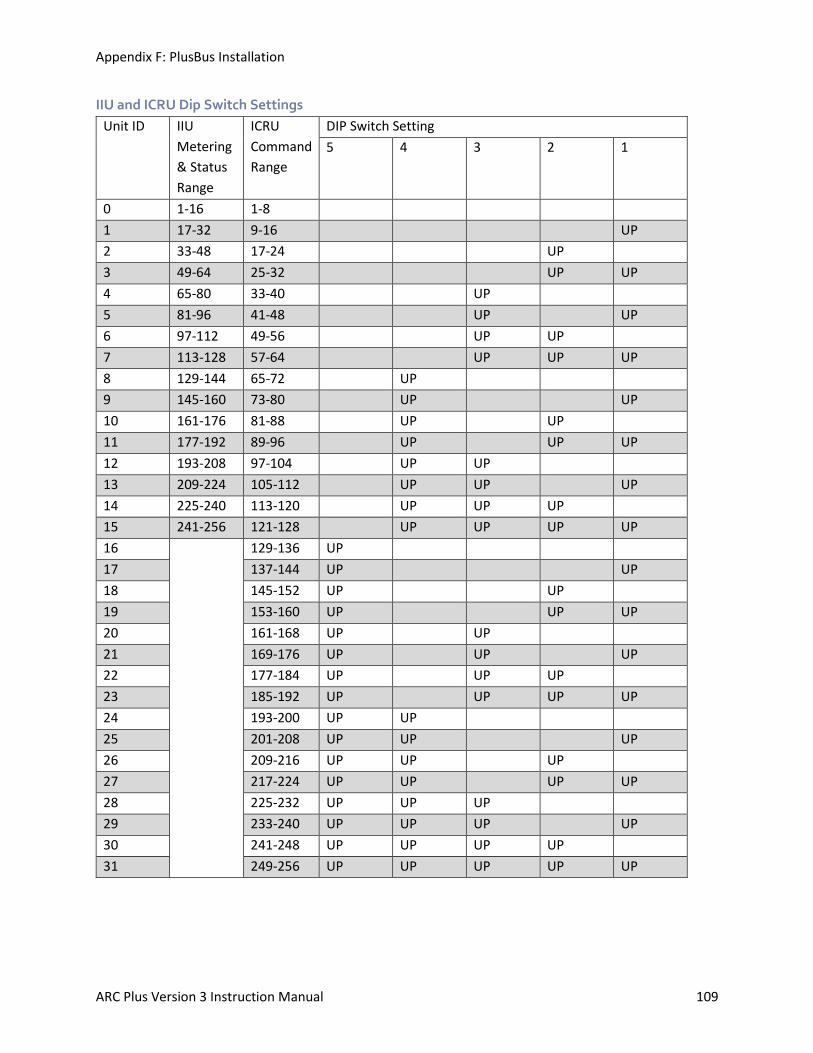
Appendix F: PlusBus Installation
ARC Plus Version 3 Instruction Manual 109
IIU and ICRU Dip Switch Settings
Unit ID IIU
Metering
& Status
Range
ICRU
Command
Range
DIP Switch Setting
5 4 3 2 1
0 1-16 1-8
1 17-32 9-16 UP
2 33-48 17-24 UP
3 49-64 25-32 UP UP
4 65-80 33-40 UP
5 81-96 41-48 UP UP
6 97-112 49-56 UP UP
7 113-128 57-64 UP UP UP
8 129-144 65-72 UP
9 145-160 73-80 UP UP
10 161-176 81-88 UP UP
11 177-192 89-96 UP UP UP
12 193-208 97-104 UP UP
13 209-224 105-112 UP UP UP
14 225-240 113-120 UP UP UP
15 241-256 121-128 UP UP UP UP
16 129-136 UP
17 137-144 UP UP
18 145-152 UP UP
19 153-160 UP UP UP
20 161-168 UP UP
21 169-176 UP UP UP
22 177-184 UP UP UP
23 185-192 UP UP UP UP
24 193-200 UP UP
25 201-208 UP UP UP
26 209-216 UP UP UP
27 217-224 UP UP UP UP
28 225-232 UP UP UP
29 233-240 UP UP UP UP
30 241-248 UP UP UP UP
31 249-256 UP UP UP UP UP
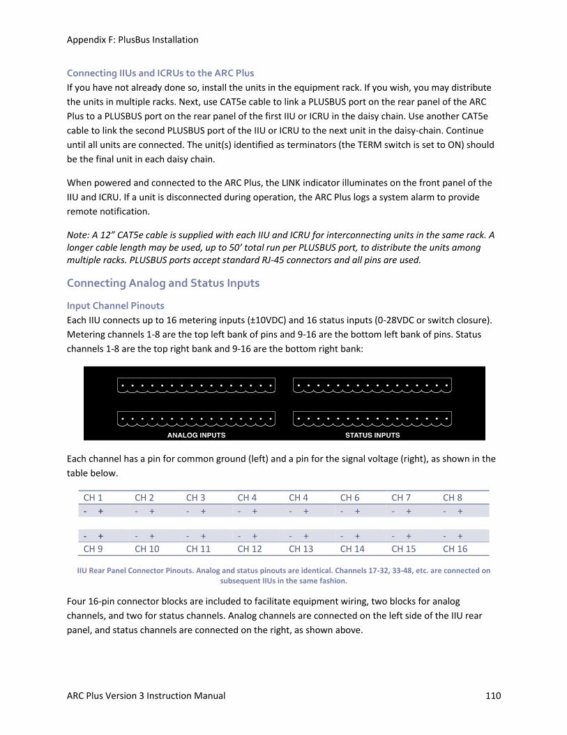
Appendix F: PlusBus Installation
ARC Plus Version 3 Instruction Manual 110
Connecting IIUs and ICRUs to the ARC Plus
If you have not already done so, install the units in the equipment rack. If you wish, you may distribute
the units in multiple racks. Next, use CAT5e cable to link a PLUSBUS port on the rear panel of the ARC
Plus to a PLUSBUS port on the rear panel of the first IIU or ICRU in the daisy chain. Use another CAT5e
cable to link the second PLUSBUS port of the IIU or ICRU to the next unit in the daisy-chain. Continue
until all units are connected. The unit(s) identified as terminators (the TERM switch is set to ON) should
be the final unit in each daisy chain.
When powered and connected to the ARC Plus, the LINK indicator illuminates on the front panel of the
IIU and ICRU. If a unit is disconnected during operation, the ARC Plus logs a system alarm to provide
remote notification.
Note: A 12” CAT5e cable is supplied with each IIU and ICRU for interconnecting units in the same rack. A longer cable length may be used, up to 50’ total run per PLUSBUS port, to distribute the units among multiple racks. PLUSBUS ports accept standard RJ-45 connectors and all pins are used.
Connecting Analog and Status Inputs
Input Channel Pinouts
Each IIU connects up to 16 metering inputs (±10VDC) and 16 status inputs (0-28VDC or switch closure).
Metering channels 1-8 are the top left bank of pins and 9-16 are the bottom left bank of pins. Status
channels 1-8 are the top right bank and 9-16 are the bottom right bank:
Each channel has a pin for common ground (left) and a pin for the signal voltage (right), as shown in the
table below.
CH 1 CH 2 CH 3 CH 4 CH 4 CH 6 CH 7 CH 8
- + - + - + - + - + - + - + - + - + - + - + - + - + - + - + - +
CH 9 CH 10 CH 11 CH 12 CH 13 CH 14 CH 15 CH 16
IIU Rear Panel Connector Pinouts. Analog and status pinouts are identical. Channels 17-32, 33-48, etc. are connected on subsequent IIUs in the same fashion.
Four 16-pin connector blocks are included to facilitate equipment wiring, two blocks for analog
channels, and two for status channels. Analog channels are connected on the left side of the IIU rear
panel, and status channels are connected on the right, as shown above.
Appendix F: PlusBus Installation
ARC Plus Version 3 Instruction Manual 111
Labeling Analog and Status Inputs
The accessory kit supplied with the IIU includes labels to identify the ground pin and supply voltage pin
for each channel. To align and affix the labels:
1. Start by designating one of the 16-pin connector blocks for metering channels 1-8. 2. Orient the connector block with the set screws facing toward you and below the wiring
terminals. 3. Peel off the label identifying ground and supply voltage for channels 1-8 and align the label on
top of the connector block with the ground symbol above the left-most input and the CH 1 designator above the second input from the left. When the label is aligned correctly, the designator for CH 8 will be positioned above the right-most wiring input and there will be a small amount of overhang on each side of the label.
4. Wrap the overhang around the side of the connector. 5. Next, label a new connector block for metering channels 9-16, followed by the two connector
blocks for status channels. On subsequent IIUs, apply labels for channels 17-32, 33-48, etc. in the same way.
Note: If you wish, you can apply the label directly on the rear panel of the IIU instead of on the connector
block.
Wiring the Input Channels
Once you have labeled the connector blocks for your input channels, attach wiring for each remote
control channel to the connector block using the connector labels as a guide. Secure the wiring using the
built-in set screws before attaching the connector block to the appropriate rear panel connector.
Metering Input Gain Adjustment
The IIU has 16 pairs of 3-pin headers (one pair for each metering channel, identified on the board by
channel number). These headers allow jumper-selectable gain adjustment for each metering channel. By
default, units ship with the jumpers configured for 1x gain (the IIU uses the voltage inputs as supplied by
the external equipment). This setting is appropriate for typical applications.
If the external equipment supplies a weak voltage sample, resetting the jumpers according to the silk-
screened diagram results in 4x gain (the IIU multiplies the voltage by 4 before scaling the value). Both
jumpers must be moved in unison.
Note: If both jumpers are missing, the associated metering channel will have 4x gain.
Toggling Between Switch Closure and Voltage-Controlled Status Inputs
The jumpers on headers JP1-JP16 on the IIU determine whether the respective status input is driven by
a switch closure or is voltage controlled. By default, units ship with the jumper engaged, enabling switch
closure (the status on condition occurs when the voltage sample is closed to ground). To configure one
or more channels to be voltage controlled, simply remove the jumper.
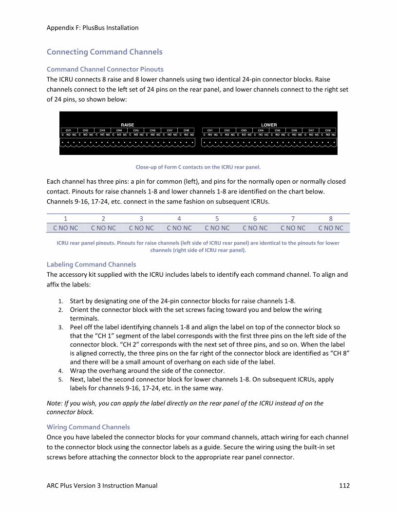
Appendix F: PlusBus Installation
ARC Plus Version 3 Instruction Manual 112
Connecting Command Channels
Command Channel Connector Pinouts
The ICRU connects 8 raise and 8 lower channels using two identical 24-pin connector blocks. Raise
channels connect to the left set of 24 pins on the rear panel, and lower channels connect to the right set
of 24 pins, so shown below:
Close-up of Form C contacts on the ICRU rear panel.
Each channel has three pins: a pin for common (left), and pins for the normally open or normally closed
contact. Pinouts for raise channels 1-8 and lower channels 1-8 are identified on the chart below.
Channels 9-16, 17-24, etc. connect in the same fashion on subsequent ICRUs.
1 2 3 4 5 6 7 8
C NO NC C NO NC C NO NC C NO NC C NO NC C NO NC C NO NC C NO NC
ICRU rear panel pinouts. Pinouts for raise channels (left side of ICRU rear panel) are identical to the pinouts for lower channels (right side of ICRU rear panel).
Labeling Command Channels
The accessory kit supplied with the ICRU includes labels to identify each command channel. To align and
affix the labels:
1. Start by designating one of the 24-pin connector blocks for raise channels 1-8. 2. Orient the connector block with the set screws facing toward you and below the wiring
terminals. 3. Peel off the label identifying channels 1-8 and align the label on top of the connector block so
that the “CH 1” segment of the label corresponds with the first three pins on the left side of the connector block. “CH 2” corresponds with the next set of three pins, and so on. When the label is aligned correctly, the three pins on the far right of the connector block are identified as “CH 8” and there will be a small amount of overhang on each side of the label.
4. Wrap the overhang around the side of the connector. 5. Next, label the second connector block for lower channels 1-8. On subsequent ICRUs, apply
labels for channels 9-16, 17-24, etc. in the same way.
Note: If you wish, you can apply the label directly on the rear panel of the ICRU instead of on the connector block.
Wiring Command Channels
Once you have labeled the connector blocks for your command channels, attach wiring for each channel
to the connector block using the connector labels as a guide. Secure the wiring using the built-in set
screws before attaching the connector block to the appropriate rear panel connector.