arbus 400 m arbus 400 u arbus 400 cf - jacto inc. · arbus 400 m arbus 400 u arbus 400 cf warning...
TRANSCRIPT
Operator’s Manual
English version - MI_USA-0219
EDITION - 07/2011CODE - 511147
ARBUS 400 MARBUS 400 U
ARBUS 400 CF
WARNINGRead Operator's Manual before setting up, operating, or maintainingsprayer. Failure to follow safety precautions in this manual an in labelson the product could result in serious injury or death to the operator orbystanders.Keep manual nearby for futher reference. If manual is demaged orillegible, contact your Jacto dealer or Jacto at the address below for areplacement.
JACTO INC.19217 SW 119th Ave
Tualatin, Oregon 97062Tel.: (503) 885-8723Fax: (800) 511-3671
Toll Free: (800) 522-8610E-mail: [email protected]
Home page: www.jacto.com

3
INTRODUCTION
JACTO RESERVES THE RIGHT TO CHANGE SPECIFICATIONS AND DESIGNWITHOUT PRIOR NOTICE.
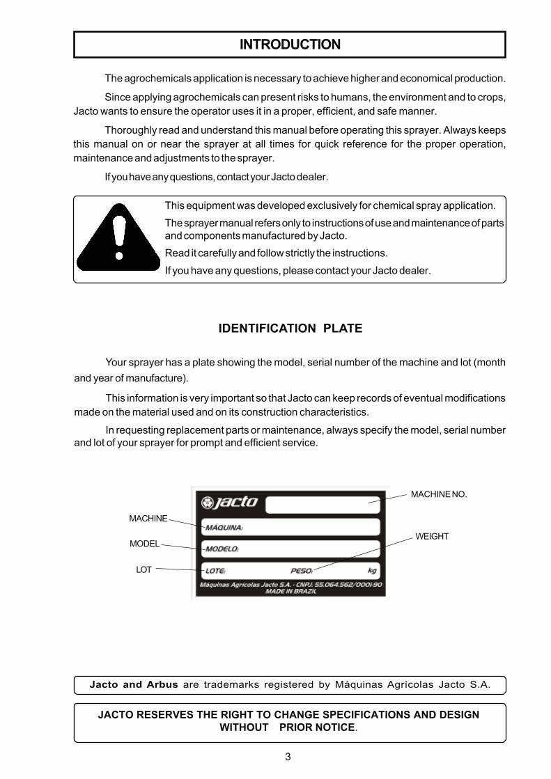
Your sprayer has a plate showing the model, serial number of the machine and lot (monthand year of manufacture).
This information is very important so that Jacto can keep records of eventual modificationsmade on the material used and on its construction characteristics.
In requesting replacement parts or maintenance, always specify the model, serial numberand lot of your sprayer for prompt and efficient service.
IDENTIFICATION PLATE
Jacto and Arbus are trademarks registered by Máquinas Agrícolas Jacto S.A.
The agrochemicals application is necessary to achieve higher and economical production.
Since applying agrochemicals can present risks to humans, the environment and to crops,Jacto wants to ensure the operator uses it in a proper, efficient, and safe manner.
Thoroughly read and understand this manual before operating this sprayer. Always keepsthis manual on or near the sprayer at all times for quick reference for the proper operation,maintenance and adjustments to the sprayer.
If you have any questions, contact your Jacto dealer.
This equipment was developed exclusively for chemical spray application.
The sprayer manual refers only to instructions of use and maintenance of partsand components manufactured by Jacto.
Read it carefully and follow strictly the instructions.
If you have any questions, please contact your Jacto dealer.
MACHINE
MODEL
LOT
MACHINE NO.
WEIGHT
4
TABLE OF CONTENTS
INTRODUCTION- Identification plate ........................................................................................................... 03
SAFETY- Operator's and owner's responsabilities .......................................................................... 05- Cautions when operating agricultural sprayer .................................................................. 06- Cautions on the maintenance and transportation ............................................................. 07- Handling chemicals ......................................................................................................... 08- Safety decals .................................................................................................................. 09
PRESENTATION OF SPRAYER- Arbus 400 M ...................................................................................................................... 11- Arbus 400 U ...................................................................................................................... 13- Arbus 400 CF.................................................................................................................... 15
MAIN COMPONENTS OF SPRAYER- Suction filter ....................................................................................................................... 17- Pump ............................................................................................................................ 17- Pressure regulator ............................................................................................................. 17- Nozzle ............................................................................................................................ 18- PTO Shaft .......................................................................................................................... 19- Spray lance (optional) ........................................................................................................ 19- Fan ............................................................................................................................ 20- Filler unit ............................................................................................................................ 21- Spray gun (optional) ........................................................................................................... 21- VDC cable control kit (optional) ......................................................................................... 22- Clean water tank ................................................................................................................ 23
OPERATIONAL PROCEDURES .......................................................................................... 24CHOOSING THE TRACTOR ................................................................................................. 25SETTING UP THE TRACTOR ............................................................................................... 26MOUNTING THE SPRAYER TO THE TRACTOR .................................................................. 27OPERATION AND ADJUSTMENTS- Spray aplication technology ............................................................................................... 29- Pressure regulator ............................................................................................................ 30- Flow rate ........................................................................................................................... 31- Calibrating the sprayer ...................................................................................................... 34- Diluting the agrochemicals................................................................................................. 35- Chemical container rinse .................................................................................................. 36- Washing chemical container .............................................................................................. 37
MAINTENANCE- Guidelines ......................................................................................................................... 38- Components ...................................................................................................................... 38- Lubrication table ................................................................................................................ 39- Components lubrication ..................................................................................................... 39- Belt tension ........................................................................................................................ 40- PTO Shaft .......................................................................................................................... 41- Winter storerage ................................................................................................................ 42- Trouble-shooting ................................................................................................................ 43
GENERAL CARE- Handling agricultural sprayers and chemicals ..................................................................... 46- After spraying .................................................................................................................... 46
STATEMENT OF LIMITED WARRANTY ............................................................................... 47
5
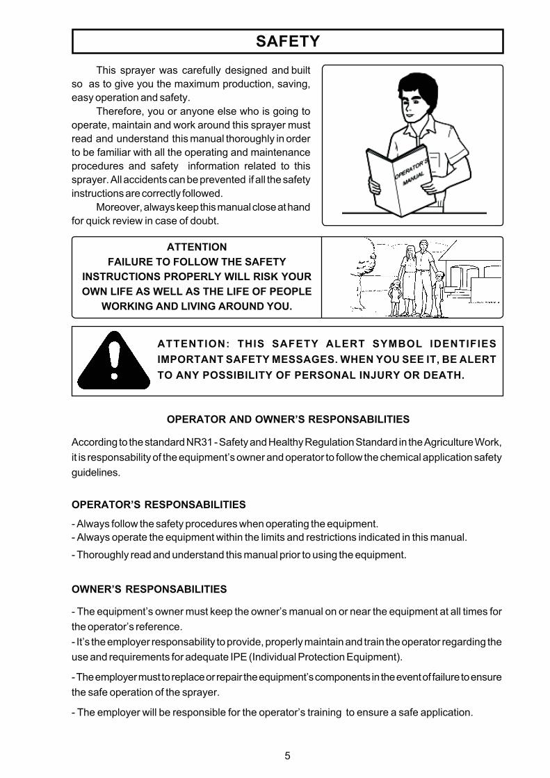
This sprayer was carefully designed and builtso as to give you the maximum production, saving,easy operation and safety.
Therefore, you or anyone else who is going tooperate, maintain and work around this sprayer mustread and understand this manual thoroughly in orderto be familiar with all the operating and maintenanceprocedures and safety information related to thissprayer. All accidents can be prevented if all the safetyinstructions are correctly followed.
Moreover, always keep this manual close at handfor quick review in case of doubt.
ATTENTIONFAILURE TO FOLLOW THE SAFETY
INSTRUCTIONS PROPERLY WILL RISK YOUROWN LIFE AS WELL AS THE LIFE OF PEOPLE
WORKING AND LIVING AROUND YOU.
SAFETY
OPERATOR AND OWNER’S RESPONSABILITIES
According to the standard NR31 - Safety and Healthy Regulation Standard in the Agriculture Work,it is responsability of the equipment’s owner and operator to follow the chemical application safetyguidelines.
OPERATOR’S RESPONSABILITIES
- Always follow the safety procedures when operating the equipment.- Always operate the equipment within the limits and restrictions indicated in this manual.
- Thoroughly read and understand this manual prior to using the equipment.
OWNER’S RESPONSABILITIES
- The equipment’s owner must keep the owner’s manual on or near the equipment at all times forthe operator’s reference.- It’s the employer responsability to provide, properly maintain and train the operator regarding theuse and requirements for adequate IPE (Individual Protection Equipment).
- The employer must to replace or repair the equipment’s components in the event of failure to ensurethe safe operation of the sprayer.
- The employer will be responsible for the operator’s training to ensure a safe application.
ATTENTION: THIS SAFETY ALERT SYMBOL IDENTIFIESIMPORTANT SAFETY MESSAGES. WHEN YOU SEE IT, BE ALERTTO ANY POSSIBILITY OF PERSONAL INJURY OR DEATH.
6
CAUTIONS WHEN OPERATING AGRICULTURAL SPRAYER
SAFETY
- Before operating this sprayer, read carefully and understand thoroughly this manual.
- Only qualified operators that have thoroughly read and understood the owner’s manualshould operate this sprayer.
- Do not ingest alcohol or drugs before or during the operation of this sprayer.
- Make sure that all the guards are in place before running the sprayer.
- Do not climb on or come down the sprayer when it is in motion.
- Turn the engine off before leaving the operator's place.
- This sprayer was designed and manufactured to support operations in the crops andon roads, tracks, trails or paths inside farms within the speed limit recommended by Jacto(limit of 18 mph in the routes inside the farm and 4 mph when spraying). The use of thesprayer above the limits mentioned is not approved by Jacto.
- This sprayer must be maneuvered in safe places, away from people, animals or any othersituation that offers risks of personal injuries or material damages. Make sure there are no peoplenear the sprayer before starting the engine.
- Do not make maneuvers or brake abruptly.
- The transportation of people and any loads whatsoever in the sprayer is strictly prohibited in anycircunstances.
ATTENTION: Do not touch PTO shafts, belts, fans or any other moving part while the sprayer is running.
Keep away from moving parts and be very careful with hands, feet, looseclothes, long hair, etc.
If you have any doubts/questions, please request Jacto TechnicalAssistance.
- Keep away children, aged people and animals while operating, servicing this sprayer and evenwhen the sprayer is stored.
- Do not run the pump dry.
- Do not exceed 540 rpm at the PTO.
- The PTO shaft ends must be securely locked to the PTO of the tractor and to the sprayer tongue.
- The PTO shaft guard must always remain in good repair and fastened by the safety chains. ThePTO shaft must work freely in its interior.
- Make sure the drawbar and the sprayer end are properly connected/fastened.
- Check and change the worn or broken parts.
- Only unhitch the sprayer on firm and level ground.
- Remove the controls installed on the tractor before disconnecting the sprayer.
- Fold the sprayer booms before unhitching it from the tractor.
7
SAFETY
- Activities of cleaning, lubrication, repair and adjustment should only be performed by qualifiedand trained professionals duly protected with the approved and proper PPE (Personal ProtectiveEquipment ) such as gloves, masks, goggles, safety boots, etc.
- Before performing any type of service, adjustment or maintenance in your sprayer,always disengage the PTO shaft and turn off the tractor engine.
- It is prohibited to make cleaning, lubrication and maintenance services with the sprayerin operation, except if its very operation is essential to make these services. In this case,all the special protection and signalization measures must be taken in order to preventaccidents.
- The removable guards can only be removed for maintenance. Then, they must beobligatorily placed back in their original position.
- Do not modify this sprayer in any way because this can impair its function and risk your safety.
- Keep your sprayer in thorough repair.
- For your and others' safety, remove the sprayer booms before transporting the sprayer on trailersor trucks.
- Failure to comply with these warnings may result in personal injuries or death.
- The employ in adverse and not recommended conditions can cause damage to thesprayer and components and will make void the warranty as well as exempt themanufacturer from any obligation to any accident or consequences.
- For the displacement and transport of the sprayer, the use of trucks or flatbeds arerecommended as long as measures for its perfect immobilization are taken in order toavoid accidents as result of improper accommodation.
- Require from the JACTO representative during the technical delivery of the sprayer that the properinstructions on assembly, maintenance, warranty be carefully explained.
CAUTIONS IN THE MAINTENANCE AND TRANSPORTATION
8
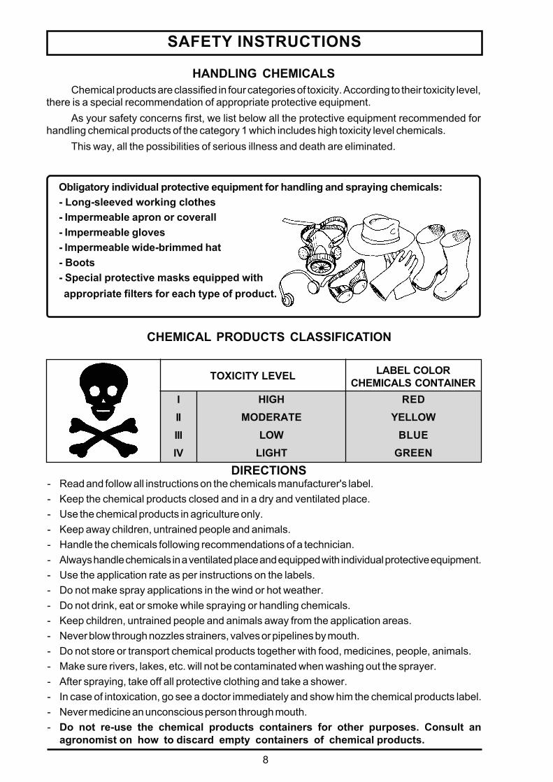
REDYELLOW
BLUEGREEN
SAFETY INSTRUCTIONS
Chemical products are classified in four categories of toxicity. According to their toxicity level,there is a special recommendation of appropriate protective equipment.
As your safety concerns first, we list below all the protective equipment recommended forhandling chemical products of the category 1 which includes high toxicity level chemicals.
This way, all the possibilities of serious illness and death are eliminated.
HANDLING CHEMICALS
CHEMICAL PRODUCTS CLASSIFICATION
Obligatory individual protective equipment for handling and spraying chemicals:- Long-sleeved working clothes- Impermeable apron or coverall- Impermeable gloves- Impermeable wide-brimmed hat- Boots- Special protective masks equipped with appropriate filters for each type of product.
LABEL COLORCHEMICALS CONTAINERTOXICITY LEVEL
IIIIIIIV
HIGHMODERATE
LOWLIGHT
DIRECTIONS- Read and follow all instructions on the chemicals manufacturer's label.- Keep the chemical products closed and in a dry and ventilated place.- Use the chemical products in agriculture only.- Keep away children, untrained people and animals.- Handle the chemicals following recommendations of a technician.- Always handle chemicals in a ventilated place and equipped with individual protective equipment.- Use the application rate as per instructions on the labels.- Do not make spray applications in the wind or hot weather.- Do not drink, eat or smoke while spraying or handling chemicals.- Keep children, untrained people and animals away from the application areas.- Never blow through nozzles strainers, valves or pipelines by mouth.- Do not store or transport chemical products together with food, medicines, people, animals.- Make sure rivers, lakes, etc. will not be contaminated when washing out the sprayer.- After spraying, take off all protective clothing and take a shower.- In case of intoxication, go see a doctor immediately and show him the chemical products label.- Never medicine an unconscious person through mouth.- Do not re-use the chemical products containers for other purposes. Consult an
agronomist on how to discard empty containers of chemical products.
9
SAFETY INSTRUCTIONS
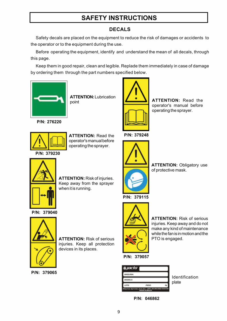
P/N: 379230
ATTENTION: Read theoperator's manual beforeoperating the sprayer.
ATTENTION: Read theoperator's manual beforeoperating the sprayer.
P/N: 379248
P/N: 276220
ATTENTION: Lubricationpoint
P/N: 379040
ATTENTION: Risk of injuries.Keep away from the sprayerwhen it is running.
P/N: 379057
ATTENTION: Risk of seriousinjuries. Keep away and do notmake any kind of maintenancewhile the fan is in motion and thePTO is engaged.
P/N: 379065
ATTENTION: Risk of seriousinjuries. Keep all protectiondevices in its places.
P/N: 046862
Identificationplate
DECALSSafety decals are placed on the equipment to reduce the risk of damages or accidents to
the operator or to the equipment during the use.
Before operating the equipment, identify and understand the mean of all decals, throughthis page.
Keep them in good repair, clean and legible. Replade them immediately in case of damageby ordering them through the part numbers specified below.
P/N: 379115
ATTENTION: Obligatory useof protective mask.

10
" Arbus 400"
P/N: 428912
SAFETY INSTRUCTIONS
P/N: 379123
ATTENTION: Obligatory useof hearing protector.
ATTENTION: Risk of seriousinjuries. Do not make anyoperation on the PTO shaft ifthe PTO is engaged.
P/N: 379008
P/N: 379131
ATTENTION: Obligatory useof protective clothing.
P/N: 379214
ATTENTION: Maximum speedallowed for the machine is 18.5mph.
P/N: 379222
ATTENTION: This machine isnot allowed in highways.
P/N: 515601
Instructions toconnect thePTO shaft
P/N: 428631
P/N: 169128
ATTENTION: Neveroperate the valve of thechemical rinse nozzle if thecontainer is not dulypositioned over the rinsenozzle.
Procedures for fanbelts tension.
P/N: 013169
Final test of the equipment.
11
PRESENTATION OF SPRAYER
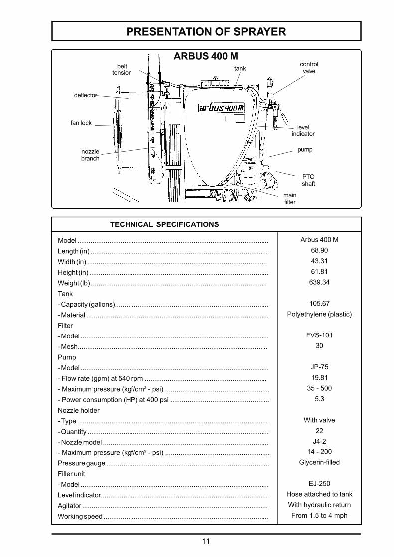
ARBUS 400 M
Model ......................................................................................................Length (in) ..............................................................................................Width (in) ...............................................................................................Height (in) ...............................................................................................Weight (lb) .............................................................................................Tank- Capacity (gallons).................................................................................- Material .................................................................................................Filter- Model ....................................................................................................- Mesh.....................................................................................................Pump- Model ....................................................................................................- Flow rate (gpm) at 540 rpm ................................................................- Maximum pressure (kgf/cm² - psi) .......................................................- Power consumption (HP) at 400 psi ....................................................Nozzle holder- Type .....................................................................................................- Quantity ................................................................................................- Nozzle model .......................................................................................- Maximum pressure (kgf/cm² - psi) .......................................................Pressure gauge ......................................................................................Filler unit- Model ....................................................................................................Level indicator.........................................................................................Agitator ...................................................................................................Working speed .......................................................................................
Arbus 400 M68.9043.3161.81639.34
105.67Polyethylene (plastic)
FVS-10130
JP-7519.81
35 - 5005.3
With valve22
J4-214 - 200
Glycerin-filled
EJ-250Hose attached to tankWith hydraulic returnFrom 1.5 to 4 mph
controlvalvetank
pump
levelindicator
mainfilter
belttension
nozzlebranch
PTOshaft
deflector
fan lock
TECHNICAL SPECIFICATIONS
12
PRESENTATION OF SPRAYER
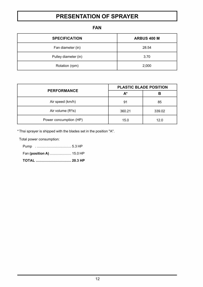
FAN
SPECIFICATION ARBUS 400 M
Fan diameter (in)
Pulley diameter (in)
Rotation (rpm)
28.54
3.70
2,000
Air speed (km/h)
Air volume (ft³/s)
Power concumption (HP)
85
339.02
12.0
PLASTIC BLADE POSITION
91
360.21
15.0
A* B
*Thsi sprayer is shipped with the blades set in the position "A".
Total power consumption:
Pump . ................................... 5.3 HP
Fan (position A) ...................... 15.0 HP
TOTAL .................................... 20.3 HP
PERFORMANCE
13
PRESENTATION OF SPRAYER
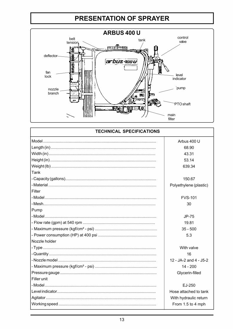
ARBUS 400 U
Model ......................................................................................................Length (in) ..............................................................................................Width (in) ...............................................................................................Height (in) ...............................................................................................Weight (lb) .............................................................................................Tank- Capacity (gallons).................................................................................- Material .................................................................................................Filter- Model ....................................................................................................- Mesh.....................................................................................................Pump- Model ....................................................................................................- Flow rate (gpm) at 540 rpm ................................................................- Maximum pressure (kgf/cm² - psi) .......................................................- Power consumption (HP) at 400 psi ....................................................Nozzle holder- Type .....................................................................................................- Quantity ................................................................................................- Nozzle model .......................................................................................- Maximum pressure (kgf/cm² - psi) .......................................................Pressure gauge ......................................................................................Filler unit- Model ....................................................................................................Level indicator.........................................................................................Agitator ...................................................................................................Working speed .......................................................................................
Arbus 400 U68.9043.3153.14639.34
150.67Polyethylene (plastic)
FVS-10130
JP-7519.81
35 - 5005.3
With valve16
12 - JA-2 and 4 - J5-214 - 200
Glycerin-filled
EJ-250Hose attached to tankWith hydraulic returnFrom 1.5 to 4 mph
controlvalvetank
´pump
levelindicator
mainfilter
belt tension
nozzlebranch
PTO shaft
deflector
fanlock
TECHNICAL SPECIFICATIONS

14
PRESENTATION OF SPRAYER
FAN
SPECIFICATION ARBUS 400 M
Fan diameter (in)
Pulley diameter (in)
Rotation (rpm)
28.54
4.13
1,800
Air speed (mph)
Air volume (ft³/s)
Power concumption (HP)
77
307.23
9.0
PLASTIC BLADE POSITION
83
328.42
11.0
A* B
*Thsi sprayer is shipped with the blades set in the position "A".
Total power consumption:
Pump . ................................... 5.3 HP
Fan (position A) ...................... 11.0 HP
TOTAL .................................... 16.3 HP
PERFORMANCE
15
PRESENTATION OF SPRAYER
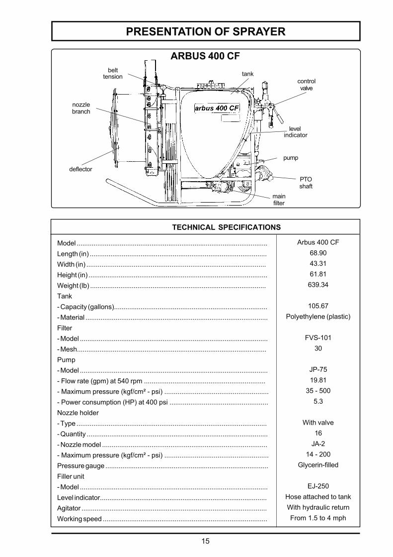
ARBUS 400 CF
controlvalve
level indicator
pump
PTOshaft
mainfilter
tankbelttension
deflector
nozzlebranch
Model ......................................................................................................Length (in) ..............................................................................................Width (in) ...............................................................................................Height (in) ...............................................................................................Weight (lb) .............................................................................................Tank- Capacity (gallons).................................................................................- Material .................................................................................................Filter- Model ....................................................................................................- Mesh.....................................................................................................Pump- Model ....................................................................................................- Flow rate (gpm) at 540 rpm ................................................................- Maximum pressure (kgf/cm² - psi) .......................................................- Power consumption (HP) at 400 psi ....................................................Nozzle holder- Type .....................................................................................................- Quantity ................................................................................................- Nozzle model .......................................................................................- Maximum pressure (kgf/cm² - psi) .......................................................Pressure gauge ......................................................................................Filler unit- Model ....................................................................................................Level indicator.........................................................................................Agitator ...................................................................................................Working speed .......................................................................................
Arbus 400 CF68.9043.3161.81639.34
105.67Polyethylene (plastic)
FVS-10130
JP-7519.81
35 - 5005.3
With valve16
JA-214 - 200
Glycerin-filled
EJ-250Hose attached to tankWith hydraulic returnFrom 1.5 to 4 mph
TECHNICAL SPECIFICATIONS
16
PRESENTATION OF SPRAYER
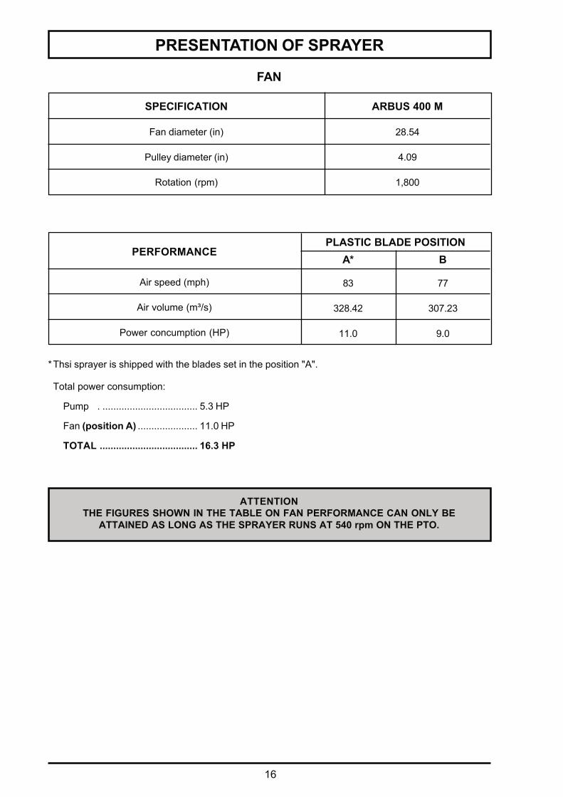
ATTENTIONTHE FIGURES SHOWN IN THE TABLE ON FAN PERFORMANCE CAN ONLY BE
ATTAINED AS LONG AS THE SPRAYER RUNS AT 540 rpm ON THE PTO.
FAN
SPECIFICATION ARBUS 400 M
Fan diameter (in)
Pulley diameter (in)
Rotation (rpm)
28.54
4.09
1,800
Air speed (mph)
Air volume (m³/s)
Power concumption (HP)
77
307.23
9.0
PLASTIC BLADE POSITION
83
328.42
11.0
A* B
*Thsi sprayer is shipped with the blades set in the position "A".
Total power consumption:
Pump . ................................... 5.3 HP
Fan (position A) ...................... 11.0 HP
TOTAL .................................... 16.3 HP
PERFORMANCE
17
JP - 402JP - 75
JP - 100JP - 150JP - 300
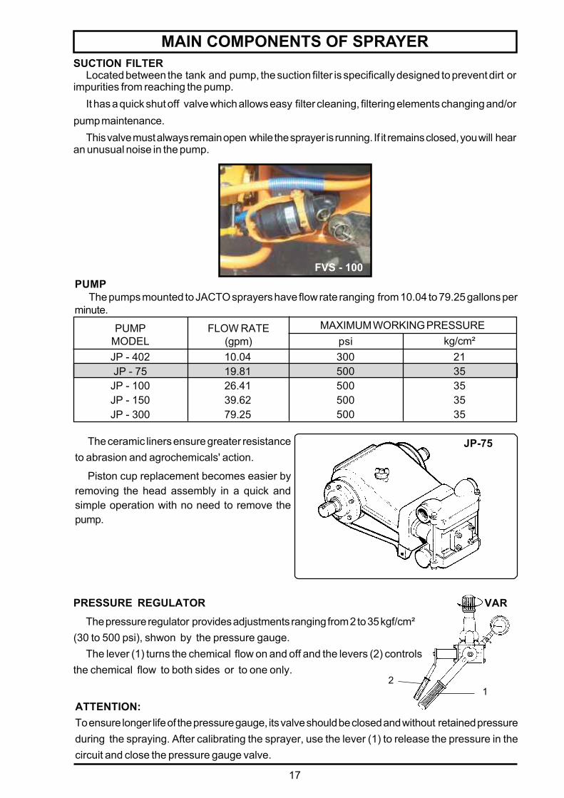
MAIN COMPONENTS OF SPRAYERSUCTION FILTER
Located between the tank and pump, the suction filter is specifically designed to prevent dirt orimpurities from reaching the pump.
It has a quick shut off valve which allows easy filter cleaning, filtering elements changing and/orpump maintenance.
This valve must always remain open while the sprayer is running. If it remains closed, you will hearan unusual noise in the pump.
PUMP The pumps mounted to JACTO sprayers have flow rate ranging from 10.04 to 79.25 gallons per
minute.
2135353535
10.0419.8126.4139.6279.25
300500500500500
PUMPMODEL
FLOW RATE(gpm) psi kg/cm²
MAXIMUM WORKING PRESSURE
The ceramic liners ensure greater resistanceto abrasion and agrochemicals' action.
Piston cup replacement becomes easier byremoving the head assembly in a quick andsimple operation with no need to remove thepump.
ATTENTION:To ensure longer life of the pressure gauge, its valve should be closed and without retained pressureduring the spraying. After calibrating the sprayer, use the lever (1) to release the pressure in thecircuit and close the pressure gauge valve.
JP-75
PRESSURE REGULATOR
The pressure regulator provides adjustments ranging from 2 to 35 kgf/cm²(30 to 500 psi), shwon by the pressure gauge.
The lever (1) turns the chemical flow on and off and the levers (2) controlsthe chemical flow to both sides or to one only.
VAR
12
FVS - 100
18
A
1
180º
90º
nozzle
swirl core
capring
DOUBLE NOZZLEHOLDER
MAIN COMPONENTS OF SPRAYER
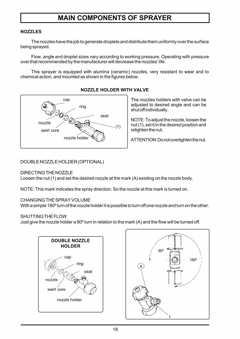
NOZZLES
The nozzles have the job to generate droplets and distribute them uniformly over the surfacebeing sprayed.
Flow, angle and droplet sizes vary according to working pressure. Operating with pressureover that recommended by the manufacturer will decrease the nozzles’ life.
This sprayer is equipped with alumina (ceramic) nozzles, very resistant to wear and tochemical action, and mounted as shown in the figures below.
DOUBLE NOZZLE HOLDER (OPTIONAL)
DIRECTING THE NOZZLELoosen the nut (1) and set the desired nozzle at the mark (A) existing on the nozzle body.
NOTE: This mark indicates the spray direction. So the nozzle at this mark is turned on.
CHANGING THE SPRAY VOLUMEWith a simple 180º turn of the nozzle holder it is possible to turn off one nozzle and turn on the other.
SHUTTING THE FLOWJust give the nozzle holder a 90º turn in relation to the mark (A) and the flow will be turned off.
nozzle holder
seat
The nozzles holders with valve can beadjusted to desired angle and can beshut off individually.
NOTE: To adjust the nozzle, loosen thenut (1), set it in the desired position andretighten the nut.
ATTENTION: Do not overtighten the nut.
NOZZLE HOLDER WITH VALVE
(1)
cap
ring
nozzle holder
swirl core
nozzle
seat
19
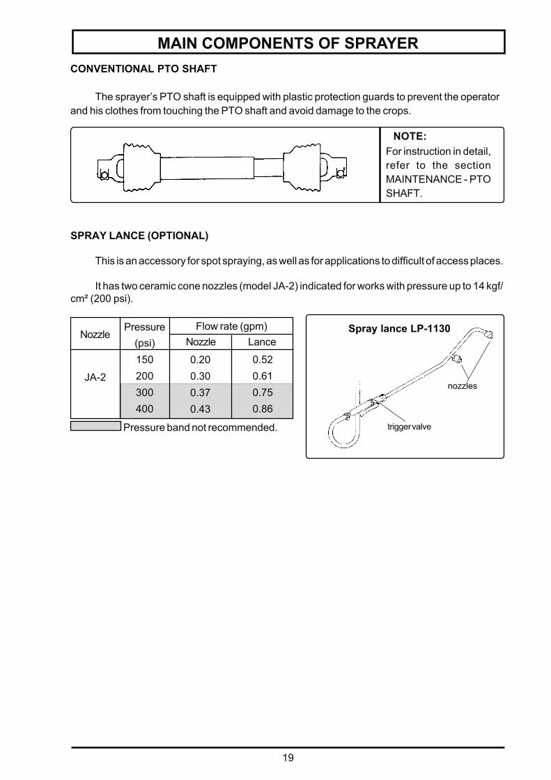
MAIN COMPONENTS OF SPRAYERCONVENTIONAL PTO SHAFT
The sprayer’s PTO shaft is equipped with plastic protection guards to prevent the operatorand his clothes from touching the PTO shaft and avoid damage to the crops.
NOTE:For instruction in detail,refer to the sectionMAINTENANCE - PTOSHAFT.
trigger valve
nozzles
Spray lance LP-1130
SPRAY LANCE (OPTIONAL)
This is an accessory for spot spraying, as well as for applications to difficult of access places.
It has two ceramic cone nozzles (model JA-2) indicated for works with pressure up to 14 kgf/cm² (200 psi).
0.520.610.750.86
JA-2
Pressure band not recommended.
Flow rate (gpm)Pressure(psi)
Nozzle
0.200.300.370.43
150200300400
Nozzle Lance
20
MAIN COMPONENTS OF SPRAYERFAN
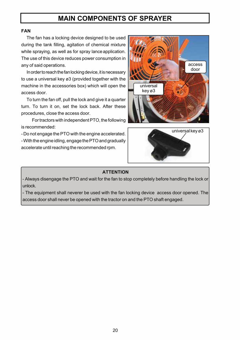
The fan has a locking device designed to be usedduring the tank filling, agitation of chemical mixturewhile spraying, as well as for spray lance application.The use of this device reduces power consumption inany of said operations.
In order to reach the fan locking device, it is necessaryto use a universal key ø3 (provided together with themachine in the accessories box) which will open theaccess door.
To turn the fan off, pull the lock and give it a quarterturn. To turn it on, set the lock back. After theseprocedures, close the access door.
For tractors with independent PTO, the followingis recommended:- Do not engage the PTO with the engine accelerated.- With the engine idling, engage the PTO and graduallyaccelerate until reaching the recommended rpm.
ATTENTION- Always disengage the PTO and wait for the fan to stop completely before handling the lock orunlock.- The equipment shall neverer be used with the fan locking device access door opened. Theaccess door shall never be opened with the tractor on and the PTO shaft engaged.
accessdoor
universalkey ø3
universal key ø3
21
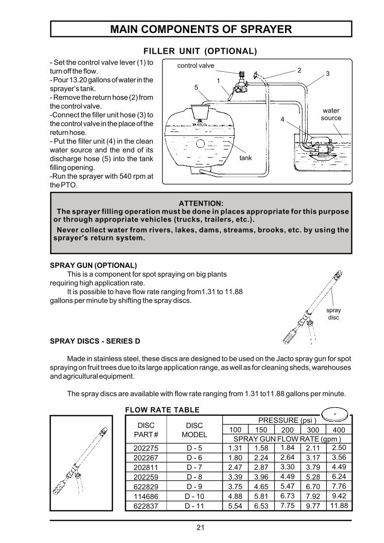
SPRAY GUN (OPTIONAL)This is a component for spot spraying on big plants
requiring high application rate.It is possible to have flow rate ranging from1.31 to 11.88
gallons per minute by shifting the spray discs.
MAIN COMPONENTS OF SPRAYER
- Set the control valve lever (1) toturn off the flow.- Pour 13.20 gallons of water in thesprayer’s tank.- Remove the return hose (2) fromthe control valve.-Connect the filler unit hose (3) tothe control valve in the place of thereturn hose.- Put the filler unit (4) in the cleanwater source and the end of itsdischarge hose (5) into the tankfilling opening.-Run the sprayer with 540 rpm atthe PTO.
5
5
31
control valve2
FILLER UNIT (OPTIONAL)
tank
4water
source
ATTENTION:The sprayer filling operation must be done in places appropriate for this purpose
or through appropriate vehicles (trucks, trailers, etc.).Never collect water from rivers, lakes, dams, streams, brooks, etc. by using the
sprayer's return system.
SPRAY DISCS - SERIES D
Made in stainless steel, these discs are designed to be used on the Jacto spray gun for spotspraying on fruit trees due to its large application range, as well as for cleaning sheds, warehousesand agricultural equipment.
The spray discs are available with flow rate ranging from 1.31 to11.88 gallons per minute.
spraydisc
DISCMODEL
D - 5D - 6D - 7D - 8D - 9D - 10D - 11
1.311.802.473.393.754.885.54
1.582.242.873.964.655.816.53
1.842.643.304.495.476.737.75
2.113.173.795.286.707.929.77
PRESSURE (psi )
SPRAY GUN FLOW RATE (gpm )100 150 200 300 400
2.503.564.496.247.769.42
11.88
DISCPART #
202275202267202811202259622829114686622837
FLOW RATE TABLE
22
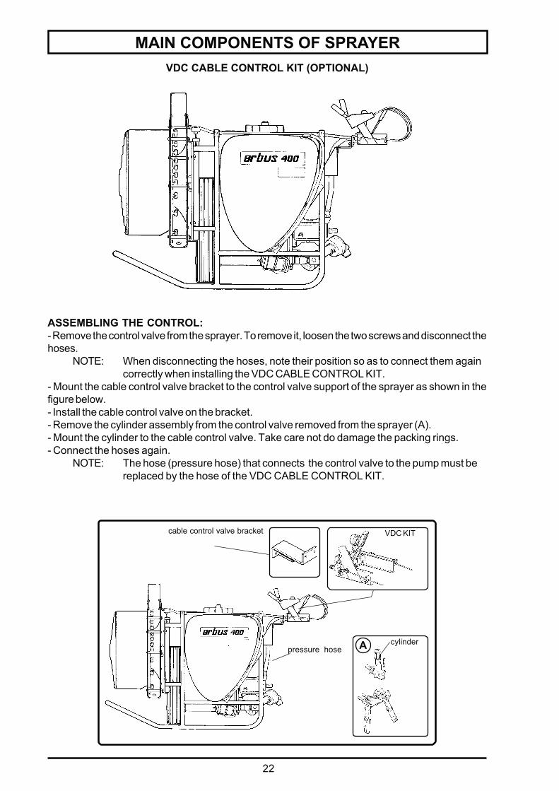
MAIN COMPONENTS OF SPRAYERVDC CABLE CONTROL KIT (OPTIONAL)
VDC KIT
cylinderA
cable control valve bracket
ASSEMBLING THE CONTROL:- Remove the control valve from the sprayer. To remove it, loosen the two screws and disconnect thehoses.
NOTE: When disconnecting the hoses, note their position so as to connect them againcorrectly when installing the VDC CABLE CONTROL KIT.
- Mount the cable control valve bracket to the control valve support of the sprayer as shown in thefigure below.- Install the cable control valve on the bracket.- Remove the cylinder assembly from the control valve removed from the sprayer (A).- Mount the cylinder to the cable control valve. Take care not do damage the packing rings.- Connect the hoses again.
NOTE: The hose (pressure hose) that connects the control valve to the pump must bereplaced by the hose of the VDC CABLE CONTROL KIT.
pressure hose
23
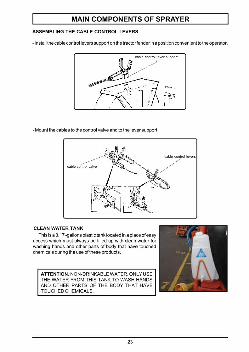
MAIN COMPONENTS OF SPRAYERASSEMBLING THE CABLE CONTROL LEVERS
- Install the cable control levers support on the tractor fender in a position convenient to the operator.
cable control lever support
- Mount the cables to the control valve and to the lever support.
cable control valve
cable control levers
CLEAN WATER TANK
ATTENTION: NON-DRINKABLE WATER. ONLY USETHE WATER FROM THIS TANK TO WASH HANDSAND OTHER PARTS OF THE BODY THAT HAVETOUCHED CHEMICALS.
This is a 3.17 -gallons plastic tank located in a place of easyaccess which must always be filled up with clean water forwashing hands and other parts of body that have touchedchemicals during the use of these products.
24
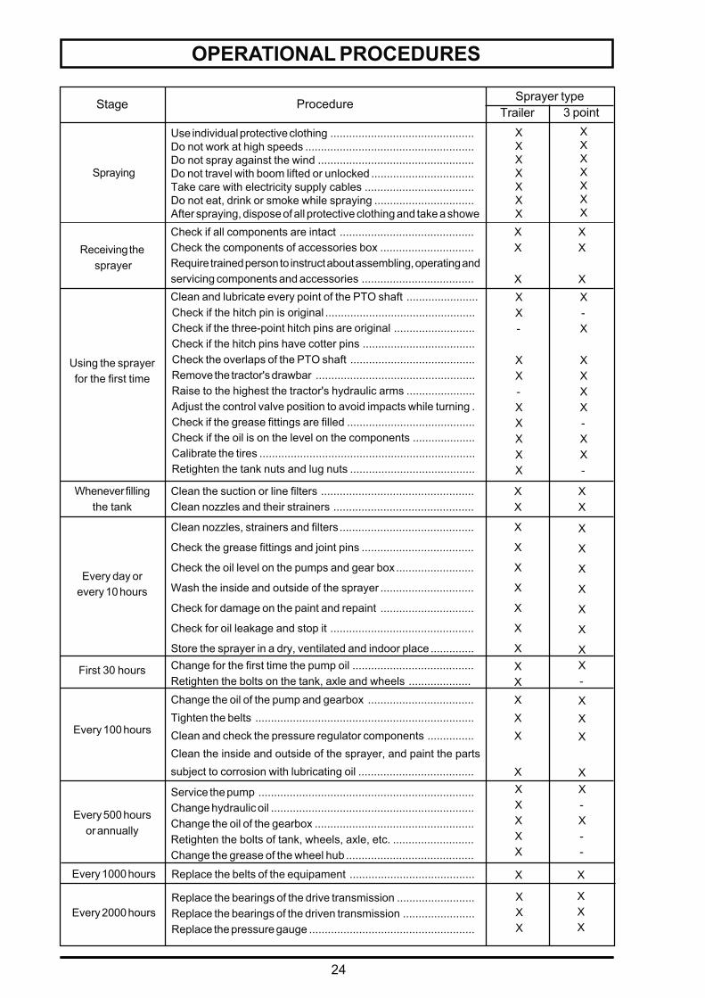
OPERATIONAL PROCEDURES
Change the oil of the pump and gearbox ..................................Tighten the belts ......................................................................Clean and check the pressure regulator components ...............Clean the inside and outside of the sprayer, and paint the partssubject to corrosion with lubricating oil .....................................
XXX
X
Sprayer typeStage ProcedureTrailer 3 point
Check if all components are intact ...........................................Check the components of accessories box ..............................Require trained person to instruct about assembling, operating andservicing components and accessories ....................................
Clean and lubricate every point of the PTO shaft .......................Check if the hitch pin is original ................................................Check if the three-point hitch pins are original ..........................Check if the hitch pins have cotter pins ....................................Check the overlaps of the PTO shaft ........................................Remove the tractor's drawbar ...................................................Raise to the highest the tractor's hydraulic arms ......................Adjust the control valve position to avoid impacts while turning .Check if the grease fittings are filled .........................................Check if the oil is on the level on the components ....................Calibrate the tires .....................................................................Retighten the tank nuts and lug nuts ........................................
Whenever fillingthe tank
Clean the suction or line filters .................................................Clean nozzles and their strainers .............................................
Change for the first time the pump oil .......................................Retighten the bolts on the tank, axle and wheels ....................
Receiving the sprayer
Using the sprayerfor the first time
Every day orevery 10 hours
First 30 hours
Every 100 hours
XX
X
XX
XXX-
XX-XXXXX
X-X
XXXX-XX-
XX
XX
X
X
X
X
X
X
X
X
X
X
X
X
X
XXX
X-
XXX
X
Spraying
Use individual protective clothing ..............................................Do not work at high speeds ......................................................Do not spray against the wind ..................................................Do not travel with boom lifted or unlocked .................................Take care with electricity supply cables ...................................Do not eat, drink or smoke while spraying ................................After spraying, dispose of all protective clothing and take a showe
XXXXXXX
XXXXXXX
Clean nozzles, strainers and filters...........................................
Check the grease fittings and joint pins ....................................
Check the oil level on the pumps and gear box.........................
Wash the inside and outside of the sprayer ..............................
Check for damage on the paint and repaint ..............................
Check for oil leakage and stop it ..............................................
Store the sprayer in a dry, ventilated and indoor place ..............
Service the pump .....................................................................Change hydraulic oil .................................................................Change the oil of the gearbox ...................................................Retighten the bolts of tank, wheels, axle, etc. ..........................Change the grease of the wheel hub .........................................
Every 500 hoursor annually
XXXXX
X-X--
Every 1000 hours X X
Every 2000 hoursReplace the bearings of the drive transmission .........................Replace the bearings of the driven transmission .......................Replace the pressure gauge .....................................................
XXX
XXX
Replace the belts of the equipament ........................................
25
ATTENTIONIn this case the recommended tractor should have minimal nominal
power of 38.5 HP and weigh at least gross 1,521.19 lb.
PROCEDURESDifferent working conditions lead us to adopt the following criterion for choosing the tractor that
will drive the Arbus 400 line sprayers.
- Check the sprayer weight on the identification plate.- Check the tank capacity.- Check in the specifications table the total power consumption of the sprayer at the PTO.
Example:Sprayer weight = 639.34 lbTank capacity = 105.67 gallonsTotal power consumption =20.3 HP
CHOOSING THE TRACTOR CONSIDERINGTHE POWER CONSUMPTION AND THE LOAD TO BE TRANSPORTED
1st - POWER CONSUMPTIONThe tractor should have power (HP) at least 90% higher than the power required to run the sprayer.Ex.:Power required by the sprayer = 20.3 HP
Minimum tractor nominal power = 38.5 HP
2nd - LOAD TO BE TRANSPORTEDThe tractor gross weight should be at least equal to the sprayer gross weight (sprayer net weight
plus full tank weight).Ex: Sprayer net weight = 639.34 lb
Filled up tank = approximately 881.85 lb (105.67 gallons tank)Tractor gross weight =1,521.19 lb or more
CHOOSING THE TRACTOR
26
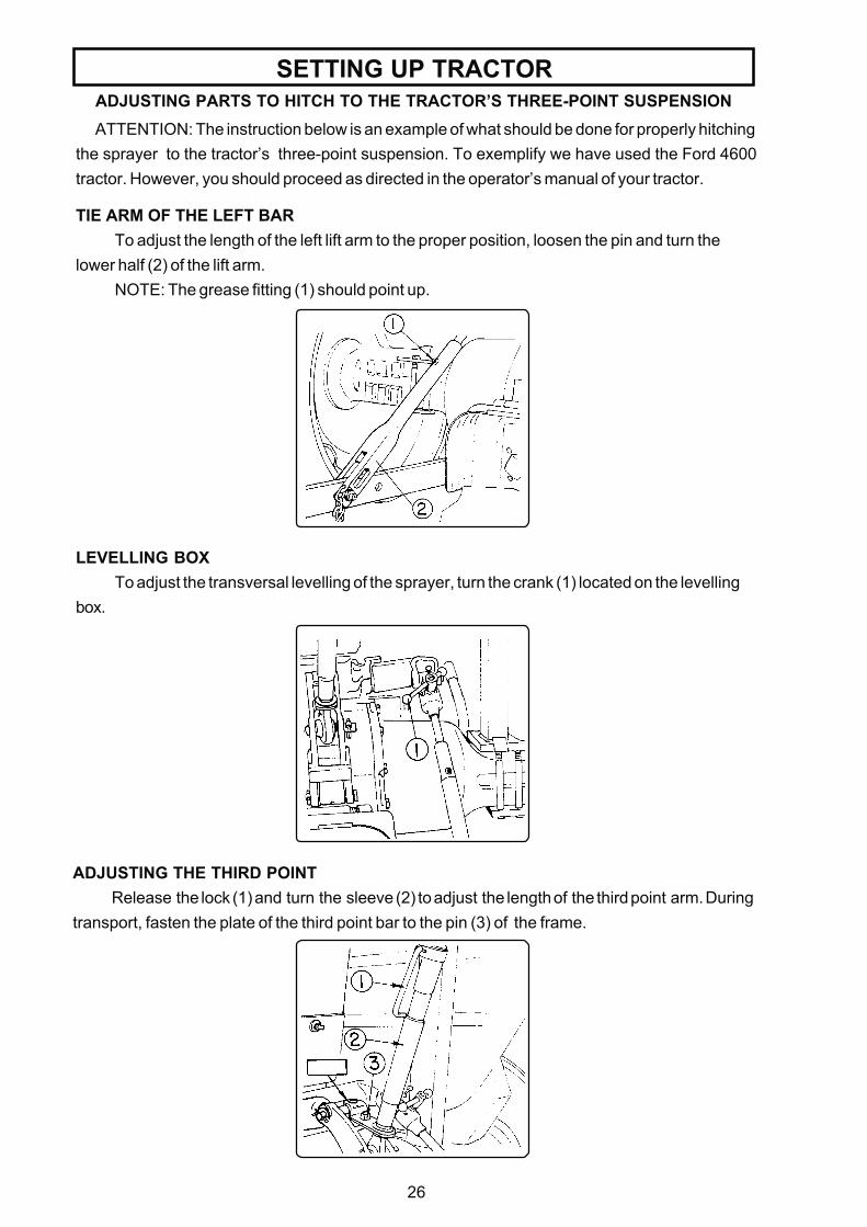
SETTING UP TRACTORADJUSTING PARTS TO HITCH TO THE TRACTOR’S THREE-POINT SUSPENSIONATTENTION: The instruction below is an example of what should be done for properly hitching
the sprayer to the tractor’s three-point suspension. To exemplify we have used the Ford 4600tractor. However, you should proceed as directed in the operator’s manual of your tractor.
LEVELLING BOXTo adjust the transversal levelling of the sprayer, turn the crank (1) located on the levelling
box.
ADJUSTING THE THIRD POINTRelease the lock (1) and turn the sleeve (2) to adjust the length of the third point arm. During
transport, fasten the plate of the third point bar to the pin (3) of the frame.
TIE ARM OF THE LEFT BARTo adjust the length of the left lift arm to the proper position, loosen the pin and turn the
lower half (2) of the lift arm.NOTE: The grease fitting (1) should point up.
27
SETTING UP TRACTOR
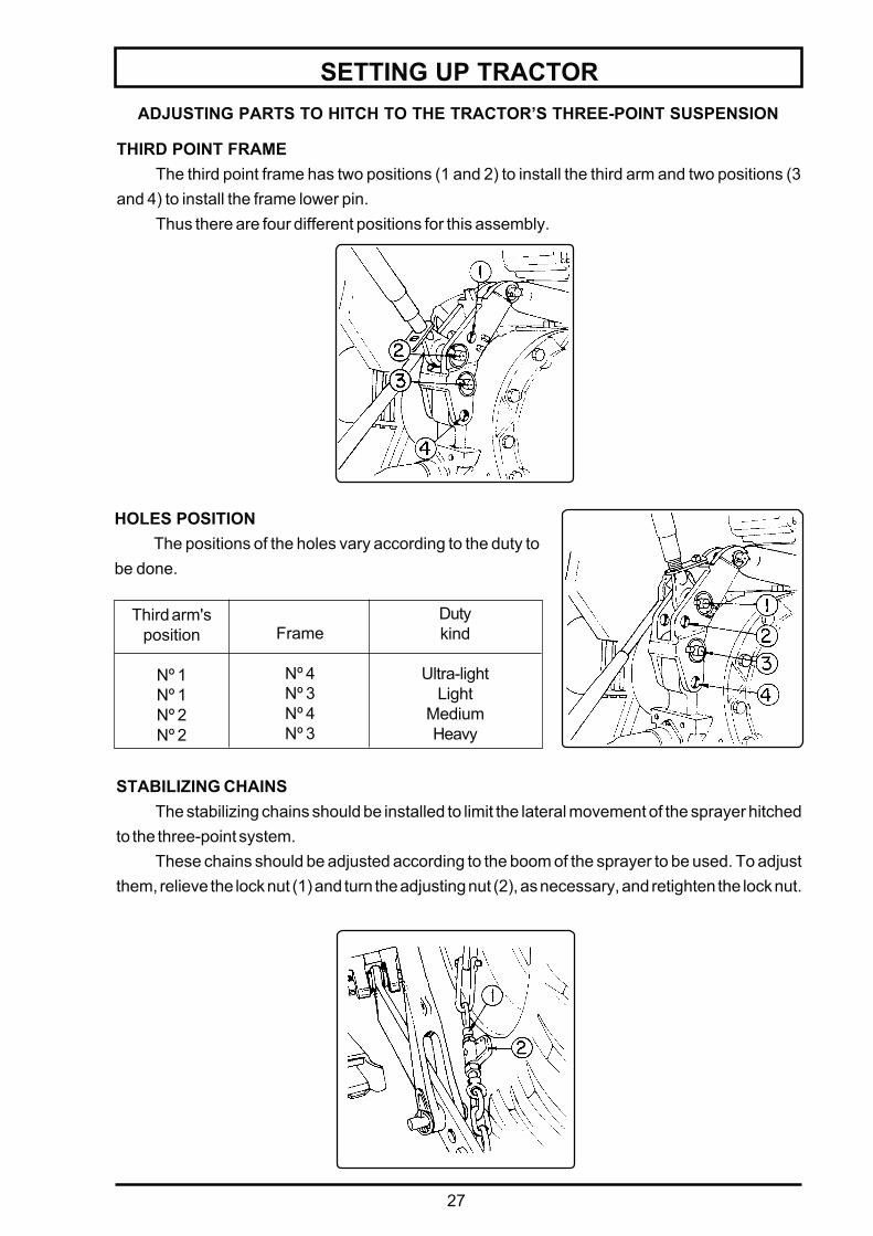
THIRD POINT FRAMEThe third point frame has two positions (1 and 2) to install the third arm and two positions (3
and 4) to install the frame lower pin.Thus there are four different positions for this assembly.
ADJUSTING PARTS TO HITCH TO THE TRACTOR’S THREE-POINT SUSPENSION
HOLES POSITIONThe positions of the holes vary according to the duty to
be done.
Third arm'sposition
Nº 1Nº 1Nº 2Nº 2
Dutykind
Ultra-lightLight
MediumHeavy
Frame
Nº 4Nº 3Nº 4Nº 3
STABILIZING CHAINSThe stabilizing chains should be installed to limit the lateral movement of the sprayer hitched
to the three-point system.These chains should be adjusted according to the boom of the sprayer to be used. To adjust
them, relieve the lock nut (1) and turn the adjusting nut (2), as necessary, and retighten the lock nut.

28
MOUNTING THE SPRAYER TO THE TRACTOR
h h
tractor'sdrawbar
ATTENTION
Before cutting the tubes, check for all possibilities of movement of the sprayeron the lift arms and third point.
Make sure the hitch pins locks are correctly installed.
For instructions in detail, please refer to the section MAINTENANCE - PTOSHAFT.
- Mount the sprayer to the tractor's three-point suspension and level it as shown inthe figure beside.
± 1.94 in ± 1.94 in
NOTE: Align the forks as shown by "A".
A
Heightadjustment
- Adjust the tractor's hydraulic lift lever sothat the sprayer is not raised too high.
- Remove or pull the tractor's drawbar aside.
- Adjust the PTO shaft. If necessary, cutthe male and female tubes so that, afterconnecting the sprayer, it has the overlapsrecommended in the figure beside.
29
OPERATION AND ADJUSTMENTSSPRAY APPLICATION TECHNOLOGY
A successful spray application does not depend only on a good sprayer or correct use of thechemicals but also on factors to be determined in the field under specialized orientation.
Among these factors, some concepts should be part of a criterion of evaluation so that positiveresults may be attained within the pest control program.
- Ideal time - Application rate- Safety - Good coverage
IDEAL TIME
The ideal time for spraying should be chosen according to the chemical product characteristics,as well as to the field conditions:
- Infestation level of pests, diseases and weeds;
- Infection level of diseases;
- Growing stage of weeds;
- Weather conditions.
SAFETYWhen spraying your crops, you must make sure there will be no risk to people, animals and
environment. Avoid spraying at hotter times, with humidity below 55% or under windy conditions.Do not allow the operator to handle chemicals and spraying machinery without the properindividual protective clothing.
CORRECT APPLICATION RATEAny type of application requires that the rate be maintained during the whole spraying work. This
will be possible when you have a good sprayer properly calibrated.
This calibration can be obtained through practical methods or formulas. Please refer to thesection OPERATION AND ADJUSTMENTS - CALIBRATING THE SPRAYER.
GOOD COVERAGEYou have a good coverage when the whole target is sprayed with uniform distribution, with no
risk to the environment and with good results in the pest control.
The application rate does not have influence on the treatment results. Therefore good coveragescan be attained even with different rates, which may vary according to operational and regionalfactors.
IMPORTANT!READ CAREFULLY AND FOLLOW STRICTLY THE INSTRUCTIONS ON THE
CHEMICALS MANUFACTURER'S LABEL.ALWAYS FOLLOW DIRECTIONS OF A TECHNICIAN WHEN HANDLING AND
APPLYING CHEMICALS.ALWAYS MAKE SURE THE SPRAYER IS IN GOOD OPERATIONAL CONDITIONS
BEFORE STARTING THE SPRAYING JOB AND EMPLOY A WELL TRAINEDOPERATOR.
30
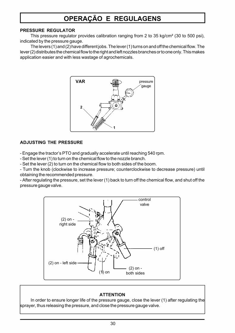
OPERAÇÃO E REGULAGENSPRESSURE REGULATOR
This pressure regulator provides calibration ranging from 2 to 35 kg/cm² (30 to 500 psi),indicated by the pressure gauge.
The levers (1) and (2) have different jobs. The lever (1) turns on and off the chemical flow. Thelever (2) distributes the chemical flow to the right and left nozzles branches or to one only. This makesapplication easier and with less wastage of agrochemicals.
ATTENTIONIn order to ensure longer life of the pressure gauge, close the lever (1) after regulating the
sprayer, thus releasing the pressure, and close the pressure gauge valve.
VAR pressuregauge
2
1
(1) on
(2) on - left side(2) on -
both sides
(1) off
controlvalve
(2) on -right side
ADJUSTING THE PRESSURE
- Engage the tractor’s PTO and gradually accelerate until reaching 540 rpm.- Set the lever (1) to turn on the chemical flow to the nozzle branch.- Set the lever (2) to turn on the chemical flow to both sides of the boom.- Turn the knob (clockwise to increase pressure; counterclockwise to decrease pressure) untilobtaining the recommended pressure.- After regulating the pressure, set the lever (1) back to turn off the chemical flow, and shut off thepressure gauge valve.
31
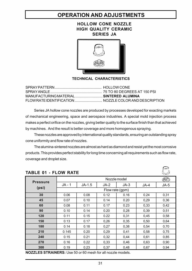
OPERATION AND ADJUSTMENTSHOLLOW CONE NOZZLEHIGH QUALITY CERAMIC
SERIES JA
TECHNICAL CHARACTERISTICS
SPRAY PATTERN .................................................. HOLLOW CONESPRAY ANGLE ....................................................... 75 TO 80 DEGREES AT 150 PSIMANUFACTURING MATERIAL .............................SINTERED ALUMINAFLOW RATE IDENTIFICATION ............................. NOZZLE COLOR AND DESCRIPTION
Series JA hollow cone nozzles are produced by processes developed for exacting markets
of mechanical engineering, space and aerospace industries. A special mold injection process
makes a perfect orifice on the nozzles, giving better quality to the surface finish than that achieved
by machines. And the result is better coverage and more homogenous spraying.
These nozzles are approved by international quality standards, ensuring an outstanding spray
cone uniformity and flow rate of nozzles.
The alumina-sintered nozzles are almost as hard as diamond and resist yet the most corrosive
products. This provides perfect stability for long time concerning all requirements such as flow rate,
coverage and droplet size.
NOZZLES STRAINERS: Use 50 or 60 mesh for all nozzle models.
TABLE 01 - FLOW RATE
30456090120150180210240270300
Pressure(psi) Flow rate (gpm)
JA - 1 JA-1.5 JA-2 JA-3 JA-4 JA-5
0,310,360,420,510,580,640,700,750,850,900,94
0.240,290,330,390,450,500,540,580,610,630,67
0.160.200.230,280,310,350,380,410,440,460,48
0.120.140.170.200.220,260,270,290,320,330,37
0.080.100.110.140.150.170.180.200.210.220.23
0.060.070.080.100.110.130.140.1450.150.160.19
Nozzle model
32
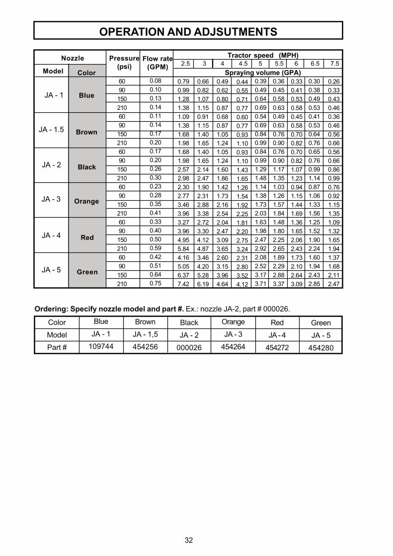
OPERATION AND ADJSUTMENTS
Tractor speed (MPH) 2.5 3 4 4.5 5 5.5 6 6.5 7.5
Spraying volume (GPA)0.790.991.281.381.091.381.681.981.681.982.572.982.302.773.463.963.273.964.955.844.165.056.377.42
0.660.821.071.150.911.151.401.651.401.652.142.471.902.312.883.382.723.304.124.873.464.205.286.19
0.490.620.800.870.680.871.051.241.051.241.601.861.421.732.162.542.042.473.093.652.603.153.964.64
0.390.490.640.690.540.690.840.990.840.991.291.481.141.381.732.031.631.982.472.922.082.523.173.71
0.360.450.580.630.490.630.760.900.760.901.171.351.031.261.571.841.481.802.252.651.892.292.883.37
0.330.410.530.580.450.580.700.820.700.821.071.230.941.151.441.691.361.652.062.431.732.102.643.09
0.300.380.490.530.410.530.640.760.650.760.991.140.871.061.331.561.251.521.902.241.601.942.432.85
0.260.330.430.460.360.460.560.660.560.660.860.990.760.921.151.351.091.321.651.941.371.682.112.47
Flow rate(GPM)
0.080.100.130.140.110.140.170.200.170.200.260.300.230.280.350.410.330.400.500.590.420.510.640.75
Pressure(psi)
Nozzle
Model Color
JA - 1
JA - 1.5
JA - 2
JA - 3
JA - 5
JA - 4
Brown
Black
Orange
Green
Red
Blue
609015021060901502106090150210609015021060901502106090150210
Color
Model
Part #
Brown
JA - 1,5
454256
Black
JA - 2
000026
Orange
JA - 3
454264
Red
JA - 4
454272
Green
JA - 5
454280
Ordering: Specify nozzle model and part #. Ex.: nozzle JA-2, part # 000026.
Blue
JA - 1
109744
0.440.550.710.770.600.770.931.100.931.101.431.651.261.541.922.251.812.202.753.242.312.803.524.12
33
OPERATION AND ADJUSTMENTS
Specify nozzle model and part #. Ex: J5-2, part # 325431.
Nozzle model
Part #
ORDERING
J4 - 2
325423
J4 - 3
819607
J5 - 2
325431
J5 - 3
327486
J6 - 2
325449
J6 - 3
327494
Ring
913335
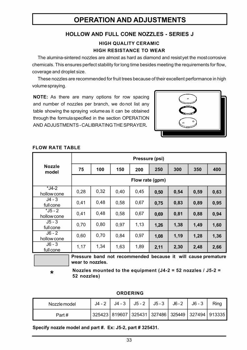
HIGH QUALITY CERAMICHIGH RESISTANCE TO WEAR
The alumina-sintered nozzles are almost as hard as diamond and resist yet the most corrosivechemicals. This ensures perfect stability for long time besides meeting the requirements for flow,coverage and droplet size.
These nozzles are recommended for fruit trees because of their excellent performance in highvolume spraying.
HOLLOW AND FULL CONE NOZZLES - SERIES J
Pressure band not recommended because it will cause prematurewear to nozzles.
NOTE: As there are many options for row spacingand number of nozzles per branch, we do not list anytable showing the spraying volume as it can be obtainedthrough the formula specified in the section OPERATIONAND ADJUSTMENTS - CALIBRATING THE SPRAYER.
Nozzles mounted to the equipment (J4-2 = 52 nozzles / J5-2 =52 nozzles)
Flow rate (gpm)
Pressure (psi)
75 100 150 200 250 300 350 400
FLOW RATE TABLE
*J4-2hollow cone
J4 - 3full cone*J5 - 2
hollow coneJ5 - 3
full coneJ6 - 2
hollow coneJ6 - 3
full cone
Nozzlemodel
0,28
0,41
0,41
0,70
0,60
1,17
0,32
0,48
0,48
0,80
0,70
1,34
0,40
0,58
0,58
0,97
0,84
1,63
0,45
0,67
0,67
1,13
0,97
1,89
0,63
0,95
0,94
1,60
1,36
2,66
0,50
0,75
0,69
1,26
1,08
2,11
0,54
0,83
0,81
1,38
1,19
2,30
0,59
0,89
0,88
1,49
1,28
2,48
*
34
OPERATION AND ADJUSTMENTS
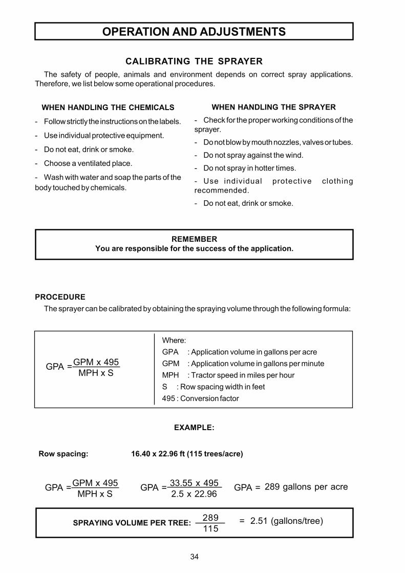
289115
= 2.51 (gallons/tree)SPRAYING VOLUME PER TREE:
CALIBRATING THE SPRAYERThe safety of people, animals and environment depends on correct spray applications.
Therefore, we list below some operational procedures.
WHEN HANDLING THE SPRAYER- Check for the proper working conditions of thesprayer.
- Do not blow by mouth nozzles, valves or tubes.
- Do not spray against the wind.
- Do not spray in hotter times.
- Use individual protective clothingrecommended.
- Do not eat, drink or smoke.
REMEMBERYou are responsible for the success of the application.
Where:GPA : Application volume in gallons per acreGPM : Application volume in gallons per minuteMPH : Tractor speed in miles per hourS : Row spacing width in feet495 : Conversion factor
PROCEDUREThe sprayer can be calibrated by obtaining the spraying volume through the following formula:
WHEN HANDLING THE CHEMICALS
- Follow strictly the instructions on the labels.
- Use individual protective equipment.
- Do not eat, drink or smoke.
- Choose a ventilated place.
- Wash with water and soap the parts of thebody touched by chemicals.
GPM x 495MPH x S
GPA =
Row spacing: 16.40 x 22.96 ft (115 trees/acre)
EXAMPLE:
GPM x 495MPH x S
GPA = 33.55 x 4952.5 x 22.96
GPA = 289 gallons per acreGPA =
35
OPERATION AND ADJUSTMENTS
PREPARING THE CHEMICAL MIXTURE
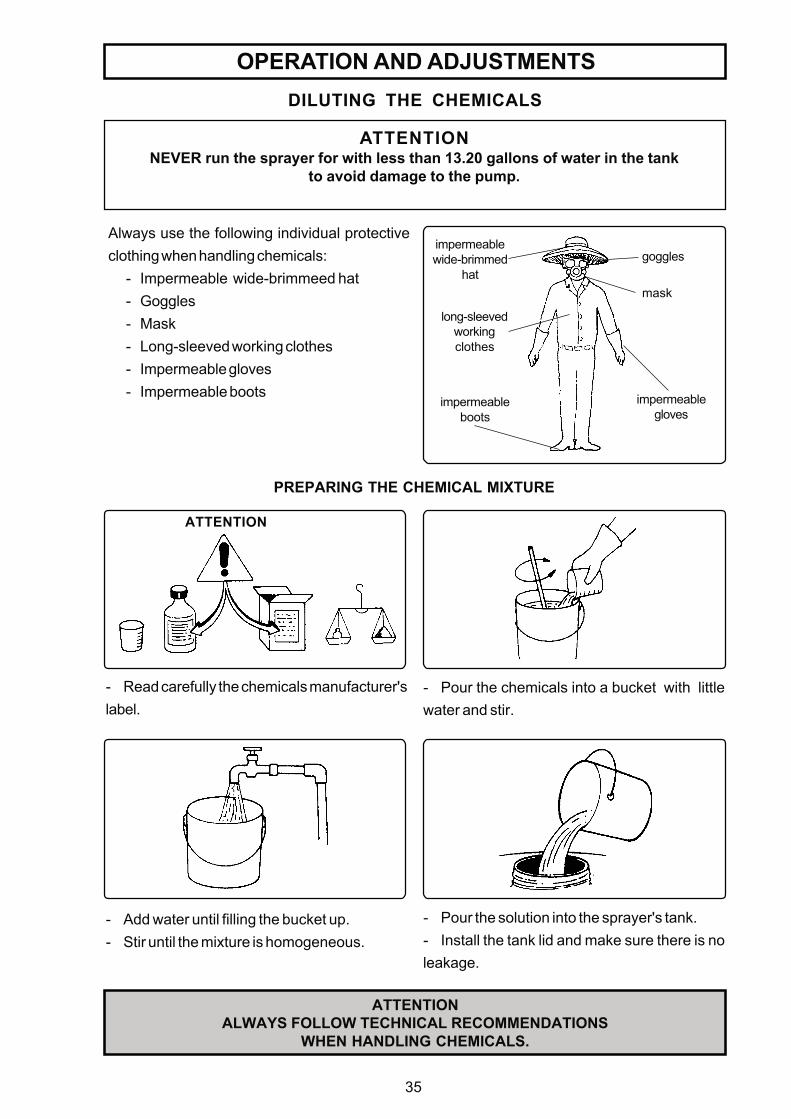
ATTENTIONALWAYS FOLLOW TECHNICAL RECOMMENDATIONS
WHEN HANDLING CHEMICALS.
Always use the following individual protectiveclothing when handling chemicals:
- Impermeable wide-brimmeed hat- Goggles- Mask- Long-sleeved working clothes- Impermeable gloves- Impermeable boots
ATTENTIONNEVER run the sprayer for with less than 13.20 gallons of water in the tank
to avoid damage to the pump.
DILUTING THE CHEMICALS
goggles
mask
ATTENTION
- Read carefully the chemicals manufacturer'slabel.
- Pour the chemicals into a bucket with littlewater and stir.
- Add water until filling the bucket up.- Stir until the mixture is homogeneous.
- Pour the solution into the sprayer's tank.- Install the tank lid and make sure there is noleakage.
long-sleevedworkingclothes
impermeablewide-brimmed
hat
impermeableboots
impermeablegloves
36
on
off
OPERATION AND ADJUSTMENTS
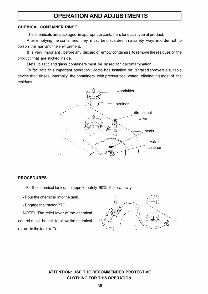
CHEMICAL CONTAINER RINSE
- Pour the chemical into the tank.
- Engage the tractor PTO.
NOTE: The relief lever of the chemical
control must be set to allow the chemical
return to the tank (off).
ATTENTION: USE THE RECOMMENDED PROTECTIVECLOTHING FOR THIS OPERATION.
The chemicals are packaged in appropriate containers for each type of product.After emptying the containers, they must be discarded in a safety way, in order not to
poison the man and the environment.It is very important , before any discard of empty containers, to remove the residues of the
product that are sticked inside.Metal, plastic and glass containers must be rinsed for decontamination.To facilitate this important operation , Jacto has installed on its trailed sprayers a suitable
device that rinses internally the containers with pressurized water, eliminating most of theresidues.
PROCEDURES
sprinkler
strainer
directionalvalve
valvefastener
seals
- Fill the chemical tank up to approximately 90% of its capacity.
37
chemicalcontainer
chemicalcontainer
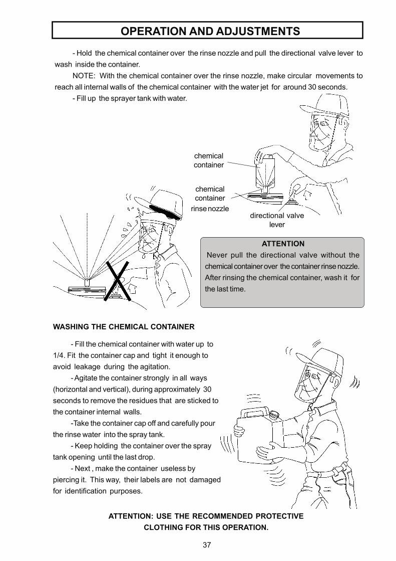
rinse nozzledirectional valve
lever
- Hold the chemical container over the rinse nozzle and pull the directional valve lever towash inside the container.
NOTE: With the chemical container over the rinse nozzle, make circular movements toreach all internal walls of the chemical container with the water jet for around 30 seconds.
- Fill up the sprayer tank with water.
OPERATION AND ADJUSTMENTS
- Fill the chemical container with water up to1/4. Fit the container cap and tight it enough toavoid leakage during the agitation.
- Agitate the container strongly in all ways(horizontal and vertical), during approximately 30seconds to remove the residues that are sticked tothe container internal walls.
-Take the container cap off and carefully pourthe rinse water into the spray tank.
- Keep holding the container over the spraytank opening until the last drop.
- Next , make the container useless bypiercing it. This way, their labels are not damagedfor identification purposes.
WASHING THE CHEMICAL CONTAINER
ATTENTIONNever pull the directional valve without thechemical container over the container rinse nozzle.After rinsing the chemical container, wash it forthe last time.
ATTENTION: USE THE RECOMMENDED PROTECTIVECLOTHING FOR THIS OPERATION.
38
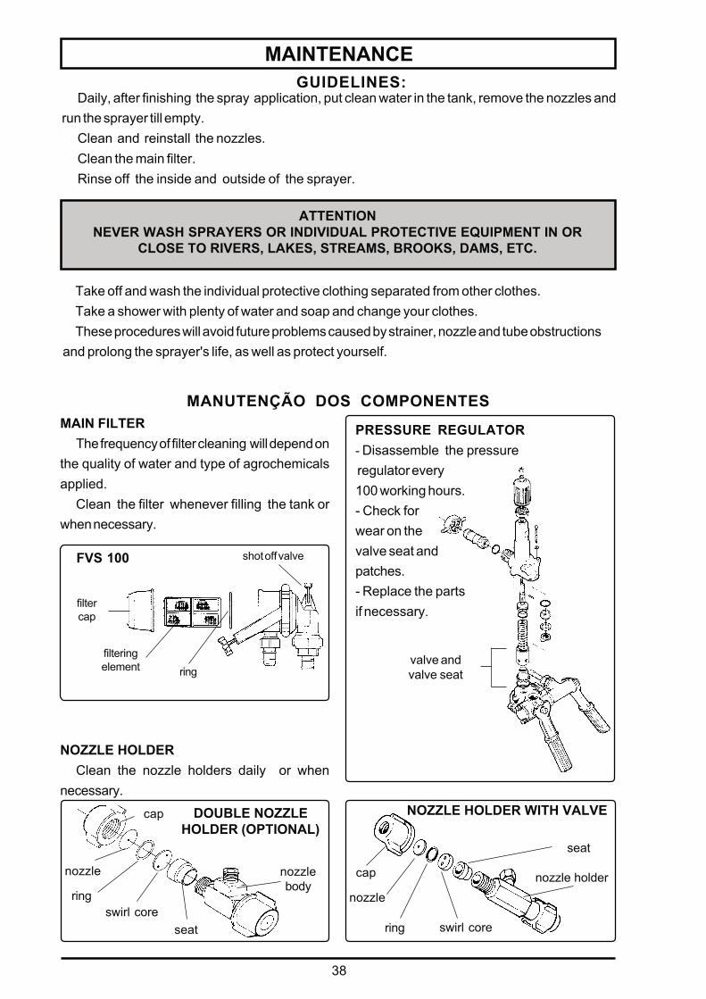
PRESSURE REGULATOR- Disassemble the pressure regulator every100 working hours.- Check forwear on thevalve seat andpatches.- Replace the partsif necessary.
MAIN FILTERThe frequency of filter cleaning will depend on
the quality of water and type of agrochemicalsapplied.
Clean the filter whenever filling the tank orwhen necessary.
DOUBLE NOZZLEHOLDER (OPTIONAL)
MANUTENÇÃO DOS COMPONENTES
seat
nozzle holder
NOZZLE HOLDER WITH VALVE
cap
nozzle
ring swirl core
valve andvalve seat
seatswirl core
ring
nozzle
cap
nozzlebody
filtercap
shot off valve
ringfilteringelement
FVS 100
NOZZLE HOLDERClean the nozzle holders daily or when
necessary.
MAINTENANCE
Daily, after finishing the spray application, put clean water in the tank, remove the nozzles andrun the sprayer till empty.
Clean and reinstall the nozzles.Clean the main filter.Rinse off the inside and outside of the sprayer.
GUIDELINES:
ATTENTIONNEVER WASH SPRAYERS OR INDIVIDUAL PROTECTIVE EQUIPMENT IN OR
CLOSE TO RIVERS, LAKES, STREAMS, BROOKS, DAMS, ETC.
Take off and wash the individual protective clothing separated from other clothes.Take a shower with plenty of water and soap and change your clothes.These procedures will avoid future problems caused by strainer, nozzle and tube obstructions
and prolong the sprayer's life, as well as protect yourself.
39
MAINTENANCE
COMPONENTS LUBRICATION
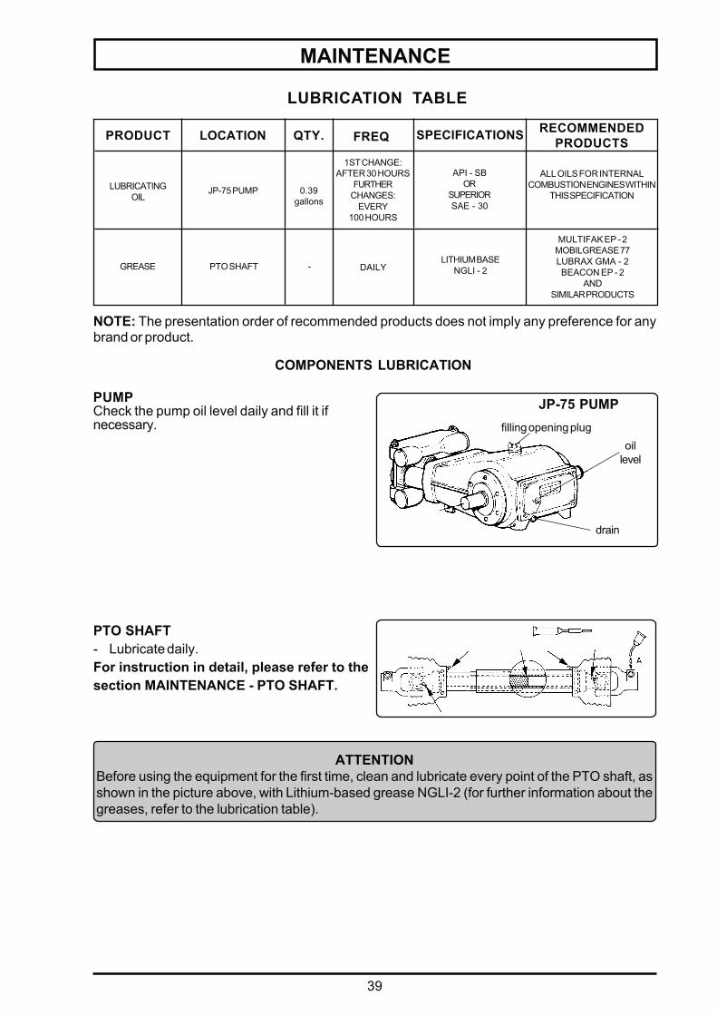
PUMPCheck the pump oil level daily and fill it ifnecessary.
JP-75 PUMPfilling opening plug
oillevel
drain
LUBRICATION TABLE
FREQRECOMMENDED
PRODUCTSSPECIFICATIONSQTY.PRODUCT LOCATION
JP-75 PUMP 0.39gallons
API - SBOR
SUPERIORSAE - 30
-PTO SHAFT DAILYLITHIUM BASE
NGLI - 2
MULTIFAK EP - 2MOBILGREASE 77LUBRAX GMA - 2BEACON EP - 2
ANDSIMILAR PRODUCTS
GREASE
1ST CHANGE:AFTER 30 HOURS
FURTHERCHANGES:
EVERY100 HOURS
ALL OILS FOR INTERNALCOMBUSTION ENGINES WITHIN
THIS SPECIFICATIONLUBRICATING
OIL
NOTE: The presentation order of recommended products does not imply any preference for anybrand or product.
PTO SHAFT- Lubricate daily.For instruction in detail, please refer to thesection MAINTENANCE - PTO SHAFT.
ATTENTIONBefore using the equipment for the first time, clean and lubricate every point of the PTO shaft, asshown in the picture above, with Lithium-based grease NGLI-2 (for further information about thegreases, refer to the lubrication table).
40
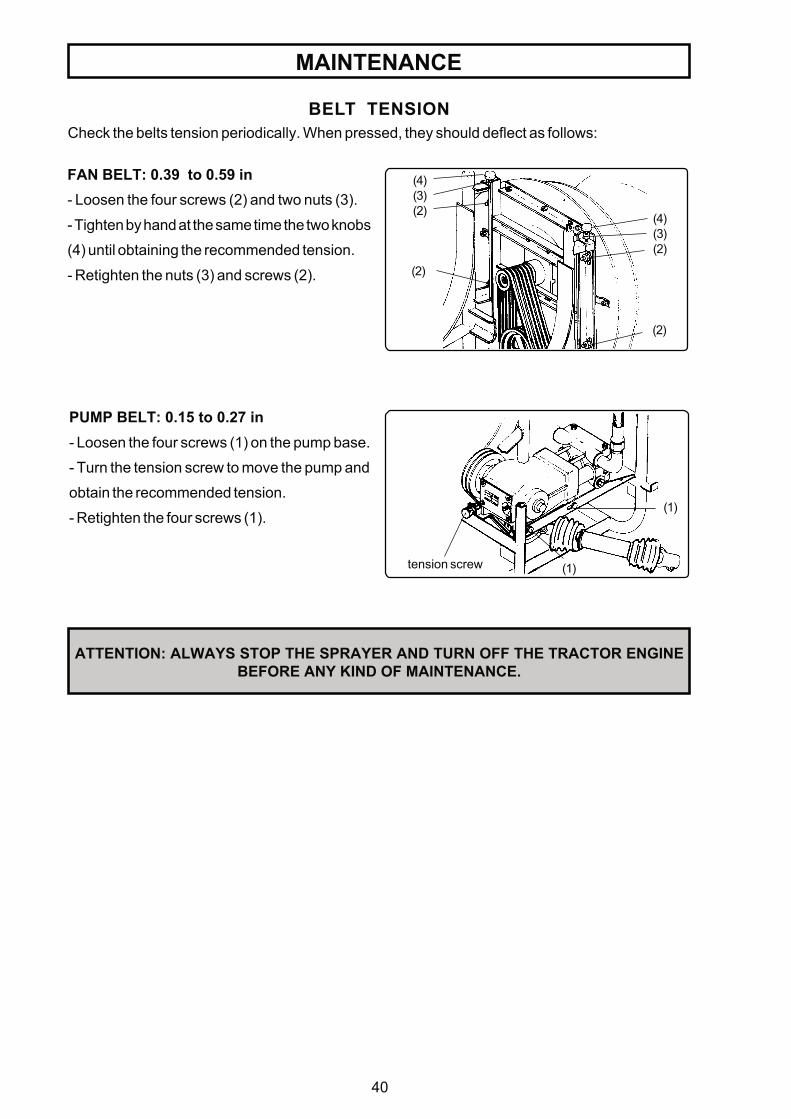
BELT TENSIONCheck the belts tension periodically. When pressed, they should deflect as follows:
ATTENTION: ALWAYS STOP THE SPRAYER AND TURN OFF THE TRACTOR ENGINEBEFORE ANY KIND OF MAINTENANCE.
PUMP BELT: 0.15 to 0.27 in- Loosen the four screws (1) on the pump base.
- Turn the tension screw to move the pump and
obtain the recommended tension.
- Retighten the four screws (1).
FAN BELT: 0.39 to 0.59 in- Loosen the four screws (2) and two nuts (3).
- Tighten by hand at the same time the two knobs
(4) until obtaining the recommended tension.
- Retighten the nuts (3) and screws (2).
tension screw
(1)
(1)
(4)(3)(2) (4)
(3)(2)
(2)
(2)
MAINTENANCE
41
MAINTENANCE
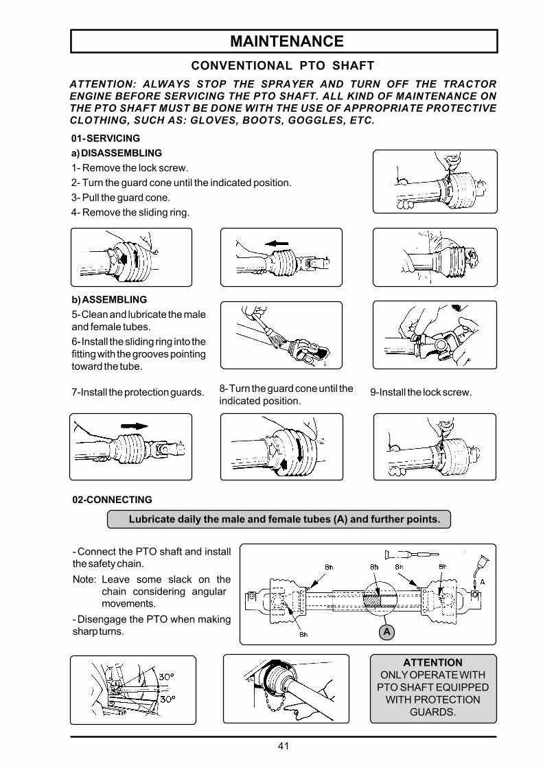
-Connect the PTO shaft and installthe safety chain.Note: Leave some slack on the
chain considering angularmovements.
-Disengage the PTO when makingsharp turns.
01- SERVICINGa) DISASSEMBLING1- Remove the lock screw.2- Turn the guard cone until the indicated position.3- Pull the guard cone.4- Remove the sliding ring.
b) ASSEMBLING5-Clean and lubricate the maleand female tubes.6-Install the sliding ring into thefitting with the grooves pointingtoward the tube.
7-Install the protection guards. 8-Turn the guard cone until theindicated position.
9-Install the lock screw.
02-CONNECTING
Lubricate daily the male and female tubes (A) and further points.
ATTENTION: ALWAYS STOP THE SPRAYER AND TURN OFF THE TRACTORENGINE BEFORE SERVICING THE PTO SHAFT. ALL KIND OF MAINTENANCE ONTHE PTO SHAFT MUST BE DONE WITH THE USE OF APPROPRIATE PROTECTIVECLOTHING, SUCH AS: GLOVES, BOOTS, GOGGLES, ETC.
CONVENTIONAL PTO SHAFT
A
ATTENTIONONLY OPERATE WITH
PTO SHAFT EQUIPPEDWITH PROTECTION
GUARDS.
42
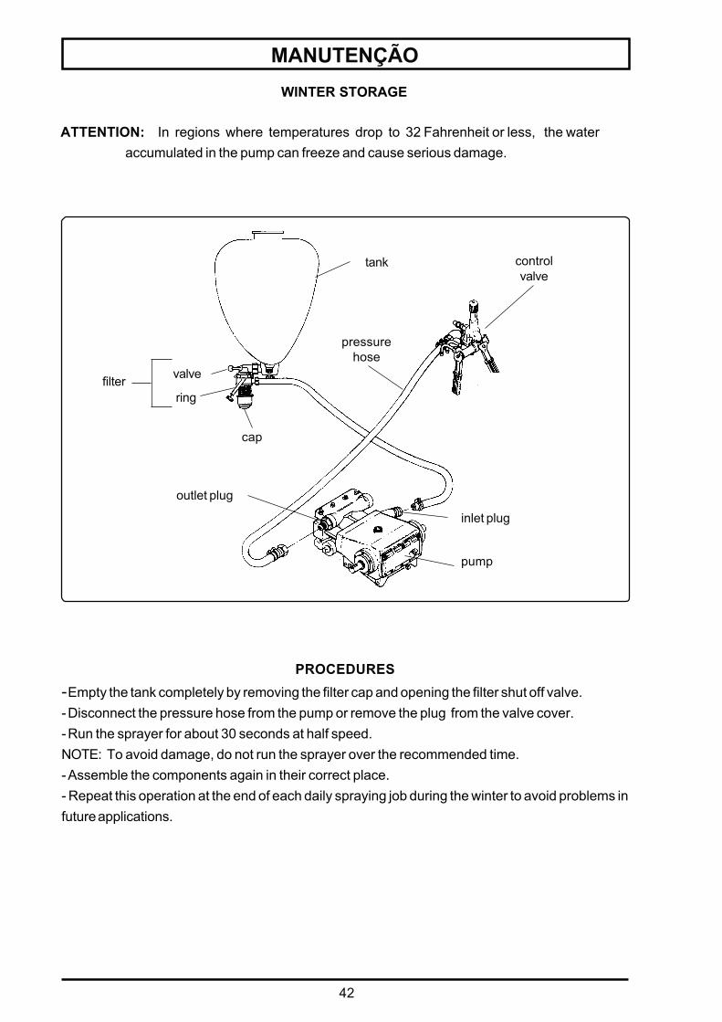
WINTER STORAGE
ATTENTION: In regions where temperatures drop to 32 Fahrenheit or less, the wateraccumulated in the pump can freeze and cause serious damage.
MANUTENÇÃO
PROCEDURES-Empty the tank completely by removing the filter cap and opening the filter shut off valve.-Disconnect the pressure hose from the pump or remove the plug from the valve cover.-Run the sprayer for about 30 seconds at half speed.NOTE: To avoid damage, do not run the sprayer over the recommended time.-Assemble the components again in their correct place.- Repeat this operation at the end of each daily spraying job during the winter to avoid problems infuture applications.
tank
pressurehose
inlet plug
outlet plug
pump
valve
ring
cap
filter
controlvalve
43
MAINTENANCE
COMPONENTS:
-Tank
-Main tank
-Control valve
-Pump
-Pressure hose
-Return hose
-Nozzles
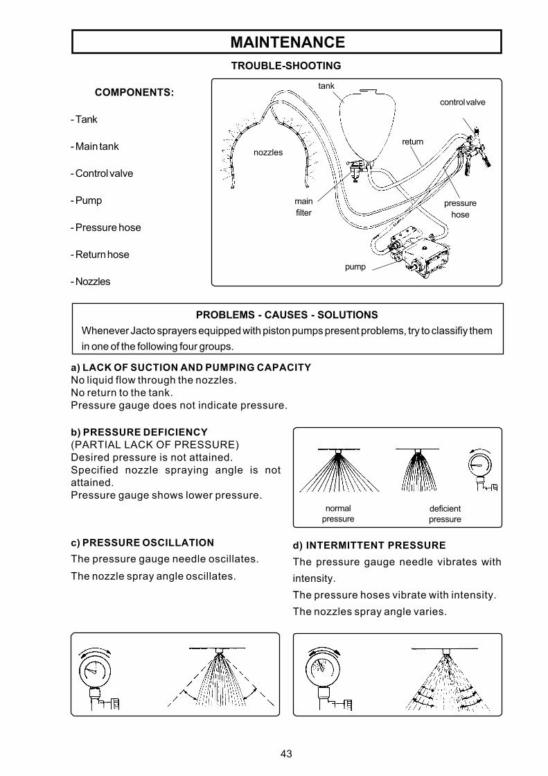
TROUBLE-SHOOTING
nozzles
control valve
mainfilter
return
pump
tank
pressurehose
PROBLEMS - CAUSES - SOLUTIONSWhenever Jacto sprayers equipped with piston pumps present problems, try to classifiy themin one of the following four groups.
a) LACK OF SUCTION AND PUMPING CAPACITYNo liquid flow through the nozzles.No return to the tank.Pressure gauge does not indicate pressure.
b) PRESSURE DEFICIENCY(PARTIAL LACK OF PRESSURE)Desired pressure is not attained.Specified nozzle spraying angle is notattained.Pressure gauge shows lower pressure.
deficientpressure
normalpressure
c) PRESSURE OSCILLATIONThe pressure gauge needle oscillates.The nozzle spray angle oscillates.
d) INTERMITTENT PRESSUREThe pressure gauge needle vibrates withintensity.The pressure hoses vibrate with intensity.The nozzles spray angle varies.
44
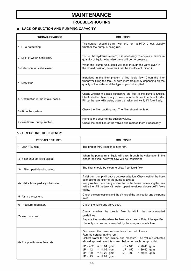
TROUBLE-SHOOTING
MAINTENANCE
1- PTO not turning.The sprayer should be run with 540 rpm at PTO. Check visuallywhether the pump is being run.
To run the hydraulic system, it is necessary to contain a minimumquantity of liquid, otherwise there will be no pressure.
When the pump runs, liquid will pass through the valve even inthe closed position, however it will be insufficient. Open it.
Impurities in the filter prevent a free liquid flow. Clean the filterwhenever filling the tank, or with more frequency depending on thequality of the water and the type of product applied.
Check whether the hose connecting the filter to the pump is twisted.Check whether there is any obstruction in the hoses from tank to filter.Fill up the tank with water, open the valve and verify if it flows freely.
Check the filter packing ring. The filter should not leak.
Remove the cover of the suction valves.Check the condition of the valves and replace them if necessary.
3- Filter shut off valve closed.
4- Dirty filter.
2- Lack of water in the tank.
5- Obstruction in the intake hoses.
6- Air in the system.
7- Insufficient pump suction.
PROBABLE CAUSES SOLUTIONS
a - LACK OF SUCTION AND PUMPING CAPACITY
PROBABLE CAUSES SOLUTIONS
b - PRESSURE DEFICIENCY
The proper PTO rotation is 540 rpm.1- Low PTO rpm.
When the pumps runs, liquid will pass through the valve even in theclosed position, however flow will be insufficient.
The filter should be clean to allow free liquid flow.
A deficient pump will cause depressurization. Check wether the hoseconnecting the filter to the pump is twisted.Verify wether there is any obstruction in the hoses connecting the tankto the filter. Fill the tank with water, open the valve and observe if it flowsfreely.
Check the connections and the o'rings of the tank outlet and the pumpinlet.
Check whether the nozzle flow is within the recommendedguidelines.Replace the nozzles when the flow rate exceeds 10% of the specified.Use only nozzles recommended by the sprayer manufacturer.
Check the valve and valve seat.
2- Filter shut off valve closed.
3- Filter partially obstructed.
4- Intake hose partially obstructed.
5- Air in the system.
6- Pressure regulator.
7- Worn nozzles.
8- Pump with lower flow rate.
Disconnect the pressure hose from the control valve.Run the sprayer at 540 rpm.Collect water for one minute and measure. The volume collectedshould approximate this shown below for each pump model:
JP - 100 = 26.41 gpmJP - 150 = 39.62 gpmJP - 300 = 79.25 gpm
JP - 402 = 10.04 gpmJP - 42 = 11.09 gpmJP - 50 = 13.20 gpmJP - 75 = 19.81 gpm
45
MAINTENANCE
SOLUTIONSPROBABLE CAUSES
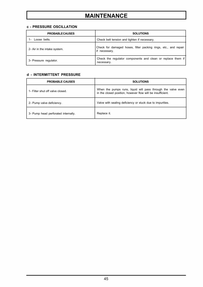
Check belt tension and tighten if necessary.1- Loose belts.
Check for damaged hoses, filter packing rings, etc., and repairif necessary.2- Air in the intake system.
Check the regulator components and clean or replace them ifnecessary.3- Pressure regulator.
c - PRESSURE OSCILLATION
PROBABLE CAUSES SOLUTIONS
1- Filter shut off valve closed.
d - INTERMITTENT PRESSURE
2- Pump valve deficiency.
3- Pump head perforated internally.
Valve with sealing deficiency or stuck due to impurities.
Replace it.
When the pumps runs, liquid will pass through the valve evenin the closed position, however flow will be insufficient.
46
HANDLING AGRICULTURAL SPRAYERS AND CHEMICALS
We warn the owners and users that the UNREASONABLE USE of this sprayer and chemicals
applied may cause damage to people, properties, animals and environment.
Read carefully and understand thoroughly this manual and the recommendations of the
chemicals manufacturers.
Follow strictly the instructions for proper use of this sprayer and chemicals to ensure more safety
and efficiency when spraying your crops.
AFTER SPRAYING
ATTENTION: Avoid leaving chemical mixture residues in the tank. For the last pass, prepare
the chemical solution in enough quantity to spray the remaining of the crop.
- Empty completely the tank and wash thoroughly the sprayer in a proper decontamination
place.
- Wash the inside and outside of the sprayer with clean water and detergent.
- Disassemble and clean each nozzle assembly with fine brush, water jet or compressed air.
- Dry, lubricate and store the sprayer in a dry and covered place.
- Repaint the damaged metallic parts to prevent corrosion.
- Spray the mettalic parts with lubricating oil to prevent corrosion.
- Take off and wash the individual protective clothing separately from other clothes.
DANGERSAFETY OBSERVATION
OPERATING THIS SPRAYER WITHOUT FOLLOWING THE INSTRUCTIONSMAY RESULT IN SERIOUS INJURY OR DEATH.
GENERAL CARE
47
MÁQUINAS AGRÍCOLAS JACTO S.A. warrants the equipment described herein and agrees to repairor replace parts and components which, under normal operation and wear, following the technicalrecommendations, show DEFECTS IN MATERIAL OR WORKMANSHIP.WARRANTY PERIOD:- One (1) year from the purchase date by the original retail purchaser.
WARRANTY APPLICATION:Jacto or its authorized representative shall honor this warranty, if any part or component shows confirmeddefect in workmanship.IT SHALL BE UNDERSTOOD THAT THE REPLACEMENT OF COMPLETE COMPONENTS SUCH ASPUMPS, CONTROL VALVES, ENGINES, TRANSMISSIONS, HYDRAULIC PISTONS AND SIMILARONES SHALL ONLY BE PERFORMED IN CASE THAT THE DEFECT CANNOT BE REPAIRED BYREPLACING PARTS AND/OR PIECES OF THE COMPONENT.
THIS WARRANTY IS NULL AND VOID IF:- Equipment is not used in accordance with the INSTRUCTION MANUAL, overwork or accidents.- Improper preventive maintenance or performed by unauthorized people.- Modification of the equipment in any way from the original design.- Change, damage, or loss of the product identification plate.- Utilization of parts and components not supplied by JACTO.
PRODUCT REGISTRATION CARD MUST BE COMPLETED BY THE ORIGINAL RETAILPURCHASER, AND RETURNED TO JACTO DEALER WITHIN 30 DAYS OF PURCHASE DATE.
WARRANTY EXCLUSIONS:- Parts considered as normal maintenance such as: filtering elements, belts, hoses, nozzles, pistons,
pressure gauges, as well as usual maintenance, adjustments, retightening, lubrication and painting.- Parts which show wear or tear due to use, UNLESS THEY SHOW DEFECTS IN WORKMANSHIP,
ASSEMBLY OR MATERIAL.- Hydraulic, lubricating oils and grease.- Injuries of personal or material nature to the user, owner, or third parties.- Additional charges resulting from paralyzation and repair of the equipment.- Freight charges, pick up and delivery charges.- Damages of any nature resulting from action of gases or liquids used in the equipment.
GENERAL INFORMATION:- Defective parts replaced under warranty period shall be property of JACTO.- Eventual delays in performing services do not confer to the owner the right to indemnity or to extension
of the warranty period.- JACTO reserves the right to change its products or to interrupt manufacturing the equipment.- THIS LIMITED WARRANTY shall be understood by its expressed terms, and no one in anyway subject
to JACTO shall be authorized to modify or amplify the conditions prescribed herein.- In case of need for warranty request, call for the authorized dealer supplying all information required for
a prompt compliance. Do not forget the identification of the equipment, total hours of work, and thenoticed defect.
FOR THIS WARRANTY TO BECOME EFFECTIVE THE PRODUCT REGISTRATION CARD FOUNDIN THE INSTRUCTION MANUAL MUST BE FILLED IN AND RETURNED TO YOUR JACTO DEALER.THIS CARD MUST BE SIGNED BY THE ORIGINAL RETAIL PURCHASER, INDICATING THAT HE HASREAD AND UNDERSTOOD ALL SAFETY AND OPERATIONAL INSTRUCTIONS IN THE MANUAL.FURTHER THE RETAILING DEALER HAS EXPLAINED TO THE ORIGINAL RETAIL PURCHASER ALLSAFETY INSTRUCTIONS. IN NO CASE WILL WARRANTY BE SUPPLIED UNTIL THIS CARD, PROPERLYCOMPLETED AND SIGNED, IS ON FILE WITH JACTO RETAILING DEALER.
STATEMENT OF LIMITED WARRANTY

49
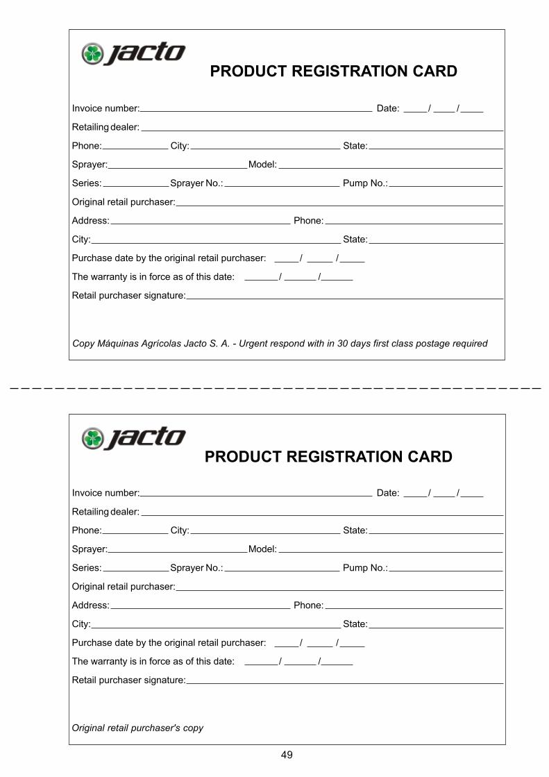
PRODUCT REGISTRATION CARD
Copy Máquinas Agrícolas Jacto S. A. - Urgent respond with in 30 days first class postage required
Original retail purchaser's copy
PRODUCT REGISTRATION CARD
Invoice number: Date: / /
Retailing dealer:
Phone: City: State:
Sprayer: Model:
Series: Sprayer No.: Pump No.:
Original retail purchaser:
Address: Phone:
City: State:
Purchase date by the original retail purchaser: / /
The warranty is in force as of this date: / /
Retail purchaser signature:
Invoice number: Date: / /
Retailing dealer:
Phone: City: State:
Sprayer: Model:
Series: Sprayer No.: Pump No.:
Original retail purchaser:
Address: Phone:
City: State:
Purchase date by the original retail purchaser: / /
The warranty is in force as of this date: / /
Retail purchaser signature: