ar6000 command list - aor · all the control commands for the lan interface are the same as the usb...
TRANSCRIPT
®
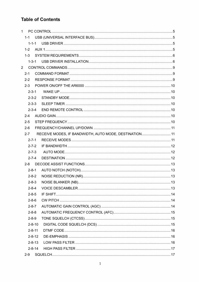
AR6000 Super Wide-band
Multi-mode Receiver
Command list
AOR, LTD.
1
Table of Contents
1 PC CONTROL ............................................................................................................................. 5
1-1 USB (UNIVERSAL INTERFACE BUS) ................................................................................. 5
1-1-1 USB DRIVER ................................................................................................................. 5
1-2 AUX 1 .................................................................................................................................... 5
1-3 SYSTEM REQUIREMENTS ................................................................................................. 6
1-3-1 USB DRIVER INSTALLATION ....................................................................................... 6
2 CONTROL COMMANDS ............................................................................................................. 9
2-1 COMMAND FORMAT ........................................................................................................... 9
2-2 RESPONSE FORMAT .......................................................................................................... 9
2-3 POWER ON/OFF THE AR6000 ......................................................................................... 10
2-3-1 WAKE UP ................................................................................................................... 10
2-3-2 STANDBY MODE ......................................................................................................... 10
2-3-3 SLEEP TIMER ............................................................................................................. 10
2-3-4 END REMOTE CONTROL .......................................................................................... 10
2-4 AUDIO GAIN ....................................................................................................................... 10
2-5 STEP FREQUENCY ........................................................................................................... 10
2-6 FREQUENCY/CHANNEL UP/DOWN ................................................................................ 11
2-7 RECEIVE MODES, IF BANDWIDTH, AUTO MODE, DESTINATION .............................. 11
2-7-1 RECEIVE MODES ....................................................................................................... 11
2-7-2 IF BANDWIDTH ........................................................................................................... 12
2-7-3 AUTO MODE.............................................................................................................. 12
2-7-4 DESTINATION ............................................................................................................. 12
2-8 DECODE ASSIST FUNCTIONS ......................................................................................... 13
2-8-1 AUTO NOTCH (NOTCH) ............................................................................................. 13
2-8-2 NOISE REDUCTION (NR) ........................................................................................... 13
2-8-3 NOISE BLANKER (NB)................................................................................................ 13
2-8-4 VOICE DESCAMBLER ................................................................................................ 13
2-8-5 IF SHIFT ....................................................................................................................... 14
2-8-6 CW PITCH ................................................................................................................... 14
2-8-7 AUTOMATIC GAIN CONTROL (AGC) ........................................................................ 14
2-8-8 AUTOMATIC FREQUENCY CONTROL (AFC) ........................................................... 15
2-8-9 TONE SQUELCH (CTCSS) ......................................................................................... 15
2-8-10 DIGITAL CODE SQUELCH (DCS) ............................................................................ 15
2-8-11 DTMF CODE .............................................................................................................. 16
2-8-12 DE-EMPHASIS .......................................................................................................... 16
2-8-13 LOW PASS FILTER ................................................................................................... 16
2-8-14 HIGH PASS FILTER .................................................................................................. 17
2-9 SQUELCH ........................................................................................................................... 17
2
2-9-1 LEVEL SQUELCH (RQ COMMAND) .......................................................................... 17
2-9-2 LEVEL SQUELCH (HQ COMMAND) .......................................................................... 17
2-9-3 VOICE SQUELCH ....................................................................................................... 18
2-9-4 NOISE SQUELCH (NQ COMMAND) .......................................................................... 18
2-9-5 NOISE SQUELCH (QN COMMAND) .......................................................................... 18
2-9-6 NOISE SQUELCH ON/OFF ...................................................................................... 18
2-10 RF AMPLIFIER, ATTENUATOR ....................................................................................... 18
2-11 ANTENNA SELECT .......................................................................................................... 19
2-12 ANTENNA SELECT PROGRAMMING ............................................................................ 19
2-12-1 PROGRAMMING ....................................................................................................... 19
2-12-2 DELETING PROGRAM ............................................................................................. 19
2-13 S-METER .......................................................................................................................... 20
2-13-1 SIGNAL LEVEL .......................................................................................................... 20
2-13-2 AUTO SIGNAL LEVEL REPORT ............................................................................... 20
2-14 AUDIO RECORDER CONTROL ...................................................................................... 21
2-14-1 CONTROL RELAY STATUS ...................................................................................... 21
2-14-2 CONTROL RELAY STATUS REPORT ...................................................................... 21
2-15 MANUAL RF GAIN ........................................................................................................... 21
2-16 RF BANDPASS FILTER (FOR BELOW 25 MHz)............................................................. 21
3 RECEIVE COMMANDS ............................................................................................................ 22
3-1 VFO MODE ......................................................................................................................... 22
3-2 RECEIVE MODE STATUS ................................................................................................. 22
3-2-1 RECEIVE STATUS AUTO REPORT ........................................................................... 22
3-3 VFO MODE NOISE SQUELCH (DB COMMAND) ............................................................. 23
3-4 VFO MODE VOICE SQUELCH (DA COMMAND) ............................................................. 23
3-5 SEARCH MODE ................................................................................................................. 23
3-5-1 NORMAL SEARCH ...................................................................................................... 23
3-5-2 VFO SEARCH .............................................................................................................. 23
3-5-3 SEARCH BANK ........................................................................................................... 24
3-5-4 PASS FREQUENCY .................................................................................................. 26
3-5-5 PASS FREQUENCY (PS COMMAND)........................................................................ 27
3-5-6 SEARCH FREQUENCY LIST ...................................................................................... 27
3-5-7 COPY SEARCH FREQUENCY LIST TO MEMORY BANK ........................................ 28
3-5-8 FFT SEARCH ............................................................................................................... 28
3-6 MEMORY CHANNEL.......................................................................................................... 29
3-6-1 MEMORY READ MODE .............................................................................................. 29
3-6-2 MEMORY CHANNEL SETTING (MR COMMAND) ..................................................... 30
3-6-3 MEMORY CHANNEL DATA READ (OUTPUT TO USB PORT) .................................. 30
3-6-4 MEMORY CHANNEL REGISTRATION STATUS ........................................................ 31
3-6-5 DELETE MEMORY CHANNEL ................................................................................... 31
3
3-6-6 DELETE MEMORY BANK ........................................................................................... 31
3-7 SCAN .................................................................................................................................. 31
3-7-1 START SCAN ............................................................................................................... 31
3-7-2 SCAN GROUP SETTING ............................................................................................ 32
3-7-3 MEMORY BANK LINK ON/OFF .................................................................................. 32
3-7-4 MEMORY BANK LINK ................................................................................................. 33
3-7-5 MODE SCAN ............................................................................................................... 33
3-7-6 SCAN MODE NOISE SQUELCH ................................................................................ 33
3-7-7 SCAN MODE VOICE SQUELCH ................................................................................ 33
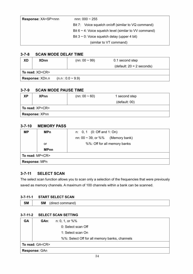
3-7-8 SCAN MODE DELAY TIME ......................................................................................... 34
3-7-9 SCAN MODE PAUSE TIME......................................................................................... 34
3-7-10 MEMORY PASS ......................................................................................................... 34
3-7-11 SELECT SCAN .......................................................................................................... 34
3-8 MULTI FREQUENCY RECEIVE ......................................................................................... 35
3-8-1 DUAL FREQUENCY RECEIVE (DUAL BAND RECEIVE MODE) .............................. 35
3-8-2 DUAL FREQUENCY RECEIVE (FREQUENCY OFFSET MODE) ............................. 36
3-8-3 TRIPLE FREQUENCY RECEIVE ................................................................................ 37
4 OTHER RECEIVE FUNCTIONS ............................................................................................... 37
4-1 PRIORITY RECEIVE .......................................................................................................... 37
4-1-1 PRIORITY SETUP ....................................................................................................... 37
4-1-2 STARTING PRIORITY RECEIVE ................................................................................ 37
4-2 STEP ADJUST .................................................................................................................... 38
4-3 SUB FREQUENCY STEP (FOR SUB DIAL) ...................................................................... 38
5 SPECTRUM DISPLAY ............................................................................................................... 38
5-1 START FREQUENCY ......................................................................................................... 38
5-2 END FREQUENCY ............................................................................................................. 38
5-3 CENTER FREQUENCY ..................................................................................................... 39
5-4 SPAN FREQUENCY ........................................................................................................... 39
5-5 SPECTRUM STEP FREQUENCY ..................................................................................... 39
5-6 MARKER FREQUENCY ..................................................................................................... 39
5-6-1 MARKER FREQUENCY .............................................................................................. 39
5-6-2 MARKER FREQUENCY / LEVEL AUTO OUTPUT ..................................................... 39
5-6-3 TRANSFER MARKER FREQUENCY TO RECEIVE FREQUENCY .......................... 39
5-7 SPECTRUM DATA OUTPUT .............................................................................................. 40
5-8 HIGH SPEED SPECTRUM DATA OUTPUT ...................................................................... 40
6 VIDEO FUNCTION .................................................................................................................... 40
6-1 VIDEO FUNCTION ............................................................................................................. 40
6-2 VIDEO IF REVERSE .......................................................................................................... 40
7 SD CARD ................................................................................................................................... 41
7-1 SD CARD INFORMATION .................................................................................................. 41
4
7-2 FILE DIRECTORY .............................................................................................................. 41
7-3 DELETE DATA FILE ........................................................................................................... 42
7-4 FORMAT SD CARD ............................................................................................................ 42
7-5 SQUELCH SKIP IN RECORD MODE ................................................................................ 42
7-6 RECORDING ...................................................................................................................... 42
7-7 PLAYBACK ......................................................................................................................... 43
7-8 OPERATION STATUS ........................................................................................................ 43
7-9 SEND MEMORY DATA TO SD CARD ............................................................................... 43
7-10 SEND SD MEMORY FILE TO AR6000 ............................................................................ 44
7-11 RENAME SD FILE NAMES .............................................................................................. 44
8 DATA EDITOR ........................................................................................................................... 45
9 CONFIGURATION SETTINGS OF OTHER PARAMETERS .................................................... 46
9-1 SELECTING INTERFACE .................................................................................................. 46
9-2 COMMUNICATION SPEED................................................................................................ 46
9-3 FLOW CONTROL ............................................................................................................... 46
10 OTHER CONTROL COMMANDS ........................................................................................... 47
10-1 PRODUCT VERSION ....................................................................................................... 47
10-2 RESET .............................................................................................................................. 47
10-3 FLASH MEMORY ............................................................................................................. 47
10-4 LEVEL SQUELCH HYSTERISIS ...................................................................................... 47
10-5 LCD BACKLIT ................................................................................................................... 47
10-6 BEEP LEVEL .................................................................................................................... 48
10-7 BEEP TONE...................................................................................................................... 48
10-8 CALENDER AND CLOCK ................................................................................................ 48
5
1 PC CONTROL
1-1 USB (UNIVERSAL INTERFACE BUS)
Connect the AR6000 to a PC using one of the remote control connectors.
The USB (type B) connector can connect directly to the PC’s USB port while the AUX 1
connector is able to connect to the RS-232C serial port.
The default setting is USB.
All functions of the AR6000 can be controlled by a PC.
1-1-1 USB DRIVER
To enable PC control, the USB driver for the AR6000 needs to be installed.
You can download the latest driver from the USB device manufacturer’s website at:
http://www.ftdichip.com/ftdrivers.htm
Click “VCP Drivers” and then select version corresponding to your operating system.
The following are the specifications for the communication protocol.
Communication speed: 115,200 bps (default), 57,600 bps, 38,400 bps, 19,200 bps, 9,600 bps
Data: 8 bit
Stop bit: 1
Parity: None
Flow control: None or RTS/CTS
Echo: Off
Return Code: (PC� AR6000): <CR>(0x0d) <LF> ignore
Return Code: (AR6000� PC): <CR><LF>(0x0d, 0x0a)
1-2 AUX 1
The AUX 1 is a serial port that uses a RS-232C cable terminated in a 9-pin connector.
The following are the specifications for the communication protocol.
Communication speed: 115,200 bps (default), 57,600 bps, 38,400 bps, 19,200 bps, 9,600 bps
Data: 8 bit
Stop bit: 1
Parity: None
Flow control: None or RTS/CTS
Echo: Off
With the optional LAN interface unit, the AR6000 can be controlled via the internet. All the control
commands for the LAN interface are the same as the USB control commands.
6
1-3 SYSTEM REQUIREMENTS
Hardware:
� PC with 2GHz Dual Core CPU with 1GB RAM
� USB Port (USB 2.0)
� 16 bit AC-97 compatible audio board
� 1024 x 768 (minimum) resolution video board and monitor
� 2 button mouse with wheel
� CD-ROM drive
Operating System:
� Windows® 2000 SP4, XP SP2 (32 bit version), WIN 7, WIN 8.
1-3-1 USB DRIVER INSTALLATION
1. Decompress the downloaded file into any location on your hard drive. (Example: Desktop, My
documents, etc.)
2. Connect the supplied AC adapter into the DC power input connector on the AR6000.
3. Connect the AC adapter to an electrical outlet and turn on the main power switch located on
the rear panel of the AR6000.
4. Turn on the power switch on the front panel.
5. Connect the square end of the USB cable (type B) into the USB connector on the rear panel
of the AR6000.
6. Connect the other end of the USB cable into an available USB port on the PC.
7. When the new hardware is found, the installation procedure begins.
8. Note: The sample screen instructions or messages shown below may differ depending on the
version of the Windows® operating system on your PC.
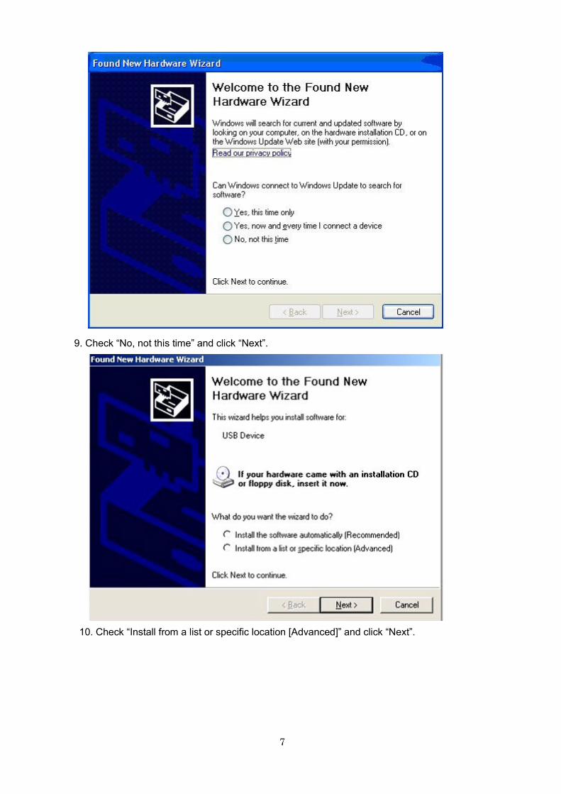
7
9. Check “No, not this time” and click “Next”.
10. Check “Install from a list or specific location [Advanced]” and click “Next”.
8
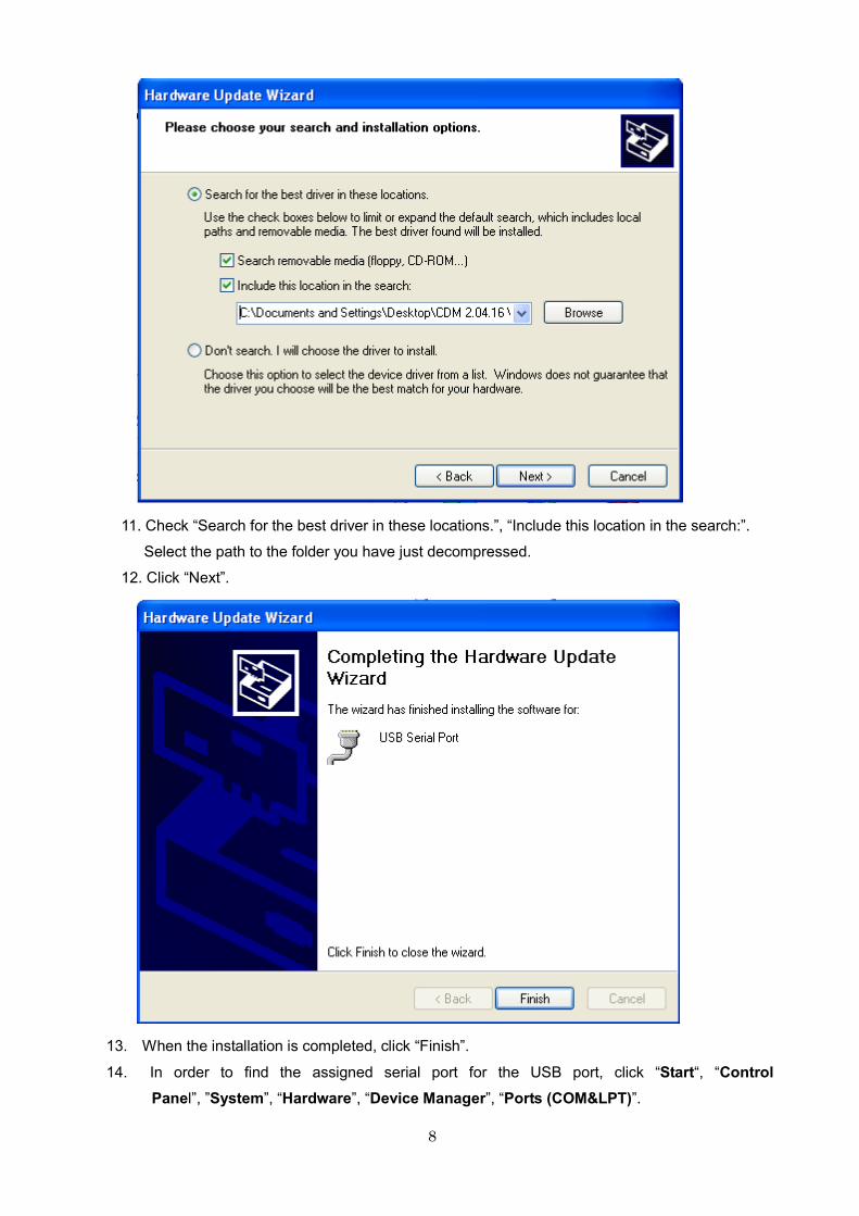
11. Check “Search for the best driver in these locations.”, “Include this location in the search:”.
Select the path to the folder you have just decompressed.
12. Click “Next”.
13. When the installation is completed, click “Finish”.
14. In order to find the assigned serial port for the USB port, click “Start“, “Control
Panel”, ”System”, “Hardware”, “Device Manager”, “Ports (COM&LPT)”.
9
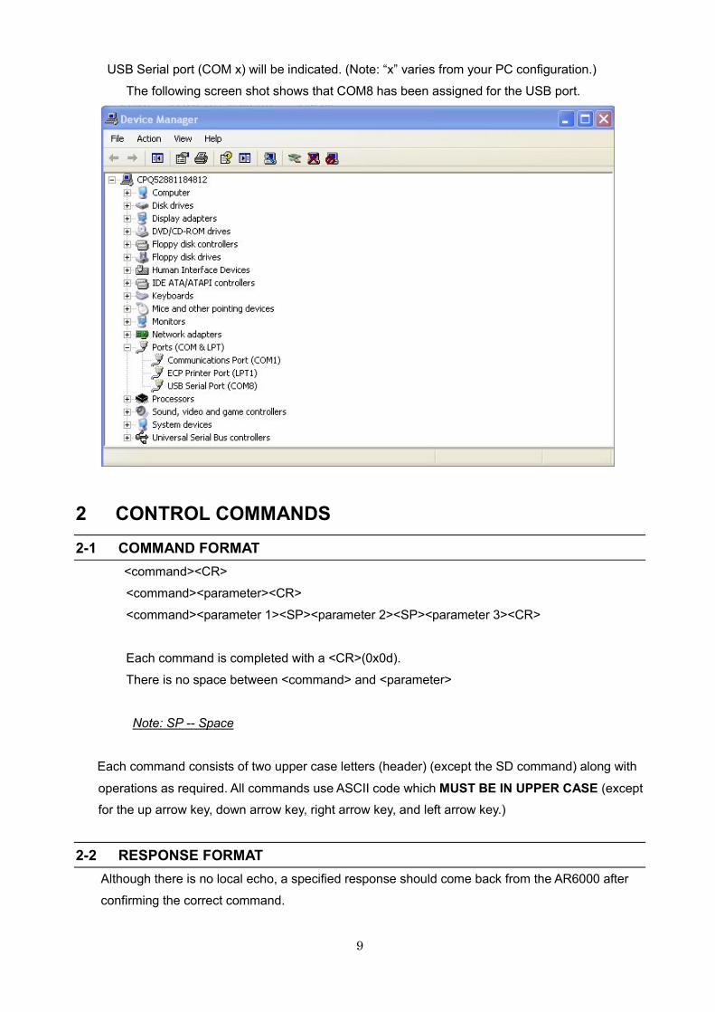
USB Serial port (COM x) will be indicated. (Note: “x” varies from your PC configuration.)
The following screen shot shows that COM8 has been assigned for the USB port.
2 CONTROL COMMANDS
2-1 COMMAND FORMAT
<command><CR>
<command><parameter><CR>
<command><parameter 1><SP><parameter 2><SP><parameter 3><CR>
Each command is completed with a <CR>(0x0d).
There is no space between <command> and <parameter>
Note: SP -- Space
Each command consists of two upper case letters (header) (except the SD command) along with
operations as required. All commands use ASCII code which MUST BE IN UPPER CASE (except
for the up arrow key, down arrow key, right arrow key, and left arrow key.)
2-2 RESPONSE FORMAT
Although there is no local echo, a specified response should come back from the AR6000 after
confirming the correct command.
10
If an invalid command is sent to the AR6000, [ ? <CR><LF> (0x3f, 0x0d, 0x0a) ] will be returned
as an unrecognized command.
<SP><CR><LF> (0x20, 0x0d, 0x0a) to a valid command (without parameter).
<command><value><SP><CR><LF> to a valid command (with parameter.)
2-3 POWER ON/OFF THE AR6000
2-3-1 WAKE UP
Any
key
Power on Wake up from stand-by mode (QP command)
Note: The main power switch must be in the ON position.
2-3-2 STANDBY MODE
QP Switches the AR6000
to standby mode
The main power switch must remain in the ON position.
2-3-3 SLEEP TIMER
QT Sleep Timer QTnn:00 ~ 60 (in minute) (1 minute step) (default: 00)
To read: QT<CR> Response: QTnn
TR
Sleep Timer Display
(Displays the
remaining time)
TR0: display off
TR1: display on (default) (Respond by QT parameter)
To read: TR<CR> Response: TRn
2-3-4 END REMOTE CONTROL
EX End remote control
2-4 AUDIO GAIN
VL VLnnn (nnn: 000 ~ 255)
To read: VL<CR>
Response: VLnnn
2-5 STEP FREQUENCY
ST
STnnnnnn (entry in Hz format) (nnnnnn: 0 ~ 999.999 (kHz))
A decimal within “n” means that the value is in kHz. Note that
for frequencies over 3.15GHz, since the frequency resolution
is 2Hz, if you enter an odd value, it will be automatically
changed to the upper even value.
When “0” is entered, it will be recognized as 1000 kHz
(default:100.0kHz)
To read: ST<CR>
Response: STnnnnnn
11
2-6 FREQUENCY/CHANNEL UP/DOWN
^ (1EH)
v (1FH)
Up
Down
Frequency / memory channel up
Frequency / memory channel down
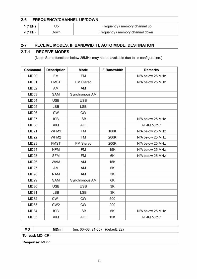
2-7 RECEIVE MODES, IF BANDWIDTH, AUTO MODE, DESTINATION
2-7-1 RECEIVE MODES
(Note: Some functions below 25MHz may not be available due to its configuration.)
Command Description Mode IF Bandwidth Remarks
MD00 FM FM N/A below 25 MHz
MD01 FMST FM Stereo N/A below 25 MHz
MD02 AM AM
MD03 SAM Synchronous AM
MD04 USB USB
MD05 LSB LSB
MD06 CW CW
MD07 ISB ISB N/A below 25 MHz
MD08 AIQ AIQ AF-IQ output
MD21 WFM1 FM 100K N/A below 25 MHz
MD22 WFM2 FM 200K N/A below 25 MHz
MD23 FMST FM Stereo 200K N/A below 25 MHz
MD24 NFM FM 15K N/A below 25 MHz
MD25 SFM FM 6K N/A below 25 MHz
MD26 WAM AM 15K
MD27 AM AM 6K
MD28 NAM AM 3K
MD29 SAM Synchronous AM 6K
MD30 USB USB 3K
MD31 LSB LSB 3K
MD32 CW1 CW 500
MD33 CW2 CW 200
MD34 ISB ISB 6K N/A below 25 MHz
MD35 AIQ AIQ 15K AF-IQ output
MD MDnn (nn: 00~08, 21-35) (default: 22)
To read: MD<CR>
Response: MDnn
12
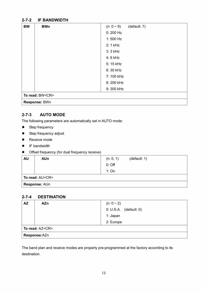
2-7-2 IF BANDWIDTH
BW
BWn
(n: 0 ~ 9) (default: 7)
0: 200 Hz
1: 500 Hz
2: 1 kHz
3: 3 kHz
4: 6 kHz
5: 15 kHz
6: 30 kHz
7: 100 kHz
8: 200 kHz
9: 300 kHz
To read: BW<CR>
Response: BWn
2-7-3 AUTO MODE
The following parameters are automatically set in AUTO mode:
� Step frequency
� Step frequency adjust
� Receive mode
� IF bandwidth
� Offset frequency (for dual frequency receive)
AU
AUn
(n: 0, 1) (default: 1)
0: Off
1: On
To read: AU<CR>
Response: AUn
2-7-4 DESTINATION
AZ
AZn
(n: 0 ~ 2)
0: U.S.A. (default: 0)
1: Japan
2: Europe
To read: AZ<CR>
Response:AZn
The band plan and receive modes are properly pre-programmed at the factory according to its
destination.
13
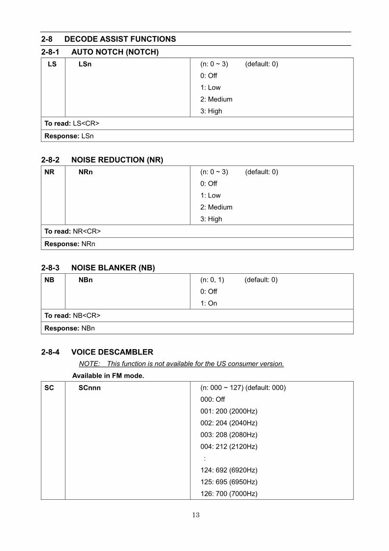
2-8 DECODE ASSIST FUNCTIONS
2-8-1 AUTO NOTCH (NOTCH)
LS
LSn
(n: 0 ~ 3) (default: 0)
0: Off
1: Low
2: Medium
3: High
To read: LS<CR>
Response: LSn
2-8-2 NOISE REDUCTION (NR)
NR
NRn
(n: 0 ~ 3) (default: 0)
0: Off
1: Low
2: Medium
3: High
To read: NR<CR>
Response: NRn
2-8-3 NOISE BLANKER (NB)
NB
NBn
(n: 0, 1) (default: 0)
0: Off
1: On
To read: NB<CR>
Response: NBn
2-8-4 VOICE DESCAMBLER
NOTE: This function is not available for the US consumer version.
Available in FM mode.
SC
SCnnn
(n: 000 ~ 127) (default: 000)
000: Off
001: 200 (2000Hz)
002: 204 (2040Hz)
003: 208 (2080Hz)
004: 212 (2120Hz)
:
124: 692 (6920Hz)
125: 695 (6950Hz)
126: 700 (7000Hz)
14
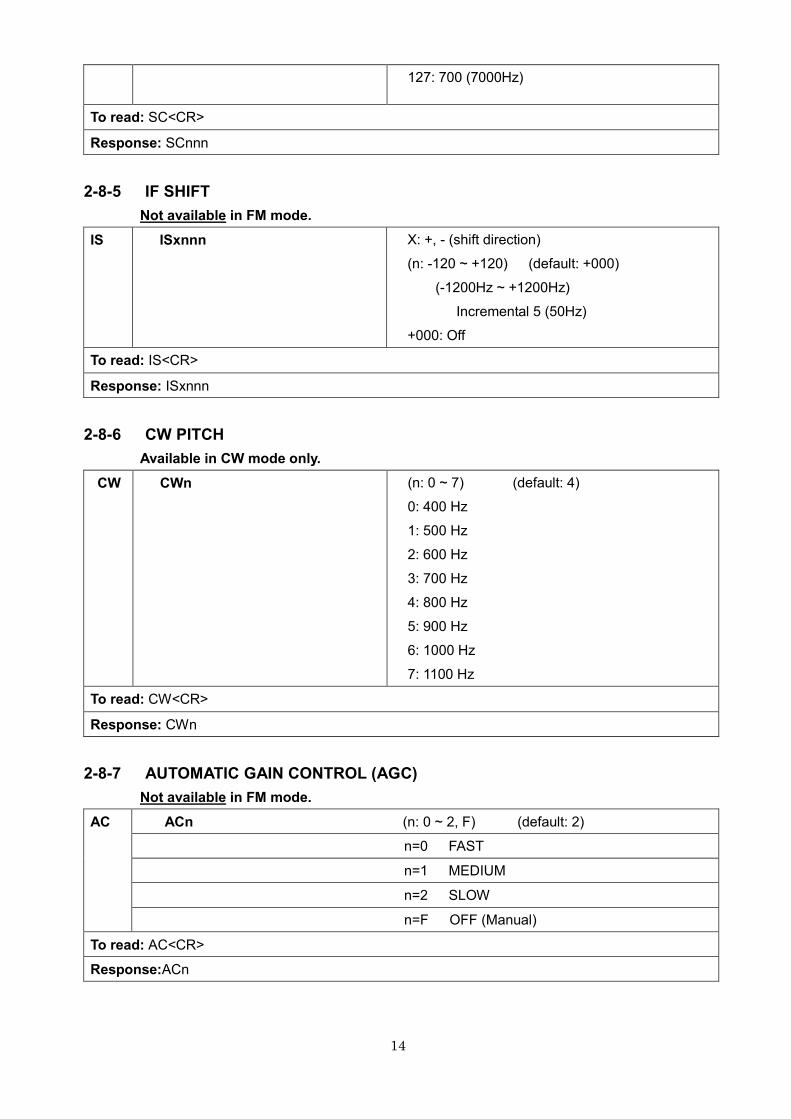
127: 700 (7000Hz)
To read: SC<CR>
Response: SCnnn
2-8-5 IF SHIFT
Not available in FM mode.
IS
ISxnnn
X: +, - (shift direction)
(n: -120 ~ +120) (default: +000)
(-1200Hz ~ +1200Hz)
Incremental 5 (50Hz)
+000: Off
To read: IS<CR>
Response: ISxnnn
2-8-6 CW PITCH
Available in CW mode only.
CW
CWn
(n: 0 ~ 7) (default: 4)
0: 400 Hz
1: 500 Hz
2: 600 Hz
3: 700 Hz
4: 800 Hz
5: 900 Hz
6: 1000 Hz
7: 1100 Hz
To read: CW<CR>
Response: CWn
2-8-7 AUTOMATIC GAIN CONTROL (AGC)
Not available in FM mode.
AC
ACn (n: 0 ~ 2, F) (default: 2)
n=0 FAST
n=1 MEDIUM
n=2 SLOW
n=F OFF (Manual)
To read: AC<CR>
Response:ACn
15
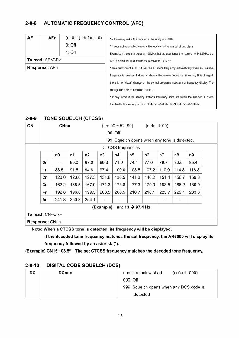
2-8-8 AUTOMATIC FREQUENCY CONTROL (AFC)
AF
AFn
(n: 0, 1) (default: 0)
0: Off
1: On
To read: AF<CR>
Response: AFn
2-8-9 TONE SQUELCH (CTCSS)
CN CNnn (nn: 00 ~ 52, 99) (default: 00)
00: Off
99: Squelch opens when any tone is detected.
CTCSS frequencies
n0 n1 n2 n3 n4 n5 n6 n7 n8 n9
0n - 60.0 67.0 69.3 71.9 74.4 77.0 79.7 82.5 85.4
1n 88.5 91.5 94.8 97.4 100.0 103.5 107.2 110.9 114.8 118.8
2n 120.0 123.0 127.3 131.8 136.5 141.3 146.2 151.4 156.7 159.8
3n 162.2 165.5 167.9 171.3 173.8 177.3 179.9 183.5 186.2 189.9
4n 192.8 196.6 199.5 203.5 206.5 210.7 218.1 225.7 229.1 233.6
5n 241.8 250.3 254.1 - - - - - - -
(Example) nn: 13 ���� 97.4 Hz
To read: CN<CR>
Response: CNnn
Note: When a CTCSS tone is detected, its frequency will be displayed.
If the decoded tone frequency matches the set frequency, the AR6000 will display its
frequency followed by an asterisk (*).
(Example) CN15 103.5* The set CTCSS frequency matches the decoded tone frequency.
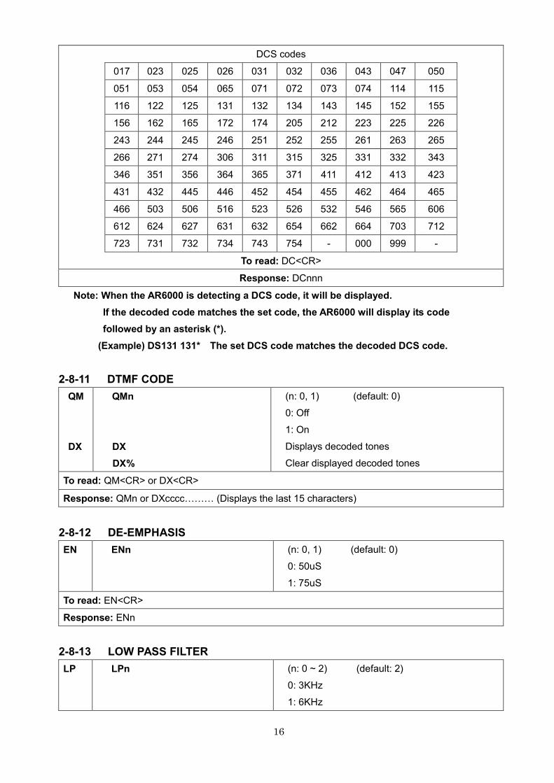
2-8-10 DIGITAL CODE SQUELCH (DCS)
DC
DCnnn
nnn: see below chart (default: 000)
000: Off
999: Squelch opens when any DCS code is
detected
* AFC does only work in NFM mode with a filter setting up to 30kHz.
* It does not automatically retune the receiver to the nearest strong signal.
Example: If there is a signal at 150MHz, but the user tunes the receiver to 149.5MHz, the
AFC function will NOT retune the receiver to 150MHz!
* Real function of AFC: It tunes the IF filter's frequency automatically when an unstable
frequency is received. It does not change the receive frequency. Since only IF is changed,
there is no "visual" change on the control program's spectrum or frequency display. The
change can only be heard on "audio".
* It only works if the sending station's frequency shifts are within the selected IF filter's
bandwidth. For example: IF=15kHz >> +/-7kHz, IF=30kHz >> +/-15kHz
16
DCS codes
017 023 025 026 031 032 036 043 047 050
051 053 054 065 071 072 073 074 114 115
116 122 125 131 132 134 143 145 152 155
156 162 165 172 174 205 212 223 225 226
243 244 245 246 251 252 255 261 263 265
266 271 274 306 311 315 325 331 332 343
346 351 356 364 365 371 411 412 413 423
431 432 445 446 452 454 455 462 464 465
466 503 506 516 523 526 532 546 565 606
612 624 627 631 632 654 662 664 703 712
723 731 732 734 743 754 - 000 999 -
To read: DC<CR>
Response: DCnnn
Note: When the AR6000 is detecting a DCS code, it will be displayed.
If the decoded code matches the set code, the AR6000 will display its code
followed by an asterisk (*).
(Example) DS131 131* The set DCS code matches the decoded DCS code.
2-8-11 DTMF CODE
QM
DX
QMn
DX
DX%
(n: 0, 1) (default: 0)
0: Off
1: On
Displays decoded tones
Clear displayed decoded tones
To read: QM<CR> or DX<CR>
Response: QMn or DXccccVVV (Displays the last 15 characters)
2-8-12 DE-EMPHASIS
EN ENn (n: 0, 1) (default: 0)
0: 50uS
1: 75uS
To read: EN<CR>
Response: ENn
2-8-13 LOW PASS FILTER
LP LPn (n: 0 ~ 2) (default: 2)
0: 3KHz
1: 6KHz
17
2: Thru
To read: LP<CR>
Response: LPn
2-8-14 HIGH PASS FILTER
HP HPn (n: 0 ~ 2) (default: 0)
0: Thru
1: 300Hz
2: 600Hz
To read: LP<CR>
Response: LPn
2-9 SQUELCH
2-9-1 LEVEL SQUELCH (RQ COMMAND)
The RQ command is used to automatically set squelch level according to the receive frequency.
(i.e. if the receive frequency is below 25 MHz, then squelch will be set to HF band.)
RQ
RQnnn
RQnnn.n
(nnn: 000 ~ 255)
(nnn.n: 0.0 ~ 140.0 (dB))
To read: RQ<CR> or RQ.<CR>
Response: RQannn (a: + or <SP>)
+: Squelch opens at the set level
<SP>: Squelch closes at the set level
RQannn.n (a: + or <SP>)
+: Squelch opens at the set level
<SP>: Squelch closes at the set level
Unit: dB
2-9-2 LEVEL SQUELCH (HQ COMMAND)
The HQ command is used to set squelch level for HF band and V/UHF band simultaneously.
HQ
HQuuu<SP>hhh
or
HQuuu.u <SP>hhh.h
uuu: UHF squelch level (uuu: 000 ~ 255)
hhh: HF squelch level (hhh: 000 ~ 255)
uuu.u: 000.0 ~ 140.0 (dB)
hhh.h: 000.0 ~ 140.0 (dB)
To read: HQ<CR> or HQ.<CR>
Response: HQ � HQuuu<SP>hhh
HQ. � HQuuu.u<SP>hhh.h (dB)
18
2-9-3 VOICE SQUELCH
VQ
VT
VV
VQn
VTnnn
VVn
(n: 0, 1) 0: Off, 1: On (default: 0)
nnn:000 ~ 255 Delay time (default: 008)
nn: 0 ~ 7 Squelch level (default: 3)
To read: VQ<CR> or VT<CR> or VL<CR>
Response: VQn or VTnnn or VVn
2-9-4 NOISE SQUELCH (NQ COMMAND)
The NQ command is used to automatically set the squelch level according to the receive frequency.
(i.e. if the receive frequency is below 25 MHz, then squelch will be set to HF band.)
NQ NQnnn (nnn: 000 ~ 255) (default: 016)
To read: NQ<CR>
Response: NQannn (a: + or <SP>)
+: Squelch opens at the set level
<SP>: Squelch closes at the set level
2-9-5 NOISE SQUELCH (QN COMMAND)
The QN command is used to simultaneously set the squelch level for HF band and V/UHF band.
QN QNuuu<SP>hhh uuu: UHF squelch level (uuu: 000 ~ 255) (default: 016)
hhh: HF squelch level (hhh: 000 ~ 255) (default: 018)
To read: QN<CR>
Response: QNuuu<SP>hhh
2-9-6 NOISE SQUELCH ON/OFF
NE NEn (n: 0, 1) (default: 0)
0: Off
1: On
To read: NE<CR>
Response: NEn
2-10 RF AMPLIFIER, ATTENUATOR
AT
ATn n: 0 ~ 4 (default: 0)
n=0 RF AMP = On, Attenuator = 0 dB, Auto attenuator = Off
n=1 RF AMP = Off, Attenuator = 0 dB, Auto attenuator = Off
n=2 RF AMP = Off, Attenuator = -10 dB, Auto attenuator = Off
n=3 RF AMP = Off, Attenuator = -20 dB, Auto attenuator = Off
n=4 Auto attenuator = On
To read: AT<CR>
19
Response: ATyn y : 0, 1 0: Auto attenuator Off
1: Auto attenuator On
n : 0 ~ 3 See above
2-11 ANTENNA SELECT
AN
ANn (n: 0 ~ 4) (default: 1)
n=0 Auto select as programmed by user
n=1 Antenna 1, n=2 Antenna 2
n=3 Antenna 3, n=4 Antenna 4
To read: AN<CR>
Response: ANmn m : 0 ~ 4 Antenna selection by user
n : 1 ~ 4 Antenna number actually active
Note: ANT 1 range: 25MHz - 6GHz, ANT 2 range: 9kHz – 3.15GHz. In other words when the
receive frequency is below 25 MHz, antenna connector 2 is automatically selected and
over 3.15GHz, ANT 1 is automatically selected.
2-12 ANTENNA SELECT PROGRAMMING
Up to four receive frequency ranges can be programmed and assigned to the antenna
input. If left as is, antenna 1 is automatically selected.
2-12-1 PROGRAMMING
AP APa<SP>nnnnnnnnnn<SP>mmmmmmmmmm
a: 1 ~ 4 (antenna connector)
nnnnnnnnnn low end frequency (Hz)
mmmmmmmmmm high end frequency (Hz)
Note: To enter frequencies in MHz, use a . (decimal) in the parameters.
For frequencies below 25 MHz, always use antenna 2 and over 3.15 GHz, always use
antenna 1.
To read: AP<CR> or AP%<CR>
Response: APa<SP>nnnnnnnnnn<SP>mmmmmmmmmm
After responding, APa<SP>- - - <SP> will be displayed.
AP% � Displays all antenna program for antenna 1 ~ 4.
There are up to 10 different programing patterns possible.
2-12-2 DELETING PROGRAM
AD ADan Deletes one frequency data for the specified antenna.
ADa% Deletes all frequency data for the specified antenna.
AD%% Deletes all frequency data for all antennas.
20
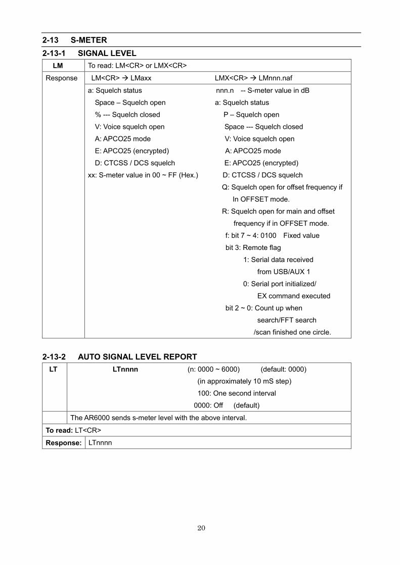
2-13 S-METER
2-13-1 SIGNAL LEVEL
LM To read: LM<CR> or LMX<CR>
Response
LM<CR> � LMaxx LMX<CR> � LMnnn.naf
a: Squelch status nnn.n -- S-meter value in dB
Space – Squelch open a: Squelch status
% --- Squelch closed P – Squelch open
V: Voice squelch open Space --- Squelch closed
A: APCO25 mode V: Voice squelch open
E: APCO25 (encrypted) A: APCO25 mode
D: CTCSS / DCS squelch E: APCO25 (encrypted)
xx: S-meter value in 00 ~ FF (Hex.) D: CTCSS / DCS squelch
Q: Squelch open for offset frequency if
In OFFSET mode.
R: Squelch open for main and offset
frequency if in OFFSET mode.
f: bit 7 ~ 4: 0100 Fixed value
bit 3: Remote flag
1: Serial data received
from USB/AUX 1
0: Serial port initialized/
EX command executed
bit 2 ~ 0: Count up when
search/FFT search
/scan finished one circle.
2-13-2 AUTO SIGNAL LEVEL REPORT
LT LTnnnn (n: 0000 ~ 6000) (default: 0000)
(in approximately 10 mS step)
100: One second interval
0000: Off (default)
The AR6000 sends s-meter level with the above interval.
To read: LT<CR>
Response: LTnnnn

21
2-14 AUDIO RECORDER CONTROL
2-14-1 CONTROL RELAY STATUS
TP TPn (n: 0 , 1)
(READ-ONLY, USER SELECTION NOT POSSIBLE)
0: Off (Relay contact open) (default)
1: On (relay contact closed)
The relay contact is available at the ACC1 connector to control an external audio recorder
device.
When the squelch opens, the relay contact will close.
When squelch closed, then the relay contact will open.
To read: TP<CR>
Response: TPn
2-14-2 CONTROL RELAY STATUS REPORT
TC TCn (n: 0, 1) (default: 0)
0: Off (No report)
1: On (Report by the TP command)
When the control relay opens or closes during receive, the relay operation status will be
output by the TP command if the TC command is set to on.
No report will be made if the TC command is set to 0.
To read: TC<CR>
Response: TCn
2-15 MANUAL RF GAIN
This command is available only when the AGC is set to manual mode.
RG
RGnnn (nnn: 000 ~ 110) (in dB) (default: 110)
To read: RG<CR>
Response: RGnnn
2-16 RF BANDPASS FILTER (FOR BELOW 25 MHz)
HN HNn (n: 0, 1) (default: 0)
0: Off (No filter)
1: On (Filtered)
This command is to install the Band Pass Filter (BPF) under 25 MHz.
To read: HN<CR>
Response: HNn
22
3 RECEIVE COMMANDS
3-1 VFO MODE
Vx
RF
Vx (x: A ~ E)
RFnnnnnnnnnn nnnnnnnnnn (Hz) (default:0088.000000) (MHz)
The Vx command is to select VFO A ~ VFO E.
To set the frequency, use the RF command after selecting the VFO.
To set the frequency in MHz, use a (.) (decimal).
To read: RF<CR>
Response: VXnnnnnnnnnn
3-2 RECEIVE MODE STATUS
RX RX (default: VA RF0088000000 ST100000 AU MD22)
To read: RX<CR>
Response: In VFO mode:
Vx<SP>RFnnnnnnnnnn<SP>STnnnnnna<SP>AUn<SP>MDnn
In memory read mode:
MR<SP>MXnnnn<SP>MPn<>GAn<>RFnnnnnnnnnn<SP>STnnnnnna
<SP> AUn<SP>MDnn<SP>TMcccccccccccc
In scan mode:
MS<SP>MXnnnn<SP>MPn<SP>GAn<SP>RFnnnnnnnnnn<SP>
STnnnnnna<SP>AUn<SP>MDnn<SP>TMcccccccccccc
In select scan mode:
SM<SP>MXnnnn<SP>MPn<SP>GAn<SP>RFnnnnnnnnnn<SP>STnnnnnna
<SP>AUn<SP>MDnn<SP>TMcccccccccccc
In search mode:
SRnn<SP>RFnnnnnnnnnn<SP>STnnnnnna<SP>AUn<SP>MDnn<SP>
TTcccccccccccc
In VFO search mode:
VS<SP>Vx<SP>RFnnnnnnnnnn<SP>STnnnnnna<SP>AUn<SP>MDnn
In FFT search mode:
FFnn<SP>FSnn<SP>FT-nnn<SP>RFnnnnnnnnnn
3-2-1 RECEIVE STATUS AUTO REPORT
RT RTnnnn (nn: 0000 ~ 6000) (in 10 mS) (default: 0000)
100 : 1 second
0000: Off
To read: RT<CR
Response: RTnnnn
23
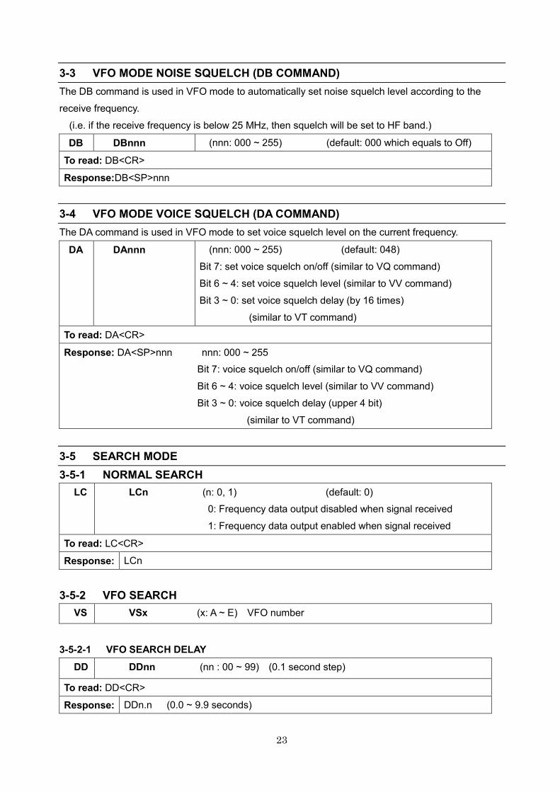
3-3 VFO MODE NOISE SQUELCH (DB COMMAND)
The DB command is used in VFO mode to automatically set noise squelch level according to the
receive frequency.
(i.e. if the receive frequency is below 25 MHz, then squelch will be set to HF band.)
DB DBnnn (nnn: 000 ~ 255) (default: 000 which equals to Off)
To read: DB<CR>
Response:DB<SP>nnn
3-4 VFO MODE VOICE SQUELCH (DA COMMAND)
The DA command is used in VFO mode to set voice squelch level on the current frequency.
DA
DAnnn
(nnn: 000 ~ 255) (default: 048)
Bit 7: set voice squelch on/off (similar to VQ command)
Bit 6 ~ 4: set voice squelch level (similar to VV command)
Bit 3 ~ 0: set voice squelch delay (by 16 times)
(similar to VT command)
To read: DA<CR>
Response: DA<SP>nnn nnn: 000 ~ 255
Bit 7: voice squelch on/off (similar to VQ command)
Bit 6 ~ 4: voice squelch level (similar to VV command)
Bit 3 ~ 0: voice squelch delay (upper 4 bit)
(similar to VT command)
3-5 SEARCH MODE
3-5-1 NORMAL SEARCH
LC
LCn (n: 0, 1) (default: 0)
0: Frequency data output disabled when signal received
1: Frequency data output enabled when signal received
To read: LC<CR>
Response: LCn
3-5-2 VFO SEARCH
VS VSx (x: A ~ E) VFO number
3-5-2-1 VFO SEARCH DELAY
DD DDnn (nn : 00 ~ 99) (0.1 second step)
To read: DD<CR>
Response: DDn.n (0.0 ~ 9.9 seconds)
24
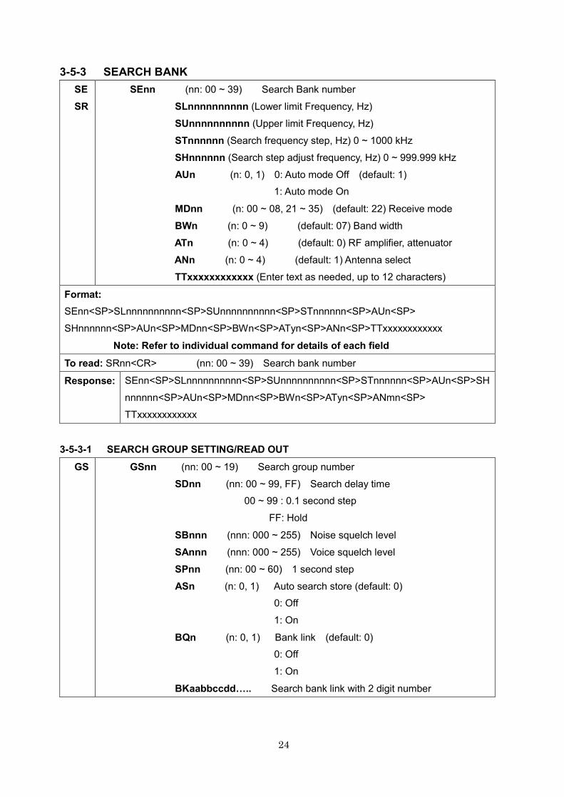
3-5-3 SEARCH BANK
SE
SR
SEnn (nn: 00 ~ 39) Search Bank number
SLnnnnnnnnnn (Lower limit Frequency, Hz)
SUnnnnnnnnnn (Upper limit Frequency, Hz)
STnnnnnn (Search frequency step, Hz) 0 ~ 1000 kHz
SHnnnnnn (Search step adjust frequency, Hz) 0 ~ 999.999 kHz
AUn (n: 0, 1) 0: Auto mode Off (default: 1)
1: Auto mode On
MDnn (n: 00 ~ 08, 21 ~ 35) (default: 22) Receive mode
BWn (n: 0 ~ 9) (default: 07) Band width
ATn (n: 0 ~ 4) (default: 0) RF amplifier, attenuator
ANn (n: 0 ~ 4) (default: 1) Antenna select
TTxxxxxxxxxxxx (Enter text as needed, up to 12 characters)
Format:
SEnn<SP>SLnnnnnnnnnn<SP>SUnnnnnnnnnn<SP>STnnnnnn<SP>AUn<SP>
SHnnnnnn<SP>AUn<SP>MDnn<SP>BWn<SP>ATyn<SP>ANn<SP>TTxxxxxxxxxxxx
Note: Refer to individual command for details of each field
To read: SRnn<CR> (nn: 00 ~ 39) Search bank number
Response: SEnn<SP>SLnnnnnnnnnn<SP>SUnnnnnnnnnn<SP>STnnnnnn<SP>AUn<SP>SH
nnnnnn<SP>AUn<SP>MDnn<SP>BWn<SP>ATyn<SP>ANmn<SP>
TTxxxxxxxxxxxx
3-5-3-1 SEARCH GROUP SETTING/READ OUT
GS
GSnn (nn: 00 ~ 19) Search group number
SDnn (nn: 00 ~ 99, FF) Search delay time
00 ~ 99 : 0.1 second step
FF: Hold
SBnnn (nnn: 000 ~ 255) Noise squelch level
SAnnn (nnn: 000 ~ 255) Voice squelch level
SPnn (nn: 00 ~ 60) 1 second step
ASn (n: 0, 1) Auto search store (default: 0)
0: Off
1: On
BQn (n: 0, 1) Bank link (default: 0)
0: Off
1: On
BKaabbccddL.. Search bank link with 2 digit number
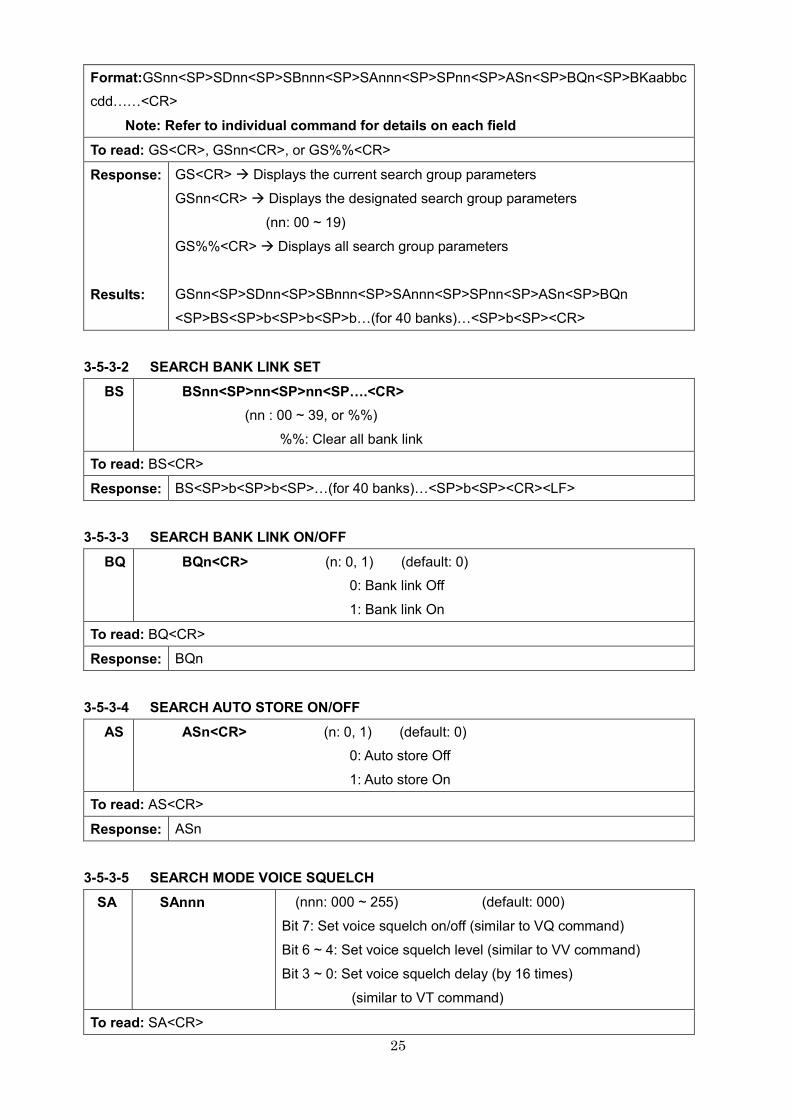
25
Format:GSnn<SP>SDnn<SP>SBnnn<SP>SAnnn<SP>SPnn<SP>ASn<SP>BQn<SP>BKaabbc
cddVV<CR>
Note: Refer to individual command for details on each field
To read: GS<CR>, GSnn<CR>, or GS%%<CR>
Response:
Results:
GS<CR> � Displays the current search group parameters
GSnn<CR> � Displays the designated search group parameters
(nn: 00 ~ 19)
GS%%<CR> � Displays all search group parameters
GSnn<SP>SDnn<SP>SBnnn<SP>SAnnn<SP>SPnn<SP>ASn<SP>BQn
<SP>BS<SP>b<SP>b<SP>bV(for 40 banks)V<SP>b<SP><CR>
3-5-3-2 SEARCH BANK LINK SET
BS BSnn<SP>nn<SP>nn<SPL.<CR>
(nn : 00 ~ 39, or %%)
%%: Clear all bank link
To read: BS<CR>
Response: BS<SP>b<SP>b<SP>V(for 40 banks)V<SP>b<SP><CR><LF>
3-5-3-3 SEARCH BANK LINK ON/OFF
BQ BQn<CR> (n: 0, 1) (default: 0)
0: Bank link Off
1: Bank link On
To read: BQ<CR>
Response: BQn
3-5-3-4 SEARCH AUTO STORE ON/OFF
AS ASn<CR> (n: 0, 1) (default: 0)
0: Auto store Off
1: Auto store On
To read: AS<CR>
Response: ASn
3-5-3-5 SEARCH MODE VOICE SQUELCH
SA
SAnnn
(nnn: 000 ~ 255) (default: 000)
Bit 7: Set voice squelch on/off (similar to VQ command)
Bit 6 ~ 4: Set voice squelch level (similar to VV command)
Bit 3 ~ 0: Set voice squelch delay (by 16 times)
(similar to VT command)
To read: SA<CR>
26
Response: SA<SP>nnn nnn: 000 ~ 255
Bit 7: Voice squelch on/off (similar to VQ command)
Bit 6 ~ 4: Voice squelch level (similar to VV command)
Bit 3 ~ 0: Voice squelch delay (upper 4 bit)
(similar to VT command)
3-5-3-6 SEARCH MODE NOISE SQUELCH
SB
SBnnn
(nnn: 000 ~ 255)
000: Off (default: 000)
To read: SB<CR>
Response: SB<SP>nnn
3-5-3-7 SEARCH MODE DELAY TIME
SD
SDnn
(nn: 00 ~ 99, FF) 0.1 second step
FF: Hold (default: 20 = 2 seconds)
To read: SD<CR>
Response: SDn.n (n.n : 0.0 ~ 9.9) or SDFF
3-5-3-8 SEARCH MODE PAUSE TIME
SP
SPnn
(nn: 00 ~ 60) 1 second step
(default: 00)
To read: SP<CR>
Response: SP<SP>nn
3-5-3-9 SEARCH BANK DELETE
QS QS Delete current search bank
QSnn Delete specified search bank (nn : 00 ~ 39)
Search bank number
3-5-4 PASS FREQUENCY
PW
1. PW � In VFO search mode or search mode, register the current frequency to the
current pass bank while search stops.
2. PWbb ���� In VFO search mode or search mode, register the current frequency to the
specified (bb) pass bank while search stops.
3. PW:mmmmmmmmmm (Hz) � In VFO search mode, search mode, or FFT search
mode, register the specified frequency to the current pass bank.
PW:mmmmmmmmmm (Hz)<SP>nnnnnnnnnn (Hz) � In VFO search mode,
search mode, or FFT search mode, register the specified frequency range
to the current pass bank.
27
4. PWbb<SP>mmmmmmmmmm (Hz) � In VFO search mode, search mode, or FFT
search mode, register the current frequency range to the specified (bb)
pass bank.
PWbb<SP>mmmmmmmmmm (Hz)<SP>nnnnnnnnnn (Hz) � In VFO search
mode, search mode, or FFT search mode, register the specified frequency
range to the specific (bb) pass bank.
5. PW%% ���� In VFO search mode or search mode, register the current frequency
range to all pass banks while search stops.
6. PW%%<SP>mmmmmmmmmm (Hz) � Register the specified frequency to all
pass banks.
PW%%mmmmmmmmm<SP>nnnnnnnnnn (Hz) � Register the specified
frequency range to all pass banks.
After PW command is sent, search function will resume.
PR PRnn Displays pass frequency list
(nn: 00 ~ 40) Pass bank number, 40: for VFO search
PRnn<SP>mm<SP>xxxxxxxxxx
(nn: pass bank number, mm: pass frequency number)
or
PRnn<SP>mm<SP>xxxxxxxxxx<SP>yyyyyyyyyy
(if the pass frequency range is registered.)
PRnn<SP>mm<SP>- - - (End of pass frequency list)
PD PDnnmm (nn: 00 ~ 40) Pass bank number, 40: for VFO search
(mm: Pass frequency number. Input %% for all pass frequencies.
Delete search data and pass frequency on the designated search bank
PD%%%%
Delete all search data and pass frequencies on all search banks
3-5-5 PASS FREQUENCY (PS COMMAND)
PS PSnnnnnnnnnn (Hz) � In VFO search mode, search mode, or FFT search mode,
register the specified frequency to the current search bank.
3-5-6 SEARCH FREQUENCY LIST
FL
There are 1024 channels of search memory in the AR6000. By executing the FL
command, 40 channels of data will be displayed.

28
FLn (n: 0 ~ 4, %)
0: Displays the latest 40 channels (frequencies may duplicate.)
1: Displays the latest 40 channels (frequency not duplicated)
2: Displays 40 channels with the strongest signal
(frequency may be duplicated).
3: Displays 40 channels with the strongest signal
(frequency not duplicated.)
4: Displays most frequently detected signals.
% : Clear search list
3-5-7 COPY SEARCH FREQUENCY LIST TO MEMORY BANK
FM
FMn (n: 0 ~ 4, %)
0: Copy the latest 40 channels to Memory bank #38
(frequencies may duplicate.)
1: Copy the latest 40 channels to Memory bank #38
(frequency not duplicated)
2: Copy 40 channels with the strongest signal to Memory bank #38
(frequency may duplicate)
3: Copy 40 channels with the strongest signal to Memory bank #38
(frequency not duplicated.)
4: Copy most frequently detected signals to Memory bank #38
%: Delete search list
3-5-8 FFT SEARCH
FFT search differs from regular scanning methods (one frequency / step after the other) in that it
provides a spectrum [image] up to 10 MHz wide, sampled 15 times per second.
Although the search bank basic settings for normal search and FFT search are done the same way
(for Low Frequency, High Frequency, and text settings), in FFT search the following parameters must
also be set.
29
FFT frequency step
Threshold level (signal detection level)
FF
LC
FFmm<SP>FSnn<SP>FT-ddd
FFmm Search bank (two digits)
(mm: 00 ~ 39)
FSnn FFT search step frequency
(nn: 00 ~ 10)
00: 5 kHz
01: 6.25 kHz
02: 8.333 kHz
03: 9 kHz
04: 10 kHz
05: 12.5 kHz
06: 20 kHz (default)
07: 25 kHz
08: 30 kHz
09: 50 kHz
10: 100 kHz
FT-ddd Threshold level.
Once set, only signals over this level will be detected by
FFT search.
-ddd: (0 ~ 110 dB) (default: -80) (dB)
LCn n: 0, 1
0: Disable search result frequency report
1: Enable search result frequency report
(Note: The FS, FT commands cannot be used alone.
They must always be used in conjunction with the FF command.)
3-6 MEMORY CHANNEL
The AR6000 features 2,000 memory channels (50 channels in each of the 40 banks).
The number of memory banks can be reconfigured between 5 ~ 95 (in 5 incremental).
3-6-1 MEMORY READ MODE
MR MRmmnn mm: 00 ~ 39 (Memory bank) (default: 00)
nn: 00 ~ 99 (Memory channel) (default: 00)
To read: MRmmnn<CR>
30
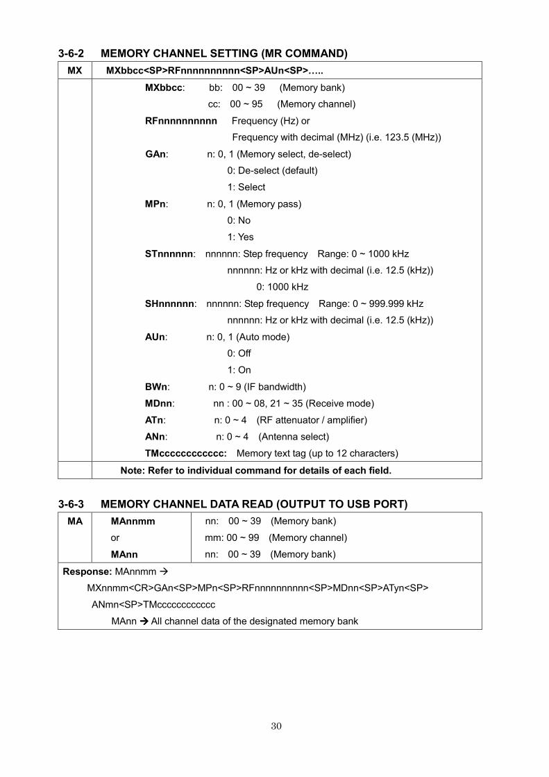
3-6-2 MEMORY CHANNEL SETTING (MR COMMAND)
MX MXbbcc<SP>RFnnnnnnnnnn<SP>AUn<SP>L..
MXbbcc: bb: 00 ~ 39 (Memory bank)
cc: 00 ~ 95 (Memory channel)
RFnnnnnnnnnn Frequency (Hz) or
Frequency with decimal (MHz) (i.e. 123.5 (MHz))
GAn: n: 0, 1 (Memory select, de-select)
0: De-select (default)
1: Select
MPn: n: 0, 1 (Memory pass)
0: No
1: Yes
STnnnnnn: nnnnnn: Step frequency Range: 0 ~ 1000 kHz
nnnnnn: Hz or kHz with decimal (i.e. 12.5 (kHz))
0: 1000 kHz
SHnnnnnn: nnnnnn: Step frequency Range: 0 ~ 999.999 kHz
nnnnnn: Hz or kHz with decimal (i.e. 12.5 (kHz))
AUn: n: 0, 1 (Auto mode)
0: Off
1: On
BWn: n: 0 ~ 9 (IF bandwidth)
MDnn: nn : 00 ~ 08, 21 ~ 35 (Receive mode)
ATn: n: 0 ~ 4 (RF attenuator / amplifier)
ANn: n: 0 ~ 4 (Antenna select)
TMcccccccccccc: Memory text tag (up to 12 characters)
Note: Refer to individual command for details of each field.
3-6-3 MEMORY CHANNEL DATA READ (OUTPUT TO USB PORT)
MA
MAnnmm
or
MAnn
nn: 00 ~ 39 (Memory bank)
mm: 00 ~ 99 (Memory channel)
nn: 00 ~ 39 (Memory bank)
Response: MAnnmm �
MXnnmm<CR>GAn<SP>MPn<SP>RFnnnnnnnnnn<SP>MDnn<SP>ATyn<SP>
ANmn<SP>TMcccccccccccc
MAnn ���� All channel data of the designated memory bank
31
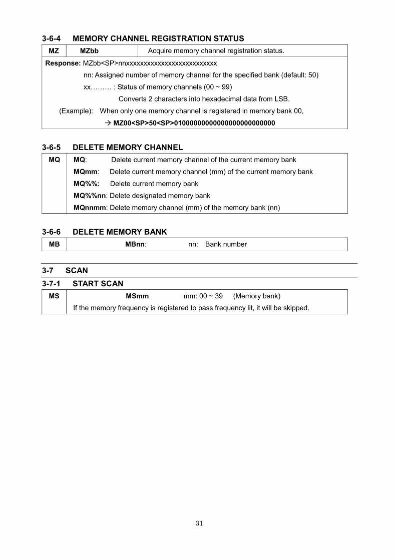
3-6-4 MEMORY CHANNEL REGISTRATION STATUS
MZ MZbb Acquire memory channel registration status.
Response: MZbb<SP>nnxxxxxxxxxxxxxxxxxxxxxxxxxx
nn: Assigned number of memory channel for the specified bank (default: 50)
xxVVV : Status of memory channels (00 ~ 99)
Converts 2 characters into hexadecimal data from LSB.
(Example): When only one memory channel is registered in memory bank 00,
� MZ00<SP>50<SP>01000000000000000000000000
3-6-5 DELETE MEMORY CHANNEL
MQ MQ: Delete current memory channel of the current memory bank
MQmm: Delete current memory channel (mm) of the current memory bank
MQ%%: Delete current memory bank
MQ%%nn: Delete designated memory bank
MQnnmm: Delete memory channel (mm) of the memory bank (nn)
3-6-6 DELETE MEMORY BANK
MB MBnn: nn: Bank number
3-7 SCAN
3-7-1 START SCAN
MS MSmm mm: 00 ~ 39 (Memory bank)
If the memory frequency is registered to pass frequency lit, it will be skipped.
32
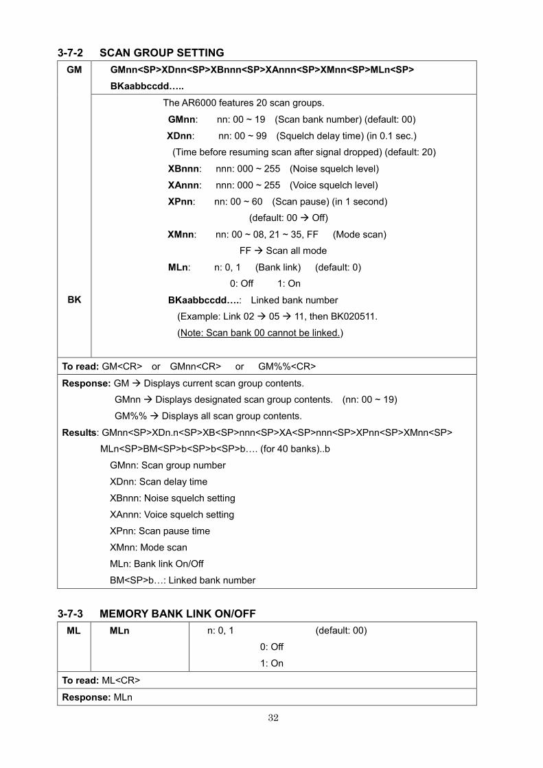
3-7-2 SCAN GROUP SETTING
GM
BK
GMnn<SP>XDnn<SP>XBnnn<SP>XAnnn<SP>XMnn<SP>MLn<SP>
BKaabbccddL..
The AR6000 features 20 scan groups.
GMnn: nn: 00 ~ 19 (Scan bank number) (default: 00)
XDnn: nn: 00 ~ 99 (Squelch delay time) (in 0.1 sec.)
(Time before resuming scan after signal dropped) (default: 20)
XBnnn: nnn: 000 ~ 255 (Noise squelch level)
XAnnn: nnn: 000 ~ 255 (Voice squelch level)
XPnn: nn: 00 ~ 60 (Scan pause) (in 1 second)
(default: 00 � Off)
XMnn: nn: 00 ~ 08, 21 ~ 35, FF (Mode scan)
FF � Scan all mode
MLn: n: 0, 1 (Bank link) (default: 0)
0: Off 1: On
BKaabbccddL.: Linked bank number
(Example: Link 02 � 05 � 11, then BK020511.
(Note: Scan bank 00 cannot be linked.)
To read: GM<CR> or GMnn<CR> or GM%%<CR>
Response: GM � Displays current scan group contents.
GMnn � Displays designated scan group contents. (nn: 00 ~ 19)
GM%% � Displays all scan group contents.
Results: GMnn<SP>XDn.n<SP>XB<SP>nnn<SP>XA<SP>nnn<SP>XPnn<SP>XMnn<SP>
MLn<SP>BM<SP>b<SP>b<SP>bV. (for 40 banks)..b
GMnn: Scan group number
XDnn: Scan delay time
XBnnn: Noise squelch setting
XAnnn: Voice squelch setting
XPnn: Scan pause time
XMnn: Mode scan
MLn: Bank link On/Off
BM<SP>bV: Linked bank number
3-7-3 MEMORY BANK LINK ON/OFF
ML
MLn
n: 0, 1 (default: 00)
0: Off
1: On
To read: ML<CR>
Response: MLn
33
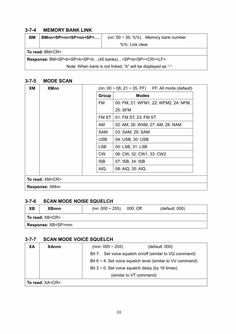
3-7-4 MEMORY BANK LINK
BM
BMnn<SP>nn<SP>nn<SP>L. (nn: 00 ~ 39, %%) Memory bank number
%%: Link clear
To read: BM<CR>
Response: BM<SP>b<SP>b<SP>bV(40 banks)V<SP>b<SP><CR><LF>
Note: When bank is not linked, “b” will be displayed as “-“.
3-7-5 MODE SCAN
XM XMnn (nn: 00 ~ 08, 21 ~ 35, FF) FF: All mode (default)
Group Modes
FM 00: FM, 21: WFM1, 22: WFM2, 24: NFM,
25: SFM
FM ST 01: FM ST, 23: FM ST
AM 02: AM, 26: WAM, 27: AM, 28: NAM
SAM 03: SAM, 29: SAM
USB 04: USB, 30: USB
LSB 05: LSB, 31: LSB
CW 06: CW, 32: CW1, 33: CW2
ISB 07: ISB, 34: ISB
AIQ 08: AIQ, 35: AIQ
To read: XM<CR>
Response: XMnn
3-7-6 SCAN MODE NOISE SQUELCH
XB XBnnn (nn: 000 ~ 255) 000: Off (default: 000)
To read: XB<CR>
Response: XB<SP>nnn
3-7-7 SCAN MODE VOICE SQUELCH
XA
XAnnn
(nnn: 000 ~ 255) (default: 000)
Bit 7: Set voice squelch on/off (similar to VQ command)
Bit 6 ~ 4: Set voice squelch level (similar to VV command)
Bit 3 ~ 0: Set voice squelch delay (by 16 times)
(similar to VT command)
To read: XA<CR>
34
Response: XA<SP>nnn nnn: 000 ~ 255
Bit 7: Voice squelch on/off (similar to VQ command)
Bit 6 ~ 4: Voice squelch level (similar to VV command)
Bit 3 ~ 0: Voice squelch delay (upper 4 bit)
(similar to VT command)
3-7-8 SCAN MODE DELAY TIME
XD
XDnn
(nn: 00 ~ 99) 0.1 second step
(default: 20 = 2 seconds)
To read: XD<CR>
Response: XDn.n (n.n : 0.0 ~ 9.9)
3-7-9 SCAN MODE PAUSE TIME
XP
XPnn
(nn: 00 ~ 60) 1 second step
(default: 00)
To read: XP<CR>
Response: XPnn
3-7-10 MEMORY PASS
MP
MPn
or
MPnn
n: 0, 1 (0: Off and 1: On)
nn: 00 ~ 39, or %% (Memory bank)
%%: Off for all memory banks
To read: MP<CR>
Response: MPn
3-7-11 SELECT SCAN
The select scan function allows you to scan only a selection of the frequencies that were previously
saved as memory channels. A maximum of 100 channels within a bank can be scanned.
3-7-11-1 START SELECT SCAN
SM SM (direct command)
3-7-11-2 SELECT SCAN SETTING
GA
GAn: n: 0, 1, or %%
0: Select scan Off
1: Select scan On
%%: Select Off for all memory banks, channels
To read: GA<CR>
Response: GAn
35
3-7-11-3 SELECT SCAN MEMORY CLEAR
GD GD Clear select scan memory (direct command)
3-7-11-4 READ SELECT MEMORY
GR GR Read select memory (direct command)
To read: GR<CR>
Response: GRnnnn<SP>MXnnmm<SP>RFnnnnnnnnnn<SP>TMcccccccccccc
GR---- at the end of the list
3-8 MULTI FREQUENCY RECEIVE
The Dual frequency / Triple frequency receive functions allow you to monitor two or three separate
frequencies simultaneously.
3-8-1 DUAL FREQUENCY RECEIVE (DUAL BAND RECEIVE MODE)
One frequency below 25 MHz set on the VFO-E (as a sub band) and an another frequency above
25 MHz set on the VFO (other than VFO-E, as a main band) can be received simultaneously.
The received audio for both frequencies are available from the headphone jack independently.
Mixed audio for both signals is available at the external speaker jack.
Below are the conditions for Dual frequency receive function:
(For main band)
� Frequency must be above 25 MHz.
� The FM stereo mode is not available in this mode.
� The receiver must be in VFO mode and it must be set on other than VFO-E.
� The antenna input must use number 1.
(For sub band)
� Frequency must be below 25 MHz.
� The VFO must be set to VFO-E.
3-8-1-1 DUAL FREQUENCY RECEIVE
VW
VWnm: n: A ~ D (VFO), @
@: Duo receive off (default)
m: 0, 1
0: VFO-n (main band) (default)
1: VFO-E (sub band)
To read: VW<CR>
Response: VWnm
36
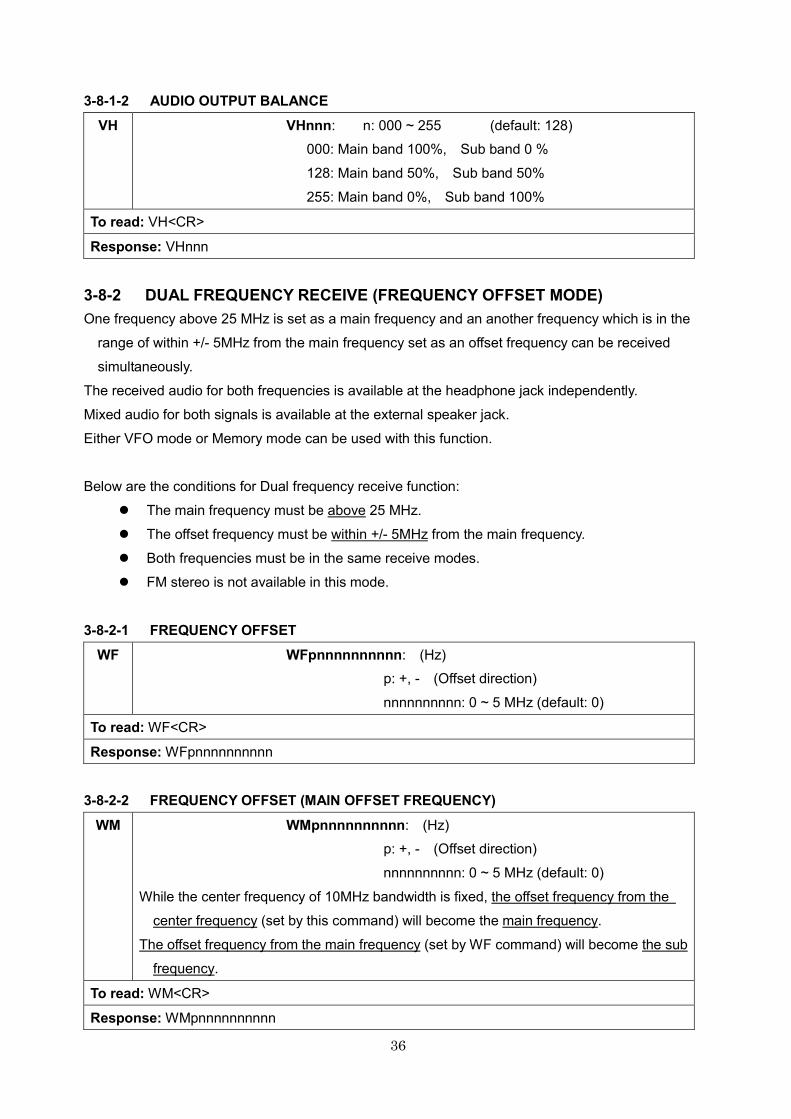
3-8-1-2 AUDIO OUTPUT BALANCE
VH
VHnnn: n: 000 ~ 255 (default: 128)
000: Main band 100%, Sub band 0 %
128: Main band 50%, Sub band 50%
255: Main band 0%, Sub band 100%
To read: VH<CR>
Response: VHnnn
3-8-2 DUAL FREQUENCY RECEIVE (FREQUENCY OFFSET MODE)
One frequency above 25 MHz is set as a main frequency and an another frequency which is in the
range of within +/- 5MHz from the main frequency set as an offset frequency can be received
simultaneously.
The received audio for both frequencies is available at the headphone jack independently.
Mixed audio for both signals is available at the external speaker jack.
Either VFO mode or Memory mode can be used with this function.
Below are the conditions for Dual frequency receive function:
� The main frequency must be above 25 MHz.
� The offset frequency must be within +/- 5MHz from the main frequency.
� Both frequencies must be in the same receive modes.
� FM stereo is not available in this mode.
3-8-2-1 FREQUENCY OFFSET
WF
WFpnnnnnnnnnn: (Hz)
p: +, - (Offset direction)
nnnnnnnnnn: 0 ~ 5 MHz (default: 0)
To read: WF<CR>
Response: WFpnnnnnnnnnn
3-8-2-2 FREQUENCY OFFSET (MAIN OFFSET FREQUENCY)
WM
WMpnnnnnnnnnn: (Hz)
p: +, - (Offset direction)
nnnnnnnnnn: 0 ~ 5 MHz (default: 0)
While the center frequency of 10MHz bandwidth is fixed, the offset frequency from the
center frequency (set by this command) will become the main frequency.
The offset frequency from the main frequency (set by WF command) will become the sub
frequency.
To read: WM<CR>
Response: WMpnnnnnnnnnn
37
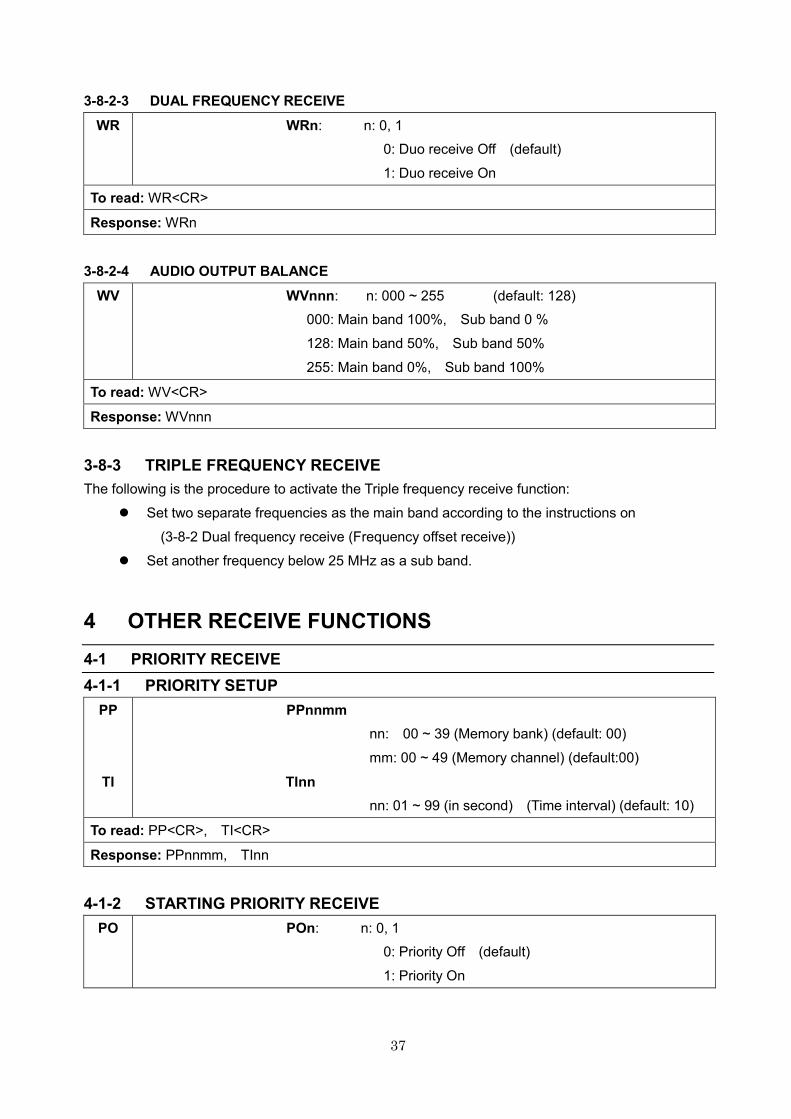
3-8-2-3 DUAL FREQUENCY RECEIVE
WR
WRn: n: 0, 1
0: Duo receive Off (default)
1: Duo receive On
To read: WR<CR>
Response: WRn
3-8-2-4 AUDIO OUTPUT BALANCE
WV
WVnnn: n: 000 ~ 255 (default: 128)
000: Main band 100%, Sub band 0 %
128: Main band 50%, Sub band 50%
255: Main band 0%, Sub band 100%
To read: WV<CR>
Response: WVnnn
3-8-3 TRIPLE FREQUENCY RECEIVE
The following is the procedure to activate the Triple frequency receive function:
� Set two separate frequencies as the main band according to the instructions on
(3-8-2 Dual frequency receive (Frequency offset receive))
� Set another frequency below 25 MHz as a sub band.
4 OTHER RECEIVE FUNCTIONS
4-1 PRIORITY RECEIVE
4-1-1 PRIORITY SETUP
PP
TI
PPnnmm
nn: 00 ~ 39 (Memory bank) (default: 00)
mm: 00 ~ 49 (Memory channel) (default:00)
TInn
nn: 01 ~ 99 (in second) (Time interval) (default: 10)
To read: PP<CR>, TI<CR>
Response: PPnnmm, TInn
4-1-2 STARTING PRIORITY RECEIVE
PO
POn: n: 0, 1
0: Priority Off (default)
1: Priority On
38
To read: PO<CR>
Response: POn
4-2 STEP ADJUST
SH
SHnnnnnn: nnnnnn: (in Hz) Range:0 ~ 999.999 kHz
(default: 000.000)
To read: SH<CR>
Response:SHnnnnnn
4-3 SUB FREQUENCY STEP (FOR SUB DIAL)
SJ
SJx: x: 0 ~ A ( in Hex.) (default: 0)
0: Same with main dial step frequency
1: x 10
2: 100Hz
3: 500Hz
4: 1kHz
5: 5kHz
6: 10kHz
7: 50kHz
8: 100kHz
9: 500kHz
A: 1000kHz (1MHz)
To read: SJ<CR>
Response:SJx
5 SPECTRUM DISPLAY
5-1 START FREQUENCY
TF
TFnnnnnnnnnn: nnnnnnnnnn (Hz)
(default: 83.000) (MHz)
To read: TF<CR>
Response: TFnnnnnnnnnn
5-2 END FREQUENCY
EF
EFnnnnnnnnnn: nnnnnnnnnn (Hz)
(default: 93.000) (MHz)
To read: EF<CR>
Response: EFnnnnnnnnnn
39
5-3 CENTER FREQUENCY
CF
CFnnnnnnnnnn: nnnnnnnnnn (Hz)
(default: 88.000) (MHz)
To read: CF<CR>
Response: CFnnnnnnnnnn
5-4 SPAN FREQUENCY
FP
FPnnnnnnnnnn: nnnnnnnnnn (Hz)
(default: 10.000) (MHz) Selectable from 0.4 to 10MHz.
To read: FP<CR>
Response: FPnnnnnnnnnn
5-5 SPECTRUM STEP FREQUENCY
FE
FEnnnnnn: nnnnnn (Hz)
(default: 62.500) (kHz)
The value is equal to 1/160 of the frequency span.
To read: FE<CR>
Response: FEnnnnnn
5-6 MARKER FREQUENCY
5-6-1 MARKER FREQUENCY
KF
KFnnnnnnnnnn: nnnnnnnmmm (Hz)
(default: 88.000) (MHz)
The entered value may be changed according to the
frequency span and frequency range.
To read: KF<CR>
Response: KFnnnnnnnnnn
5-6-2 MARKER FREQUENCY / LEVEL AUTO OUTPUT
KC
KCn n: 0, 1
0: Disable data output (default)
1: Enable data output
To read: KC<CR>
Response: KCn Data output:MKnnnnnnnnnn –mmm ( -mmm: signal level (in dB))
5-6-3 TRANSFER MARKER FREQUENCY TO RECEIVE FREQUENCY
KG
KG
(Direct command)
40
5-7 SPECTRUM DATA OUTPUT
GL
Output the level data of each frequency on the screen.
GL<SP><CR><LF>/<SP><CR><LF>
(Note: The separator (/<CR><LF>) has 160 lines.
To read: GL<CR>
Response: FnnnnnnnnnnL-ddd (for 1 line of data)
5-8 HIGH SPEED SPECTRUM DATA OUTPUT
FD
Output the level data of each frequency on the screen in high speed.
Convert the signal strength data of one horizontal dot into 1 byte character.
Then repeat this step for a total of 160 characters and output these data followed by
the OK response (<SP><CR><LF>).
To convert the output data to a signal strength level, subtract 0x20 (in hexadecimal), then
add -100dB.
FD<SP><CR><LF>
To read: FD<CR>
Response: FDddddddddV..(160 characters) V ddd
6 VIDEO FUNCTION
6-1 VIDEO FUNCTION
TV
TVn n: 0, 1 (default: 0)
0: Video function off
1: Video function on
(Note: Video output is available only from
the video output connector on the rear panel.)
To read: TV<CR>
Response: TVn
6-2 VIDEO IF REVERSE
VN
Some video transmitters utilize reversed frequency shift modulation in order to
scramble the signal.
VNn n: 0, 1 (default: 0)
0: Normal shift
1: Reverse shift
To read: VN<CR>
Response: VNn
41
7 SD CARD
7-1 SD CARD INFORMATION
SD<SP>INF
SD<SP>INF
Displays the card’s capacity, memory usage.
To read: SD<SP>INF<CR>
Response: SD<SP>INF<SP>Free:nnnnnnnnnnKB(tt.hh)<SP>Total:mmmmmmmmmmKB<SP>
nnnnnnnnnn: Remaining capacity (in KB)
tt.t: Possible recordable time
(Note: Maximum record size is 2GB/file)
mmmmmmmmmm: Total capacity
Error message: SD<SP>INF<SP>CardBusy ---- Busy processing
SD<SP>INF<SP>NoCard --- SD card not detected
SD<SP>INF<SP>FAT12 --- Unusable SD card (FAT12 format)
SD<SP>INF<SP>error ---- Other errors
7-2 FILE DIRECTORY
SD<SP>DIR
SD<SP>DIR
Displays the card’s file directory.
To read: SD<SP>DIR<CR>
Response: Following message will display for each file
WAV file:
SD<SP>DIR<SP>ffffffff.WAV<SP>hh:mm:ss.s<SP>yyyy/mm/dd<SP>hh:mm:ss
Others:
SD<SP>DIR<SP>ffffffff.eee<SP><SP>nnnnnnnnnn<SP><SP>yyyy/mm/dd
<SP>hh:mm:ss
ffffffff.eee: File name, extension
hh:mm:ss.s: Recordable time in WAV file
nnnnnnnnnn: File size (in Byte)
yyyy/mm/dd<SP>hh:mm:ss: File time stamp
At the end of file data: SD<SP>DIR<SP>nnnFile(s)
nnn: Number of files
Error message: SD<SP>DIR<SP>CardBusy ---- Busy processing
SD<SP>DIR<SP>NoCard --- SD card not detected
SD<SP>DIR<SP>FAT12 --- Unusable SD card (FAT12 format)
SD<SP>DIR<SP>error ---- Other errors
42
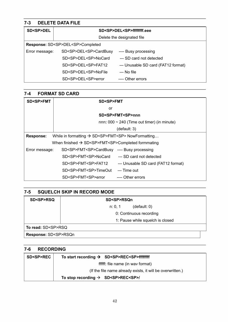
7-3 DELETE DATA FILE
SD<SP>DEL SD<SP>DEL<SP>ffffffff.eee
Delete the designated file
Response: SD<SP>DEL<SP>Completed
Error message: SD<SP>DEL<SP>CardBusy ---- Busy processing
SD<SP>DEL<SP>NoCard --- SD card not detected
SD<SP>DEL<SP>FAT12 --- Unusable SD card (FAT12 format)
SD<SP>DEL<SP>NoFile --- No file
SD<SP>DEL<SP>error ---- Other errors
7-4 FORMAT SD CARD
SD<SP>FMT
SD<SP>FMT
or
SD<SP>FMT<SP>nnn
nnn: 000 ~ 240 (Time out timer) (in minute)
(default: 3)
Response: While in formatting � SD<SP>FMT<SP> NowFormattingV
When finished � SD<SP>FMT<SP>Completed formmating
Error message: SD<SP>FMT<SP>CardBusy ---- Busy processing
SD<SP>FMT<SP>NoCard --- SD card not detected
SD<SP>FMT<SP>FAT12 --- Unusable SD card (FAT12 format)
SD<SP>FMT<SP>TimeOut --- Time out
SD<SP>FMT<SP>error ---- Other errors
7-5 SQUELCH SKIP IN RECORD MODE
SD<SP>RSQ SD<SP>RSQn
n: 0, 1 (default: 0)
0: Continuous recording
1: Pause while squelch is closed
To read: SD<SP>RSQ
Response: SD<SP>RSQn
7-6 RECORDING
SD<SP>REC
To start recording ���� SD<SP>REC<SP>ffffffff
ffffff: file name (in wav format)
(If the file name already exists, it will be overwritten.)
To stop recording � SD<SP>REC<SP>/
43
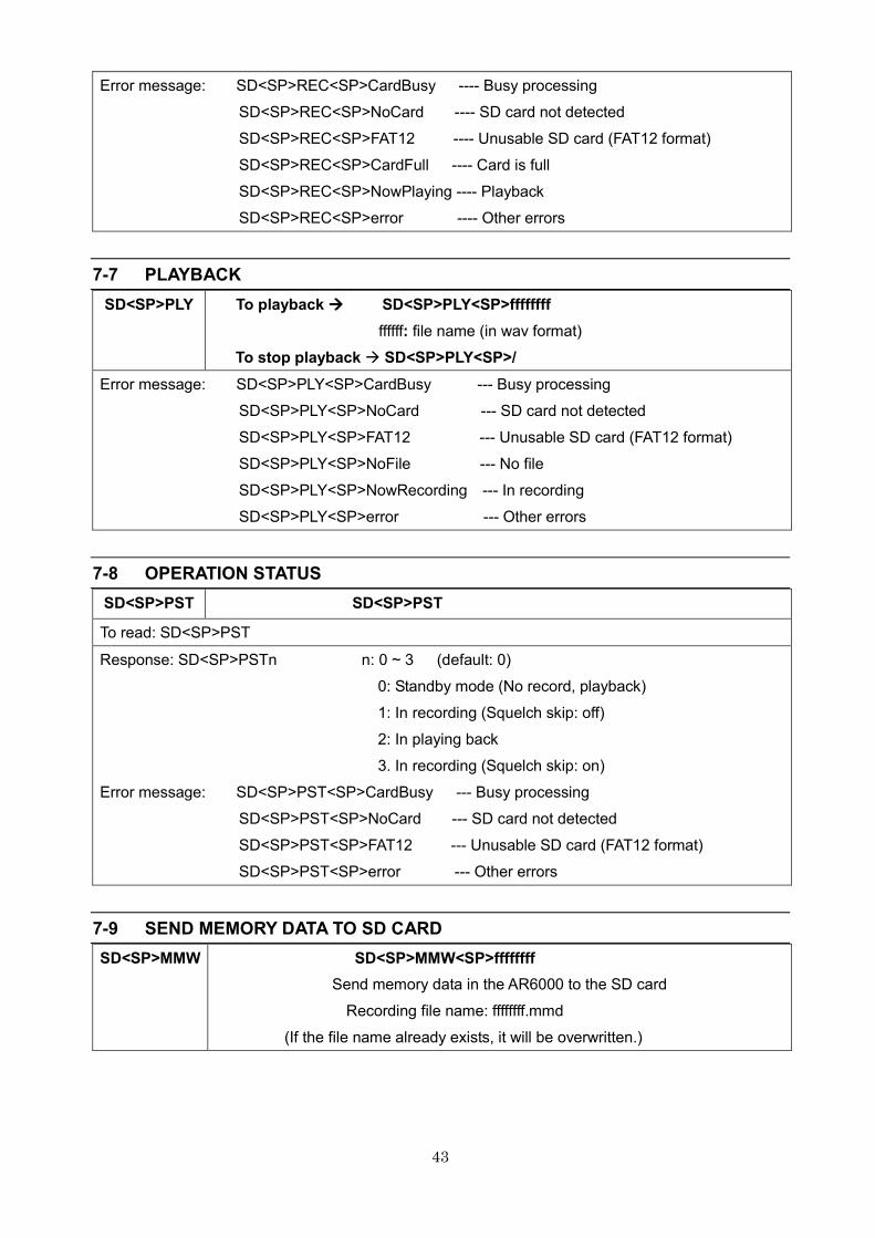
Error message: SD<SP>REC<SP>CardBusy ---- Busy processing
SD<SP>REC<SP>NoCard ---- SD card not detected
SD<SP>REC<SP>FAT12 ---- Unusable SD card (FAT12 format)
SD<SP>REC<SP>CardFull ---- Card is full
SD<SP>REC<SP>NowPlaying ---- Playback
SD<SP>REC<SP>error ---- Other errors
7-7 PLAYBACK
SD<SP>PLY
To playback ���� SD<SP>PLY<SP>ffffffff
ffffff: file name (in wav format)
To stop playback � SD<SP>PLY<SP>/
Error message: SD<SP>PLY<SP>CardBusy --- Busy processing
SD<SP>PLY<SP>NoCard --- SD card not detected
SD<SP>PLY<SP>FAT12 --- Unusable SD card (FAT12 format)
SD<SP>PLY<SP>NoFile --- No file
SD<SP>PLY<SP>NowRecording --- In recording
SD<SP>PLY<SP>error --- Other errors
7-8 OPERATION STATUS
SD<SP>PST SD<SP>PST
To read: SD<SP>PST
Response: SD<SP>PSTn n: 0 ~ 3 (default: 0)
0: Standby mode (No record, playback)
1: In recording (Squelch skip: off)
2: In playing back
3. In recording (Squelch skip: on)
Error message: SD<SP>PST<SP>CardBusy --- Busy processing
SD<SP>PST<SP>NoCard --- SD card not detected
SD<SP>PST<SP>FAT12 --- Unusable SD card (FAT12 format)
SD<SP>PST<SP>error --- Other errors
7-9 SEND MEMORY DATA TO SD CARD
SD<SP>MMW SD<SP>MMW<SP>ffffffff
Send memory data in the AR6000 to the SD card
Recording file name: ffffffff.mmd
(If the file name already exists, it will be overwritten.)
44
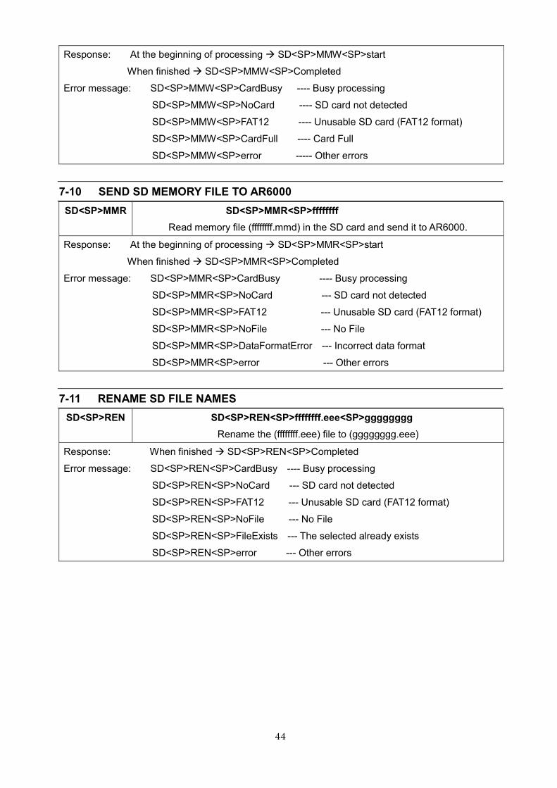
Response: At the beginning of processing � SD<SP>MMW<SP>start
When finished � SD<SP>MMW<SP>Completed
Error message: SD<SP>MMW<SP>CardBusy ---- Busy processing
SD<SP>MMW<SP>NoCard ---- SD card not detected
SD<SP>MMW<SP>FAT12 ---- Unusable SD card (FAT12 format)
SD<SP>MMW<SP>CardFull ---- Card Full
SD<SP>MMW<SP>error ----- Other errors
7-10 SEND SD MEMORY FILE TO AR6000
SD<SP>MMR SD<SP>MMR<SP>ffffffff
Read memory file (ffffffff.mmd) in the SD card and send it to AR6000.
Response: At the beginning of processing � SD<SP>MMR<SP>start
When finished � SD<SP>MMR<SP>Completed
Error message: SD<SP>MMR<SP>CardBusy ---- Busy processing
SD<SP>MMR<SP>NoCard --- SD card not detected
SD<SP>MMR<SP>FAT12 --- Unusable SD card (FAT12 format)
SD<SP>MMR<SP>NoFile --- No File
SD<SP>MMR<SP>DataFormatError --- Incorrect data format
SD<SP>MMR<SP>error --- Other errors
7-11 RENAME SD FILE NAMES
SD<SP>REN SD<SP>REN<SP>ffffffff.eee<SP>gggggggg
Rename the (ffffffff.eee) file to (gggggggg.eee)
Response: When finished � SD<SP>REN<SP>Completed
Error message: SD<SP>REN<SP>CardBusy ---- Busy processing
SD<SP>REN<SP>NoCard --- SD card not detected
SD<SP>REN<SP>FAT12 --- Unusable SD card (FAT12 format)
SD<SP>REN<SP>NoFile --- No File
SD<SP>REN<SP>FileExists --- The selected already exists
SD<SP>REN<SP>error --- Other errors
45
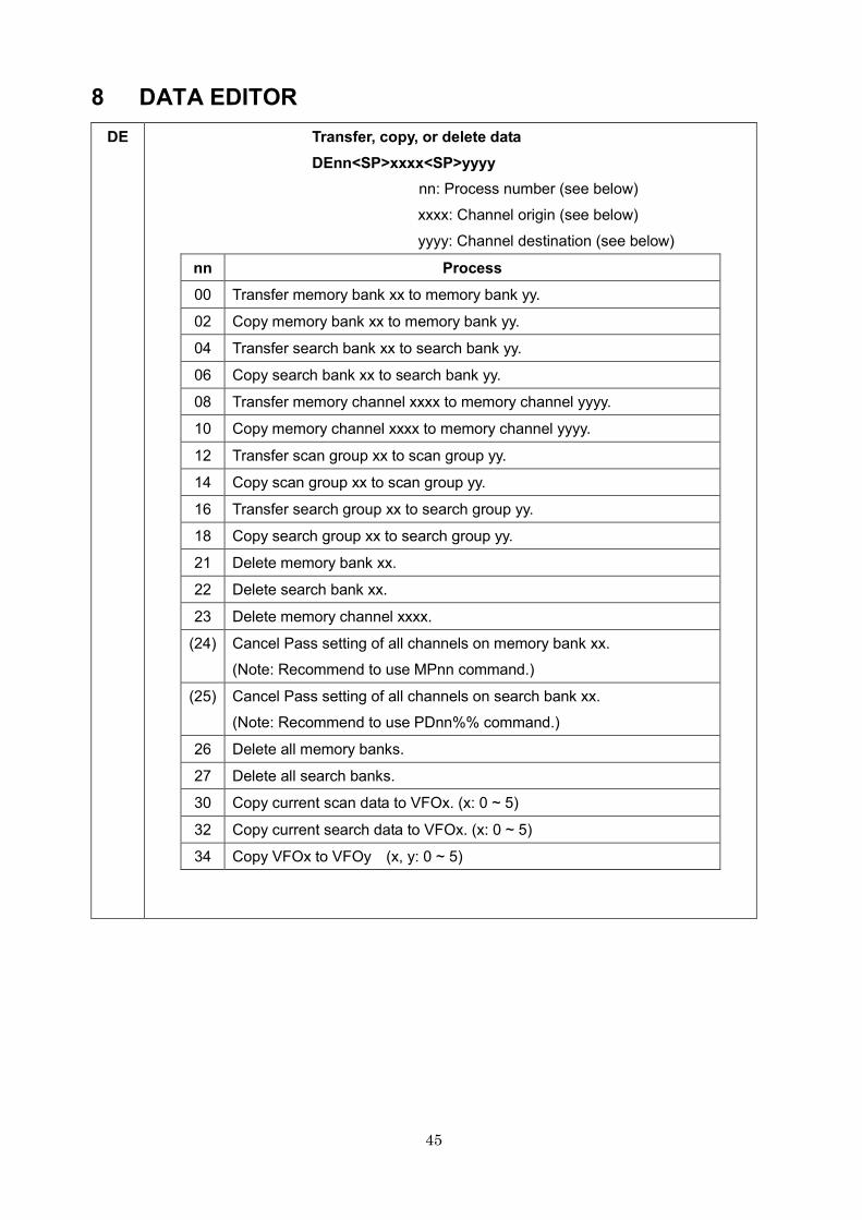
8 DATA EDITOR
DE
Transfer, copy, or delete data
DEnn<SP>xxxx<SP>yyyy
nn: Process number (see below)
xxxx: Channel origin (see below)
yyyy: Channel destination (see below)
nn Process
00 Transfer memory bank xx to memory bank yy.
02 Copy memory bank xx to memory bank yy.
04 Transfer search bank xx to search bank yy.
06 Copy search bank xx to search bank yy.
08 Transfer memory channel xxxx to memory channel yyyy.
10 Copy memory channel xxxx to memory channel yyyy.
12 Transfer scan group xx to scan group yy.
14 Copy scan group xx to scan group yy.
16 Transfer search group xx to search group yy.
18 Copy search group xx to search group yy.
21 Delete memory bank xx.
22 Delete search bank xx.
23 Delete memory channel xxxx.
(24) Cancel Pass setting of all channels on memory bank xx.
(Note: Recommend to use MPnn command.)
(25) Cancel Pass setting of all channels on search bank xx.
(Note: Recommend to use PDnn%% command.)
26 Delete all memory banks.
27 Delete all search banks.
30 Copy current scan data to VFOx. (x: 0 ~ 5)
32 Copy current search data to VFOx. (x: 0 ~ 5)
34 Copy VFOx to VFOy (x, y: 0 ~ 5)
46
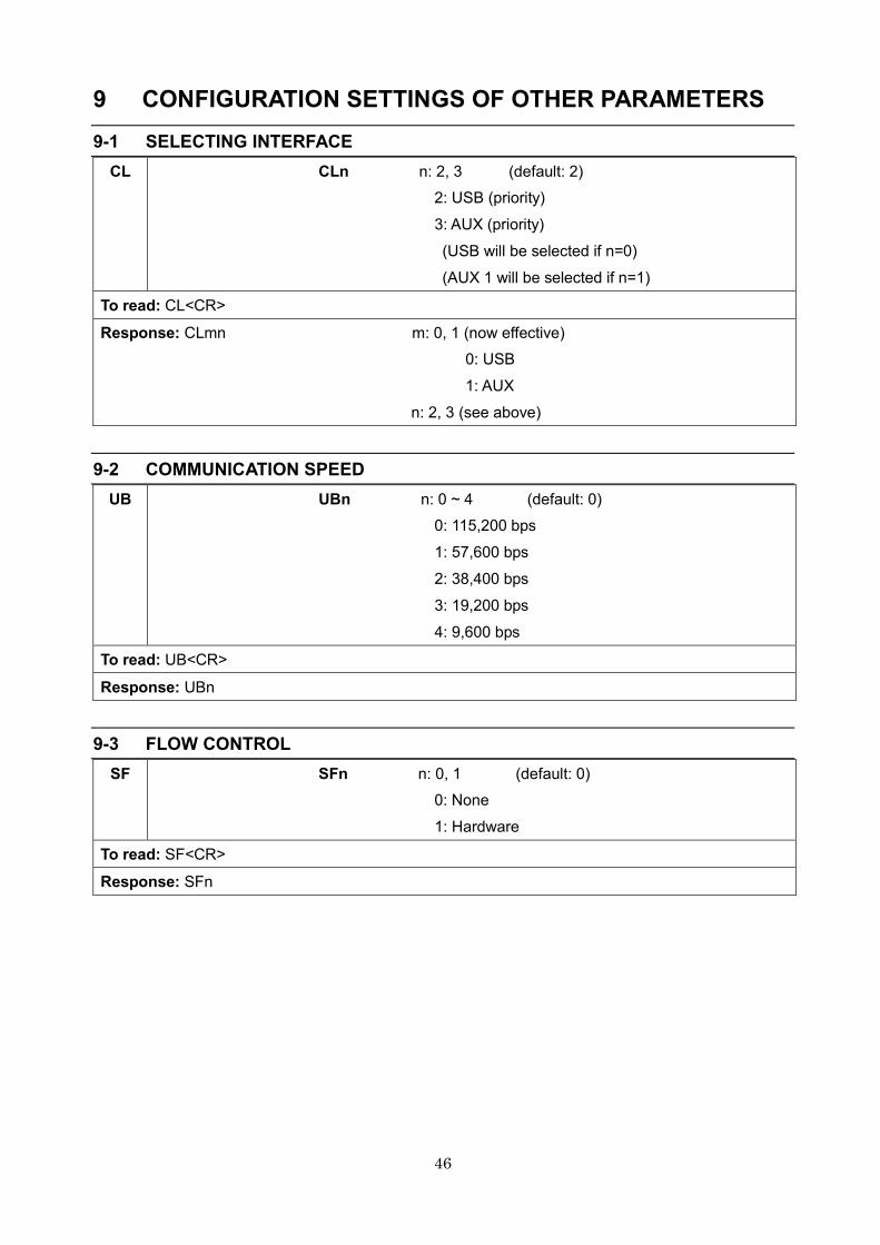
9 CONFIGURATION SETTINGS OF OTHER PARAMETERS
9-1 SELECTING INTERFACE
CL
CLn n: 2, 3 (default: 2)
2: USB (priority)
3: AUX (priority)
(USB will be selected if n=0)
(AUX 1 will be selected if n=1)
To read: CL<CR>
Response: CLmn m: 0, 1 (now effective)
0: USB
1: AUX
n: 2, 3 (see above)
9-2 COMMUNICATION SPEED
UB
UBn n: 0 ~ 4 (default: 0)
0: 115,200 bps
1: 57,600 bps
2: 38,400 bps
3: 19,200 bps
4: 9,600 bps
To read: UB<CR>
Response: UBn
9-3 FLOW CONTROL
SF
SFn n: 0, 1 (default: 0)
0: None
1: Hardware
To read: SF<CR>
Response: SFn
47
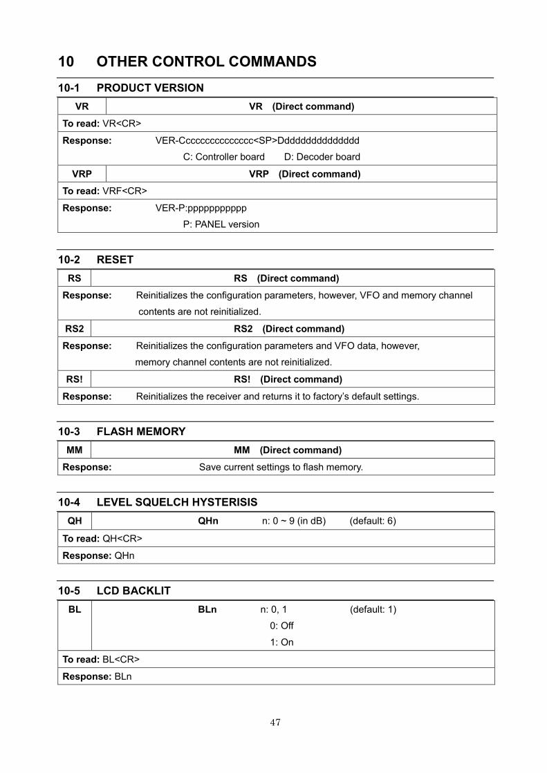
10 OTHER CONTROL COMMANDS
10-1 PRODUCT VERSION
VR VR (Direct command)
To read: VR<CR>
Response: VER-Ccccccccccccccc<SP>Ddddddddddddddd
C: Controller board D: Decoder board
VRP VRP (Direct command)
To read: VRF<CR>
Response: VER-P:ppppppppppp
P: PANEL version
10-2 RESET
RS RS (Direct command)
Response: Reinitializes the configuration parameters, however, VFO and memory channel
contents are not reinitialized.
RS2 RS2 (Direct command)
Response: Reinitializes the configuration parameters and VFO data, however,
memory channel contents are not reinitialized.
RS! RS! (Direct command)
Response: Reinitializes the receiver and returns it to factory’s default settings.
10-3 FLASH MEMORY
MM MM (Direct command)
Response: Save current settings to flash memory.
10-4 LEVEL SQUELCH HYSTERISIS
QH QHn n: 0 ~ 9 (in dB) (default: 6)
To read: QH<CR>
Response: QHn
10-5 LCD BACKLIT
BL BLn n: 0, 1 (default: 1)
0: Off
1: On
To read: BL<CR>
Response: BLn

48
10-6 BEEP LEVEL
BP BPn n: 0 ~ 7 (default: 1)
To read: BP<CR>
Response: BPn
10-7 BEEP TONE
BT BTn n: 1, 2
1: Beeps when command accepts
2: Beeps on error
10-8 CALENDER AND CLOCK
CK CKyyyymmddhhmmss
Yyyy: year
mm: month
dd: day
hh: hour (0 ~ 23)
mm: minute
ss: second
49
Manufacturer: AOR, LTD.
2-6-4, Misuji, Taito-Ku,
Tokyo, 111-0055, Japan
URL: www.aorja.com
US distributor: AOR USA, INC.
20655 S. Western Ave. Suite 112
Torrance, CA 90501
Phone: 310-787-8615
Fax: 310-787-8619
URL: www.aorusa.com
e-mail: [email protected]
May 14, 2013
Printed in Japan