aqwa-intro 14.5 l02 basics and theory
DESCRIPTION
Aqwa-Intro 14.5 L02 Basics and TheoryTRANSCRIPT

© 2012 ANSYS, Inc. March 21, 2013 1 Release 14.5
14.5 Release
Lecture 02
ANSYS Aqwa Basics & Theory
© 2012 ANSYS, Inc. March 21, 2013 2 Release 14.5
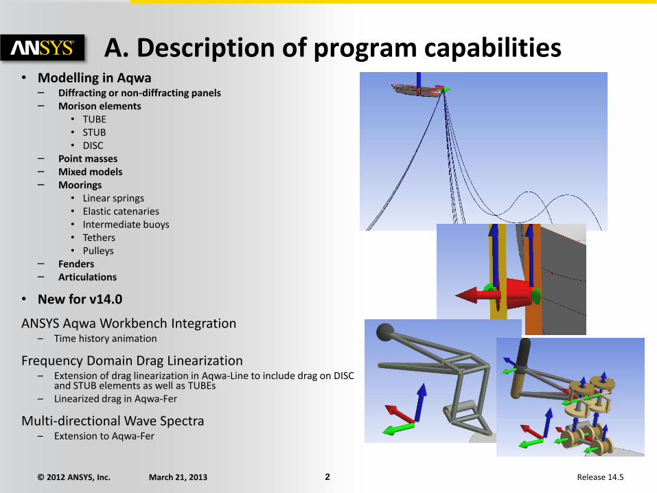
A. Description of program capabilities • Modelling in Aqwa
– Diffracting or non-diffracting panels – Morison elements
• TUBE • STUB • DISC
– Point masses – Mixed models – Moorings
• Linear springs • Elastic catenaries • Intermediate buoys • Tethers • Pulleys
– Fenders – Articulations
• New for v14.0
ANSYS Aqwa Workbench Integration – Time history animation
Frequency Domain Drag Linearization – Extension of drag linearization in Aqwa-Line to include drag on DISC
and STUB elements as well as TUBEs – Linearized drag in Aqwa-Fer
Multi-directional Wave Spectra – Extension to Aqwa-Fer

© 2012 ANSYS, Inc. March 21, 2013 3 Release 14.5
... Description of program capabilities
Modelling in Aqwa – Environment
• Waves
• Regular / irregular
• Time history
• Wave Spectra
• Pierson-Moskowitz
• JONSWAP
• User-defined
• Cross-swell
• Current
• Uniform
• Profile
• Wind
• Uniform
• Spectra
• Time history
© 2012 ANSYS, Inc. March 21, 2013 4 Release 14.5
... Description of program capabilities
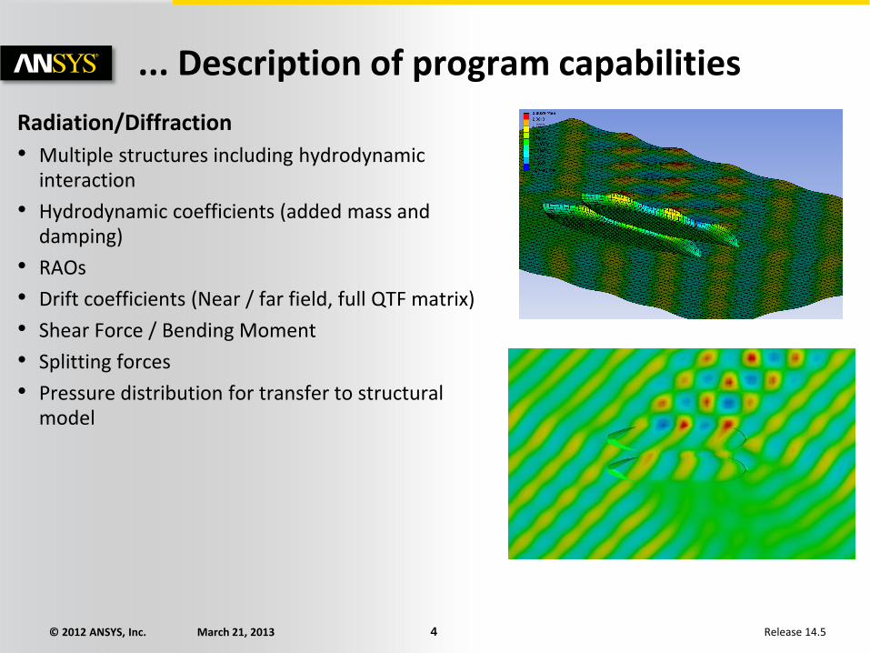
Radiation/Diffraction
• Multiple structures including hydrodynamic interaction
• Hydrodynamic coefficients (added mass and damping)
• RAOs
• Drift coefficients (Near / far field, full QTF matrix)
• Shear Force / Bending Moment
• Splitting forces
• Pressure distribution for transfer to structural model
© 2012 ANSYS, Inc. March 21, 2013 5 Release 14.5
... Description of program capabilities
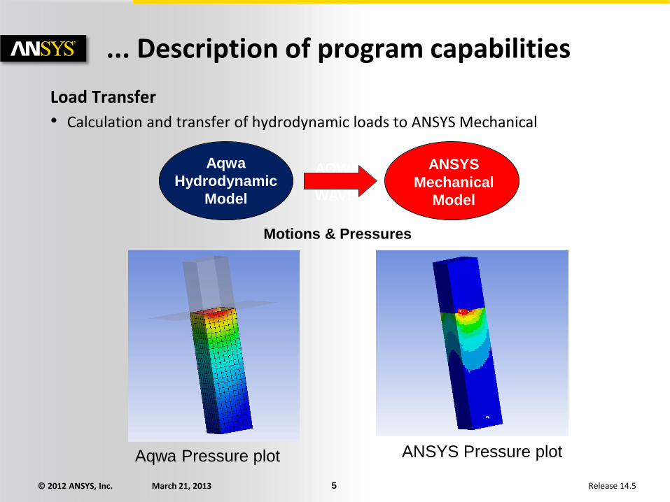
Load Transfer
• Calculation and transfer of hydrodynamic loads to ANSYS Mechanical
Aqwa
Hydrodynamic
Model
ANSYS
Mechanical
Model
Motions & Pressures
AQWA
WAVE
Aqwa Pressure plot ANSYS Pressure plot
© 2012 ANSYS, Inc. March 21, 2013 6 Release 14.5
... Description of program capabilities Equilibrium and Stability • Computes static equilibrium position for multiple environmental and mooring
configurations
• Preliminary mooring design
• Calculates static / dynamic stability
Frequency Domain • Significant motions at low frequency/wave frequency in frequency domain
• Permits rapid analysis using linearized parameters of mooring systems
• Graphs for response spectra / RAOs & other parameters
• Wave spreading and 2D spectra
Time Domain • Time-history analysis of multiple structures with irregular waves
• Can use full QTF matrix for shallow water conditions
• Import of wave height time history
• Input of forces via user-defined .dll
• Output of motions and forces
• Graphical and animation results

© 2012 ANSYS, Inc. March 21, 2013 7 Release 14.5
... Description of program capabilities
Large amplitude motions
• Non-linear time-history analysis with large (survival) waves
• Regular or irregular waves
• Integration of pressure over wetted surface
• Standard plus short crested wave option
Cable dynamics
• Additional cost item for more rigorous simulation of mooring line behaviour
• Provides full coupled vessel/mooring line analyses
Excel Interface
• Aqwa specific functions add-in for Excel for data and results retrieval, processing and report generation

© 2012 ANSYS, Inc. March 21, 2013 8 Release 14.5
...Description of program capabilities
Currently in Workbench (Release 14.0)
• Import of geometry from ANSYS DesignModeler
• Interactive data modification and editing
• Native meshing
• Diffraction/radiation analysis
• Definition of moorings, articulations and fenders
• Definition of environment
• Time domain analysis
• Graph plotting
• Wave surface and pressure contour plots
© 2012 ANSYS, Inc. March 21, 2013 9 Release 14.5
B. Aqwa Basics
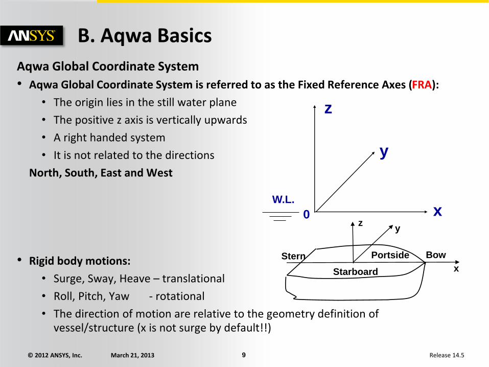
Aqwa Global Coordinate System
• Aqwa Global Coordinate System is referred to as the Fixed Reference Axes (FRA):
• The origin lies in the still water plane
• The positive z axis is vertically upwards
• A right handed system
• It is not related to the directions
North, South, East and West
• Rigid body motions:
• Surge, Sway, Heave – translational
• Roll, Pitch, Yaw - rotational
• The direction of motion are relative to the geometry definition of vessel/structure (x is not surge by default!!)
0
z
y
x W.L.
z
Portside Bow Stern
Starboard x
y

© 2012 ANSYS, Inc. March 21, 2013 10 Release 14.5
... Aqwa Basics
Hydrostatics
• Archimedes’s principle
• Buoyancy of an immersed body = weight of the fluid displaced
• Hydrostatic pressure
G: centre of gravity
B: centre of buoyancy
Buoyancy is the resultant of all hydrostatic force over wetted surface
0gZp G
Z0 B

© 2012 ANSYS, Inc. March 21, 2013 11 Release 14.5
... Aqwa Basics
Environmental direction in Aqwa
• The wave, wind and current directions are defined in Aqwa as the directions which they are travelling towards.
• The direction is defined as the angle between the wave (or current, wind) and the positive x axis measured anti-clockwise (For a ship facing forward to + x axis, this means 0 is astern seas and 180 is head seas).
• Directions in AQWA are input and output in degrees.
X axis
Wave direction (or current, wind)
positive angle
© 2012 ANSYS, Inc. March 21, 2013 12 Release 14.5
... Aqwa Basics
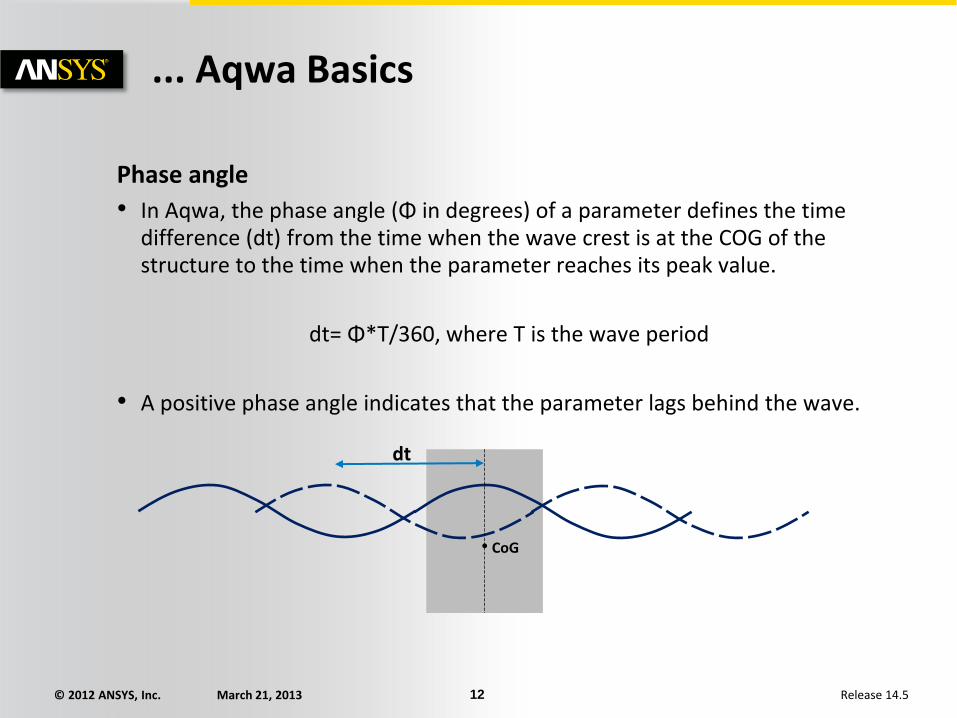
Phase angle
• In Aqwa, the phase angle (Φ in degrees) of a parameter defines the time difference (dt) from the time when the wave crest is at the COG of the structure to the time when the parameter reaches its peak value.
dt= Φ*T/360, where T is the wave period
• A positive phase angle indicates that the parameter lags behind the wave.
CoG
dt

© 2012 ANSYS, Inc. March 21, 2013 13 Release 14.5
... Aqwa Basics
Regular waves:
• Airy Waves (linear wave)
a = A cos (-ωt + kx)
(ω: frequency in radians/sec; k: wave number)
• Stokes 2nd Order Waves
a = A cos (-ωt + kx) + 0.5 k A² cos2(-ωt + kx)
© 2012 ANSYS, Inc. March 21, 2013 14 Release 14.5
... Aqwa Basics Irregular waves:
Wave spectrum types accepted in Aqwa are:
• Pierson-Moskowitz (PM) spectrum
• JONSWAP spectrum
• Gaussian
• User defined spectrum
• Cross Swell (using any of the above)
Irregular waves can be in the form of:
• Long crested waves; OR
• Short crested waves, i.e. a directional spread sea (available in some features so far)
© 2012 ANSYS, Inc. March 21, 2013 15 Release 14.5
... Aqwa Basics
Wind:
• Uniform wind
• Ochi and Shin wind spectrum
• API wind spectrum
• NPD wind spectrum
• User-defined wind spectrum
Current :
• Uniform velocity current
• Velocity profiled current

© 2012 ANSYS, Inc. March 21, 2013 16 Release 14.5
C. Theory in Aqwa Hydrodynamic Forces on Structures (on diffraction elements)
Fluid force
HydrodynamicHydrostatic
Wave exciting force
Ambient pressure
(incident wave or
Froude-Krylov force)
Effect of structure
on waves
(Diffraction)
Radiation force due
to structure motion
In-phase
(Added Mass)
Out-of-phase
(Radiation
damping)
F() C.xMa().x B().x
© 2012 ANSYS, Inc. March 21, 2013 17 Release 14.5
... Theory in Aqwa
Wave Forces for Diffracting Structures (modelled with plate elements)
• Incident wave force (Froude-Krylov force): from the pressure in the undisturbed waves.
• Diffraction force: due to stationary structure disturbing the incident waves.
• Radiation force: due to structure’s oscillation which generates waves.
• Drift force (net force due to high order effect)
© 2012 ANSYS, Inc. March 21, 2013 18 Release 14.5
... Theory in Aqwa
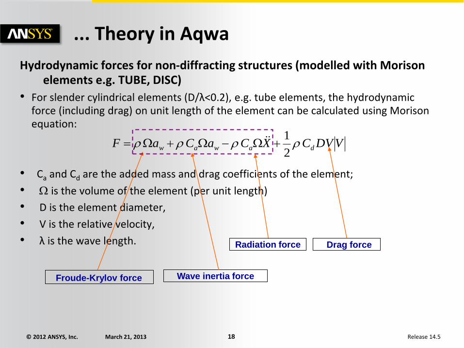
Hydrodynamic forces for non-diffracting structures (modelled with Morison elements e.g. TUBE, DISC)
• For slender cylindrical elements (D/λ<0.2), e.g. tube elements, the hydrodynamic force (including drag) on unit length of the element can be calculated using Morison equation:
• Ca and Cd are the added mass and drag coefficients of the element;
• is the volume of the element (per unit length)
• D is the element diameter,
• V is the relative velocity,
• λ is the wave length.
VDVCXCaCaF dawaw 2
1
Froude-Krylov force Wave inertia force
Radiation force Drag force
© 2012 ANSYS, Inc. March 21, 2013 19 Release 14.5
... Theory in Aqwa 3D Potential Theory solution • Viscous forces are not taken into account
• Ideal fluid, irrotational, incompressible
• Small wave elevation
Boundary condition problem is solved by satisfying • Body Boundary condition (Timman-Newman relations)
• Linearized free surface condition
• Sea bed boundary condition
• Radiation condition
• Solution for diffracted and radiated wave potentials uses a pulsating source distribution (zero speed solution with forward speed corrections)
Theory applies to finite depth and diffraction problem is solved in frequency domain
• Shallow water solution is available
Both 1st Order and 2nd Order wave forces are calculated • 2nd Order forces can be calculated from either near field or far field solutions
For more details on the exact formulations please refer to Aqwa Theory Manual
© 2012 ANSYS, Inc. March 21, 2013 20 Release 14.5
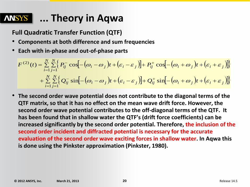
... Theory in Aqwa Full Quadratic Transfer Function (QTF)
• Components at both difference and sum frequencies
• Each with in-phase and out-of-phase parts
• The second order wave potential does not contribute to the diagonal terms of the QTF matrix, so that it has no effect on the mean wave drift force. However, the second order wave potential contributes to the off-diagonal terms of the QTF. It has been found that in shallow water the QTF’s (drift force coefficients) can be increased significantly by the second order potential. Therefore, the inclusion of the second order incident and diffracted potential is necessary for the accurate evaluation of the second order wave exciting forces in shallow water. In Aqwa this is done using the Pinkster approximation (Pinkster, 1980).
N
i
N
jjijiijjijiij
N
i
N
jjijiijjijiij
tQtQ
tPtPtF
1 1
1 1
)2(
sinsin
coscos)(

© 2012 ANSYS, Inc. March 21, 2013 21 Release 14.5
... Theory in Aqwa
Equations of Motions
• The response X of a structure in waves is calculated by solving the equation of motion in the frequency domain for unit wave amplitude:
• where Ms is structure mass
• Ma is added mass (frequency dependent)
• B is damping (frequency dependent)
• C is hydrostatic stiffness
• F is wave force (incident and diffracting forces).
)()(])())(([ 2 FXCBiMM as

© 2012 ANSYS, Inc. March 21, 2013 22 Release 14.5
... Theory in Aqwa
Long Story Short: Fluid force
HydrodynamicHydrostatic
Wave exciting force
Ambient pressure
(incident wave or
Froude-Krylov force)
Effect of structure
on waves
(Diffraction)
Radiation force due
to structure motion
In-phase
(Added Mass)
Out-of-phase
(Radiation
damping)
F() C.xMa().x B().x= + + + MS x’’
Structural Mass
© 2012 ANSYS, Inc. March 21, 2013 23 Release 14.5
D. Workbench HD Basics
WB HD shares common conventions with other Workbench products where appropriate
The basic interface consists of a number of areas
• Toolbars
• Analysis tree
• Details panel
• Graphical model representation and results presentation or textual results
© 2012 ANSYS, Inc. March 21, 2013 24 Release 14.5
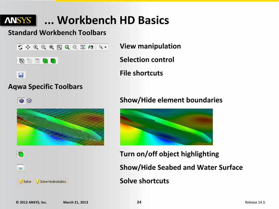
... Workbench HD Basics Standard Workbench Toolbars
View manipulation
Selection control
File shortcuts
Aqwa Specific Toolbars
Show/Hide element boundaries
Turn on/off object highlighting
Show/Hide Seabed and Water Surface
Solve shortcuts
© 2012 ANSYS, Inc. March 21, 2013 25 Release 14.5
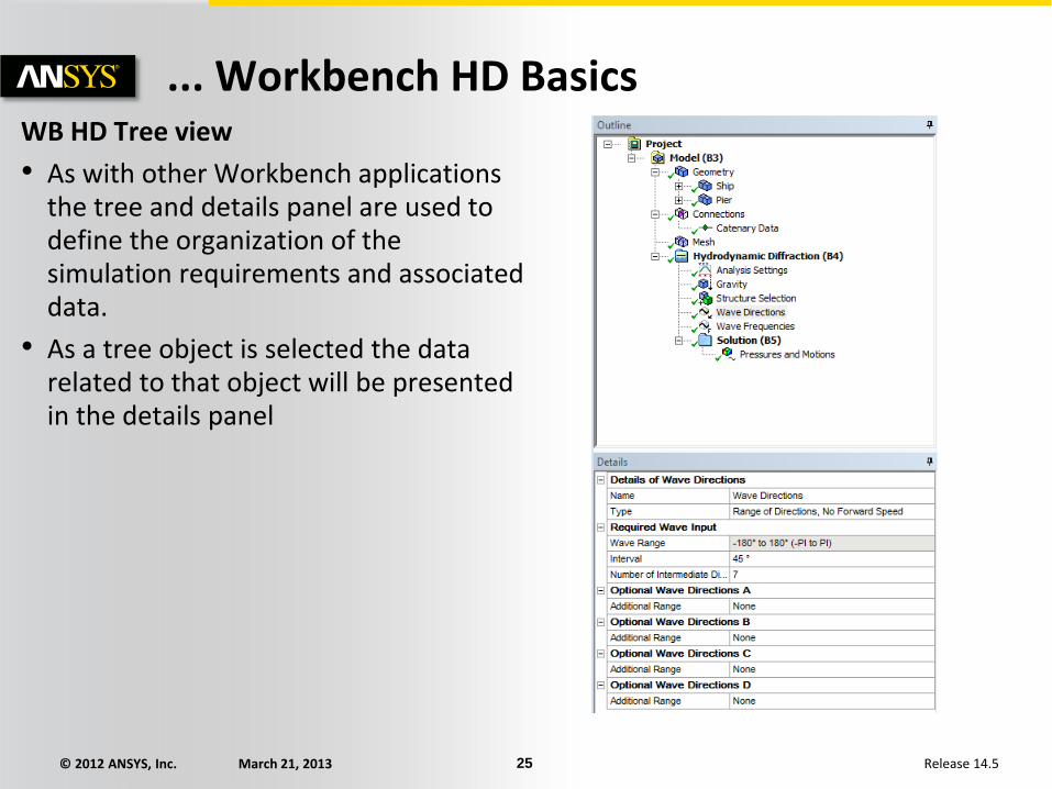
... Workbench HD Basics WB HD Tree view
• As with other Workbench applications the tree and details panel are used to define the organization of the simulation requirements and associated data.
• As a tree object is selected the data related to that object will be presented in the details panel

© 2012 ANSYS, Inc. March 21, 2013 26 Release 14.5
Bodies make up a Part. These are defined in
DesignModeler
Some Aqwa specific geometry based objects may
be added directly within AqwaWB
Objects that define the additional data required for
undertaking the hydrodynamic analysis
Results objects that may be added as required.
When selected they change the view in the main
visualization window
... Workbench HD Basics WB HD Tree view
Object excluded
Object included and up to date
Object changed since last solve, or no solve has been undertaken
Object is up to date for the Hydrostatic solve
Each vessel/structure is associated with a Part, in
this case Ship

© 2012 ANSYS, Inc. March 21, 2013 27 Release 14.5
... Workbench HD Basics Model and results presentation
• The main graphical area responds to what is selected in the object tree
– If geometry or mesh based information is selected then this will show a visualization of the information requested on the Geometry tab.
– If textual results are requested (such as Hydrostatic information) this will be shown on the Properties tab.
© 2012 ANSYS, Inc. March 21, 2013 28 Release 14.5
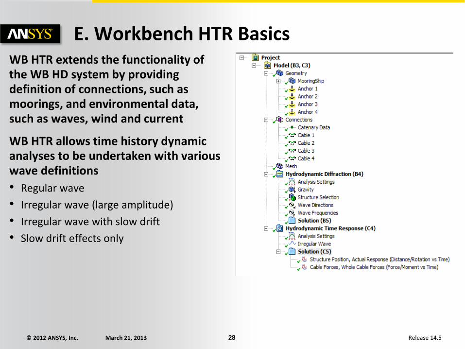
E. Workbench HTR Basics WB HTR extends the functionality of the WB HD system by providing definition of connections, such as moorings, and environmental data, such as waves, wind and current
WB HTR allows time history dynamic analyses to be undertaken with various wave definitions
• Regular wave
• Irregular wave (large amplitude)
• Irregular wave with slow drift
• Slow drift effects only
© 2012 ANSYS, Inc. March 21, 2013 29 Release 14.5
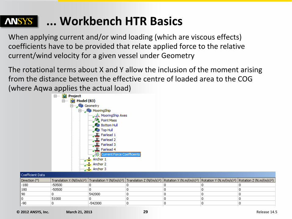
... Workbench HTR Basics When applying current and/or wind loading (which are viscous effects) coefficients have to be provided that relate applied force to the relative current/wind velocity for a given vessel under Geometry
The rotational terms about X and Y allow the inclusion of the moment arising from the distance between the effective centre of loaded area to the COG (where Aqwa applies the actual load)

© 2012 ANSYS, Inc. March 21, 2013 30 Release 14.5
... Workbench HTR Basics
Mooring lines require connection points on both the vessel geometry (fairleads) and at anchor locations (for moorings connected to ground)
Vessel connections are defined underneath the associated structure geometry entry. Connections can either be defined explicitly (as X, Y, Z coordinates in the global system), or as offsets from existing vertices in the model.

© 2012 ANSYS, Inc. March 21, 2013 31 Release 14.5
... Workbench HTR Basics Similarly anchor locations are defined at the Geometry level. Coordinates are always in the global system.
Mooring lines can then be added from Connections. These lines can be between two structures (vessels), or from a structure to a fixed point (anchor location). The Connection Stiffness shown here is typically used to model the effects of mooring lines on the HD system, where moorings cannot be explicitly utilized.
© 2012 ANSYS, Inc. March 21, 2013 32 Release 14.5
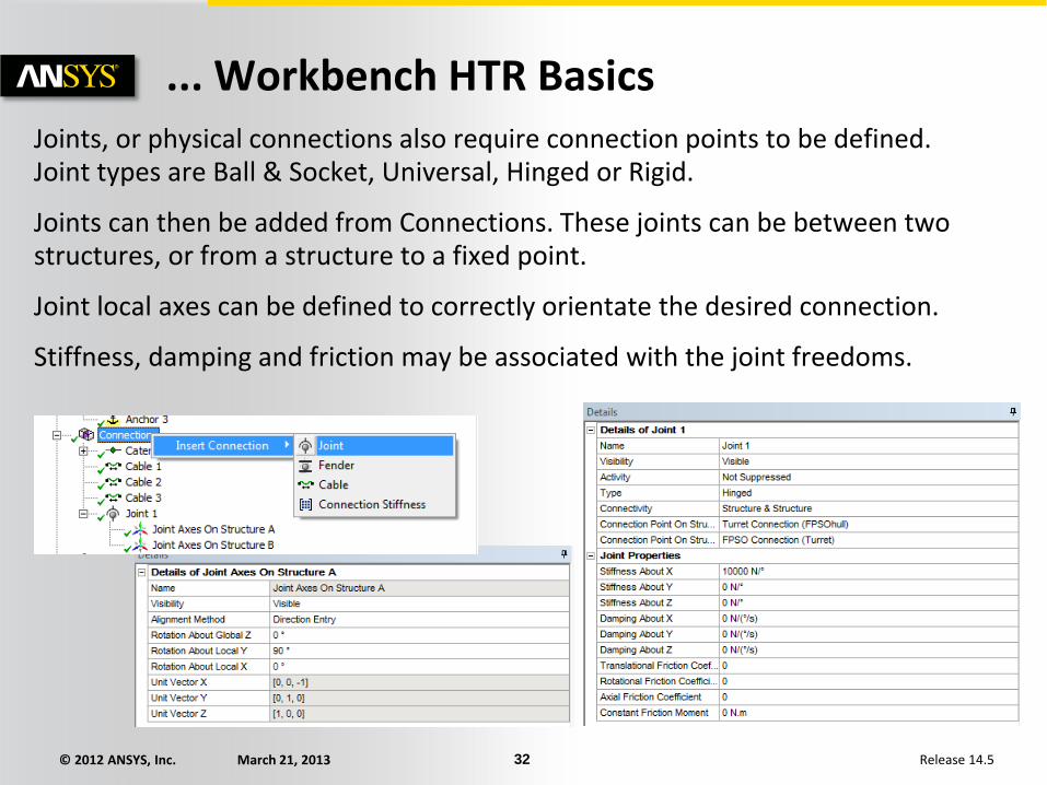
... Workbench HTR Basics Joints, or physical connections also require connection points to be defined. Joint types are Ball & Socket, Universal, Hinged or Rigid.
Joints can then be added from Connections. These joints can be between two structures, or from a structure to a fixed point.
Joint local axes can be defined to correctly orientate the desired connection.
Stiffness, damping and friction may be associated with the joint freedoms.

© 2012 ANSYS, Inc. March 21, 2013 33 Release 14.5
Workshop 2.1 – ANSYS Aqwa HD
Workshop 2.1 – ANSYS Aqwa Hydrodynamic Diffraction
Goal:
• Create a hydrodynamic radiation/diffraction model

© 2012 ANSYS, Inc. March 21, 2013 34 Release 14.5
Workshop 2.2 – ANSYS Aqwa HTR Workshop 2.2 – ANSYS Aqwa HydrodynamicTime Response
Goal:
• Create a mooring system and run a time history analysis
© 2012 ANSYS, Inc. March 21, 2013 35 Release 14.5
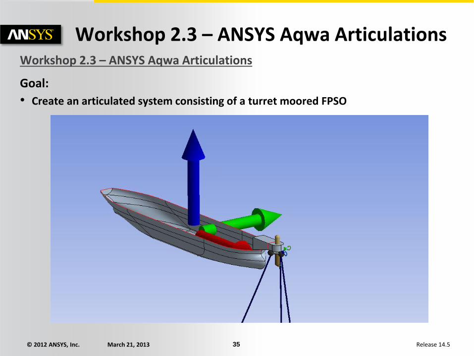
Workshop 2.3 – ANSYS Aqwa Articulations Workshop 2.3 – ANSYS Aqwa Articulations
Goal:
• Create an articulated system consisting of a turret moored FPSO