aquatherm north america design & planning … · aquatherm north american logistics center...
TRANSCRIPT
AQUATHERM NORTH AMERICADESIGN & PLANNING GUIDE

As we have grown from one man working out of his home garage in Germany forty years ago to the world’s largest and most advanced PP-R and PP-RP (RCT) pressure pipe manufacturer, Aquatherm has found success through constant improvement and by adapting to customer needs.
Aquatherm’s products were first introduced to the North American market in 2005 and have been widely used in a variety of projects since.
We stand by the philosophy that a better product is better for everyone, including our planet.
For detailed product information please refer to the Aquatherm North America Parts & Pricing Guide. For installation guidance, please see the Aquatherm North America Installer Manual.
NOTE: In keeping with the constant innovation of Aquatherm products, this guide is subject to periodic updates. The most current version of this guide can always be found at www.aquatherm.com and the information in the digital version always supersedes the print version. Please contact us at [email protected] or 801.805.6657 with any questions or comments you have regarding our piping systems.
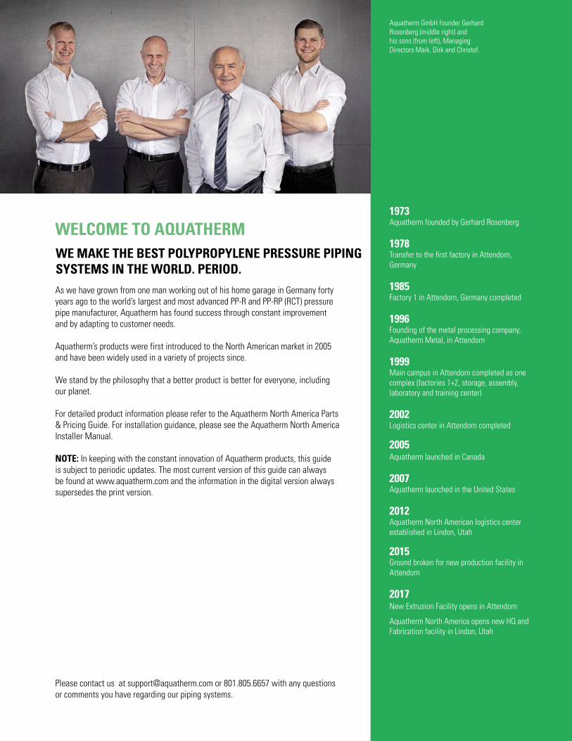
WE MAKE THE BEST POLYPROPYLENE PRESSURE PIPING SYSTEMS IN THE WORLD. PERIOD.
1973 Aquatherm founded by Gerhard Rosenberg
1978 Transfer to the first factory in Attendorn, Germany
1985Factory 1 in Attendorn, Germany completed
1996 Founding of the metal processing company, Aquatherm Metal, in Attendorn
1999Main campus in Attendorn completed as one complex (factories 1+2, storage, assembly, laboratory and training center)
2002 Logistics center in Attendorn completed
2005Aquatherm launched in Canada
2007Aquatherm launched in the United States
2012Aquatherm North American logistics center established in Lindon, Utah
2015Ground broken for new production facility in Attendorn
2017New Extrusion Facility opens in Attendorn
Aquatherm North America opens new HQ and Fabrication facility in Lindon, Utah
WELCOME TO AQUATHERM
Aquatherm GmbH founder Gerhard Rosenberg (middle right) and his sons (from left), Managing Directors Maik, Dirk and Christof.

TABLE OF CONTENTSFEATURES1.01 – Aquatherm PP-R and PP-RP (RCT) piping systems
1.02 – Standard dimension ratio
1.02 – Nominal imperial sizing
1.04 – aquatherm blue pipe®
1.06 – aquatherm green pipe®
1.08 – Multi-layer, faser-composite
1.09 – aquatherm lilac pipe®
1.10 – PP-R and PP-RP (RCT)
1.11 – Ecological advantages
1.12 – System features
1.14 – Installation advantages
QUALITY ASSURANCE2.01 – Quality control
2.02 – Fabrication services
2.02 – Customized support
2.02 – Shipping and on-site inspection
2.03 – Labeling
2.03 – Care and handling of pipes and fittings
2.04 – Standards, regulations and listings
PLANNING3.01 – Planning and engineering with Aquatherm
3.01 – Determining compatibility
3.02 – Special applications
3.04 – Integration with other systems
3.05 – Flame spread / Smoke developed
3.06 – Using the I-Codes
3.06 – Using the IAPMO codes
3.07 – System protection
3.07 – Recommended flow rates
3.08 – Flow velocity and head (friction) loss
3.08 – Pipe sizing by head loss
3.08 – Recommended sizing and flow velocity
3.30 – Equivalent lengths of fittings (ft)
3.36 – Maximum pull force

Note: This version of the Aquatherm catalog has been modified for distribution in Canada and the United States by Aquatherm LP and Aquatherm Corp. The name of the Aquatherm catalog has been changed to the Aquatherm Design & Planning Guide. The text has been translated and edited for greater clarity and the data has been converted from metric to imperial units. Some content has been added to address issues specific to North America. As such, Aquatherm GmbH assumes no responsibility for these modifications, and assumes no liability for any problems that may arise from them. In addition, Aquatherm LP and Aquatherm Corp. do not warranty the accuracy, reliability or completeness of any information contained herein. In the case of discrepancies between this document and any information published or produced by Aquatherm GmbH, the material published by Aquatherm GmbH shall be considered the authoritative source. This edition supersedes all previous editions of the Aquatherm catalog, and will be replaced by the next edition.
INSTALLATION PRINCIPLES4.01 – Heat fusion connections
4.02 – Training and installation
4.03 – Socket fusion
4.03 – Mechanically assisted fusion
4.03 – Butt fusion
4.03 – Outlet fusion
4.03 – Hot tapping
4.03 – Electrofusion
4.04 – Supporting the pipe
4.06 – Linear expansion
4.10 – Expansion controls
4.13 – Fusion outlets
4.14 – Transition fittings
4.15 – Flushing the pipes
4.15 – UV protection
4.15 – Freeze protection
4.15 – Grounding
4.16 – Pressure test

Aquatherm piping systems
Standard dimension ratio
Nominal imperial sizing
aquatherm blue pipe®
aquatherm green pipe®
Multi-layer, faser-composite
aquatherm lilac pipe®
fusiolen® PP-R and PP-RP (RCT)
Ecological advantages
System features
Installation advantages
1FEATURES
1.01
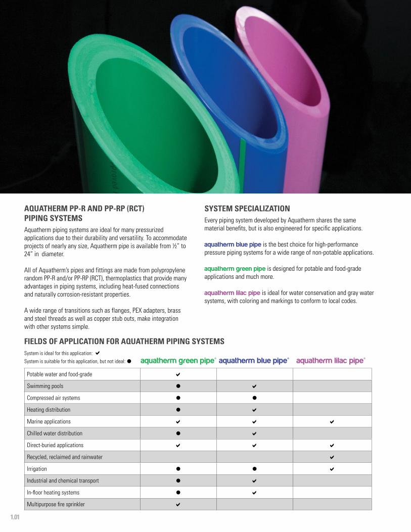
FIELDS OF APPLICATION FOR AQUATHERM PIPING SYSTEMSSystem is ideal for this application: System is suitable for this application, but not ideal: l aquatherm green pipe® aquatherm blue pipe® aquatherm lilac pipe®
Potable water and food-grade
Swimming pools l
Compressed air systems l l
Heating distribution l
Marine applications
Chilled water distribution l
Direct-buried applications
Recycled, reclaimed and rainwater
Irrigation l l
Industrial and chemical transport l
In-floor heating systems l
Multipurpose fire sprinkler
SYSTEM SPECIALIZATIONEvery piping system developed by Aquatherm shares the same material benefits, but is also engineered for specific applications.
aquatherm blue pipe is the best choice for high-performance pressure piping systems for a wide range of non-potable applications.
aquatherm green pipe is designed for potable and food-grade applications and much more.
aquatherm lilac pipe is ideal for water conservation and gray water systems, with coloring and markings to conform to local codes.
AQUATHERM PP-R AND PP-RP (RCT) PIPING SYSTEMSAquatherm piping systems are ideal for many pressurized applications due to their durability and versatility. To accommodate projects of nearly any size, Aquatherm pipe is available from ½” to 24” in diameter.
All of Aquatherm’s pipes and fittings are made from polypropylene random PP-R and/or PP-RP (RCT), thermoplastics that provide many advantages in piping systems, including heat-fused connections and naturally corrosion-resistant properties.
A wide range of transitions such as flanges, PEX adapters, brass and steel threads as well as copper stub outs, make integration with other systems simple.
1.02
FEATURES
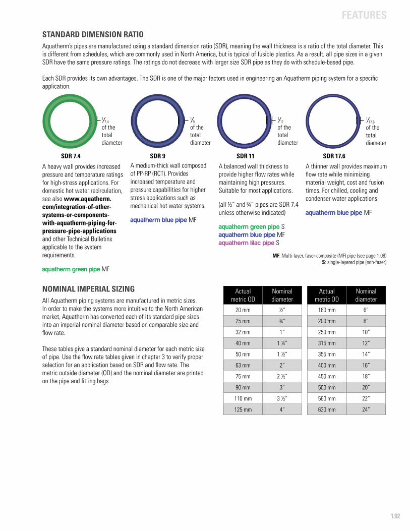
NOMINAL IMPERIAL SIZINGAll Aquatherm piping systems are manufactured in metric sizes. In order to make the systems more intuitive to the North American market, Aquatherm has converted each of its standard pipe sizes into an imperial nominal diameter based on comparable size and flow rate.
These tables give a standard nominal diameter for each metric size of pipe. Use the flow rate tables given in chapter 3 to verify proper selection for an application based on SDR and flow rate. The metric outside diameter (OD) and the nominal diameter are printed on the pipe and fitting bags.
Actualmetric OD
Nominal diameter
20 mm ½”
25 mm ¾”
32 mm 1”
40 mm 1 ¼”
50 mm 1 ½”
63 mm 2”
75 mm 2 ½”
90 mm 3”
110 mm 3 ½”
125 mm 4”
Actualmetric OD
Nominal diameter
160 mm 6”
200 mm 8”
250 mm 10”
315 mm 12”
355 mm 14”
400 mm 16”
450 mm 18”
500 mm 20”
560 mm 22”
630 mm 24”
STANDARD DIMENSION RATIO Aquatherm’s pipes are manufactured using a standard dimension ratio (SDR), meaning the wall thickness is a ratio of the total diameter. This is different from schedules, which are commonly used in North America, but is typical of fusible plastics. As a result, all pipe sizes in a given SDR have the same pressure ratings. The ratings do not decrease with larger size SDR pipe as they do with schedule-based pipe.
Each SDR provides its own advantages. The SDR is one of the major factors used in engineering an Aquatherm piping system for a specific application.
SDR 7.4
1/ 7.4 of the total diameter
SDR 11SDR 9
1/ 11
of the total diameter
1/ 9of the total diameter
SDR 17.6
1/ 17.6
of the total diameter
A heavy wall provides increased pressure and temperature ratings for high-stress applications. For domestic hot water recirculation, see also www.aquatherm.com/integration-of-other-systems-or-components-with-aquatherm-piping-for-pressure-pipe-applications and other Technical Bulletins applicable to the system requirements.
aquatherm green pipe MF
A balanced wall thickness to provide higher flow rates while maintaining high pressures. Suitable for most applications.
(all ½” and ¾” pipes are SDR 7.4 unless otherwise indicated)
aquatherm green pipe Saquatherm blue pipe MFaquatherm lilac pipe S
A thinner wall provides maximum flow rate while minimizing material weight, cost and fusion times. For chilled, cooling and condenser water applications.
aquatherm blue pipe MF
MF: Multi-layer, faser-composite (MF) pipe (see page 1.08)S: single-layered pipe (non-faser)
A medium-thick wall composed of PP-RP (RCT). Provides increased temperature and pressure capabilities for higher stress applications such as mechanical hot water systems.
aquatherm blue pipe MF

1.03
FEATURES
aquatherm green pipe® SDR 7.4 MF
PipeND
Capacitygal/ft
Weight lb/ft
w/water lb/ft
½” 0.01 0.11 0.22¾” 0.02 0.17 0.34
1” 0.03 0.26 0.51
1 ¼” 0.05 0.41 0.83
1 ½” 0.08 0.64 1.31
2” 0.13 1.00 2.08
2 ½” 0.19 1.42 3.00
3” 0.27 2.03 4.28
3 ½” 0.40 3.04 6.37
4” 0.52 4.17 8.50
6” 0.85 6.54 13.62
8” 1.33 10.06 21.14
10” 2.08 15.74 33.07
12” 3.34 20.71 48.53
14” 4.24 26.29 61.61
aquatherm green pipe® pipe SDR 7.4 S / SDR 11 S aquatherm lilac pipe® SDR 7.4 S / SDR 11 S
PipeND
Capacitygal/ft
Weightlb/ft
w/water lb/ft
½” 0.02 0.10 0.24
¾” 0.03 0.16 0.38
1” 0.04 0.18 0.51
1 ¼” 0.07 0.28 0.86
1 ½” 0.11 0.43 1.35
2” 0.17 0.68 2.10
2 ½” 0.24 0.95 2.95
3” 0.34 1.37 4.20
3 ½” 0.51 2.10 6.35
4” 0.66 2.63 8.13
6” 1.08 4.30 13.308” 1.70 6.70 20.86
10” 2.65 10.42 32.49
12” 4.20 17.24 52.23
14” 5.34 20.99 65.47
16“ 6.79 27.77 84.33
18“ 8.57 35.15 106.54The following items are supplied in coils
½” 0.01 0.07 0.15
¾” 0.03 0.11 0.36
1” 0.04 0.17 0.50
aquatherm blue pipe® SDR 7.4 MF / SDR 11 MF
PipeND
Capacitygal/ft
Weightlb/ft
w/ waterlb/ft
½” 0.01 0.11 0.22
¾” 0.02 0.16 0.36
1” 0.04 0.19 0.55
1 ¼” 0.07 0.29 0.85
1 ½” 0.11 0.45 1.32
2” 0.17 0.71 2.10
2 ½” 0.24 1.00 2.97
3” 0.34 1.44 4.30
3 ½” 0.51 2.13 6.39
4” 0.66 2.76 8.27
6” 1.08 4.51 13.52
8” 1.69 7.03 21.12
PipeND
Capacitygal/ft
Weightlb/ft
w/ water lb/ft
4” 0.78 1.80 8.30
6” 1.27 2.92 13.52
8” 1.99 4.56 21.10
10” 3.11 7.09 32.95
12” 4.93 11.23 52.30
14” 6.27 14.23 66.43
16“ 7.95 18.06 84.30
18“ 10.07 22.82 106.69
20“ 12.42 28.22 131.70
22“ 15.60 32.25 162.16
24“ 19.73 44.63 209.01
PipeND
Capacitygal/ft
Weightlb/ft
w/ water lb/ft
1” 0.039 0.22 0.55
1 ¼” 0.061 0.35 0.85
1 ½” 0.095 0.54 1.33
2” 0.151 0.85 2.11
2 ½” 0.214 1.20 2.99
3” 0.308 1.73 4.30
3 ½” 0.461 2.56 6.41
4” 0.595 3.31 8.27
6” 0.975 5.41 13.50
8” 1.522 8.45 21.20
10” 2.384 13.20 33.00
12” 3.782 20.90 52.50
14” 4.801 26.50 66.60
PipeND
Capacitygal/ft
Weightlb/ft
w/ waterlb/ft
10” 2.65 10.93 32.97
12” 4.20 17.24 52.23
14” 5.39 22.16 67.03
16“ 6.79 27.77 84.31
18“ 8.57 35.15 106.56
The following items are supplied in coils
½” 0.02 0.07 0.21
¾” 0.03 0.11 0.33
1” 0.04 0.17 0.53
aquatherm blue pipe® SDR 17.6 MF
aquatherm blue pipe® SDR 9 MF
WEIGHTS AND CAPACITIES

1.04
FEATURES
A BETTER CHOICE FOR HEATING AND COOLING AND INDUSTRIAL PIPING APPLICATIONS
aquatherm blue pipe is specifically engineered for applications beyond potable water installations. It offers a tougher, longer lasting, more environmentally responsible solution to other non-potable pressure systems.
In addition to the general advantages of the PP-R and PP-RP (RCT) pipe system, aquatherm blue pipe offers higher volumetric flow rates due to thinner walls and is high-heat stabilized for short exposures to temperatures beyond the intended design. PP-R and PP-RP (RCT) piping is also extremely resistant to impact, corrosion, and seismic stresses.
aquatherm blue pipe uses the same socket fittings and tools as aquatherm green pipe, making installation simple and easy. The dimensions range from ½” to 24” ND. aquatherm blue pipe is also available with UV protection for outdoor installations and multi-layer, faser-composite (MF) technology, which reduces linear expansion.
CORROSION AND SCALE RESISTANCEWhile other piping materials lose performance over time to scaling and corrosion, Aquatherm’s PP-R and PP-RP (RCT) material resists any form of change to the material wall. Even after decades of use, the Aquatherm pipe will retain its original flow characteristics. This prevents the loss of efficiency that occurs when using a pipe that can scale or corrode and will save energy over the life of the system. No chemical treatments are needed to protect the aquatherm blue pipe, saving maintenance costs and reducing waste.
ADVANTAGES• Resistant to most chemicals• Excellent flow rate• Fast, heat-fused connections• Light, impact-resistant material• Corrosion-free pipe and fittings• Natural sound and heat insulation• Long-lasting • Fully recyclable• High-heat stabilized
aquatherm blue pipe®This signature PP-R and PP-RP (RCT) pipe offering is an ideal alternative to metal, is
EXPANSION CONTROLLED, CORROSION-FREE AND BETTERthan the piping material it replaces.
Corrosion and scaling can reduce the inside of steel pipes by an average of 3% per year, resulting in lost efficiency and up to 10% increased pumping energy annually. This can add up to thousands of dollars in hidden energy costs over the life of the system.
Aquatherm’s PP-R and PP-RP (RCT) pipes don’t corrode or scale, so they continue delivering efficiency and performance year after year.
Sample specifications for aquatherm blue pipe can be found at www.aquatherm.com/specifications-and-submittals.
Fields of application
+F°
SteelPP-R and PP-RP (RCT)

1.05
FEATURES
HEATING DISTRIBUTIONFor commercial, industrial and residential use, aquatherm blue pipe with multi-layer, faser-composite (MF) is an ideal choice due to its reduced linear expansion and resistance to corrosion, which increase performance and extend service life. Non-faser coils are also available for use in snow-melt applications in concrete or asphalt.
CHILLED WATER DISTRIBUTIONFor residential, commercial and industrial use, aquatherm blue pipe has a natural insulation value that helps reduce heat gain and often eliminates problems with condensation, making it an excellent choice for cooling towers and condenser water.
INDUSTRIAL APPLICATIONSFor the processing and transport of aggressive mediums and materials, aquatherm green pipe and aquatherm blue pipe resist many types of chemicals.
RADIANT HEATING SYSTEMS Aquatherm’s fused connections, low pressure drops and 8-to-1 bending radius (non-MF only) make for a safe and efficient installation. Aquatherm’s fusion outlets allow for an extended manifold layout, which helps reduce costs and improve performance.
GEOTHERMALWhile all Aquatherm pipe can be safely buried in soil, sand or concrete, aquatherm blue pipe is available in larger diameters and has heat stabilization, making it a perfect match for geothermal applications. Aquatherm pipe is also suitable for directional boring.
CONDENSED WATER SYSTEMSaquatherm blue pipe is able to withstand the more corrosive environment of open loop condenser water systems, where higher dissolved gas concentrations are found in the water, and more aggressive treatment chemicals may be needed for prevention of bacterial growth such as legionella.
Drawings, CAD/Revit files can be found at www.aquatherm.com/design-tools.
1.06
FEATURES
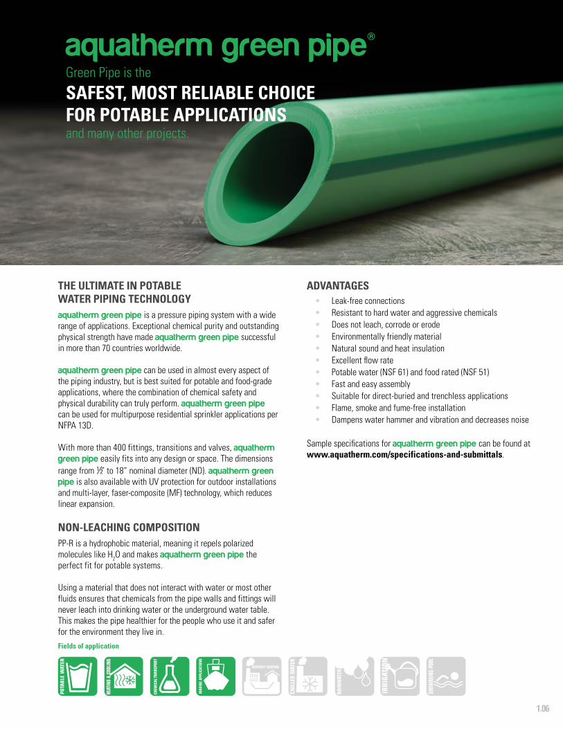
THE ULTIMATE IN POTABLE WATER PIPING TECHNOLOGYaquatherm green pipe is a pressure piping system with a wide range of applications. Exceptional chemical purity and outstanding physical strength have made aquatherm green pipe successful in more than 70 countries worldwide.
aquatherm green pipe can be used in almost every aspect of the piping industry, but is best suited for potable and food-grade applications, where the combination of chemical safety and physical durability can truly perform. aquatherm green pipe can be used for multipurpose residential sprinkler applications per NFPA 13D.
With more than 400 fittings, transitions and valves, aquatherm green pipe easily fits into any design or space. The dimensions range from ½” to 18” nominal diameter (ND). aquatherm green pipe is also available with UV protection for outdoor installations and multi-layer, faser-composite (MF) technology, which reduces linear expansion.
NON-LEACHING COMPOSITIONPP-R is a hydrophobic material, meaning it repels polarized molecules like H2O and makes aquatherm green pipe the perfect fit for potable systems.
Using a material that does not interact with water or most other fluids ensures that chemicals from the pipe walls and fittings will never leach into drinking water or the underground water table. This makes the pipe healthier for the people who use it and safer for the environment they live in.
ADVANTAGES• Leak-free connections• Resistant to hard water and aggressive chemicals• Does not leach, corrode or erode• Environmentally friendly material• Natural sound and heat insulation• Excellent flow rate• Potable water (NSF 61) and food rated (NSF 51)• Fast and easy assembly• Suitable for direct-buried and trenchless applications• Flame, smoke and fume-free installation• Dampens water hammer and vibration and decreases noise
Sample specifications for aquatherm green pipe can be found at www.aquatherm.com/specifications-and-submittals.
aquatherm green pipe®Green Pipe is the
SAFEST, MOST RELIABLE CHOICE FOR POTABLE APPLICATIONSand many other projects.
Fields of application
1.07
FEATURES
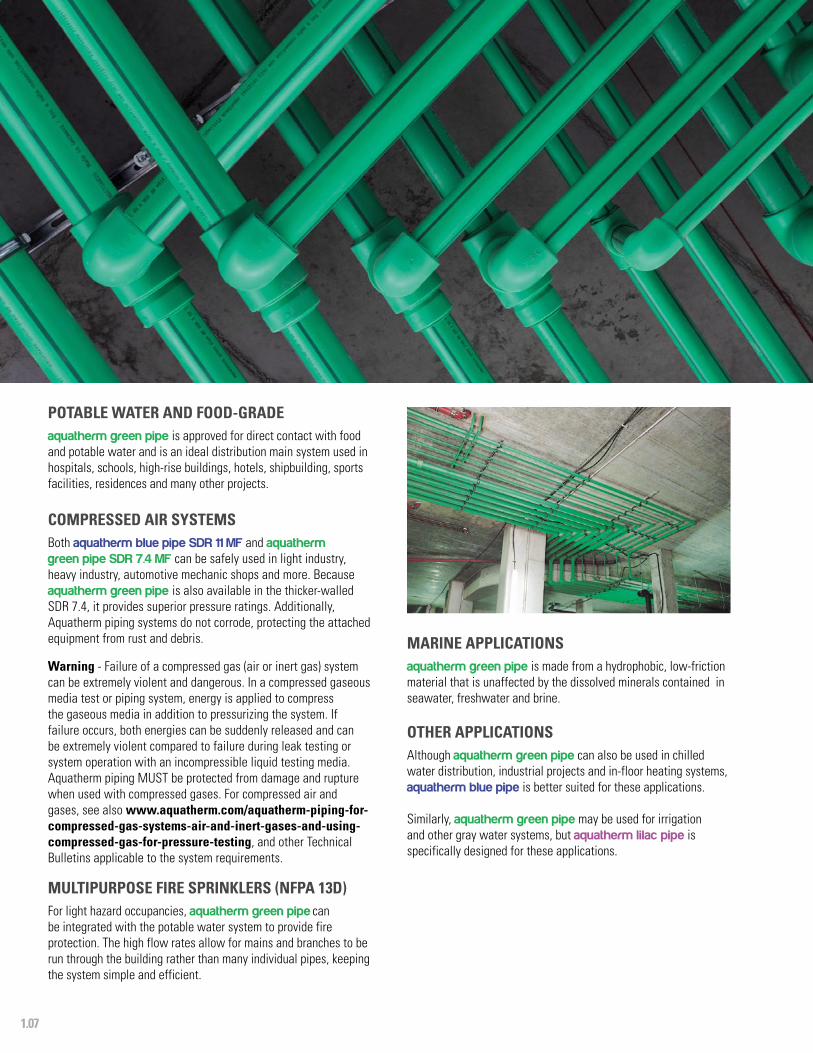
POTABLE WATER AND FOOD-GRADE aquatherm green pipe is approved for direct contact with food and potable water and is an ideal distribution main system used in hospitals, schools, high-rise buildings, hotels, shipbuilding, sports facilities, residences and many other projects.
COMPRESSED AIR SYSTEMSBoth aquatherm blue pipe SDR 11 MF and aquatherm green pipe SDR 7.4 MF can be safely used in light industry, heavy industry, automotive mechanic shops and more. Because aquatherm green pipe is also available in the thicker-walled SDR 7.4, it provides superior pressure ratings. Additionally, Aquatherm piping systems do not corrode, protecting the attached equipment from rust and debris.
Warning - Failure of a compressed gas (air or inert gas) system can be extremely violent and dangerous. In a compressed gaseous media test or piping system, energy is applied to compress the gaseous media in addition to pressurizing the system. If failure occurs, both energies can be suddenly released and can be extremely violent compared to failure during leak testing or system operation with an incompressible liquid testing media. Aquatherm piping MUST be protected from damage and rupture when used with compressed gases. For compressed air and gases, see also www.aquatherm.com/aquatherm-piping-for-compressed-gas-systems-air-and-inert-gases-and-using-compressed-gas-for-pressure-testing, and other Technical Bulletins applicable to the system requirements.
MULTIPURPOSE FIRE SPRINKLERS (NFPA 13D)For light hazard occupancies, aquatherm green pipe can be integrated with the potable water system to provide fire protection. The high flow rates allow for mains and branches to be run through the building rather than many individual pipes, keeping the system simple and efficient.
MARINE APPLICATIONSaquatherm green pipe is made from a hydrophobic, low-friction material that is unaffected by the dissolved minerals contained in seawater, freshwater and brine.
OTHER APPLICATIONSAlthough aquatherm green pipe can also be used in chilled water distribution, industrial projects and in-floor heating systems, aquatherm blue pipe is better suited for these applications.
Similarly, aquatherm green pipe may be used for irrigation and other gray water systems, but aquatherm lilac pipe is specifically designed for these applications.

1.08
FEATURES
MULTI-LAYER, FASER-COMPOSITE (MF) TECHNOLOGYTo increase maximum operating temperatures and improve overall performance, Aquatherm has developed a multi-layer, faser-composite (MF) extrusion process.
The result is a middle layer in the pipe that is a mixture of glass fibers and Aquatherm’s proprietary fusiolen. This layer allows the pipe to remain rigid at high temperatures and significantly reduce linear expansion.
Along with the benefit of reduced expansion, Aquatherm MF pipes are still flexible and require fewer and smaller expansion controls. They can also be buried without any expansion controls or thrust blocking, as the weight of the soil will restrict any movement. Anchors may be required where the pipe penetrates a wall or foundation.
The MF technology allows for improved systems without sacrificing any of the other advantages of the pipe.
MF Layer
MULTI-LAYER, FASER-COMPOSITE TECHNOLOGYPP-R or PP-RP (RCT) Layer
PP-R or PP-RP (RCT) LayerMF Layer
PP-R Layer
PP-R Layer
ADDITIONAL BENEFITSIn addition to reduced linear expansion, pipes made using the MF process also have the following advantages:
• Higher flow rate due to increased inner diameter • Fewer supports needed• Less weight
The low concentration of glass fibers in the pipe does not interfere with the fusion process or the recycling process, so all other aspects of installation and use remain the same as with non-MF Aquatherm pipes.
1.09
FEATURES
aquatherm lilac pipe®
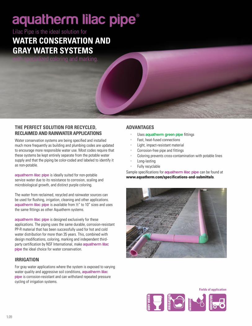
THE PERFECT SOLUTION FOR RECYCLED, RECLAIMED AND RAINWATER APPLICATIONSWater conservation systems are being specified and installed much more frequently as building and plumbing codes are updated to encourage more responsible water use. Most codes require that these systems be kept entirely separate from the potable water supply and that the piping be color-coded and labeled to identify it as non-potable.
aquatherm lilac pipe is ideally suited for non-potable service water due to its resistance to corrosion, scaling and microbiological growth, and distinct purple coloring.
The water from reclaimed, recycled and rainwater sources can be used for flushing, irrigation, cleaning and other applications. aquatherm lilac pipe is available from ½” to 10” sizes and uses the same fittings as other Aquatherm systems.
aquatherm lilac pipe is designed exclusively for these applications. The piping uses the same durable, corrosion-resistant PP-R material that has been successfully used for hot and cold water distribution for more than 35 years. This, combined with design modifications, coloring, marking and independent third-party certification by NSF International, make aquatherm lilac pipe the ideal choice for water conservation.
IRRIGATIONFor gray water applications where the system is exposed to varying water quality and aggressive soil conditions, aquatherm lilac pipe is corrosion-resistant and can withstand repeated pressure cycling of irrigation systems.
Lilac Pipe is the ideal solution for
WATER CONSERVATION AND GRAY WATER SYSTEMS with specialized coloring and marking.
ADVANTAGES• Uses aquatherm green pipe fittings• Fast, heat-fused connections• Light, impact-resistant material• Corrosion-free pipe and fittings• Coloring prevents cross-contamination with potable lines• Long-lasting • Fully recyclable
Sample specifications for aquatherm lilac pipe can be found at www.aquatherm.com/specifications-and-submittals.
Fields of application

1.10
FEATURES
fusiolen® PP-R, PP-RP (RCT)All Aquatherm pipes and fittings are made with a specialized polypropylene-random PP-R or PP-RP (RCT) resin, fusiolen.
fusiolen is both physically and chemically resistant to the abuse that can damage other materials. It is also a low-friction material, protecting it from abrasion and reducing pressure loss.
The superior fusion properties of fusiolen result in a permanent, homogeneous connection that is chemically indistinguishable from the rest of the material.
MATERIAL BENEFITSPolypropylene is a thermoplastic polymer that is made up of chains of carbon and hydrogen.
fusiolen is a blend of long and short hydrocarbon chains, resulting in a material that is both tough and flexible. This allows it to resist physical impact and stress.
As a hydrophobic material, fusiolen does not interact with water. It does not corrode or erode and will not leach into the water supply.
fusiolen has natural insulation properties that allow it to absorb the force from pressure surges and dampen the noise created by water flow and hydraulic shock.
Raw fusiolen PP and PP-RCT granules.
SUPERIOR FUSION PROPERTIESfusiolen is engineered to have an ideal melt index for socket fusion, butt fusion, and electrofusion resulting in connections that are strong and homogeneous.
fusiolen does not burn or change during fusion, so the actual point of fusion is chemically indistinguishable from the rest. This prevents weaknesses and cracking in the joints.
HIGH TEMPERATURE STABILIZATION fusiolen is heat stabilized, giving it a much higher safety factor than traditional polypropylene.
Under extreme temperatures, fusiolen will last six times longer without material degradation. This means that occasional exposure to high temperatures due to mechanical failure won’t damage the Aquatherm pipe systems.
ADVANTAGES OF FUSIOLEN PP-R AND PP-RP (RCT)
• Optimized melt index for better fusion connections
• Opaque coloring prevents microbiological buildup
• Non-leaching • Natural insulation properties • Non-corroding • Heat-stabilized

1.11
FEATURES
ENVIRONMENTAL QUALITY ASSURANCE AND LONGEVITYTo ensure its environmental compatibility, the base PP-R and PP-RP (RCT) material and additives (color pigments and stabilizers) are extensively tested by Aquatherm’s own laboratory as well as independent researchers to ensure that nothing harmful is ever put into our pipes.
Aquatherm pipes will last for more than 60 years within the design parameters provided in this catalog. This eliminates the environmental impact of repairs, mold, leaks and other problems caused by piping failure. By using components that last longer, buildings can be made safer and more sustainable.
From initial production all the way through installation, system decommissioning and recycling, Aquatherm is as green as piping systems get. Visit www.aquatherm.com/aquatherm-leed-v4-white-paper to download the Aquatherm LEED v4 White Paper, and view our EPD at: www.info.nsf.org/Certified/Sustain/ProdCert/EPD10069.pdf.
ECOLOGICAL ADVANTAGES
• Directly contributes to LEED v4 credits • Improved efficiency • No toxic materials such as PVC, BPAs,
dioxins, phthalates or VOCs • Fully recyclable pipe and fittings • Extended service life • Free of heavy metals • Chemically inert • Emission-free installation
NOT NEW TO ENERGY EFFICIENCY AND SUSTAINABILITYAquatherm was green before “green” was a topic in North America. The company evolved out of a garage in 1973 when Gerhard Rosenberg found a better piping system for in-floor radiant heating. Ever since that day, Aquatherm has operated with energy efficiency and sustainability as guiding values. We believe that ecological and economic interest should go hand in hand, both in the production and installation of our products.
In fact, Aquatherm North America takes these values seriously enough to have undertaken the extensive expense and effort of establishing and verifying its environmental benefits. We then got our life cycle assessment (LCA) and environmental product declaration (EPD) studies certified by NSF Sustainability. This resulted in Aquatherm polypropylene piping systems becoming the first in North America that directly contribute to LEED v4 credits.
LOW-IMPACT LIFE CYCLE fusiolen PP-R and PP-RP (RCT) is fully recyclable and can be ground, melted and re-used in car parts, home products, food packaging, medical equipment and other applications. There are no harmful waste products created by the processing or disposal of fusiolen. The pipe and fittings made with fusiolen have an estimated service life of more than 60 years. As a result, Aquatherm’s pipe systems rarely require maintenance or costly repairs.

1.12
FEATURES
SYSTEM FEATURES
HEAT FUSION CONNECTIONSThe connections in an Aquatherm piping system are made using heat fusion, a simple process which actually turns the pipe and fitting into a single piece of PP-R or PP-RP (RCT).
There are no solders, solvents or glues added to the connection, eliminating weak points and harmful chemicals from the system.
60+ YEAR LIFE SPANAquatherm piping systems resist the scaling and corrosion that reduce the performance of other piping systems.
The walls of the PP-R and PP-RP (RCT) piping systems generate less friction than other systems, eliminating the abrasion that can cause pinhole leaks and shorten the life cycle of the pipe.
The heat fusion joints maintain the same properties as the pipe itself, so physical stresses will not damage their integrity.
Aquatherm piping systems last longer with less maintenance than other systems, adding greater value to each installation. With proper design, Aquatherm systems can last for more than 60 years.
POTABLE WATER RATINGAquatherm piping systems meet the requirements of NSF Standard 14 and aquatherm green pipe meets NSF Standard 61, showing that it is safe for direct contact with drinking water.
aquatherm green pipe has been tested to NSF 51 and is acceptable for direct food contact and food processing applications.
Aquatherm piping systems meet the stringent requirements for strength, material quality, dimension, damage resistance, marking and quality control of ASTM F2389 and CSA B137.11.
ADVANTAGES• Chemically inert material• Application-specific engineering• Corrosion and scale resistant• Incidental freezing tolerance• 10-year warranty• Natural sound insulation• Consistent quality
APPLICATION-SPECIFIC ENGINEERINGAquatherm piping systems are engineered for optimal performance based on the application type.
• aquatherm green pipe is rated for potability, and comes with MF and non-MF variations to optimize efficiency and economics.
• aquatherm blue pipe is high-heat stabilized to have a higher safety factor while maintaining superior flow rates.
• aquatherm lilac pipe is designed without multi-layer, faser-composite, providing the highest value for gray water installations.
FULL SYSTEM RANGEAquatherm piping systems can be used in nearly any pressure application and range in size from ½” to 24”. This allows installers to use one type of pipe for an entire system rather than mixing multiple materials and joining methods.
An entire project can be done using Aquatherm pipes, eliminating the need for multiple tool sets and maintenance programs.
Transitions to ANSI flanges, NPT threads and PEX piping make combining Aquatherm pipe with other systems and components simple and easy.
1.13
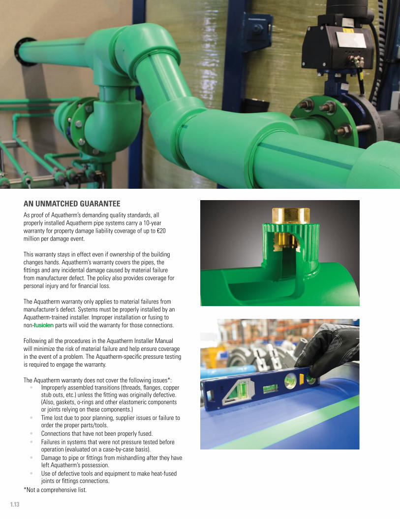
AN UNMATCHED GUARANTEEAs proof of Aquatherm’s demanding quality standards, all properly installed Aquatherm pipe systems carry a 10-year warranty for property damage liability coverage of up to €20 million per damage event.
This warranty stays in effect even if ownership of the building changes hands. Aquatherm’s warranty covers the pipes, the fittings and any incidental damage caused by material failure from manufacturer defect. The policy also provides coverage for personal injury and for financial loss.
The Aquatherm warranty only applies to material failures from manufacturer’s defect. Systems must be properly installed by an Aquatherm-trained installer. Improper installation or fusing to non-fusiolen parts will void the warranty for those connections.
Following all the procedures in the Aquatherm Installer Manual will minimize the risk of material failure and help ensure coverage in the event of a problem. The Aquatherm-specific pressure testing is required to engage the warranty.
The Aquatherm warranty does not cover the following issues*:• Improperly assembled transitions (threads, flanges, copper
stub outs, etc.) unless the fitting was originally defective. (Also, gaskets, o-rings and other elastomeric components or joints relying on these components.)
• Time lost due to poor planning, supplier issues or failure to order the proper parts/tools.
• Connections that have not been properly fused.• Failures in systems that were not pressure tested before
operation (evaluated on a case-by-case basis).• Damage to pipe or fittings from mishandling after they have
left Aquatherm’s possession. • Use of defective tools and equipment to make heat-fused
joints or fittings connections.*Not a comprehensive list.
1.14
FEATURES
ADVANTAGES• Lightweight pipe and fittings• Durable material• Full system compatibility• Rigid hanging pipe• Flexible lengths and connections• Easily prefabricated• Consistent results• Simple expansion control
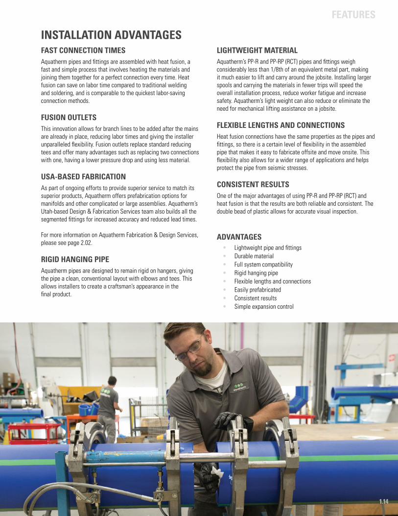
INSTALLATION ADVANTAGES FAST CONNECTION TIMESAquatherm pipes and fittings are assembled with heat fusion, a fast and simple process that involves heating the materials and joining them together for a perfect connection every time. Heat fusion can save on labor time compared to traditional welding and soldering, and is comparable to the quickest labor-saving connection methods.
FUSION OUTLETSThis innovation allows for branch lines to be added after the mains are already in place, reducing labor times and giving the installer unparalleled flexibility. Fusion outlets replace standard reducing tees and offer many advantages such as replacing two connections with one, having a lower pressure drop and using less material.
USA-BASED FABRICATIONAs part of ongoing efforts to provide superior service to match its superior products, Aquatherm offers prefabrication options for manifolds and other complicated or large assemblies. Aquatherm’s Utah-based Design & Fabrication Services team also builds all the segmented fittings for increased accuracy and reduced lead times. For more information on Aquatherm Fabrication & Design Services, please see page 2.02.
RIGID HANGING PIPEAquatherm pipes are designed to remain rigid on hangers, giving the pipe a clean, conventional layout with elbows and tees. This allows installers to create a craftsman’s appearance in the final product.
LIGHTWEIGHT MATERIALAquatherm’s PP-R and PP-RP (RCT) pipes and fittings weigh considerably less than 1/8th of an equivalent metal part, making it much easier to lift and carry around the jobsite. Installing larger spools and carrying the materials in fewer trips will speed the overall installation process, reduce worker fatigue and increase safety. Aquatherm’s light weight can also reduce or eliminate the need for mechanical lifting assistance on a jobsite.
FLEXIBLE LENGTHS AND CONNECTIONSHeat fusion connections have the same properties as the pipes and fittings, so there is a certain level of flexibility in the assembled pipe that makes it easy to fabricate offsite and move onsite. This flexibility also allows for a wider range of applications and helps protect the pipe from seismic stresses.
CONSISTENT RESULTSOne of the major advantages of using PP-R and PP-RP (RCT) and heat fusion is that the results are both reliable and consistent. The double bead of plastic allows for accurate visual inspection.

2Quality control
Aquatherm in North America
Customized support
Shipping and on-site inspection
Labeling
Care and handling
Standards, regulations and listings
QUALITY ASSURANCE
2.01
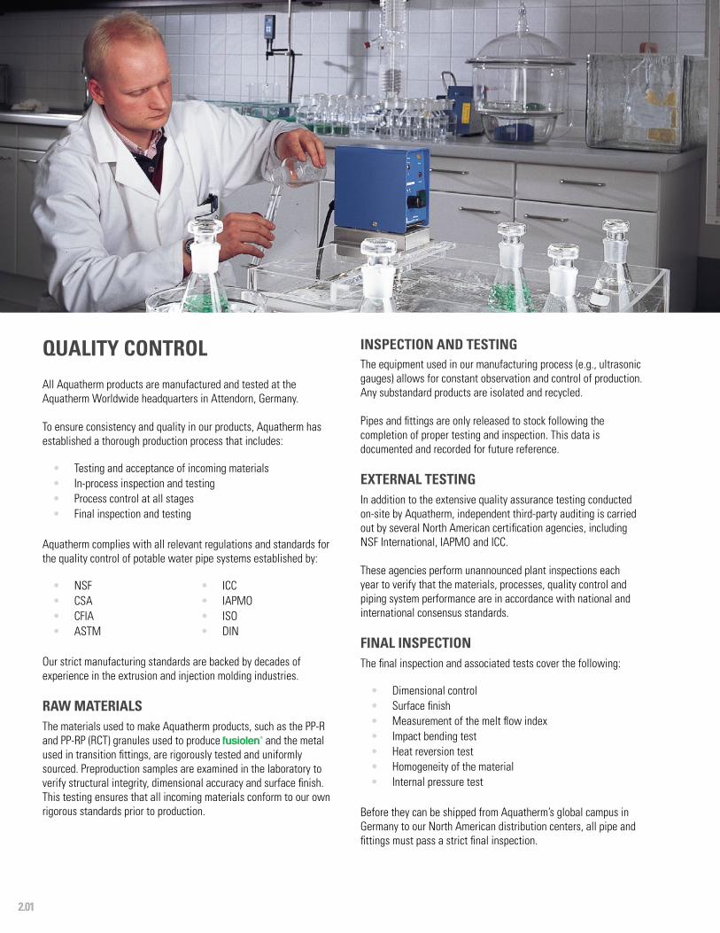
INSPECTION AND TESTING The equipment used in our manufacturing process (e.g., ultrasonic gauges) allows for constant observation and control of production. Any substandard products are isolated and recycled.
Pipes and fittings are only released to stock following the completion of proper testing and inspection. This data is documented and recorded for future reference.
EXTERNAL TESTINGIn addition to the extensive quality assurance testing conducted on-site by Aquatherm, independent third-party auditing is carried out by several North American certification agencies, including NSF International, IAPMO and ICC.
These agencies perform unannounced plant inspections each year to verify that the materials, processes, quality control and piping system performance are in accordance with national and international consensus standards.
FINAL INSPECTIONThe final inspection and associated tests cover the following:
• Dimensional control• Surface finish• Measurement of the melt flow index• Impact bending test• Heat reversion test• Homogeneity of the material• Internal pressure test
Before they can be shipped from Aquatherm’s global campus in Germany to our North American distribution centers, all pipe and fittings must pass a strict final inspection.
All Aquatherm products are manufactured and tested at the Aquatherm Worldwide headquarters in Attendorn, Germany.
To ensure consistency and quality in our products, Aquatherm has established a thorough production process that includes:
• Testing and acceptance of incoming materials• In-process inspection and testing • Process control at all stages• Final inspection and testing
Aquatherm complies with all relevant regulations and standards for the quality control of potable water pipe systems established by:
• NSF• CSA• CFIA• ASTM
• ICC• IAPMO• ISO• DIN
Our strict manufacturing standards are backed by decades of experience in the extrusion and injection molding industries.
RAW MATERIALSThe materials used to make Aquatherm products, such as the PP-R and PP-RP (RCT) granules used to produce fusiolen® and the metal used in transition fittings, are rigorously tested and uniformly sourced. Preproduction samples are examined in the laboratory to verify structural integrity, dimensional accuracy and surface finish. This testing ensures that all incoming materials conform to our own rigorous standards prior to production.
QUALITY CONTROL
2.02
QUALITY ASSURANCE
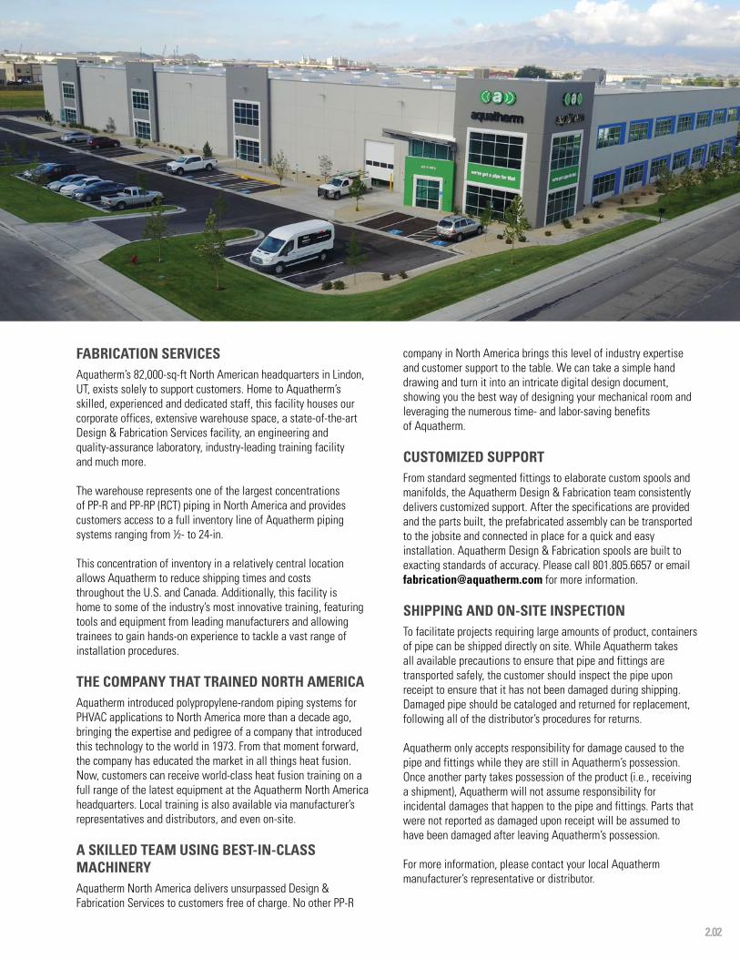
FABRICATION SERVICESAquatherm’s 82,000-sq-ft North American headquarters in Lindon, UT, exists solely to support customers. Home to Aquatherm’s skilled, experienced and dedicated staff, this facility houses our corporate offices, extensive warehouse space, a state-of-the-art Design & Fabrication Services facility, an engineering and quality-assurance laboratory, industry-leading training facility and much more.
The warehouse represents one of the largest concentrations of PP-R and PP-RP (RCT) piping in North America and provides customers access to a full inventory line of Aquatherm piping systems ranging from ½- to 24-in.
This concentration of inventory in a relatively central location allows Aquatherm to reduce shipping times and costs throughout the U.S. and Canada. Additionally, this facility is home to some of the industry’s most innovative training, featuring tools and equipment from leading manufacturers and allowing trainees to gain hands-on experience to tackle a vast range of installation procedures.
THE COMPANY THAT TRAINED NORTH AMERICAAquatherm introduced polypropylene-random piping systems for PHVAC applications to North America more than a decade ago, bringing the expertise and pedigree of a company that introduced this technology to the world in 1973. From that moment forward, the company has educated the market in all things heat fusion. Now, customers can receive world-class heat fusion training on a full range of the latest equipment at the Aquatherm North America headquarters. Local training is also available via manufacturer’s representatives and distributors, and even on-site.
A SKILLED TEAM USING BEST-IN-CLASS MACHINERYAquatherm North America delivers unsurpassed Design & Fabrication Services to customers free of charge. No other PP-R
company in North America brings this level of industry expertise and customer support to the table. We can take a simple hand drawing and turn it into an intricate digital design document, showing you the best way of designing your mechanical room and leveraging the numerous time- and labor-saving benefits of Aquatherm.
CUSTOMIZED SUPPORTFrom standard segmented fittings to elaborate custom spools and manifolds, the Aquatherm Design & Fabrication team consistently delivers customized support. After the specifications are provided and the parts built, the prefabricated assembly can be transported to the jobsite and connected in place for a quick and easy installation. Aquatherm Design & Fabrication spools are built to exacting standards of accuracy. Please call 801.805.6657 or email [email protected] for more information.
SHIPPING AND ON-SITE INSPECTIONTo facilitate projects requiring large amounts of product, containers of pipe can be shipped directly on site. While Aquatherm takes all available precautions to ensure that pipe and fittings are transported safely, the customer should inspect the pipe upon receipt to ensure that it has not been damaged during shipping. Damaged pipe should be cataloged and returned for replacement, following all of the distributor’s procedures for returns.
Aquatherm only accepts responsibility for damage caused to the pipe and fittings while they are still in Aquatherm’s possession. Once another party takes possession of the product (i.e., receiving a shipment), Aquatherm will not assume responsibility for incidental damages that happen to the pipe and fittings. Parts that were not reported as damaged upon receipt will be assumed to have been damaged after leaving Aquatherm’s possession.
For more information, please contact your local Aquatherm manufacturer’s representative or distributor.
2.03
QUALITY ASSURANCE
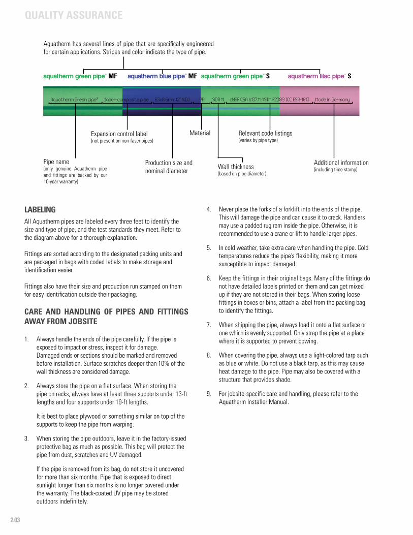
LABELINGAll Aquatherm pipes are labeled every three feet to identify the size and type of pipe, and the test standards they meet. Refer to the diagram above for a thorough explanation.
Fittings are sorted according to the designated packing units and are packaged in bags with coded labels to make storage and identification easier.
Fittings also have their size and production run stamped on them for easy identification outside their packaging.
CARE AND HANDLING OF PIPES AND FITTINGS AWAY FROM JOBSITE
1. Always handle the ends of the pipe carefully. If the pipe is exposed to impact or stress, inspect it for damage. Damaged ends or sections should be marked and removed before installation. Surface scratches deeper than 10% of the wall thickness are considered damage.
2. Always store the pipe on a flat surface. When storing the pipe on racks, always have at least three supports under 13-ft lengths and four supports under 19-ft lengths.
It is best to place plywood or something similar on top of the supports to keep the pipe from warping.
3. When storing the pipe outdoors, leave it in the factory-issued protective bag as much as possible. This bag will protect the pipe from dust, scratches and UV damaged.
If the pipe is removed from its bag, do not store it uncovered for more than six months. Pipe that is exposed to direct sunlight longer than six months is no longer covered under the warranty. The black-coated UV pipe may be stored outdoors indefinitely.
4. Never place the forks of a forklift into the ends of the pipe. This will damage the pipe and can cause it to crack. Handlers may use a padded rug ram inside the pipe. Otherwise, it is recommended to use a crane or lift to handle larger pipes.
5. In cold weather, take extra care when handling the pipe. Cold temperatures reduce the pipe’s flexibility, making it more susceptible to impact damaged.
6. Keep the fittings in their original bags. Many of the fittings do not have detailed labels printed on them and can get mixed up if they are not stored in their bags. When storing loose fittings in boxes or bins, attach a label from the packing bag to identify the fittings.
7. When shipping the pipe, always load it onto a flat surface or one which is evenly supported. Only strap the pipe at a place where it is supported to prevent bowing.
8. When covering the pipe, always use a light-colored tarp such as blue or white. Do not use a black tarp, as this may cause heat damage to the pipe. Pipe may also be covered with a structure that provides shade.
9. For jobsite-specific care and handling, please refer to the Aquatherm Installer Manual.
Aquatherm has several lines of pipe that are specifically engineered for certain applications. Stripes and color indicate the type of pipe.
Pipe name(only genuine Aquatherm pipe and fittings are backed by our 10-year warranty)
Expansion control label (not present on non-faser pipes)
Production size and nominal diameter
Material
Wall thickness (based on pipe diameter)
Relevant code listings (varies by pipe type)
Additional information(including time stamp)
aquatherm green pipe® MF aquatherm blue pipe® MF aquatherm green pipe® S aquatherm lilac pipe® S
Aquatherm Green pipe® faser-composite pipe 63x8.6mm (2” N.D.) PP SDR 11 cNSF CSA b137.11 ASTM F2389 ICC ESR-1613 Made in Germany
2.04
QUALITY ASSURANCE
• NSF Standard 61 (C.HOT 180 °F/82 °C) Suitable for potable water
• NSF Standard 14 Meets piping performance requirements
• NSF Standard 51 Suitable for food processing up to 212 °F (100 °C)
• CFIA #A508 Canadian Food Inspection Agency approval #A508
• ICC ESR-1613 / PMG Listing 1014Polypropylene pipe and fittings meet or exceed North American standards
• DIN EN ISO 9001 Quality management systems: requirements
• IPC 2009 Sec. 605 Water distribution and water service
• IMC 2009 Chapter 12 Hydronic piping
• IRC 2009 Chapter 21 & 26 Hydronic piping and plumbing
• UMC 2009 Chapter 12 Hydronic piping
• UPC 2012 Chapter 6 Water distribution and building supply
• IAPMO File M-6022 Mechanical
• IAPMO File 5053 Plumbing
• ASTM F2389Standard specification for pressure rated polypropylene (PP) piping systems
• CSA B137.11Polypropylene (PP and PP-RCT) pipe and fittings for pressure applications
• CSA B214Polypropylene (PP and PP-RCT) pipe and fittings for hydronic applications
• BNQ 3660-950Safety of products and materials in contact with drinking water
• ISO 15874Plastic pipe system for hot and cold water installation: polypropylene
• ASTM F2023Standard test method for evaluating the oxidative resistance of plastic piping to hot chlorinated water
• ASTM D 635Standard test method for rate of burning and/or extent and time of burning of plastics in a horizontal position
• FM 1635 For wet pipe automatic sprinkler systems in light-hazard occupancies
• NFPA 13, 13D and 13RStandard for the installation of sprinkler systems in one- /two-family dwellings and manufactured homes
• DIN EN ISO 14001 Standard for environmental management
• ASME B31.3 Standard for process piping
• ASME B31.9Standard for building services piping
• CCMC 14006-RCanadian Construction Materials Centre
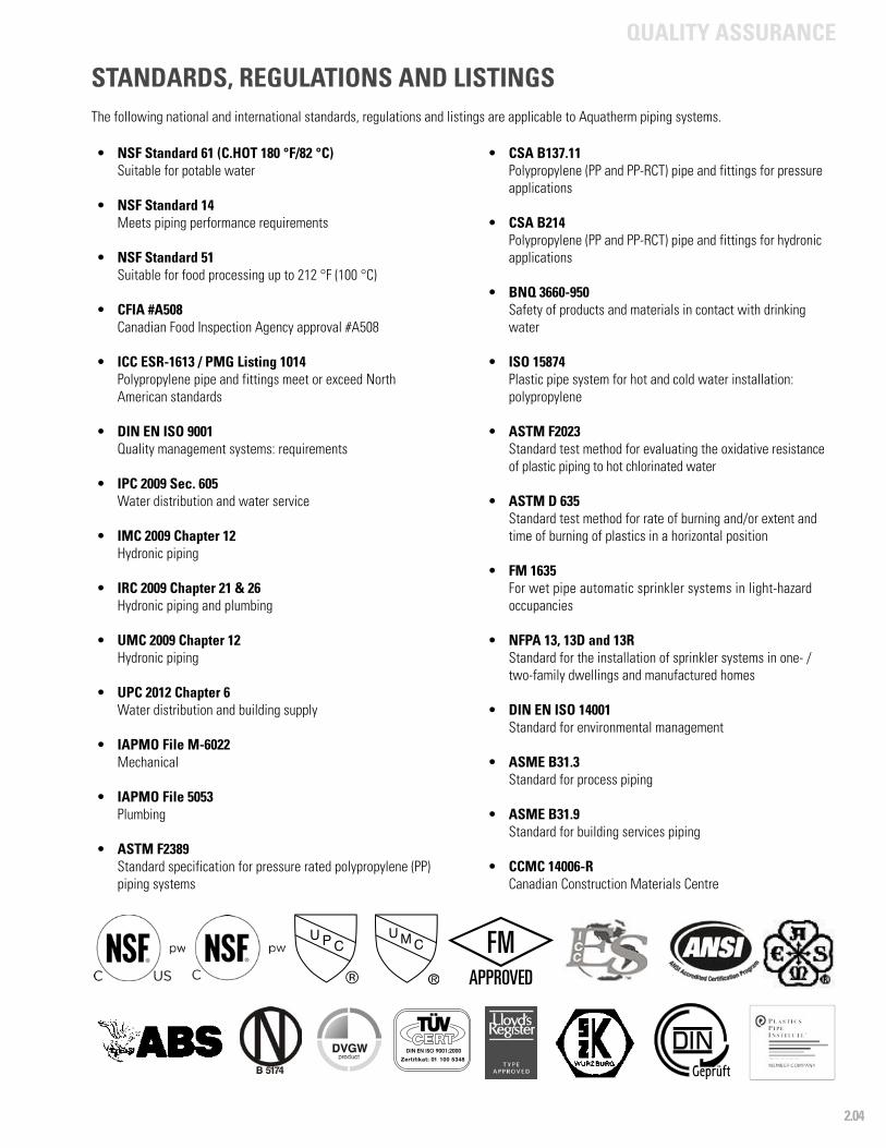
STANDARDS, REGULATIONS AND LISTINGSThe following national and international standards, regulations and listings are applicable to Aquatherm piping systems.

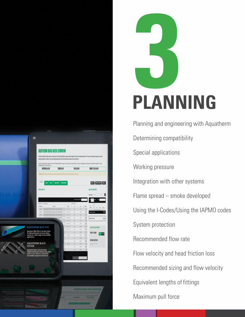
PLANNING
Planning and engineering with Aquatherm
Determining compatibility
Special applications
Working pressure
Integration with other systems
Flame spread – smoke developed
Using the I-Codes/Using the IAPMO codes
System protection
Recommended flow rate
Flow velocity and head friction loss
Recommended sizing and flow velocity
Equivalent lengths of fittings
Maximum pull force
3PLANNING

PLANNING
3.01
PLANNING AND ENGINEERING WITH AQUATHERMWith unique advantages over both metal and other plastics, Aquatherm piping systems offer new possibilities for design and application.
By combining revolutionary strength and longevity with industry-leading purity and neutrality, Aquatherm manufactures piping systems that can truly address all possible concerns for potable, food-grade, hydronic, chemical and industrial applications.
When designing with Aquatherm piping systems, it is important to be aware of their unique features such as multi-layer, faser-composite (MF), which provides expansion control, the fusion connections, the impact and chemical resistance and the sound insulation.
The natural R-value and reduced friction factors are especially important because they reduce the amount of energy needed for the system to perform. With careful planning and engineering, it is possible to exceed existing performance standards and maximize a system’s efficiency.
Be sure to verify all calculations before installing an Aquatherm piping system. The sizing and insulation recommendations given in this catalog are intended for easy reference and are not a substitute for actual engineering.
Aquatherm also publishes Technical Bulletins that provide further information on specific applications, product use, installation and testing. These Technical Bulletins are available at: www.aquatherm.com/technical-bulletins. Additional requirements for installation are given in the Aquatherm Installer Manual, which can be found at: www.aquatherm.com/aquatherm-installer-manual.
DETERMINING COMPATIBILITYThe first step to designing with Aquatherm is to verify that PP-R and/or PP-RP (RCT) is an acceptable material choice for a particular application.
Aquatherm pipes are suited to a wide variety of applications and generally perform without the problems that plague other systems.
However, PP-R and PP-RP (RCT) still have some chemical, pressure and temperature considerations that need to be addressed in order to limit the risk of failure.
Operating outside of the safety parameters provided by Aquatherm can shorten the life of the pipe. By bringing a system’s intended load in line with the safety parameters given in this chapter, a designer can ensure that the pipes will last for their entire 60-year life span or longer. The easiest way to find out if Aquatherm pipe is suitable for use with a certain chemical is to email [email protected].
Temperature
aquatherm green pipe®
SDR 11 (non-MF)
aquatherm green pipe®
SDR 7.4 (MF)
aquatherm lilac pipe®
SDR 11 (non-MF)
aquatherm blue pipe®
SDR 9 (MF RP)
aquatherm blue pipe®
SDR 11 (MF)
aquatherm blue pipe®
SDR 17.6 (MF)
Permissible working pressure (psi)
50 °F 195 380 195 385 285 160
80 °F 170 320 170 305 220 125
100 °F 135 255 135 255 185 95
120 °F 110 215 110 215 155 80
140 °F 95 180 95 180 130 70
160 °F - 120 - 150 100 45
180 °F - 100 - 125 62 25
200 °F - 45 100 30 15
(Select SDR based on Temp and Pressure Requirements)NON-POTABLEPOTABLE COLD
Available Diameters:
POTABLE HOT NON-POTABLEreclaimed water
20 - 450 mm 20 - 355 mm 20 - 160 mm 32 - 355 mm 20 - 450 mm 125 - 630 mm 1/2” - 18” 1/2” - 10” 1/2” - 6” 1” - 14” 1/2” - 18” 4” - 24”
AQUATHERM SYSTEM SELECTION

PLANNING
3.02
SPECIAL APPLICATIONSDue to their special material properties, Aquatherm pipes and fittings are generally chemical-resistant. However, there are certain applications where PP-R and PP-RP (RCT) may not be acceptable.
Steam systems, water systems with both high temperature and pressure, or systems with high levels of certain aggressive chemicals will likely not be suitable for use with PP-R and PP-RP (RCT). If you are uncertain about a specific application, Aquatherm can perform on-demand testing to determine suitability. To request a test for your project, fill out and submit the special applications form found online at www.aquatherm.com/chemical-compatibility.
In some applications, Aquatherm pipe will not last for a full 10 years, but may still outlast other piping alternatives. These are considered “sub-10” applications and are not covered by the warranty. However, they may still be installed at the end user’s discretion.
The form can also be used to verify compatibility for chemical, high-heat, high-pressure or other non-standard applications.
Transition fittings with brass inserts may not be compatible for all media. Stainless steel inserts are available and may be used in some applications in place of brass. Specialty transtion fittings made entirely of polypropylene are available for some limited applications.
BURIED APPLICATIONSUnlike many other piping materials, PP-R and PP-RP (RCT) are able to absorb the stress caused by expansion within certain limits. The multi-layer, faser-composite (MF) construction helps keep the pipe within these limits for most applications. In cases where the pipe needs to be buried in soil, sand or concrete, PP-R and PP-RP (RCT) is safe, nonleaching and resistant
to crushing or damage. Aquatherm PP-R and PP-RP (RCT) pipe is also suitable for directional boring, if a properly sized pulling head is used. For additional information on buried pipe and maximum pull force for directional boring, see page 3.36 and the Aquatherm Technical Bulletins, www.aquatherm.com/allowable-loading-of-buried-aquatherm-pipe, www.aquatherm.com/direct-burial-aquatherm-pipe, www.aquatherm.com/aquatherm-and-buoyancy. Other bulletins and case studies applicable to the system requirements can be found at www.aquatherm.com/technical-bulletins and www.aquatherm.com/aquatherm-projects.
Buried installations generally do not require additional consideration for the expansion of MF pipes. Resistance to movement from the concrete or backfill will restrict the natural expansion or contraction of the pipe. The expansive forces of PP-R and PP-RP (RCT) are much lower than metal pipes. Aquatherm pipe is safe to use with insulating backfills. Because of the thermal resistance of PP-R and PP-RP (RCT), dry sand may be acceptable as a backfill for insulation purposes. Six inches of dry sand equates to roughly one inch of fiberglass insulation. When penetrating through concrete on an application where the pipe can expand and contract regularly, a shield or protective layer must be used and should be installed per local codes. It is best to anchor the pipe at that location. Please see the Maximum Pull Force section and contact your local representative for more information on buried applications and directional boring.
PLANNINGPLANNING
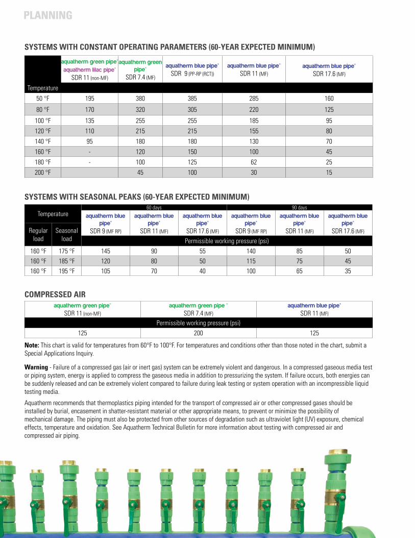
SYSTEMS WITH SEASONAL PEAKS (60-YEAR EXPECTED MINIMUM)
Temperature60 days 90 days
aquatherm blue pipe®
SDR 9 (MF RP)
aquatherm blue pipe®
SDR 11 (MF)
aquatherm blue pipe®
SDR 17.6 (MF)
aquatherm blue pipe®
SDR 9 (MF RP)
aquatherm blue pipe®
SDR 11 (MF)
aquatherm blue pipe®
SDR 17.6 (MF)Regular load
Seasonal load Permissible working pressure (psi)
160 °F 175 °F 145 90 55 140 85 50160 °F 185 °F 120 80 50 115 75 45160 °F 195 °F 105 70 40 100 65 35
aquatherm green pipe®SDR 11 (non-MF)
aquatherm green pipe ® SDR 7.4 (MF)
aquatherm blue pipe® SDR 11 (MF)
Permissible working pressure (psi)125 200 125
COMPRESSED AIR
Warning - Failure of a compressed gas (air or inert gas) system can be extremely violent and dangerous. In a compressed gaseous media test or piping system, energy is applied to compress the gaseous media in addition to pressurizing the system. If failure occurs, both energies can be suddenly released and can be extremely violent compared to failure during leak testing or system operation with an incompressible liquid testing media.
Aquatherm recommends that thermoplastics piping intended for the transport of compressed air or other compressed gases should be installed by burial, encasement in shatter-resistant material or other appropriate means, to prevent or minimize the possibility of mechanical damage. The piping must also be protected from other sources of degradation such as ultraviolet light (UV) exposure, chemical effects, temperature and oxidation. See Aquatherm Technical Bulletin for more information about testing with compressed air and compressed air piping.
Note: This chart is valid for temperatures from 60°F to 100°F. For temperatures and conditions other than those noted in the chart, submit a Special Applications Inquiry.
SYSTEMS WITH CONSTANT OPERATING PARAMETERS (60-YEAR EXPECTED MINIMUM)
Temperature
aquatherm green pipe®aquatherm lilac pipe®
SDR 11 (non-MF)
aquatherm green pipe®
SDR 7.4 (MF)
aquatherm blue pipe® SDR 9 (PP-RP (RCT))
aquatherm blue pipe® SDR 11 (MF)
aquatherm blue pipe® SDR 17.6 (MF)
50 °F 195 380 385 285 160
80 °F 170 320 305 220 125
100 °F 135 255 255 185 95
120 °F 110 215 215 155 80
140 °F 95 180 180 130 70
160 °F - 120 150 100 45
180 °F - 100 125 62 25
200 °F 45 100 30 15
PLANNING
3.04
PLANNING
DOMESTIC HOT WATER RECIRCULATION (DHWR)The Domestic Hot Water Recirculating System includes all portions of the DHW system where the water is being circulated, including supply and return piping and any components other than end-of-the-line fixtures. When there is copper piping used in conjunction with PP-R and PP-RP (RCT) in a DHWR system, care should be taken to ensure the operating conditions will not cause degradation or erosion/corrosion of the copper. Aquatherm recommends following the Copper Development Association guidelines (CDA Publication A4015-14/16: The Copper Tube handbook – www.copper.org) for sizing, temperature and flow velocity in copper tubing. This will also help ensure that the copper levels in the water do not approach the regulatory action levels recommended by independent institutions (e.g. U.S. Environmental Protection Agency (EPA), World Health Organization (WHO), Federal Ministry of Justice and Consumer Protection of Germany). Sustained high levels of copper in DHWR piping can damage components within the system, even PP-R and PP-RP (RCT). Damage caused by copper in the water resulting from erosion/corrosion or other degradation of copper components in the DHWR system will void the Aquatherm warranty.
Accordingly, and as mandated by various regulations and codes in DHWR systems, it is considered good design and operational practice to ensure that the maximum HW-temperature within any part of the system/loop does not exceed 60°C (140°F). Some regulations and codes further restrict the temperature at any fixture to a maximum of 50°C (120°F). There are some exceptions to this, such as the process of thermal disinfection in health care facilities where temperatures of 70°C (160°F) or higher can be applied for short periods of time throughout the pipe system.
Importantly, the maximum temperature used must not exceed the rating of the pipe for the operating pressure. (See Aquatherm green pipe catalog – table: permissible working pressure potable/drinking water)
According to some regulations and codes, flow rates in a DHWR system should not exceed 0.5 m/s (1.5 ft/sec) anywhere in the system, except in some special cases where velocities up to 1 m/s (3 ft/sec)
INTEGRATION OF OTHER SYSTEMS OR COMPONENTS WITH AQUATHERM PIPING FOR PRESSURE PIPE APPLICATIONS
When integrating Aquatherm piping systems with other systems or components not made of PP-R and PP-RP (RCT) (e.g. components not made of PP-R and PP-RP (RCT), like valves, pumps, other piping, check valves, strainers, etc), care must be taken to ensure the operating parameters for PP-R and PP-RP (RCT) won’t damage the other materials or vice versa.
Be aware that even if the Aquatherm pipe is compatible with the fluid being transported, other materials in the system may not be. All parts of the system must be verified as compatible with the medium being carried before installing them. And, while Aquatherm pipe does not require treatment to protect it from corrosion, metals (ferrous and non-ferrous) in the system may be susceptible to corrosion.
Do not mix Aquatherm pipe with other piping systems in conditions that will cause the other system or components to fail.
are needed to achieve proper flow temperature. The CDA Publication A4015-14/16 – The Copper Tube handbook – limits the velocity in DHWR system to similar rates.
When re-piping an existing DHWR-system originally installed in copper tubing, ensure all possible copper is replaced. If some copper remains as part of the system, strictly follow the rules and guidelines of the Copper Development Association (CDA Publication A4015-14/16: The Copper Tube Handbook) regarding flow rates and water conditions. Small amounts of copper or brass in valves and other equipment will generally not cause an issue. If the copper fails, it may degrade o-rings, gaskets, PP-R and PP-RP (RCT) and other components, shortening their service life.
When adding PP-R and PP-RP (RCT) to an existing copper system in a DHWR-application, the level of copper in the water should be tested. These levels should not exceed 0.1 mg/L (ppm). Higher levels of total copper indicate that the copper pipe is corroding/eroding due to system and/or water conditions.
To hydraulically balance a DHWR-system and ensure the required flow rate for each area of the building, it is necessary to install hydraulic-balancing-valves in every circulating loop throughout the complete system. This also maintains the flow velocity in the smaller return piping at or below the manufacturer‘s or CDA‘s recommendations. In addition to sizing the piping and pumps to the correct flow velocity, care must also be taken to avoid water hammer and excessive surge pressures. Pump systems operating with on/off cycling, or pumps over-sized for the piping, can create high pressure and fatigue the piping material. The pump total dynamic head (TDH) must also be matched to the flow requirements, piping layout and operating conditions to avoid cavitation for all components throughout the system. Cavitation can lead to excessive system noise and more importantly, can result in the erosion and degradation of the pipe surface and other components. Properly sized variable-speed (VFD) constant pressure pumping systems and pressure-sustaining valves can alleviate these issues. The pumps should be sized to operate at maximum efficiency with the lowest energy usage for the required flow rate.
The issues described here are only of concern in DHWR-systems. For domestic cold water (DCW) and mechanical (heating-cooling) systems no additional requirements or actions are necessary. In some situations, the DHWR system is also used to provide hot water to the mechanical heating system. Additional consideration and care must be given for this type of combined system, as the mechanical components may not be compatible with the more aggressive water conditions and flow velocity limitations of DHWR systems, and these components may be not suitable for potable water contact.
PLANNING
3.05
FLAME- AND SMOKE-RATED OPTIONSFor applications where the code requires the pipe to meet an FSI of 25 and SDI of 50, Aquatherm recommends one of the following solutions:
1. Aquatherm Advanced is a listed solution for meeting the E84 and S-102.2 ratings. Aquatherm Advanced is a combination of Aquatherm pipe and a fire-rated insulation. Aquatherm Advanced may also provide sufficient insulation value for hot and cold applications, but the thermal values are dependent on the manufacturer of the insulation. An Aquatherm Advanced system does not require the fittings to be insulated for fire-rating purposes, but the fittings may still need to be insulated to prevent condensation.
2. Encasing the pipe inside of any insulation that meets the 25/50 flame spread and smoke development requirements (see page 3.6). This solution requires that the fittings be insulated as well and is subject to adoption of the relevant IMC and UMC codes as well as the local authority having jurisdiction. Alternatively, the pipe can be enclosed in a fire-rated chase.
3. Avoid using a ceiling return air plenum. Using ducted or dedicated outdoor air eliminates the health and safety risks introduced by a return air plenum. It also eliminates the need for a large number of fire-retardant chemicals within the building. Pipe that is not inside a return air plenum generally does not need to meet flame spread and smoke development requirements.
With these options, the engineer should be able to comply with all local codes involving flame spread and smoke development. However, it is important to confirm with local officials that the measures being taken are acceptable before beginning the installation.
FLAME SPREAD / SMOKE DEVELOPEDAquatherm piping systems do not produce toxic by-products during combustion. In a fully developed fire, fusiolen® PP-R and PP-RP (RCT) will only produce CO2 and H2O gas. In an under-developed fire, trace amounts of CO can be produced, but this is common in all combustible materials, including wood and paper.
Many building codes do not consider the toxicity of the smoke produced but focus only on the volume and opacity of the smoke. Therefore, it is important to install only pipe that meets local code requirements. These codes generally reference ASTM E84 in the United States and CAN/ULC S-102.2 in Canada and require that the installed pipe have a Flame Spread Index of 25 or less and Smoke Developed Index of 50 or less.
According to the IMC and UMC building codes, materials that are completely enclosed in a fire-rated material, such as pipe insulation, are considered fire rated as well, because they are not technically exposed in the plenum.
PLANNING
3.06
USING THE I-CODESUnder the IMC, materials exposed within plenums are required to meet the ASTM E 84 test for flame spread and smoke development. As given in the 2006 edition:
602.2.1 Materials exposed within plenumsExcept as required by Sections 602.2.1.1 through 602.2.1.5, materials within plenums shall be noncombustible or shall have a flame spread index of not more than 25 and a smoke-developed index of not more than 50 when tested in accordance with ASTM E 84.
Exceptions:
5. Combustible materials enclosed in noncombustible raceways or enclosures, approved gypsum board assemblies or enclosed in materials listed and labeled for such application.
Exception 5 excluded materials that were enclosed within noncombustible (or otherwise approved) materials, as the enclosed materials are technically concealed, rather than exposed. This exception was further detailed in the 2012 edition, making the intent of the previous editions clear:
602.2.1 Materials exposed within plenumsExcept as required by Sections 602.2.1.1 through 602.2.1.5, materials within plenums shall be noncombustible or shall have a flame spread index of not more than 25 and a smoke-developed index of not more than 50 when tested in accordance with ASTM E 84 or UL 723.
Exceptions:
5. Combustible materials fully enclosed within one of the following:5.1 Continuous noncombustible raceways or enclosures5.2 Approved gypsym board assemblies5.3 Materials listed and labeled for installation within a plenum.
Under the IMC, Aquatherm pipe may be safely installed in a plenum if the pipe and fittings are contained within an insulation that meets the ASTM E 84 test requirements. This is due to the fact that pipes enclosed within the insulation are no longer considered exposed inside the plenum. Where insulation is not needed, a plenum-rated wrap will also suffice.
USING THE IAPMO CODES The UMC contains similar requirements to the IMC in regards to plenums. In turn, the exceptions are similar, although the UMC does not offer as detailed of an exception. In the 2009 edition, it reads:
602.2 Combustibles within Ducts or PlenumsMaterials exposed within ducts or plenums shall be noncombustible or shall have a flame spread index not greater than twenty five (25) and a smoke developed index not greater than fifty (50), when tested as a composite product in accordance with one of the following test methods: NFPA 255, Method of Test of Surface Burning Characteristics of Building Materials, ASTM E 84, Surface Burning Characteristics of Building Materials or UL 723, Test for Surface Burning Characteristics of Building Materials except as indicated below.
In this case, materials that are exposed are required to be non-combustible or meet flame spread and smoke developed requirements. Materials that are not exposed within the plenum are therefore excluded. This follows the logic and intent of the IMC.
More recent versions maintain this language, but simplify the associated test methods. In the 2012 edition:
602.2 Combustibles within Ducts or PlenumsMaterials exposed within ducts or plenums shall be noncombustible or shall have a flame spread index not greater than twenty five (25) and a smoke developed index not greater than fifty (50), when tested as a composite product in accordance with ASTM E 84 or UL 723, except as indicated below.
In short, under the UMC, Aquatherm pipe may be safely installed in a plenum as long as the pipe is not exposed to the plenum space. This is easily solved by encasing the pipe and fittings in a plenum-rated insulation. Where insulation is not required, a plenum-rated wrap may be used instead.
OTHER SOLUTIONSIf the plenum-rating options discussed here will not suffice for a particular installation, please contact Aquatherm’s Engineering Support department in Lindon, Utah by phone (801-805-6657) or email ([email protected]).
PLANNING
3.07
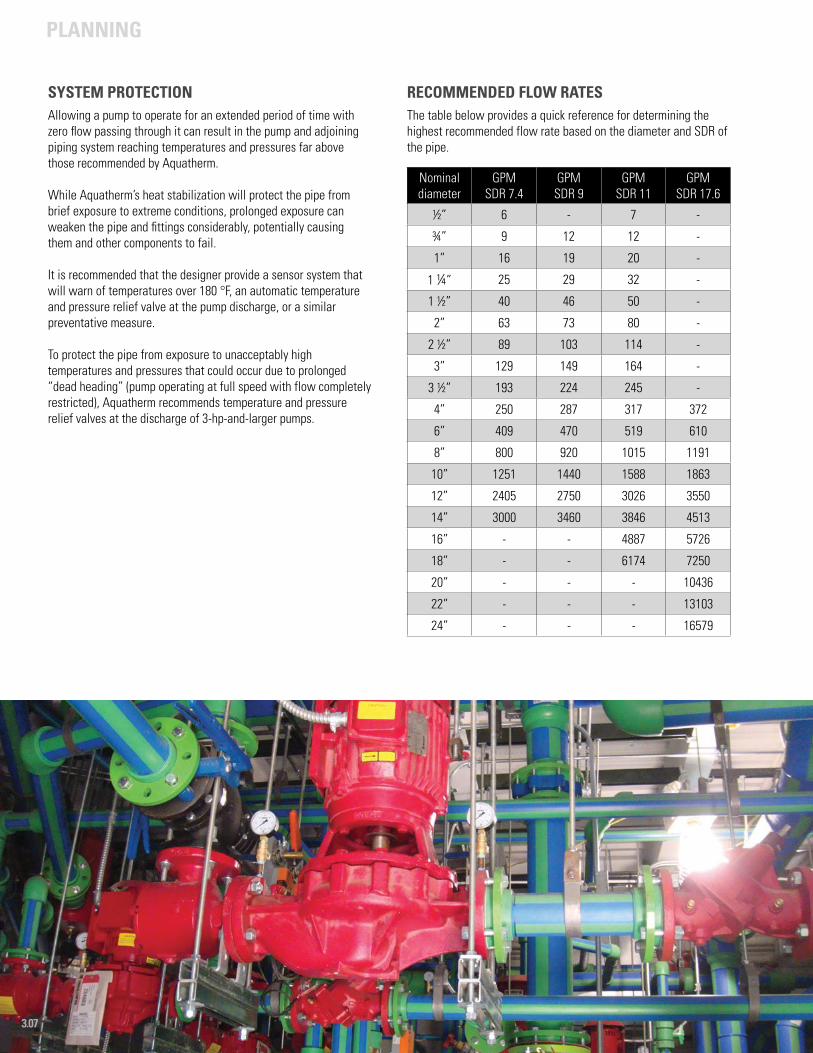
SYSTEM PROTECTIONAllowing a pump to operate for an extended period of time with zero flow passing through it can result in the pump and adjoining piping system reaching temperatures and pressures far above those recommended by Aquatherm.
While Aquatherm’s heat stabilization will protect the pipe from brief exposure to extreme conditions, prolonged exposure can weaken the pipe and fittings considerably, potentially causing them and other components to fail.
It is recommended that the designer provide a sensor system that will warn of temperatures over 180 °F, an automatic temperature and pressure relief valve at the pump discharge, or a similar preventative measure.
To protect the pipe from exposure to unacceptably high temperatures and pressures that could occur due to prolonged “dead heading” (pump operating at full speed with flow completely restricted), Aquatherm recommends temperature and pressure relief valves at the discharge of 3-hp-and-larger pumps.
RECOMMENDED FLOW RATESThe table below provides a quick reference for determining the highest recommended flow rate based on the diameter and SDR of the pipe.
Nominal diameter
GPMSDR 7.4
GPMSDR 9
GPMSDR 11
GPMSDR 17.6
½” 6 - 7 -
¾” 9 12 12 -
1” 16 19 20 -
1 ¼” 25 29 32 -
1 ½” 40 46 50 -
2” 63 73 80 -
2 ½” 89 103 114 -
3” 129 149 164 -
3 ½” 193 224 245 -
4” 250 287 317 372
6” 409 470 519 610
8” 800 920 1015 1191
10” 1251 1440 1588 1863
12” 2405 2750 3026 3550
14” 3000 3460 3846 4513
16” - - 4887 5726
18” - - 6174 7250
20” - - - 10436
22” - - - 13103
24” - - - 16579
PLANNING
3.08
RECOMMENDED SIZING AND FLOW VELOCITYThe following table provides the recommended design velocity for the range of pipe sizes.
In certain cases velocities higher than the above recommended values can be used. Some codes allow up to 10 ft/sec (3.05 m/sec) for plumbing if the manufacturer recommends it. There is also the possibility of the codes allowing up to 12 ft/sec (3.66 m/sec) for plastic piping.
Aquatherm has allowed engineers to design with velocities as high as 15 – 20 ft/sec (4.57 – 6.10 m/sec) depending on the job and design. This allowance comes with a caveat to ensure that there will not be any quick-acting valves or other sources of surge pressures in the system. So in some cases, it is permissible to design to the higher velocities for the pipe material, but the system may not be able to handle the higher velocities in terms of pressure surges, water hammer or noise issues.
One of the advantages to designing with higher velocities is overcoming the decreased volumetric flow rates (gpm) that can result from using a lower velocity with a smaller internal diameter of some Aquatherm pipe dimensions compared to copper and steel.
Aquatherm recommends not exceeding the flow velocities shown in the following table without first consulting Aquatherm.
The tables on the following pages give the head loss and flow rates of the pipe based on the pipe size and the desired gpm. Reducing head loss on the critical leg of the system can allow for downsizing on other sections of pipe. Lower velocities may be necessary depending on the aggressiveness of the fluid and operating conditions.
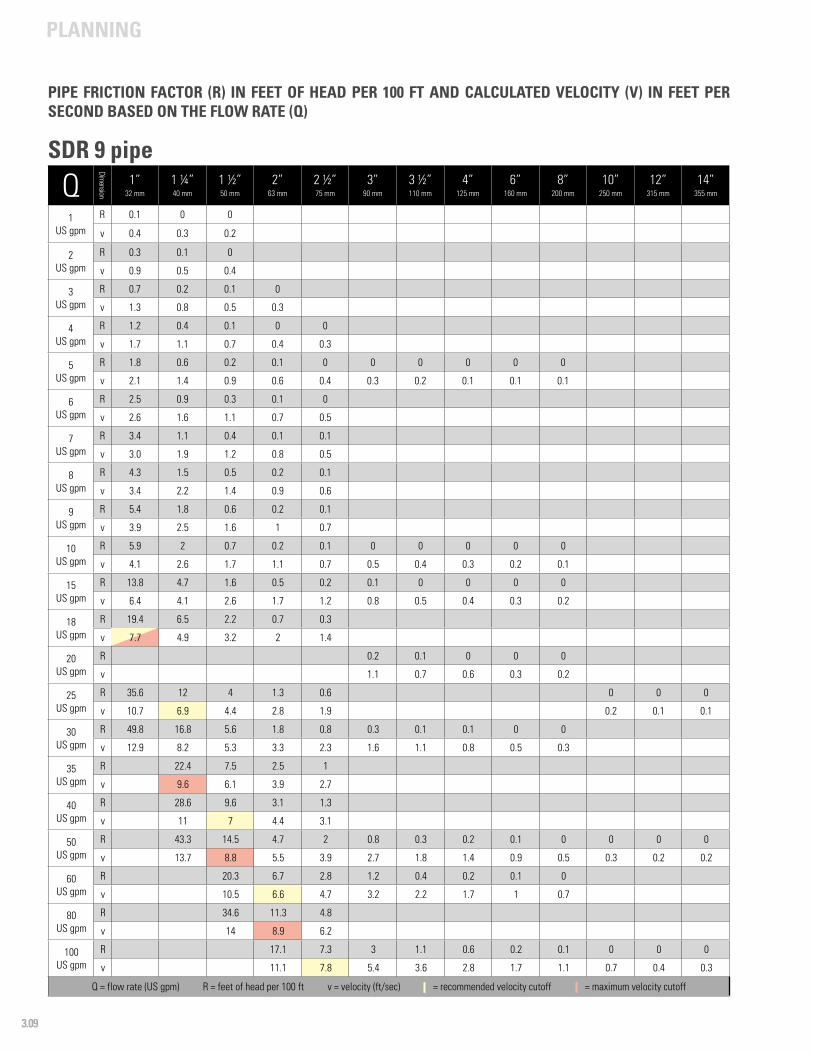
The yellow cells in each column indicate where flow rates begin to exceed the recommended velocities for a particular size while the red cells denote where flow rates exceed the maximum velocities.
FLOW VELOCITY AND HEAD (FRICTION) LOSSThe head loss (friction pressure loss) due to the flow of water through the Aquatherm PP-R or PP-RP (RCT) piping is given in the following tables. The water velocity is also provided. These values are calculated from the equations below. The Hazen-Williams formula is widely used in water piping applications, but it does not account for differences in fluid viscosity (different fluids) and fluid temperature. Consult your Aquatherm representative for information on other applications such as chemical process piping or compressed gases.
Hazen-Williams formula for pressure loss (psi/100 ft of pipe):
Where: PL = pressure loss, psi /100 ft of pipeQ = flow rate, gpmdi = inside diameter of pipe, inchesC = flow coefficient = 150 for PP-R or PP-RP (RCT) piping
Conversion to head loss (ft of head loss per 100 ft of pipe):
HL = 2.31(PL)
Where: HL = head loss, ft / 100 ft of pipe
Calculation of flow velocity:
Where: v = flow velocity, ft/sec
PIPE SIZING BY HEAD LOSSThis section includes charts on the head loss of SDR 7.4, SDR 9, SDR 11, and SDR 17.6 systems as well as the estimated flow speed based on the chosen flow rate. It is important to note the differences between the standard dimensional ratios as the actual IDs for each vary slightly.
Aquatherm pipes can safely run at higher flow speeds in certain sizes. A complete breakdown of head loss by pipe size and velocity can be found in the charts on the following pages.
Pipe size Recommended design velocity
½” (20mm) – 6” (160 mm) 8 ft/sec (2.44 m/sec)
8” (200mm) – 10” (250 mm) 10 ft/sec (3.05 m/sec)
12” (315 mm) – 18” (450 mm) 12 ft/sec (3.66 m/sec)
20” (500 mm) – 24” (630 mm) 14 ft/sec (4.27 m/sec)
Pipe size Maximum design velocity
½” (20mm) – 8” (200 mm) 10 ft/sec (3.05 m/sec)
10” (250 mm) – 12” (315 mm) 12 ft/sec (3.66 m/sec)
14” (355 mm) – 24” (630 mm) 14 ft/sec (4.27 m/sec)
PLANNING
3.09
Q
Dimension
1”32 mm
1 ¼”40 mm
1 ½”50 mm
2”63 mm
2 ½”75 mm
3”90 mm
3 ½”110 mm
4”125 mm
6”160 mm
8”200 mm
10”250 mm
12”315 mm
14”355 mm
1US gpm
R 0.1 0 0
v 0.4 0.3 0.2
2US gpm
R 0.3 0.1 0
v 0.9 0.5 0.4
3 US gpm
R 0.7 0.2 0.1 0
v 1.3 0.8 0.5 0.3
4US gpm
R 1.2 0.4 0.1 0 0
v 1.7 1.1 0.7 0.4 0.3
5US gpm
R 1.8 0.6 0.2 0.1 0 0 0 0 0 0
v 2.1 1.4 0.9 0.6 0.4 0.3 0.2 0.1 0.1 0.1
6US gpm
R 2.5 0.9 0.3 0.1 0
v 2.6 1.6 1.1 0.7 0.5
7US gpm
R 3.4 1.1 0.4 0.1 0.1
v 3.0 1.9 1.2 0.8 0.5
8US gpm
R 4.3 1.5 0.5 0.2 0.1
v 3.4 2.2 1.4 0.9 0.6
9US gpm
R 5.4 1.8 0.6 0.2 0.1
v 3.9 2.5 1.6 1 0.7
10US gpm
R 5.9 2 0.7 0.2 0.1 0 0 0 0 0
v 4.1 2.6 1.7 1.1 0.7 0.5 0.4 0.3 0.2 0.1
15US gpm
R 13.8 4.7 1.6 0.5 0.2 0.1 0 0 0 0
v 6.4 4.1 2.6 1.7 1.2 0.8 0.5 0.4 0.3 0.2
18US gpm
R 19.4 6.5 2.2 0.7 0.3
v 7.7 4.9 3.2 2 1.4
20US gpm
R 0.2 0.1 0 0 0
v 1.1 0.7 0.6 0.3 0.2
25US gpm
R 35.6 12 4 1.3 0.6 0 0 0
v 10.7 6.9 4.4 2.8 1.9 0.2 0.1 0.1
30US gpm
R 49.8 16.8 5.6 1.8 0.8 0.3 0.1 0.1 0 0
v 12.9 8.2 5.3 3.3 2.3 1.6 1.1 0.8 0.5 0.3
35US gpm
R 22.4 7.5 2.5 1
v 9.6 6.1 3.9 2.7
40US gpm
R 28.6 9.6 3.1 1.3
v 11 7 4.4 3.1
50US gpm
R 43.3 14.5 4.7 2 0.8 0.3 0.2 0.1 0 0 0 0
v 13.7 8.8 5.5 3.9 2.7 1.8 1.4 0.9 0.5 0.3 0.2 0.2
60US gpm
R 20.3 6.7 2.8 1.2 0.4 0.2 0.1 0
v 10.5 6.6 4.7 3.2 2.2 1.7 1 0.7
80US gpm
R 34.6 11.3 4.8
v 14 8.9 6.2
100US gpm
R 17.1 7.3 3 1.1 0.6 0.2 0.1 0 0 0
v 11.1 7.8 5.4 3.6 2.8 1.7 1.1 0.7 0.4 0.3
Q = flow rate (US gpm) R = feet of head per 100 ft v = velocity (ft/sec) - = recommended velocity cutoff - = maximum velocity cutoff
PIPE FRICTION FACTOR (R) IN FEET OF HEAD PER 100 FT AND CALCULATED VELOCITY (V) IN FEET PER SECOND BASED ON THE FLOW RATE (Q)
SDR 9 pipe

PLANNING
3.10
Q
Dimension
1”32 mm
1 ¼”40 mm
1 ½”50 mm
2”63 mm
2 ½”75 mm
3”90 mm
3 ½”110 mm
4”125 mm
6”160 mm
8”200 mm
10”250 mm
12”315 mm
14”355 mm
110US gpm
R 3.6 1.3 0.7 0.2 0.1
v 6 4 3.1 1.9 1.2
120US gpm
R 24 10.2
v 13.3 9.3
150US gpm
R 6.3 2.4 1.3 0.4 0.1 0 0 0
v 8.1 5.4 4.2 2.6 1.6 1 0.7 0.5
175US gpm
R 3.2 1.7 0.5 0.2
v 6.3 4.9 3 1.9
200US gpm
R 4 2.2 0.7 0.2 0.1 0 0
v 7.2 5.6 3.4 2.2 1.4 0.9 0.7
225US gpm
R 5 2.7 0.8 0.3
v 8.1 6.3 3.8 2.5
250US gpm
R 0.1 0 0
v 1.7 1.1 0.9
275US gpm
R 3.9 1.2 0.4
v 7.7 4.7 3
300US gpm
R 4.6 1.4 0.5 0.2 0.1 0
v 8.4 5.1 3.3 2.1 1.36 1
325US gpm
R 0.2 0.1 0
v 2.3 1.4 1.1
350US gpm
R 1.8 0.6 0.2 0.1 0
v 6 3.8 2.4 1.5 1.2
450US gpm
R 2.9 1
v 7.7 4.9
500US gpm
R 0.4 0.1 0.1
v 3.5 2.2 1.7
1000US gpm
R 1.5 0.5 0.3
v 7 4.4 3.5
1500US gpm
R 3.1 1 0.6
v 10.5 6.6 5.2
2000US gpm
R 1.7 1
v 8.8 6.9
2500US gpm
R 2.6 1.4
v 11 8.7
3000US gpm
R 2
v 10.4
Q = flow rate (US gpm) R = feet of head per 100 ft v = velocity (ft/sec) - = recommended velocity cutoff - = maximum velocity cutoff
SDR 9 pipe
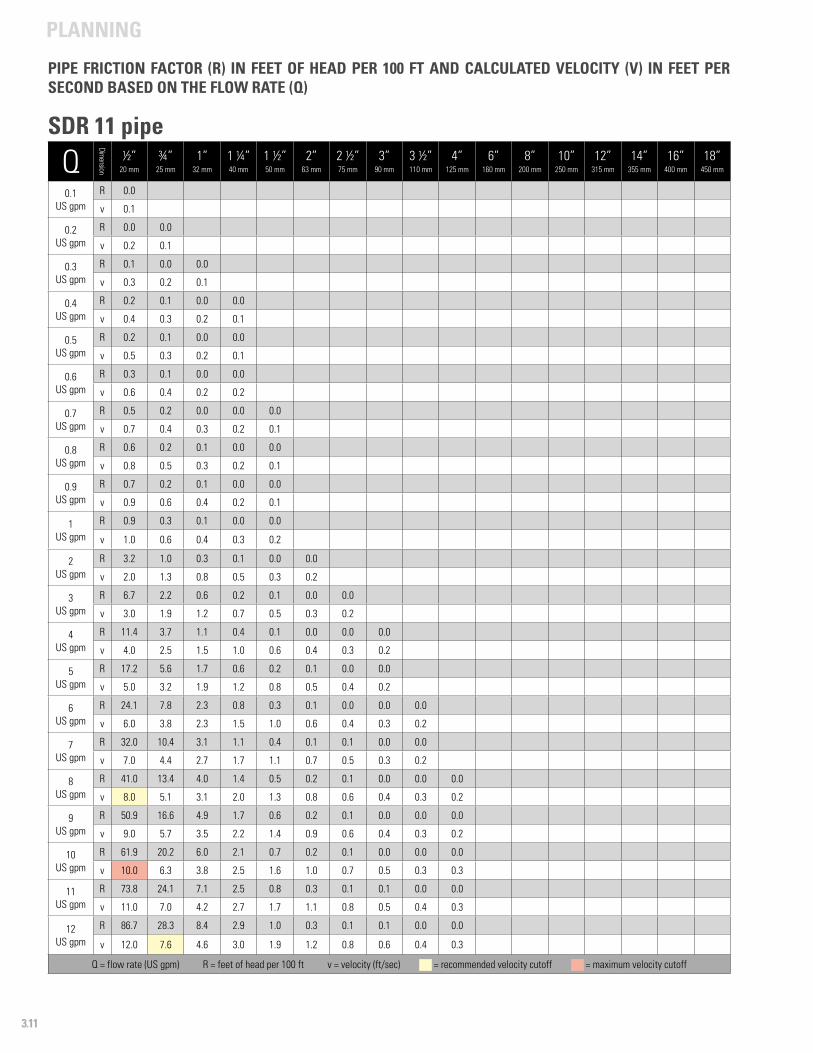
PLANNING
3.11
Q
Dimension
½”20 mm
¾”25 mm
1”32 mm
1 ¼”40 mm
1 ½”50 mm
2”63 mm
2 ½”75 mm
3”90 mm
3 ½”110 mm
4”125 mm
6”160 mm
8”200 mm
10”250 mm
12”315 mm
14”355 mm
16”400 mm
18”450 mm
0.1US gpm
R 0.0
v 0.1
0.2US gpm
R 0.0 0.0
v 0.2 0.1
0.3 US gpm
R 0.1 0.0 0.0
v 0.3 0.2 0.1
0.4 US gpm
R 0.2 0.1 0.0 0.0
v 0.4 0.3 0.2 0.1
0.5US gpm
R 0.2 0.1 0.0 0.0
v 0.5 0.3 0.2 0.1
0.6US gpm
R 0.3 0.1 0.0 0.0
v 0.6 0.4 0.2 0.2
0.7US gpm
R 0.5 0.2 0.0 0.0 0.0
v 0.7 0.4 0.3 0.2 0.1
0.8US gpm
R 0.6 0.2 0.1 0.0 0.0
v 0.8 0.5 0.3 0.2 0.1
0.9US gpm
R 0.7 0.2 0.1 0.0 0.0
v 0.9 0.6 0.4 0.2 0.1
1US gpm
R 0.9 0.3 0.1 0.0 0.0
v 1.0 0.6 0.4 0.3 0.2
2US gpm
R 3.2 1.0 0.3 0.1 0.0 0.0
v 2.0 1.3 0.8 0.5 0.3 0.2
3 US gpm
R 6.7 2.2 0.6 0.2 0.1 0.0 0.0
v 3.0 1.9 1.2 0.7 0.5 0.3 0.2
4US gpm
R 11.4 3.7 1.1 0.4 0.1 0.0 0.0 0.0
v 4.0 2.5 1.5 1.0 0.6 0.4 0.3 0.2
5US gpm
R 17.2 5.6 1.7 0.6 0.2 0.1 0.0 0.0
v 5.0 3.2 1.9 1.2 0.8 0.5 0.4 0.2
6US gpm
R 24.1 7.8 2.3 0.8 0.3 0.1 0.0 0.0 0.0
v 6.0 3.8 2.3 1.5 1.0 0.6 0.4 0.3 0.2
7US gpm
R 32.0 10.4 3.1 1.1 0.4 0.1 0.1 0.0 0.0
v 7.0 4.4 2.7 1.7 1.1 0.7 0.5 0.3 0.2
8US gpm
R 41.0 13.4 4.0 1.4 0.5 0.2 0.1 0.0 0.0 0.0
v 8.0 5.1 3.1 2.0 1.3 0.8 0.6 0.4 0.3 0.2
9US gpm
R 50.9 16.6 4.9 1.7 0.6 0.2 0.1 0.0 0.0 0.0
v 9.0 5.7 3.5 2.2 1.4 0.9 0.6 0.4 0.3 0.2
10US gpm
R 61.9 20.2 6.0 2.1 0.7 0.2 0.1 0.0 0.0 0.0
v 10.0 6.3 3.8 2.5 1.6 1.0 0.7 0.5 0.3 0.3
11US gpm
R 73.8 24.1 7.1 2.5 0.8 0.3 0.1 0.1 0.0 0.0
v 11.0 7.0 4.2 2.7 1.7 1.1 0.8 0.5 0.4 0.3
12US gpm
R 86.7 28.3 8.4 2.9 1.0 0.3 0.1 0.1 0.0 0.0
v 12.0 7.6 4.6 3.0 1.9 1.2 0.8 0.6 0.4 0.3
Q = flow rate (US gpm) R = feet of head per 100 ft v = velocity (ft/sec) - = recommended velocity cutoff - = maximum velocity cutoff
PIPE FRICTION FACTOR (R) IN FEET OF HEAD PER 100 FT AND CALCULATED VELOCITY (V) IN FEET PER SECOND BASED ON THE FLOW RATE (Q)
SDR 11 pipe
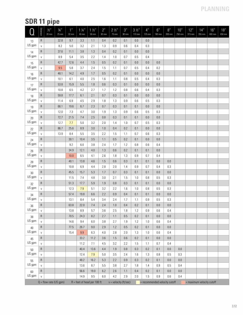
PLANNING
3.12
Q
Dimension
½”20 mm
¾”25 mm
1”32 mm
1 ¼”40 mm
1 ½”50 mm
2”63 mm
2 ½”75 mm
3”90 mm
3 ½”110 mm
4”125 mm
6”160 mm
8”200 mm
10”250 mm
12”315 mm
14”355 mm
16”400 mm
18”450 mm
13US gpm
R 32.8 9.7 3.3 1.1 0.4 0.2 0.1 0.0 0.0
v 8.2 5.0 3.2 2.1 1.3 0.9 0.6 0.4 0.3
14 US gpm
R 37.6 11.1 3.8 1.3 0.4 0.2 0.1 0.0 0.0
v 8.9 5.4 3.5 2.2 1.4 1.0 0.7 0.5 0.4
15US gpm
R 42.7 12.6 4.4 1.5 0.5 0.2 0.1 0.0 0.0 0.0
v 9.5 5.8 3.7 2.4 1.5 1.1 0.7 0.5 0.4 0.2
16US gpm
R 48.1 14.2 4.9 1.7 0.5 0.2 0.1 0.0 0.0 0.0
v 10.1 6.1 4.0 2.5 1.6 1.1 0.8 0.5 0.4 0.3
17US gpm
R 53.8 15.9 5.5 1.8 0.6 0.3 0.1 0.0 0.0 0.0
v 10.8 6.5 4.2 2.7 1.7 1.2 0.8 0.6 0.4 0.3
18US gpm
R 59.8 17.7 6.1 2.1 0.7 0.3 0.1 0.0 0.0 0.0
v 11.4 6.9 4.5 2.9 1.8 1.3 0.9 0.6 0.5 0.3
19US gpm
R 66.1 19.6 6.7 2.3 0.7 0.3 0.1 0.1 0.0 0.0
v 12.0 7.3 4.7 3.0 1.9 1.3 0.9 0.6 0.5 0.3
20US gpm
R 72.7 21.5 7.4 2.5 0.8 0.3 0.1 0.1 0.0 0.0
v 12.7 7.7 5.0 3.2 2.0 1.4 1.0 0.7 0.5 0.3
22US gpm
R 86.7 25.6 8.9 3.0 1.0 0.4 0.2 0.1 0.0 0.0
v 13.9 8.4 5.5 3.5 2.2 1.5 1.1 0.7 0.6 0.3
24US gpm
R 30.1 10.4 3.5 1.1 0.5 0.2 0.1 0.0 0.0
v 9.2 6.0 3.8 2.4 1.7 1.2 0.8 0.6 0.4
26US gpm
R 34.9 12.1 4.0 1.3 0.6 0.2 0.1 0.1 0.0
v 10.0 6.5 4.1 2.6 1.8 1.3 0.9 0.7 0.4
28US gpm
R 40.1 13.8 4.6 1.5 0.6 0.3 0.1 0.1 0.0 0.0
v 10.8 6.9 4.4 2.8 2.0 1.4 0.9 0.7 0.4 0.3
30US gpm
R 45.5 15.7 5.3 1.7 0.7 0.3 0.1 0.1 0.0 0.0
v 11.5 7.4 4.8 3.0 2.1 1.5 1.0 0.8 0.5 0.3
32US gpm
R 51.3 17.7 5.9 1.9 0.8 0.3 0.1 0.1 0.0 0.0
v 12.3 7.9 5.1 3.2 2.2 1.6 1.0 0.8 0.5 0.3
34US gpm
R 57.4 19.8 6.6 2.2 0.9 0.4 0.1 0.1 0.0 0.0
v 13.1 8.4 5.4 3.4 2.4 1.7 1.1 0.9 0.5 0.3
36US gpm
R 63.8 22.0 7.4 2.4 1.0 0.4 0.2 0.1 0.0 0.0
v 13.8 8.9 5.7 3.6 2.5 1.8 1.2 0.9 0.6 0.4
38US gpm
R 70.5 24.3 8.2 2.7 1.1 0.5 0.2 0.1 0.0 0.0
v 14.6 9.4 6.0 3.8 2.7 1.9 1.2 1.0 0.6 0.4
40US gpm
R 77.5 26.7 9.0 2.9 1.2 0.5 0.2 0.1 0.0 0.0
v 15.4 9.9 6.3 4.0 2.8 2.0 1.3 1.0 0.6 0.4
45US gpm
R 33.2 11.2 3.6 1.5 0.6 0.2 0.1 0.0 0.0
v 11.2 7.1 4.5 3.2 2.2 1.5 1.1 0.7 0.4
50US gpm
R 40.4 13.6 4.4 1.9 0.8 0.3 0.2 0.1 0.0 0.0
v 12.4 7.9 5.0 3.5 2.4 1.6 1.3 0.8 0.5 0.3
55US gpm
R 48.2 16.2 5.3 2.2 0.9 0.3 0.2 0.1 0.0 0.0
v 13.6 8.7 5.5 3.8 2.7 1.8 1.4 0.9 0.5 0.4
60US gpm
R 56.6 19.0 6.2 2.6 1.1 0.4 0.2 0.1 0.0 0.0
v 14.9 9.5 6.0 4.2 2.9 2.0 1.5 0.9 0.6 0.4
Q = flow rate (US gpm) R = feet of head per 100 ft v = velocity (ft/sec) - = recommended velocity cutoff - = maximum velocity cutoff
SDR 11 pipe

PLANNING
3.13
Q
Dimension
½”20 mm
¾”25 mm
1”32 mm
1 ¼”40 mm
1 ½”50 mm
2”63 mm
2 ½”75 mm
3”90 mm
3 ½”110 mm
4”125 mm
6”160 mm
8”200 mm
10”250 mm
12”315 mm
14”355 mm
16”400 mm
18”450 mm
65US gpm
R 22.0 7.2 3.0 1.2 0.5 0.3 0.1 0.0 0.0
v 10.3 6.5 4.5 3.2 2.1 1.6 1.0 0.6 0.4
70US gpm
R 25.2 8.2 3.5 1.4 0.5 0.3 0.1 0.0 0.0
v 11.1 7.0 4.9 3.4 2.3 1.8 1.1 0.7 0.4
75US gpm
R 28.7 9.3 3.9 1.6 0.6 0.3 0.1 0.0 0.0
v 11.9 7.5 5.2 3.7 2.4 1.9 1.2 0.7 0.5
80US gpm
R 32.3 10.5 4.4 1.8 0.7 0.4 0.1 0.0 0.0
v 12.7 8.0 5.6 3.9 2.6 2.0 1.2 0.8 0.5
85US gpm
R 36.2 11.7 4.9 2.0 0.8 0.4 0.1 0.0 0.0
v 13.5 8.5 5.9 4.1 2.8 2.1 1.3 0.8 0.5
90US gpm
R 40.2 13.1 5.5 2.3 0.9 0.5 0.1 0.1 0.0 0.0
v 14.3 9.0 6.3 4.4 2.9 2.3 1.4 0.9 0.6 0.4
95US gpm
R 44.4 14.4 6.1 2.5 0.9 0.5 0.2 0.1 0.0 0.0
v 15.0 9.5 6.6 4.6 3.1 2.4 1.5 0.9 0.6 0.4
100US gpm
R 48.8 15.9 6.7 2.8 1.0 0.6 0.2 0.1 0.0 0.0
v 15.8 10.0 7.0 4.9 3.3 2.5 1.5 1.0 0.6 0.4
110US gpm
R 18.9 8.0 3.3 1.2 0.7 0.2 0.1 0.0 0.0
v 11.0 7.7 5.4 3.6 2.8 1.7 1.1 0.7 0.4
120US gpm
R 22.2 9.4 3.9 1.5 0.8 0.2 0.1 0.0 0.0
v 12.0 8.4 5.8 3.9 3.0 1.9 1.2 0.8 0.5
130US gpm
R 25.8 10.8 4.5 1.7 0.9 0.3 0.1 0.0 0.0
v 13.0 9.1 6.3 4.2 3.3 2.0 1.3 0.8 0.5
140US gpm
R 29.6 12.4 5.1 1.9 1.0 0.3 0.1 0.0 0.0
v 14.0 9.8 6.8 4.6 3.5 2.2 1.4 0.9 0.6
150US gpm
R 33.6 14.1 5.8 2.2 1.2 0.4 0.1 0.0 0.0
v 15.0 10.5 7.3 4.9 3.8 2.3 1.5 0.9 0.6
160US gpm
R 37.8 15.9 6.6 2.5 1.3 0.4 0.1 0.1 0.0
v 16.0 11.2 7.8 5.2 4.0 2.5 1.6 1.0 0.6
170US gpm
R 17.8 7.4 2.8 1.5 0.5 0.2 0.1 0.0
v 11.9 8.3 5.5 4.3 2.6 1.7 1.1 0.7
180US gpm
R 19.8 8.2 3.1 1.7 0.5 0.2 0.1 0.0
v 12.6 8.8 5.9 4.5 2.8 1.8 1.1 0.7
190US gpm
R 21.9 9.1 3.4 1.8 0.6 0.2 0.1 0.0
v 13.3 9.2 6.2 4.8 2.9 1.9 1.2 0.8
200US gpm
R 24.1 10.0 3.7 2.0 0.6 0.2 0.1 0.0
v 14.0 9.7 6.5 5.1 3.1 2.0 1.3 0.8
220US gpm
R 28.7 11.9 4.5 2.4 0.7 0.2 0.1 0.0
v 15.4 10.7 7.2 5.6 3.4 2.2 1.4 0.9
240US gpm
R 13.9 5.2 2.8 0.9 0.3 0.1 0.0
v 11.7 7.8 6.1 3.7 2.4 1.5 1.0
260US gpm
R 16.2 6.1 3.3 1.0 0.3 0.1 0.0
v 12.7 8.5 6.6 4.0 2.6 1.6 1.0
280US gpm
R 18.5 7.0 3.8 1.1 0.4 0.1 0.0
v 13.6 9.1 7.1 4.3 2.8 1.8 1.1
Q = flow rate (US gpm) R = feet of head per 100 ft v = velocity (ft/sec) - = recommended velocity cutoff - = maximum velocity cutoff
SDR 11 pipe
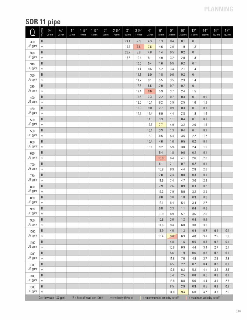
PLANNING
3.14
Q
Dimension
½”20 mm
¾”25 mm
1”32 mm
1 ¼”40 mm
1 ½”50 mm
2”63 mm
2 ½”75 mm
3”90 mm
3 ½”110 mm
4”125 mm
6”160 mm
8”200 mm
10”250 mm
12”315 mm
14”355 mm
16”400 mm
18”450 mm
300US gpm
R 21.1 7.9 4.3 1.3 0.4 0.1 0.1
v 14.6 9.8 7.6 4.6 3.0 1.9 1.2
320US gpm
R 23.7 8.9 4.8 1.4 0.5 0.2 0.1
v 15.6 10.4 8.1 4.9 3.2 2.0 1.3
340US gpm
R 10.0 5.4 1.6 0.5 0.2 0.1
v 11.1 8.6 5.2 3.4 2.1 1.4
360US gpm
R 11.1 6.0 1.8 0.6 0.2 0.1
v 11.7 9.1 5.5 3.5 2.3 1.4
380US gpm
R 12.3 6.6 2.0 0.7 0.2 0.1
v 12.4 9.6 5.9 3.7 2.4 1.5
400US gpm
R 13.5 7.3 2.2 0.7 0.3 0.1 0.0
v 13.0 10.1 6.2 3.9 2.5 1.6 1.2
450US gpm
R 16.8 9.0 2.7 0.9 0.3 0.1 0.1
v 14.6 11.4 6.9 4.4 2.8 1.8 1.4
500US gpm
R 11.0 3.3 1.1 0.4 0.1 0.1
v 12.6 7.7 4.9 3.2 2.0 1.6
550US gpm
R 13.1 3.9 1.3 0.4 0.1 0.1
v 13.9 8.5 5.4 3.5 2.2 1.7
600US gpm
R 15.4 4.6 1.6 0.5 0.2 0.1
v 15.1 9.2 5.9 3.8 2.4 1.9
650US gpm
R 5.4 1.8 0.6 0.2 0.1
v 10.0 6.4 4.1 2.6 2.0
700US gpm
R 6.1 2.1 0.7 0.2 0.1
v 10.8 6.9 4.4 2.8 2.2
750US gpm
R 7.0 2.4 0.8 0.3 0.1
v 11.6 7.4 4.7 3.0 2.3
800US gpm
R 7.9 2.6 0.9 0.3 0.2
v 12.3 7.9 5.0 3.2 2.5
850US gpm
R 8.8 3.0 1.0 0.3 0.2
v 13.1 8.4 5.4 3.4 2.7
900US gpm
R 9.8 3.3 1.1 0.4 0.2
v 13.9 8.9 5.7 3.6 2.8
950US gpm
R 10.8 3.6 1.2 0.4 0.2
v 14.6 9.4 6.0 3.8 3.0
1000US gpm
R 11.9 4.0 1.3 0.4 0.2 0.1 0.1
v 15.4 9.8 6.3 4.0 3.1 2.5 1.9
1100US gpm
R 4.8 1.6 0.5 0.3 0.2 0.1
v 10.8 6.9 4.4 3.4 2.7 2.1
1200US gpm
R 5.6 1.9 0.6 0.3 0.2 0.1
v 11.8 7.6 4.8 3.7 2.9 2.3
1300US gpm
R 6.5 2.2 0.7 0.4 0.2 0.1
v 12.8 8.2 5.2 4.1 3.2 2.5
1400US gpm
R 7.4 2.5 0.8 0.5 0.3 0.1
v 13.8 8.8 5.6 4.4 3.4 2.7
1500US gpm
R 8.5 2.9 0.9 0.5 0.3 0.2
v 14.8 9.4 6.0 4.7 3.7 2.9
Q = flow rate (US gpm) R = feet of head per 100 ft v = velocity (ft/sec) - = recommended velocity cutoff - = maximum velocity cutoff
SDR 11 pipe
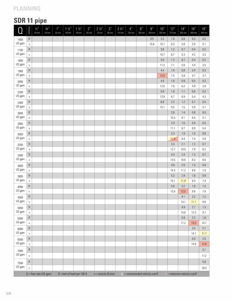
PLANNING
3.15
Q
Dimension
½”20 mm
¾”25 mm
1”32 mm
1 ¼”40 mm
1 ½”50 mm
2”63 mm
2 ½”75 mm
3”90 mm
3 ½”110 mm
4”125 mm
6”160 mm
8”200 mm
10”250 mm
12”315 mm
14”355 mm
16”400 mm
18”450 mm
1600US gpm
R 9.5 3.2 1.0 0.6 0.3 0.2
v 15.8 10.1 6.3 5.0 3.9 3.1
1700US gpm
R 3.6 1.2 0.7 0.4 0.2
v 10.7 6.7 5.3 4.2 3.3
1800US gpm
R 4.0 1.3 0.7 0.4 0.2
v 11.3 7.1 5.6 4.4 3.5
1900US gpm
R 4.4 1.4 0.8 0.4 0.3
v 12.0 7.5 5.9 4.7 3.7
2000US gpm
R 4.9 1.6 0.9 0.5 0.3
v 12.6 7.9 6.2 4.9 3.9
2200US gpm
R 5.8 1.9 1.1 0.6 0.3
v 13.9 8.7 6.9 5.4 4.3
2400US gpm
R 6.8 2.2 1.2 0.7 0.4
v 15.1 9.5 7.5 5.9 4.7
2600US gpm
R 2.6 1.4 0.8 0.5
v 10.3 8.1 6.4 5.1
2800US gpm
R 2.9 1.6 0.9 0.5
v 11.1 8.7 6.9 5.4
3000US gpm
R 3.3 1.9 1.0 0.6
v 11.9 9.4 7.4 5.8
3200US gpm
R 3.4 2.1 1.2 0.7
v 12.7 10.0 7.9 6.2
3400US gpm
R 4.3 2.4 1.3 0.7
v 13.5 10.6 8.3 6.6
3600US gpm
R 4.8 2.6 1.5 0.8
v 14.3 11.2 8.8 7.0
3800US gpm
R 5.3 2.9 1.6 0.9
v 15.1 11.9 9.3 7.4
4000US gpm
R 5.8 3.2 1.8 1.0
v 15.9 12.5 9.8 7.8
4500 US gpm
R 4.1 2.2 1.2
v 14.1 11.1 8.8
5000US gpm
R 4.9 2.7 1.5
v 15.6 12.3 9.7
5500 US gpm
R 5.9 3.3 1.8
v 17.2 13.5 10.7
6000US gpm
R 3.4 2.1
v 14.7 11.7
6500US gpm
R 4.5 2.5
v 15.9 12.6
7000US gpm
R 5.1
v 17.2
7500US gpm
R 5.8
v 18.4
Q = flow rate (US gpm) R = feet of head per 100 ft v = velocity (ft/sec) - = recommended velocity cutoff - = maximum velocity cutoff
SDR 11 pipe
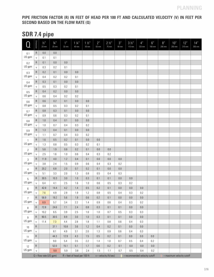
PLANNING
3.16
Q
Dimension
½”20 mm
¾”25 mm
1”32 mm
1 ¼”40 mm
1 ½”50 mm
2”63 mm
2 ½”75 mm
3”90 mm
3 ½”110 mm
4”125 mm
6”160 mm
8”200 mm
10”250 mm
12”315 mm
14”355 mm
0.1US gpm
R 0.0 0.0
v 0.1 0.1
0.2US gpm
R 0.1 0.0 0.0
v 0.3 0.2 0.1
0.3 US gpm
R 0.2 0.1 0.0 0.0
v 0.4 0.2 0.2 0.1
0.4 US gpm
R 0.3 0.1 0.0 0.0
v 0.5 0.3 0.2 0.1
0.5US gpm
R 0.4 0.2 0.0 0.0
v 0.6 0.4 0.2 0.2
0.6US gpm
R 0.6 0.2 0.1 0.0 0.0
v 0.8 0.5 0.3 0.2 0.1
0.7US gpm
R 0.8 0.3 0.1 0.0 0.0
v 0.9 0.6 0.3 0.2 0.1
0.8US gpm
R 1.0 0.4 0.1 0.0 0.0
v 1.0 0.7 0.4 0.3 0.2
0.9US gpm
R 1.3 0.4 0.1 0.0 0.0
v 1.1 0.7 0.4 0.3 0.2
1US gpm
R 1.6 0.5 0.2 0.1 0.0 0.0
v 1.3 0.8 0.5 0.3 0.2 0.1
2US gpm
R 5.6 1.9 0.6 0.2 0.1 0.0 0.0
v 2.5 1.6 1.0 0.6 0.4 0.3 0.2
3 US gpm
R 11.9 4.0 1.2 0.4 0.1 0.0 0.0 0.0
v 3.8 2.4 1.5 0.9 0.6 0.4 0.3 0.2
4US gpm
R 20.2 6.8 2.0 0.7 0.2 0.1 0.0 0.0
v 5.1 3.3 2.0 1.3 0.8 0.5 0.4 0.3
5US gpm
R 30.5 10.3 3.0 1.0 0.3 0.1 0.1 0.0 0.0
v 6.4 4.1 2.5 1.6 1.0 0.6 0.5 0.3 0.2
6US gpm
R 42.8 14.4 4.2 1.4 0.5 0.2 0.1 0.0 0.0 0.0
v 7.6 4.9 2.9 1.9 1.2 0.8 0.5 0.4 0.3 0.2
7US gpm
R 56.9 19.2 5.6 1.9 0.6 0.2 0.1 0.0 0.0 0.0
v 8.9 5.7 3.4 2.2 1.4 0.9 0.6 0.4 0.3 0.2
8US gpm
R 72.8 24.6 7.1 2.4 0.8 0.3 0.1 0.1 0.0 0.0
v 10.2 6.5 3.9 2.5 1.6 1.0 0.7 0.5 0.3 0.3
9US gpm
R 90.5 30.5 8.9 3.0 1.0 0.3 0.1 0.1 0.0 0.0
v 11.4 7.3 4.4 2.8 1.8 1.1 0.8 0.6 0.4 0.3
10US gpm
R 37.1 10.8 3.6 1.2 0.4 0.2 0.1 0.0 0.0
v 8.1 4.9 3.1 2.0 1.3 0.9 0.6 0.4 0.3
11US gpm
R 44.3 12.9 4.3 1.5 0.5 0.2 0.1 0.0 0.0 0.0
v 9.0 5.4 3.5 2.2 1.4 1.0 0.7 0.5 0.4 0.2
12US gpm
R 52.0 15.1 5.1 1.7 0.6 0.2 0.1 0.0 0.0 0.0
v 9.8 5.9 3.8 2.4 1.5 1.1 0.7 0.5 0.4 0.2
Q = flow rate (US gpm) R = feet of head per 100 ft v = velocity (ft/sec) - = recommended velocity cutoff - = maximum velocity cutoff
PIPE FRICTION FACTOR (R) IN FEET OF HEAD PER 100 FT AND CALCULATED VELOCITY (V) IN FEET PER SECOND BASED ON THE FLOW RATE (Q)
SDR 7.4 pipe
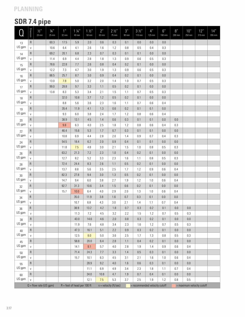
PLANNING
3.17
Q
Dimension
½”20 mm
¾”25 mm
1”32 mm
1 ¼”40 mm
1 ½”50 mm
2”63 mm
2 ½”75 mm
3”90 mm
3 ½”110 mm
4”125 mm
6”160 mm
8”200 mm
10”250 mm
12”315 mm
14”355 mm
13US gpm
R 60.3 17.5 5.9 2.0 0.6 0.3 0.1 0.0 0.0 0.0
v 10.6 6.4 4.1 2.6 1.6 1.2 0.8 0.5 0.4 0.3
14 US gpm
R 69.2 20.1 6.8 2.3 0.7 0.3 0.1 0.1 0.0 0.0
v 11.4 6.9 4.4 2.8 1.8 1.3 0.9 0.6 0.5 0.3
15US gpm
R 78.6 22.8 7.7 2.6 0.8 0.4 0.2 0.1 0.0 0.0
v 12.2 7.3 4.7 3.0 1.9 1.3 0.9 0.6 0.5 0.3
16US gpm
R 88.5 25.7 8.7 3.0 0.9 0.4 0.2 0.1 0.0 0.0
v 13.0 7.8 5.0 3.2 2.0 1.4 1.0 0.7 0.5 0.3
17US gpm
R 99.0 28.8 9.7 3.3 1.1 0.5 0.2 0.1 0.0 0.0
v 13.8 8.3 5.3 3.4 2.1 1.5 1.1 0.7 0.5 0.3
18US gpm
R 32.0 10.8 3.7 1.2 0.5 0.2 0.1 0.0 0.0
v 8.8 5.6 3.6 2.3 1.6 1.1 0.7 0.6 0.4
19US gpm
R 35.4 11.9 4.1 1.3 0.6 0.2 0.1 0.1 0.0
v 9.3 6.0 3.8 2.4 1.7 1.2 0.8 0.6 0.4
20US gpm
R 38.9 13.1 4.5 1.4 0.6 0.3 0.1 0.1 0.0 0.0
v 9.8 6.3 4.0 2.5 1.8 1.2 0.8 0.6 0.4 0.3
22US gpm
R 46.4 15.6 5.3 1.7 0.7 0.3 0.1 0.1 0.0 0.0
v 10.8 6.9 4.4 2.8 2.0 1.4 0.9 0.7 0.4 0.3
24US gpm
R 54.5 18.4 6.2 2.0 0.9 0.4 0.1 0.1 0.0 0.0
v 11.8 7.5 4.8 3.0 2.1 1.5 1.0 0.8 0.5 0.3
26US gpm
R 63.2 21.3 7.2 2.3 1.0 0.4 0.2 0.1 0.0 0.0
v 12.7 8.2 5.2 3.3 2.3 1.6 1.1 0.8 0.5 0.3
28US gpm
R 72.4 24.4 8.3 2.6 1.1 0.5 0.2 0.1 0.0 0.0
v 13.7 8.8 5.6 3.5 2.5 1.7 1.2 0.9 0.6 0.4
30US gpm
R 82.3 27.8 9.4 3.0 1.3 0.5 0.2 0.1 0.0 0.0
v 14.7 9.4 6.0 3.8 2.7 1.9 1.2 1.0 0.6 0.4
32US gpm
R 92.7 31.3 10.6 3.4 1.5 0.6 0.2 0.1 0.0 0.0
v 15.7 10.0 6.4 4.0 2.9 2.0 1.3 1.0 0.6 0.4
34US gpm
R 35.0 11.9 3.8 1.6 0.7 0.3 0.1 0.0 0.0
v 10.7 6.8 4.3 3.0 2.1 1.4 1.1 0.7 0.4
36US gpm
R 38.9 13.2 4.2 1.8 0.7 0.3 0.2 0.1 0.0 0.0
v 11.3 7.2 4.5 3.2 2.2 1.5 1.2 0.7 0.5 0.3
38US gpm
R 43.0 14.6 4.6 2.0 0.8 0.3 0.2 0.1 0.0 0.0
v 11.9 7.6 4.8 3.4 2.3 1.6 1.2 0.7 0.5 0.3
40US gpm
R 47.3 16.1 5.1 2.2 0.9 0.3 0.2 0.1 0.0 0.0
v 12.5 8.0 5.0 3.6 2.5 1.7 1.3 0.8 0.5 0.3
45US gpm
R 58.8 20.0 6.4 2.8 1.1 0.4 0.2 0.1 0.0 0.0
v 14.1 9.1 5.7 4.0 2.8 1.9 1.4 0.9 0.6 0.4
50US gpm
R 71.4 24.3 7.7 3.3 1.4 0.5 0.3 0.1 0.0 0.0
v 15.7 10.1 6.3 4.5 3.1 2.1 1.6 1.0 0.6 0.4
55US gpm
R 28.9 9.2 4.0 1.6 0.6 0.3 0.1 0.0 0.0
v 11.1 6.9 4.9 3.4 2.3 1.8 1.1 0.7 0.4
60US gpm
R 34.0 10.8 4.7 1.9 0.7 0.4 0.1 0.0 0.0
v 12.1 7.5 5.3 3.7 2.5 1.9 1.2 0.8 0.5
Q = flow rate (US gpm) R = feet of head per 100 ft v = velocity (ft/sec) - = recommended velocity cutoff - = maximum velocity cutoff
SDR 7.4 pipe
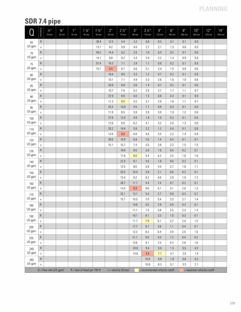
PLANNING
3.18
Q
Dimension
½”20 mm
¾”25 mm
1”32 mm
1 ¼”40 mm
1 ½”50 mm
2”63 mm
2 ½”75 mm
3”90 mm
3 ½”110 mm
4”125 mm
6”160 mm
8”200 mm
10”250 mm
12”315 mm
14”355 mm
65US gpm
R 39.4 12.5 5.4 2.2 0.8 0.5 0.1 0.1 0.0
v 13.1 8.2 5.8 4.0 2.7 2.1 1.3 0.8 0.5
70US gpm
R 45.2 14.4 6.2 2.5 1.0 0.5 0.2 0.1 0.0
v 14.1 8.8 6.2 4.3 2.9 2.2 1.4 0.9 0.6
75US gpm
R 51.4 16.3 7.1 2.9 1.1 0.6 0.2 0.1 0.0
v 15.1 9.4 6.7 4.6 3.1 2.4 1.5 0.9 0.6
80US gpm
R 18.4 8.0 3.3 1.2 0.7 0.2 0.1 0.0
v 10.1 7.1 4.9 3.3 2.6 1.6 1.0 0.6
85US gpm
R 20.6 8.9 3.6 1.4 0.7 0.2 0.1 0.0
v 10.7 7.6 5.2 3.5 2.7 1.7 1.1 0.7
90US gpm
R 22.9 9.9 4.0 1.5 0.8 0.3 0.1 0.0
v 11.3 8.0 5.5 3.7 2.9 1.8 1.1 0.7
95US gpm
R 25.3 10.9 4.5 1.7 0.9 0.3 0.1 0.0
v 11.9 8.5 5.9 3.9 3.0 1.9 1.2 0.8
100US gpm
R 27.8 12.0 4.9 1.9 1.0 0.3 0.1 0.0
v 12.6 8.9 6.2 4.1 3.2 2.0 1.3 0.8
110US gpm
R 33.2 14.4 5.9 2.2 1.2 0.4 0.1 0.0
v 13.8 9.8 6.8 4.6 3.5 2.2 1.4 0.9
120US gpm
R 39.0 16.9 6.9 2.6 1.4 0.4 0.1 0.1
v 15.1 10.7 7.4 5.0 3.8 2.3 1.5 1.0
130US gpm
R 19.6 8.0 3.0 1.6 0.5 0.2 0.1
v 11.6 8.0 5.4 4.2 2.5 1.6 1.0
140US gpm
R 22.4 9.1 3.5 1.9 0.6 0.2 0.1
v 12.5 8.6 5.8 4.5 2.7 1.8 1.1
150US gpm
R 25.5 10.4 3.9 2.1 0.6 0.2 0.1
v 13.4 9.2 6.2 4.8 2.9 1.9 1.2
160US gpm
R 28.7 11.7 4.4 2.4 0.7 0.2 0.1
v 14.3 9.9 6.6 5.1 3.1 2.0 1.3
170US gpm
R 32.1 13.1 5.0 2.7 0.8 0.3 0.1
v 15.1 10.5 7.0 5.4 3.3 2.1 1.4
180US gpm
R 14.6 5.5 2.9 0.9 0.3 0.1
v 11.1 7.5 5.8 3.5 2.3 1.4
190US gpm
R 16.1 6.1 3.3 1.0 0.3 0.1
v 11.7 7.9 6.1 3.7 2.4 1.5
200US gpm
R 17.7 6.7 3.6 1.1 0.4 0.1
v 12.3 8.3 6.4 3.9 2.5 1.6
220US gpm
R 21.1 8.0 4.3 1.3 0.4 0.2
v 13.6 9.1 7.0 4.3 2.8 1.8
240US gpm
R 24.8 9.4 5.0 1.5 0.5 0.2
v 14.8 9.9 7.7 4.7 3.0 1.9
260US gpm
R 10.9 5.8 1.8 0.6 0.2
v 10.8 8.3 5.1 3.3 2.1
Q = flow rate (US gpm) R = feet of head per 100 ft v = velocity (ft/sec) - = recommended velocity cutoff - = maximum velocity cutoff
SDR 7.4 pipe
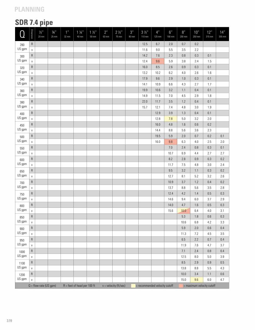
PLANNING
3.19
Q
Dimension
½”20 mm
¾”25 mm
1”32 mm
1 ¼”40 mm
1 ½”50 mm
2”63 mm
2 ½”75 mm
3”90 mm
3 ½”110 mm
4”125 mm
6”160 mm
8”200 mm
10”250 mm
12”315 mm
14”355 mm
280US gpm
R 12.5 6.7 2.0 0.7 0.2
v 11.6 9.0 5.5 3.5 2.2
300US gpm
R 14.2 7.6 2.3 0.8 0.3 0.1
v 12.4 9.6 5.9 3.8 2.4 1.5
320US gpm
R 16.0 8.5 2.6 0.9 0.3 0.1
v 13.2 10.2 6.2 4.0 2.6 1.6
340US gpm
R 17.9 9.6 2.9 1.0 0.3 0.1
v 14.1 10.9 6.6 4.3 2.7 1.7
360US gpm
R 19.9 10.6 3.2 1.1 0.4 0.1
v 14.9 11.5 7.0 4.5 2.9 1.8
380US gpm
R 22.0 11.7 3.5 1.2 0.4 0.1
v 15.7 12.1 7.4 4.8 3.0 1.9
400US gpm
R 12.9 3.9 1.3 0.4 0.1
v 12.8 7.8 5.0 3.2 2.0
450US gpm
R 16.0 4.8 1.6 0.6 0.2
v 14.4 8.8 5.6 3.6 2.3
500US gpm
R 19.5 5.9 2.0 0.7 0.2 0.1
v 16.0 9.8 6.3 4.0 2.5 2.0
550US gpm
R 7.0 2.4 0.8 0.3 0.1
v 10.7 6.9 4.4 2.7 2.7
600US gpm
R 8.2 2.8 0.9 0.3 0.2
v 11.7 7.5 4.8 3.0 2.4
650US gpm
R 9.5 3.2 1.1 0.3 0.2
v 12.7 8.1 5.2 3.2 2.6
700US gpm
R 10.9 3.7 1.2 0.4 0.2
v 13.7 8.8 5.6 3.5 2.8
750US gpm
R 12.4 4.2 1.4 0.5 0.3
v 14.6 9.4 6.0 3.7 2.9
800US gpm
R 14.0 4.7 1.6 0.5 0.3
v 15.6 10.0 6.4 4.0 3.1
850US gpm
R 5.3 1.8 0.6 0.3
v 10.6 6.8 4.2 3.3
900US gpm
R 5.9 2.0 0.6 0.4
v 11.3 7.2 4.5 3.5
950US gpm
R 6.5 2.2 0.7 0.4
v 11.9 7.6 4.7 3.7
1000US gpm
R 7.1 2.4 0.8 0.4
v 12.5 8.0 5.0 3.9
1100US gpm
R 8.5 2.9 0.9 0.5
v 13.8 8.8 5.5 4.3
1200US gpm
R 10.0 3.4 1.1 0.6
v 15.0 9.6 6.0 4.7
Q = flow rate (US gpm) R = feet of head per 100 ft v = velocity (ft/sec) - = recommended velocity cutoff - = maximum velocity cutoff
SDR 7.4 pipe
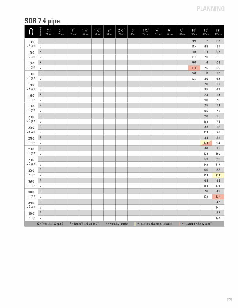
PLANNING
3.20
Q
Dimension
½”20 mm
¾”25 mm
1”32 mm
1 ¼”40 mm
1 ½”50 mm
2”63 mm
2 ½”75 mm
3”90 mm
3 ½”110 mm
4”125 mm
6”160 mm
8”200 mm
10”250 mm
12”315 mm
14”355 mm
1300US gpm
R 3.9 1.2 0.7
v 10.4 6.5 5.1
1400US gpm
R 4.5 1.4 0.8
v 11.2 7.0 5.5
1500US gpm
R 5.0 1.6 0.9
v 11.9 7.5 5.9
1600US gpm
R 5.6 1.8 1.0
v 12.7 8.0 6.3
1700US gpm
R 2.0 1.1
v 8.5 6.7
1800US gpm
R 2.3 1.3
v 9.0 7.0
1900US gpm
R 2.5 1.4
v 9.5 7.5
2000US gpm
R 2.8 1.5
v 10.0 7.9
2200US gpm
R 3.3 1.8
v 11.0 8.6
2400US gpm
R 3.8 2.1
v 12.0 9.4
2600US gpm
R 4.6 2.5
v 13.0 10.2
2800US gpm
R 5.3 2.9
v 14.0 11.0
3000US gpm
R 6.0 3.3
v 15.0 11.8
3200US gpm
R 6.8 3.8
v 16.0 12.6
3400US gpm
R 7.6 4.2
v 17.0 13.4
3600US gpm
R 4.7
v 14.1
3800US gpm
R 5.2
v 14.9
Q = flow rate (US gpm) R = feet of head per 100 ft v = velocity (ft/sec) - = recommended velocity cutoff - = maximum velocity cutoff
SDR 7.4 pipe
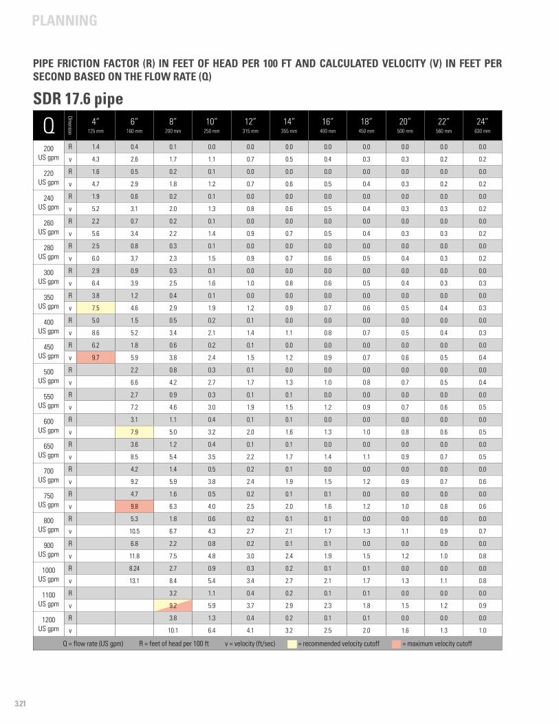
PLANNING
3.21
Q
Dimension
4”125 mm
6”160 mm
8”200 mm
10”250 mm
12”315 mm
14”355 mm
16”400 mm
18”450 mm
20”500 mm
22”560 mm
24”630 mm
200US gpm
R 1.4 0.4 0.1 0.0 0.0 0.0 0.0 0.0 0.0 0.0 0.0
v 4.3 2.6 1.7 1.1 0.7 0.5 0.4 0.3 0.3 0.2 0.2
220US gpm
R 1.6 0.5 0.2 0.1 0.0 0.0 0.0 0.0 0.0 0.0 0.0
v 4.7 2.9 1.8 1.2 0.7 0.6 0.5 0.4 0.3 0.2 0.2
240US gpm
R 1.9 0.6 0.2 0.1 0.0 0.0 0.0 0.0 0.0 0.0 0.0
v 5.2 3.1 2.0 1.3 0.8 0.6 0.5 0.4 0.3 0.3 0.2
260US gpm
R 2.2 0.7 0.2 0.1 0.0 0.0 0.0 0.0 0.0 0.0 0.0
v 5.6 3.4 2.2 1.4 0.9 0.7 0.5 0.4 0.3 0.3 0.2
280US gpm
R 2.5 0.8 0.3 0.1 0.0 0.0 0.0 0.0 0.0 0.0 0.0
v 6.0 3.7 2.3 1.5 0.9 0.7 0.6 0.5 0.4 0.3 0.2
300US gpm
R 2.9 0.9 0.3 0.1 0.0 0.0 0.0 0.0 0.0 0.0 0.0
v 6.4 3.9 2.5 1.6 1.0 0.8 0.6 0.5 0.4 0.3 0.3
350US gpm
R 3.8 1.2 0.4 0.1 0.0 0.0 0.0 0.0 0.0 0.0 0.0
v 7.5 4.6 2.9 1.9 1.2 0.9 0.7 0.6 0.5 0.4 0.3
400US gpm
R 5.0 1.5 0.5 0.2 0.1 0.0 0.0 0.0 0.0 0.0 0.0
v 8.6 5.2 3.4 2.1 1.4 1.1 0.8 0.7 0.5 0.4 0.3
450US gpm
R 6.2 1.8 0.6 0.2 0.1 0.0 0.0 0.0 0.0 0.0 0.0
v 9.7 5.9 3.8 2.4 1.5 1.2 0.9 0.7 0.6 0.5 0.4
500US gpm
R 2.2 0.8 0.3 0.1 0.0 0.0 0.0 0.0 0.0 0.0
v 6.6 4.2 2.7 1.7 1.3 1.0 0.8 0.7 0.5 0.4
550US gpm
R 2.7 0.9 0.3 0.1 0.1 0.0 0.0 0.0 0.0 0.0
v 7.2 4.6 3.0 1.9 1.5 1.2 0.9 0.7 0.6 0.5
600 US gpm
R 3.1 1.1 0.4 0.1 0.1 0.0 0.0 0.0 0.0 0.0
v 7.9 5.0 3.2 2.0 1.6 1.3 1.0 0.8 0.6 0.5
650 US gpm
R 3.6 1.2 0.4 0.1 0.1 0.0 0.0 0.0 0.0 0.0
v 8.5 5.4 3.5 2.2 1.7 1.4 1.1 0.9 0.7 0.5
700US gpm
R 4.2 1.4 0.5 0.2 0.1 0.0 0.0 0.0 0.0 0.0
v 9.2 5.9 3.8 2.4 1.9 1.5 1.2 0.9 0.7 0.6
750US gpm
R 4.7 1.6 0.5 0.2 0.1 0.1 0.0 0.0 0.0 0.0
v 9.8 6.3 4.0 2.5 2.0 1.6 1.2 1.0 0.8 0.6
800US gpm
R 5.3 1.8 0.6 0.2 0.1 0.1 0.0 0.0 0.0 0.0
v 10.5 6.7 4.3 2.7 2.1 1.7 1.3 1.1 0.9 0.7
900US gpm
R 6.8 2.2 0.8 0.2 0.1 0.1 0.0 0.0 0.0 0.0
v 11.8 7.5 4.8 3.0 2.4 1.9 1.5 1.2 1.0 0.8
1000US gpm
R 8.24 2.7 0.9 0.3 0.2 0.1 0.1 0.0 0.0 0.0
v 13.1 8.4 5.4 3.4 2.7 2.1 1.7 1.3 1.1 0.8
1100US gpm
R 3.2 1.1 0.4 0.2 0.1 0.1 0.0 0.0 0.0
v 9.2 5.9 3.7 2.9 2.3 1.8 1.5 1.2 0.9
1200US gpm
R 3.8 1.3 0.4 0.2 0.1 0.1 0.0 0.0 0.0
v 10.1 6.4 4.1 3.2 2.5 2.0 1.6 1.3 1.0
Q = flow rate (US gpm) R = feet of head per 100 ft v = velocity (ft/sec) - = recommended velocity cutoff - = maximum velocity cutoff
PIPE FRICTION FACTOR (R) IN FEET OF HEAD PER 100 FT AND CALCULATED VELOCITY (V) IN FEET PER SECOND BASED ON THE FLOW RATE (Q)
SDR 17.6 pipe
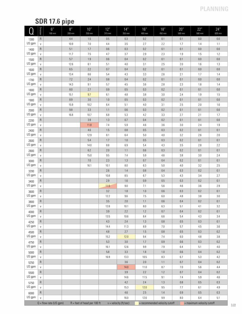
PLANNING
3.22
Q
Dimension
6”160 mm
8”200 mm
10”250 mm
12”315 mm
14”355 mm
16”400 mm
18”450 mm
20”500 mm
22”560 mm
24”630 mm
1300 US gpm
R 4.4 1.5 0.5 0.3 0.2 0.1 0.1 0.0 0.0
v 10.9 7.0 4.4 3.5 2.7 2.2 1.7 1.4 1.1
1400US gpm
R 5.1 1.7 0.6 0.3 0.2 0.1 0.1 0.0 0.0
v 11.7 7.5 4.7 3.7 2.9 2.3 1.9 1.5 1.2
1500US gpm
R 5.7 1.9 0.6 0.4 0.2 0.1 0.1 0.0 0.0
v 12.6 8.1 5.1 4.0 3.1 2.5 2.0 1.6 1.3
1600US gpm
R 6.5 2.2 0.7 0.4 0.2 0.1 0.1 0.0 0.0
v 13.4 8.6 5.4 4.3 3.3 2.6 2.1 1.7 1.4
1700US gpm
R 7.2 2.4 0.8 0.4 0.2 0.1 0.1 0.0 0.0
v 14.3 9.1 5.7 4.5 3.6 2.8 2.3 1.8 1.4
1800US gpm
R 8.0 2.7 0.9 0.5 0.3 0.2 0.1 0.1 0.0
v 15.1 9.7 6.1 4.8 3.8 3.0 2.4 1.9 1.5
1900US gpm
R 8.9 3.0 1.0 0.5 0.3 0.2 0.1 0.1 0.0
v 15.9 10.2 6.4 5.1 4.0 3.1 2.5 2.0 1.6
2000US gpm
R 9.8 3.3 1.1 0.6 0.3 0.2 0.1 0.1 0.0
v 16.8 10.7 6.8 5.3 4.2 3.3 2.7 2.1 1.7
2200US gpm
R 3.9 1.3 0.7 0.4 0.2 0.1 0.1 0.0
v 11.8 7.4 5.9 4.6 3.6 3.0 2.4 1.9
2400US gpm
R 4.6 1.5 0.8 0.5 0.3 0.2 0.1 0.1
v 12.9 8.1 6.4 5.0 4.0 3.2 2.6 2.0
2600US gpm
R 5.4 1.7 1.0 0.5 0.3 0.2 0.1 0.1
v 14.0 8.8 6.9 5.4 4.3 3.5 2.8 2.2
2800US gpm
R 6.2 2.0 1.1 0.6 0.3 0.2 0.1 0.1
v 15.0 9.5 7.4 5.9 4.6 3.8 3.0 2.4
3000 US gpm
R 7.0 2.3 1.3 0.7 0.4 0.2 0.1 0.1
v 16.1 10.1 8.0 6.3 5.0 4.0 3.2 2.5
3200 US gpm
R 2.6 1.4 0.8 0.4 0.3 0.2 0.1
v 10.8 8.5 6.7 5.3 4.3 3.4 2.7
3400US gpm
R 2.9 1.6 0.9 0.5 0.3 0.2 0.1
v 11.5 9.0 7.1 5.6 4.6 3.6 2.9
3600US gpm
R 3.2 1.8 1.0 0.6 0.3 0.2 0.1
v 12.2 9.6 7.5 6.0 4.8 3.8 3.0
3800US gpm
R 3.5 2.0 1.1 0.6 0.4 0.2 0.1
v 12.8 10.1 8.0 6.3 5.1 4.1 3.2
4000US gpm
R 3.9 2.2 1.2 0.7 0.4 0.2 0.1
v 13.5 10.6 8.4 6.6 5.4 4.3 3.4
4250US gpm
R 4.3 2.4 1.3 0.8 0.5 0.3 0.1
v 14.4 11.3 8.9 7.0 5.7 4.5 3.6
4500US gpm
R 4.8 2.7 1.5 0.8 0.5 0.3 0.2
v 15.2 12.0 9.4 7.4 6.0 4.8 3.8
4750US gpm
R 5.3 3.0 1.7 0.9 0.6 0.3 0.2
v 16.1 12.6 9.9 7.9 6.4 5.1 4.0
5000 US gpm
R 5.8 3.3 1.8 1.0 0.6 0.4 0.2
v 16.9 13.3 10.5 8.3 6.7 5.3 4.2
5250 US gpm
R 3.6 2.0 1.1 0.7 0.4 0.2
v 14.0 11.0 8.7 7.0 5.6 4.4
5500US gpm
R 3.9 2.2 1.2 0.7 0.4 0.2
v 14.6 11.5 9.1 7.4 5.9 4.6
5750US gpm
R 4.2 2.4 1.3 0.8 0.5 0.3
v 15.3 12.0 9.5 7.7 6.1 4.9
6000US gpm
R 4.6 2.5 1.4 0.9 0.5 0.3
v 16.0 12.6 9.9 8.0 6.4 5.1
Q = flow rate (US gpm) R = feet of head per 100 ft v = velocity (ft/sec) - = recommended velocity cutoff - = maximum velocity cutoff
SDR 17.6 pipe
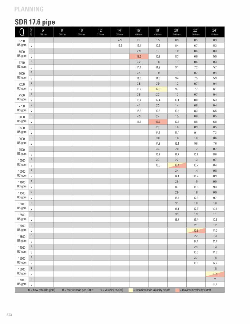
PLANNING
3.23
Q
Dimension
6”160 mm
8”200 mm
10”250 mm
12”315 mm
14”355 mm
16”400 mm
18”450 mm
20”500 mm
22”560 mm
24”630 mm
6250US gpm
R 4.9 2.7 1.5 0.9 0.5 0.3
v 16.6 13.1 10.3 8.4 6.7 5.3
6500US gpm
R 2.9 1.7 1.0 0.6 0.3
v 13.6 10.8 8.7 6.9 5.5
6750US gpm
R 3.2 1.8 1.1 0.6 0.3
v 14.1 11.2 9.1 7.2 5.7
7000US gpm
R 3.4 1.9 1.1 0.7 0.4
v 14.6 11.6 9.4 7.5 5.9
7250US gpm
R 3.6 2.0 1.2 0.7 0.4
v 15.2 12.0 9.7 7.7 6.1
7500US gpm
R 3.8 2.2 1.3 0.7 0.4
v 15.7 12.4 10.1 8.0 6.3
7750US gpm
R 4.1 2.3 1.4 0.8 0.4
v 16.2 12.8 10.4 8.3 6.5
8000US gpm
R 4.3 2.4 1.5 0.8 0.5
v 16.7 13.2 10.7 8.5 6.8
8500US gpm
R 2.7 1.6 0.9 0.5
v 14.1 11.4 9.1 7.2
9000US gpm
R 3.0 1.8 1.0 0.6
v 14.9 12.1 9.6 7.6
9500 US gpm
R 3.3 2.0 1.2 0.7
v 15.7 12.7 10.2 8.0
10000 US gpm
R 3.7 2.2 1.3 0.7
v 16.5 13.4 10.7 8.4
10500US gpm
R 2.4 1.4 0.8
v 14.1 11.2 8.9
11000US gpm
R 2.6 1.5 0.9
v 14.8 11.8 9.3
11500US gpm
R 2.9 1.6 0.9
v 15.4 12.3 9.7
12000US gpm
R 3.1 1.8 1.0
v 16.1 12.8 10.1
12500US gpm
R 3.3 1.9 1.1
v 16.8 13.4 10.6
13000US gpm
R 2.1 1.2
v 13.9 11.0
13500US gpm
R 2.2 1.3
v 14.4 11.4
14000 US gpm
R 2.4 1.3
v 15.0 11.8
15000 US gpm
R 2.7 1.5
v 16.0 12.7
16000US gpm
R 1.8
v 13.5
17000US gpm
R 2
v 14.4
Q = flow rate (US gpm) R = feet of head per 100 ft v = velocity (ft/sec) - = recommended velocity cutoff - = maximum velocity cutoff
SDR 17.6 pipe

PLANNING
3.24
0.0
0.5
1.0
1.5
2.0
2.5
3.0
0 100 200 300 400 500
Hea
d lo
ss, p
si /
100
ft.
Flow rate, gpm
Pressure Loss vs. Flow Rate3” thru 8”, SDR 9
3” (90 mm)
3-½” (110 mm)
4” (125 mm)
6” (160 mm)
8” (200 mm)
0
5
10
15
20
25
0 20 40 60 80 100 120
Hea
d lo
ss, p
si /
100
ft.
Flow rate, gpm
Pressure Loss vs. Flow Rate1” thru 1-2 1/2”, SDR 9
1-¼” (40 mm)
1-½” (50 mm)
2” (63 mm)
2-½” (75 mm)
1” (32 mm)
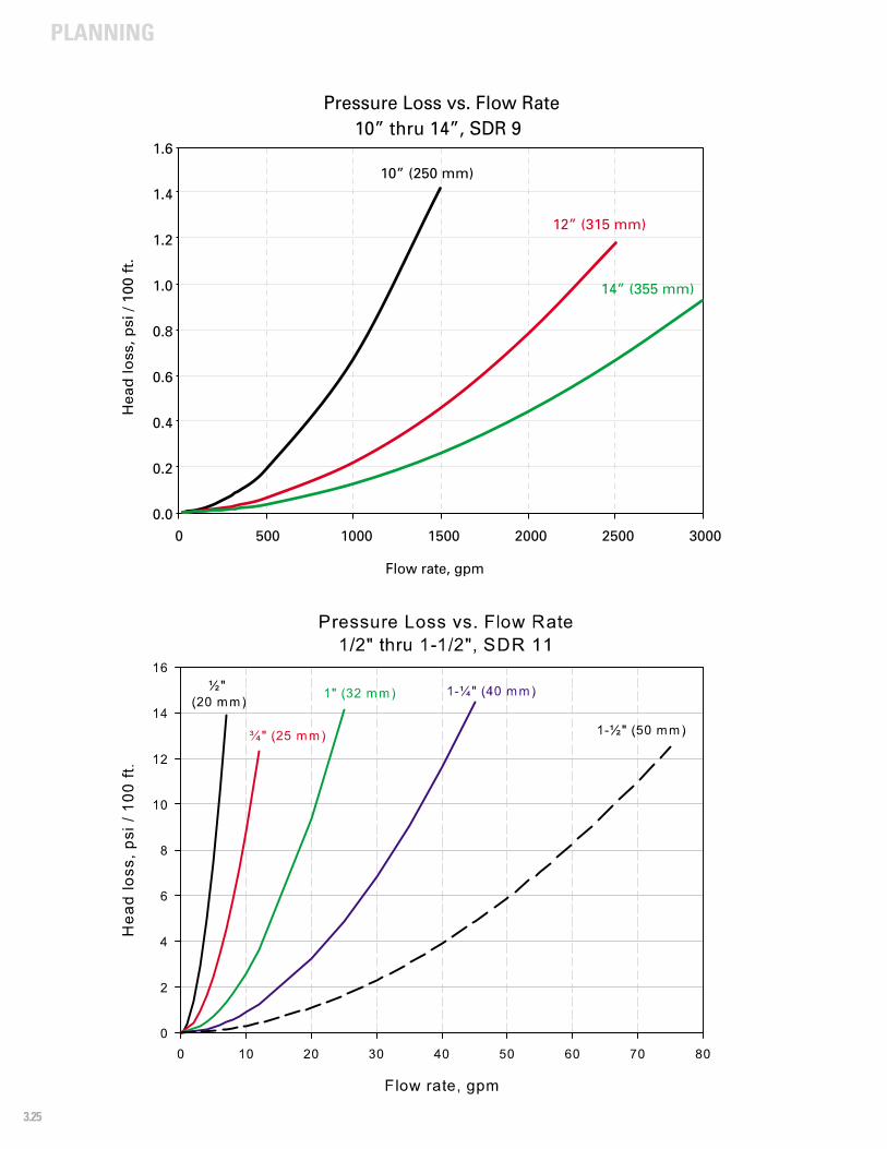
PLANNING
3.25
0.0
0.2
0.4
0.6
0.8
1.0
1.2
1.4
1.6
0 500 1000 1500 2000 2500 3000
Hea
d lo
ss, p
si /
100
ft.
Flow rate, gpm
Pressure Loss vs. Flow Rate10” thru 14”, SDR 9
10” (250 mm)
12” (315 mm)
14” (355 mm)
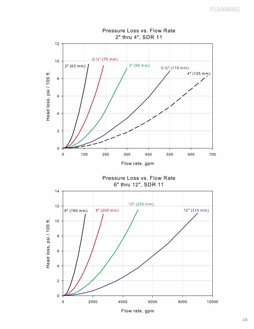
PLANNING
3.26

PLANNING
3.27
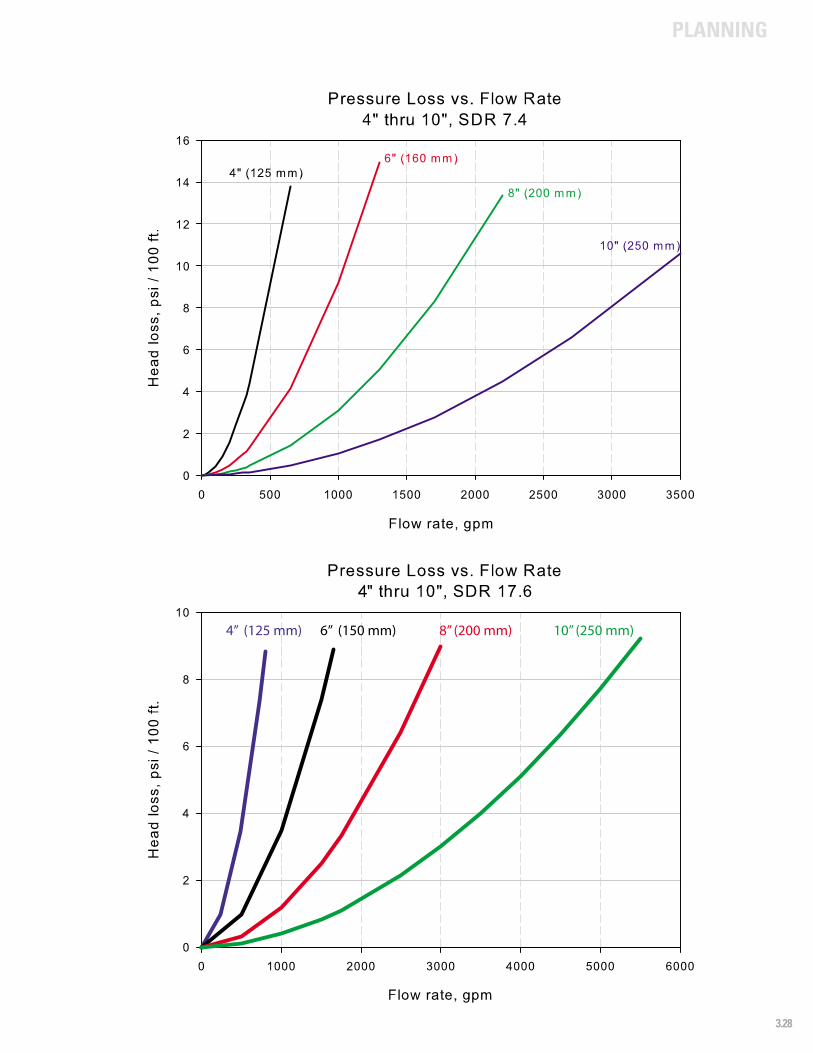
PLANNING
3.28
6” (150 mm)4” (125 mm) 8” (200 mm) 10” (250 mm)
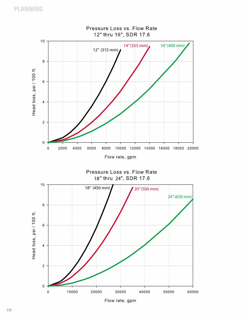
PLANNING
3.29
18 24
18” (450 mm) 20” (500 mm)
24” (630 mm)
12” (315 mm)14” (355 mm) 16” (400 mm)
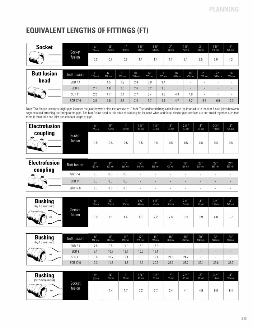
PLANNING
3.30
SocketSocketfusion
½”20 mm
¾”25 mm
1”32 mm
1 ¼”40 mm
1 ½”50 mm
2”63 mm
2 ½”75 mm
3”90 mm
3 ½”110 mm
4”125 mm
0.5 0.7 0.9 1.1 1.4 1.7 2.1 2.5 3.0 4.2
EQUIVALENT LENGTHS OF FITTINGS (FT)
Butt fusion bead
Butt fusion 4”125 mm
6”160 mm
8”200 mm
10”250 mm
12”315 mm
14” 355 mm
16”400 mm
18”450 mm
20”500 mm
22”560 mm
24”630 mm
SDR 7.4 - 1.5 1.9 2.4 3.0 3.4 - - - - -
SDR 9 2.1 1.6 2.0 2.6 3.2 3.6 - - - - -
SDR 11 2.2 1.7 2.1 2.7 3.4 3.8 4.3 4.8 - - -
SDR 17.6 3.0 1.9 2.3 2.9 3.7 4.1 4.7 5.2 5.8 6.5 7.3
Electrofusion coupling Socket
fusion
½”20 mm
¾”25 mm
1”32 mm
1 ¼”40 mm
1 ½”50 mm
2”63 mm
2 ½”75 mm
3”90 mm
3 ½”110 mm
4”125 mm
0.5 0.5 0.5 0.5 0.5 0.5 0.5 0.5 0.5 0.5
Bushing(by 1 dimension)
Socketfusion
½”20 mm
¾”25 mm
1”32 mm
1 ¼”40 mm
1 ½”50 mm
2”63 mm
2 ½”75 mm
3”90 mm
3 ½”110 mm
4”125 mm
0.9 1.1 1.4 1.7 2.2 2.8 3.3 3.9 4.8 6.7
Note: The friction loss for straight pipe includes the joint between pipe sections every 19 feet. The fabricated fittings also include the losses due to the butt fusion joints between segments and attaching the fitting to the pipe. The butt fusion bead in this table should only be included when additional shorter pipe sections are butt fused together such that there is more than one joint per standard length of pipe.
Electrofusion coupling
Butt fusion 6”160 mm
8”200 mm
10”250 mm
12”315 mm
14” 355 mm
16”400 mm
18”450 mm
20”500 mm
22”560 mm
24”630 mm
SDR 7.4 0.5 0.5 0.5 - - - - - - -
SDR 11 0.5 0.5 0.5 - - - - - - -
SDR 17.6 0.5 0.5 0.5 - - - - - - -
Bushing(by 1 dimension)
Butt fusion 6”160 mm
8”200 mm
10”250 mm
12”315 mm
14” 355 mm
16”400 mm
18”450 mm
20”500 mm
22”560 mm
24”630 mm
SDR 7.4 7.6 9.5 11.9 15.0 16.9 - - - - -
SDR 9 8.1 10.2 12.7 16.0 18.1 - - - - -
SDR 11 8.6 10.7 13.4 16.9 19.1 21.5 24.2 - - -
SDR 17.6 9.3 11.6 14.5 18.3 20.7 23.3 26.2 29.1 32.6 36.7
Bushing(by 2 dimensions)
Socketfusion
½”20 mm
¾”25 mm
1”32 mm
1 ¼”40 mm
1 ½”50 mm
2”63 mm
2 ½”75 mm
3”90 mm
3 ½”110 mm
4”125 mm
- 1.4 1.7 2.2 2.7 3.4 4.1 4.9 6.0 8.4
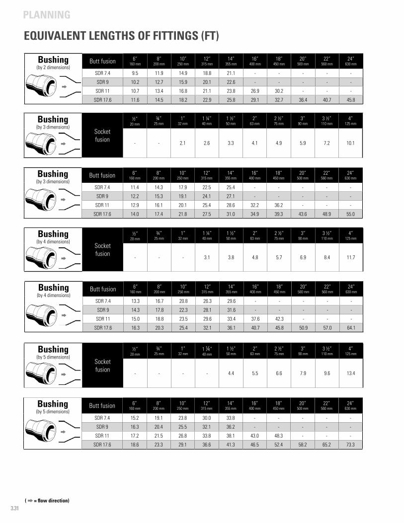
PLANNING
3.31
Bushing(by 2 dimensions)
Butt fusion 6”160 mm
8”200 mm
10”250 mm
12”315 mm
14” 355 mm
16”400 mm
18”450 mm
20”500 mm
22”560 mm
24”630 mm
SDR 7.4 9.5 11.9 14.9 18.8 21.1 - - - - -
SDR 9 10.2 12.7 15.9 20.1 22.6 - - - - -
SDR 11 10.7 13.4 16.8 21.1 23.8 26.9 30.2 - - -
SDR 17.6 11.6 14.5 18.2 22.9 25.8 29.1 32.7 36.4 40.7 45.8
Bushing(by 3 dimensions)
Butt fusion 6”160 mm
8”200 mm
10”250 mm
12”315 mm
14” 355 mm
16”400 mm
18”450 mm
20”500 mm
22”560 mm
24”630 mm
SDR 7.4 11.4 14.3 17.9 22.5 25.4 - - - - -
SDR 9 12.2 15.3 19.1 24.1 27.1 - - - - -
SDR 11 12.9 16.1 20.1 25.4 28.6 32.2 36.2 - - -
SDR 17.6 14.0 17.4 21.8 27.5 31.0 34.9 39.3 43.6 48.9 55.0
( = flow direction)
EQUIVALENT LENGTHS OF FITTINGS (FT)
Bushing(by 4 dimensions)
Butt fusion 6”160 mm
8”200 mm
10”250 mm
12”315 mm
14” 355 mm
16”400 mm
18”450 mm
20”500 mm
22”560 mm
24”630 mm
SDR 7.4 13.3 16.7 20.8 26.3 29.6 - - - - -
SDR 9 14.3 17.8 22.3 28.1 31.6 - - - - -
SDR 11 15.0 18.8 23.5 29.6 33.4 37.6 42.3 - - -
SDR 17.6 16.3 20.3 25.4 32.1 36.1 40.7 45.8 50.9 57.0 64.1
Bushing(by 5 dimensions)
Butt fusion 6”160 mm
8”200 mm
10”250 mm
12”315 mm
14” 355 mm
16”400 mm
18”450 mm
20”500 mm
22”560 mm
24”630 mm
SDR 7.4 15.2 19.1 23.8 30.0 33.8 - - - - -
SDR 9 16.3 20.4 25.5 32.1 36.2 - - - - -
SDR 11 17.2 21.5 26.8 33.8 38.1 43.0 48.3 - - -
SDR 17.6 18.6 23.3 29.1 36.6 41.3 46.5 52.4 58.2 65.2 73.3
Bushing(by 3 dimensions)
Socketfusion
½”20 mm
¾”25 mm
1”32 mm
1 ¼”40 mm
1 ½”50 mm
2”63 mm
2 ½”75 mm
3”90 mm
3 ½”110 mm
4”125 mm
- - 2.1 2.6 3.3 4.1 4.9 5.9 7.2 10.1
Bushing(by 4 dimensions)
Socketfusion
½”20 mm
¾”25 mm
1”32 mm
1 ¼”40 mm
1 ½”50 mm
2”63 mm
2 ½”75 mm
3”90 mm
3 ½”110 mm
4”125 mm
- - - 3.1 3.8 4.8 5.7 6.9 8.4 11.7
Bushing(by 5 dimensions)
Socketfusion
½”20 mm
¾”25 mm
1”32 mm
1 ¼”40 mm
1 ½”50 mm
2”63 mm
2 ½”75 mm
3”90 mm
3 ½”110 mm
4”125 mm
- - - - 4.4 5.5 6.6 7.9 9.6 13.4
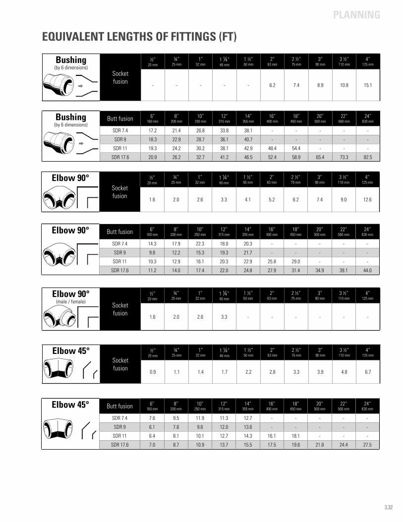
PLANNING
3.32
Bushing(by 6 dimensions)
Socketfusion
½”20 mm
¾”25 mm
1”32 mm
1 ¼”40 mm
1 ½”50 mm
2”63 mm
2 ½”75 mm
3”90 mm
3 ½”110 mm
4”125 mm
- - - - - 6.2 7.4 8.9 10.8 15.1
Elbow 90° Butt fusion 6”160 mm
8”200 mm
10”250 mm
12”315 mm
14” 355 mm
16”400 mm
18”450 mm
20”500 mm
22”560 mm
24”630 mm
SDR 7.4 14.3 17.9 22.3 18.0 20.3 - - - - -
SDR 9 9.8 12.2 15.3 19.3 21.7 - - - - -
SDR 11 10.3 12.9 16.1 20.3 22.9 25.8 29.0 - - -
SDR 17.6 11.2 14.0 17.4 22.0 24.8 27.9 31.4 34.9 39.1 44.0
Elbow 90°(male / female)
Socketfusion
½”20 mm
¾”25 mm
1”32 mm
1 ¼”40 mm
1 ½”50 mm
2”63 mm
2 ½”75 mm
3”90 mm
3 ½”110 mm
4”125 mm
1.6 2.0 2.6 3.3 - - - - - -
Elbow 45° Butt fusion 6”160 mm
8”200 mm
10”250 mm
12”315 mm
14” 355 mm
16”400 mm
18”450 mm
20”500 mm
22”560 mm
24”630 mm
SDR 7.4 7.6 9.5 11.9 11.3 12.7 - - - - -
SDR 9 6.1 7.6 9.6 12.0 13.6 - - - - -
SDR 11 6.4 8.1 10.1 12.7 14.3 16.1 18.1 - - -
SDR 17.6 7.0 8.7 10.9 13.7 15.5 17.5 19.6 21.8 24.4 27.5
Bushing(by 6 dimensions)
Butt fusion 6”160 mm
8”200 mm
10”250 mm
12”315 mm
14” 355 mm
16”400 mm
18”450 mm
20”500 mm
22”560 mm
24”630 mm
SDR 7.4 17.2 21.4 26.8 33.8 38.1 - - - - -
SDR 9 18.3 22.9 28.7 36.1 40.7 - - - - -
SDR 11 19.3 24.2 30.2 38.1 42.9 48.4 54.4 - - -
SDR 17.6 20.9 26.2 32.7 41.2 46.5 52.4 58.9 65.4 73.3 82.5
Elbow 90°Socketfusion
½”20 mm
¾”25 mm
1”32 mm
1 ¼”40 mm
1 ½”50 mm
2”63 mm
2 ½”75 mm
3”90 mm
3 ½”110 mm
4”125 mm
1.6 2.0 2.6 3.3 4.1 5.2 6.2 7.4 9.0 12.6
Elbow 45°Socketfusion
½”20 mm
¾”25 mm
1”32 mm
1 ¼”40 mm
1 ½”50 mm
2”63 mm
2 ½”75 mm
3”90 mm
3 ½”110 mm
4”125 mm
0.9 1.1 1.4 1.7 2.2 2.8 3.3 3.9 4.8 6.7
EQUIVALENT LENGTHS OF FITTINGS (FT)
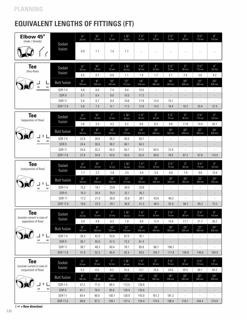
PLANNING
3.33 ( = flow direction)
Elbow 45°(male / female)
Socketfusion
½”20 mm
¾”25 mm
1”32 mm
1 ¼”40 mm
1 ½”50 mm
2”63 mm
2 ½”75 mm
3”90 mm
3 ½”110 mm
4”125 mm
0.9 1.1 1.4 1.7 - - - - - -
Tee(thru-flow)
Socketfusion
½”20 mm
¾”25 mm
1”32 mm
1 ¼”40 mm
1 ½”50 mm
2”63 mm
2 ½”75 mm
3”90 mm
3 ½”110 mm
4”125 mm
0.5 0.7 0.9 1.1 1.4 1.7 2.1 2.5 3.0 4.2
Butt fusion 6”160 mm
8”200 mm
10”250 mm
12”315 mm
14” 355 mm
16”400 mm
18”450 mm
20”500 mm
22”560 mm
24”630 mm
SDR 7.4 4.8 6.0 7.4 9.4 10.6 - - - - -
SDR 9 5.1 6.4 8.0 10.0 11.3 - - - - -
SDR 11 5.4 6.7 8.4 10.6 11.9 13.4 15.1 - - -
SDR 17.6 5.8 7.3 9.1 11.5 12.9 14.5 16.4 18.2 20.4 22.9
Tee(separation of flow)
Socketfusion
½”20 mm
¾”25 mm
1”32 mm
1 ¼”40 mm
1 ½”50 mm
2”63 mm
2 ½”75 mm
3”90 mm
3 ½”110 mm
4”125 mm
2.6 3.3 4.2 5.2 6.6 8.3 9.8 11.8 14.4 20.1
Butt fusion 6”160 mm
8”200 mm
10”250 mm
12”315 mm
14” 355 mm
16”400 mm
18”450 mm
20”500 mm
22”560 mm
24”630 mm
SDR 7.4 22.9 28.6 35.7 45.0 50.7 - - - - -
SDR 9 24.4 30.6 38.2 48.1 54.3 - - - - -
SDR 11 25.8 32.2 40.3 50.7 57.2 64.5 72.5 - - -
SDR 17.6 27.9 34.9 43.6 55.0 62.0 69.8 78.5 87.2 97.8 110.0
Tee(conjunction of flow)
Socketfusion
½”20 mm
¾”25 mm
1”32 mm
1 ¼”40 mm
1 ½”50 mm
2”63 mm
2 ½”75 mm
3”90 mm
3 ½”110 mm
4”125 mm
1.7 2.2 2.8 3.5 4.4 5.5 6.6 7.9 9.6 13.4
Butt fusion 6”160 mm
8”200 mm
10”250 mm
12”315 mm
14” 355 mm
16”400 mm
18”450 mm
20”500 mm
22”560 mm
24”630 mm
SDR 7.4 15.2 19.1 23.8 30.0 33.8 - - - - -
SDR 9 16.3 20.4 25.5 32.1 36.2 - - - - -
SDR 11 17.2 21.5 26.8 33.8 38.1 43.0 48.3 - - -
SDR 17.6 18.6 23.3 29.1 36.6 41.3 46.5 52.4 58.2 65.2 73.3
Tee(counter current in case of
separation of flow)
Socketfusion
½”20 mm
¾”25 mm
1”32 mm
1 ¼”40 mm
1 ½”50 mm
2”63 mm
2 ½”75 mm
3”90 mm
3 ½”110 mm
4”125 mm
3.9 4.9 6.3 7.9 9.9 12.4 14.8 17.7 21.7 30.2
Butt fusion 6”160 mm
8”200 mm
10”250 mm
12”315 mm
14” 355 mm
16”400 mm
18”450 mm
20”500 mm
22”560 mm
24”630 mm
SDR 7.4 34.3 42.9 53.6 67.5 76.1 - - - - -
SDR 9 36.7 45.8 57.3 72.2 81.4 - - - - -
SDR 11 38.7 48.3 60.4 76.1 85.8 96.7 108.7 - - -
SDR 17.6 41.9 52.3 65.4 82.4 93.0 104.7 117.8 130.9 146.6 164.9
Tee(counter current in case of
conjunction of flow)
Socketfusion
½”20 mm
¾”25 mm
1”32 mm
1 ¼”40 mm
1 ½”50 mm
2”63 mm
2 ½”75 mm
3”90 mm
3 ½”110 mm
4”125 mm
5.2 6.5 8.2 10.4 13.1 16.4 24.6 29.5 36.1 50.3
Butt fusion 6”160 mm
8”200 mm
10”250 mm
12”315 mm
14” 355 mm
16”400 mm
18”450 mm
20”500 mm
22”560 mm
24”630 mm
SDR 7.4 57.2 71.5 89.3 112.5 126.8 - - - - -
SDR 9 61.1 76.4 95.6 120.4 135.6 - - - - -
SDR 11 64.4 80.5 100.7 126.9 143.0 161.2 181.2 - - -
SDR 17.6 69.8 87.2 109.1 137.4 154.9 174.5 196.4 218.1 244.4 274.9
EQUIVALENT LENGTHS OF FITTINGS (FT)
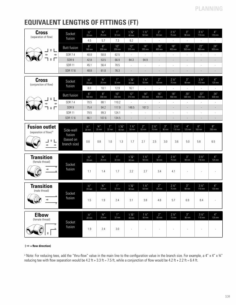
PLANNING
3.34
( = flow direction)
Cross(separation of flow)
Socketfusion
½”20 mm
¾”25 mm
1”32 mm
1 ¼”40 mm
1 ½”50 mm
2”63 mm
2 ½”75 mm
3”90 mm
3 ½”110 mm
4”125 mm
4.5 5.7 7.3 9.2 - - - - - -
Butt fusion 6”160 mm
8”200 mm
10”250 mm
12”315 mm
14”355 mm
16”400 mm
18”450 mm
20”500 mm
22”560 mm
24”630 mm
SDR 7.4 40.0 50.0 62.5 - - - - - - -
SDR 9 42.8 53.5 66.9 84.3 94.9 - - - - -
SDR 11 45.1 56.4 70.5 - - - - - - -
SDR 17.6 48.8 61.0 76.3 - - - - - - -
Cross(conjunction of flow)
Socketfusion
½”20 mm
¾”25 mm
1”32 mm
1 ¼”40 mm
1 ½”50 mm
2”63 mm
2 ½”75 mm
3”90 mm
3 ½”110 mm
4”125 mm
8.0 10.1 12.9 16.1 - - - - - -
Butt fusion 6”160 mm
8”200 mm
10”250 mm
12”315 mm
14”355 mm
16”400 mm
18”450 mm
20”500 mm
22”560 mm
24”630 mm
SDR 7.4 70.5 88.1 110.2 - - - - - - -
SDR 9 75.4 94.2 117.9 148.5 167.3 - - - - -
SDR 11 79.5 99.3 124.1 - - - - - - -
SDR 17.6 86.1 107.6 134.5 - - - - - - -
Fusion outlet(separation of flow) a Side-wall
fusion(based on
branch size)
½”20 mm
¾”25 mm
1”32 mm
1 ¼”40 mm
1 ½”50 mm
2”63 mm
2 ½”75 mm
3”90 mm
3 ½”110 mm
4”125 mm
6”160 mm
8”200 mm
0.6 0.8 1.0 1.3 1.7 2.1 2.5 3.0 3.6 5.0 5.8 6.5
Transition(female thread)
Socketfusion
½”20 mm
¾”25 mm
1”32 mm
1 ¼”40 mm
1 ½”50 mm
2”63 mm
2 ½”75 mm
3”90 mm
3 ½”110 mm
4”125 mm
1.1 1.4 1.7 2.2 2.7 3.4 4.1 - - -
a Note: For reducing tees, add the “thru-flow” value in the main line to the configuration value in the branch size. For example, a 4” x 4” x ¾” reducing tee with flow separation would be 4.2 ft + 3.3 ft = 7.5 ft, while a conjunction of flow would be 4.2 ft + 2.2 ft = 6.4 ft.
EQUIVALENT LENGTHS OF FITTINGS (FT)
Transition(male thread)
Socketfusion
½”20 mm
¾”25 mm
1”32 mm
1 ¼”40 mm
1 ½”50 mm
2”63 mm
2 ½”75 mm
3”90 mm
3 ½”110 mm
4”125 mm
1.5 1.9 2.4 3.1 3.8 4.8 5.7 6.9 8.4 -
Elbow(female thread)
Socketfusion
½”20 mm
¾”25 mm
1”32 mm
1 ¼”40 mm
1 ½”50 mm
2”63 mm
2 ½”75 mm
3”90 mm
3 ½”110 mm
4”125 mm
1.9 2.4 3.0 - - - - - - -
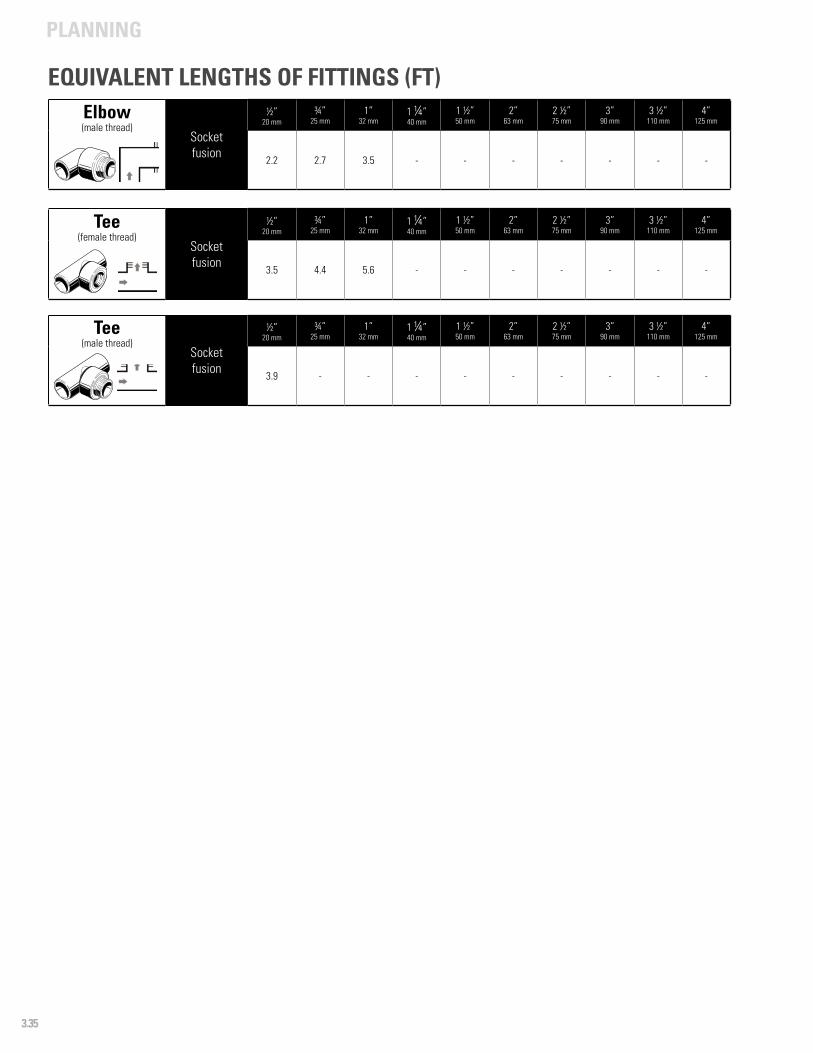
PLANNING
3.35
Tee(female thread)
Socketfusion
½”20 mm
¾”25 mm
1”32 mm
1 ¼”40 mm
1 ½”50 mm
2”63 mm
2 ½”75 mm
3”90 mm
3 ½”110 mm
4”125 mm
3.5 4.4 5.6 - - - - - - -
Tee(male thread)
Socketfusion
½”20 mm
¾”25 mm
1”32 mm
1 ¼”40 mm
1 ½”50 mm
2”63 mm
2 ½”75 mm
3”90 mm
3 ½”110 mm
4”125 mm
3.9 - - - - - - - - -
EQUIVALENT LENGTHS OF FITTINGS (FT)Elbow(male thread)
Socketfusion
½”20 mm
¾”25 mm
1”32 mm
1 ¼”40 mm
1 ½”50 mm
2”63 mm
2 ½”75 mm
3”90 mm
3 ½”110 mm
4”125 mm
2.2 2.7 3.5 - - - - - - -
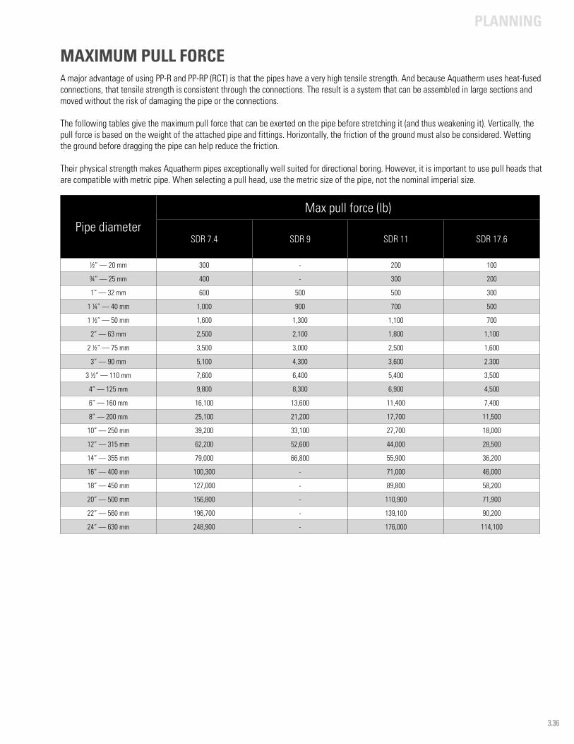
PLANNING
3.36
Pipe diameterMax pull force (lb)
SDR 7.4 SDR 9 SDR 11 SDR 17.6
½” — 20 mm 300 - 200 100
¾” — 25 mm 400 - 300 200
1” — 32 mm 600 500 500 300
1 ¼” — 40 mm 1,000 900 700 500
1 ½” — 50 mm 1,600 1,300 1,100 700
2” — 63 mm 2,500 2,100 1,800 1,100
2 ½” — 75 mm 3,500 3,000 2,500 1,600
3” — 90 mm 5,100 4,300 3,600 2.300
3 ½” — 110 mm 7,600 6,400 5,400 3,500
4“ — 125 mm 9,800 8,300 6,900 4,500
6” — 160 mm 16,100 13,600 11,400 7,400
8” — 200 mm 25,100 21,200 17,700 11,500
10” — 250 mm 39,200 33,100 27,700 18,000
12” — 315 mm 62,200 52,600 44,000 28,500
14” — 355 mm 79,000 66,800 55,900 36,200
16” — 400 mm 100,300 - 71,000 46,000
18” — 450 mm 127,000 - 89,800 58,200
20” — 500 mm 156,800 - 110,900 71,900
22” — 560 mm 196,700 - 139,100 90,200
24” — 630 mm 248,900 - 176,000 114,100
MAXIMUM PULL FORCEA major advantage of using PP-R and PP-RP (RCT) is that the pipes have a very high tensile strength. And because Aquatherm uses heat-fused connections, that tensile strength is consistent through the connections. The result is a system that can be assembled in large sections and moved without the risk of damaging the pipe or the connections.
The following tables give the maximum pull force that can be exerted on the pipe before stretching it (and thus weakening it). Vertically, the pull force is based on the weight of the attached pipe and fittings. Horizontally, the friction of the ground must also be considered. Wetting the ground before dragging the pipe can help reduce the friction.
Their physical strength makes Aquatherm pipes exceptionally well suited for directional boring. However, it is important to use pull heads that are compatible with metric pipe. When selecting a pull head, use the metric size of the pipe, not the nominal imperial size.


Heat fusion connections
Training and installation
Fusion techniques
Supporting the pipe
Linear expansion
Expansion controls
Fusion outlets
Transition fittings
Other considerations
Pressure test
4INSTALLATION PRINCIPLES
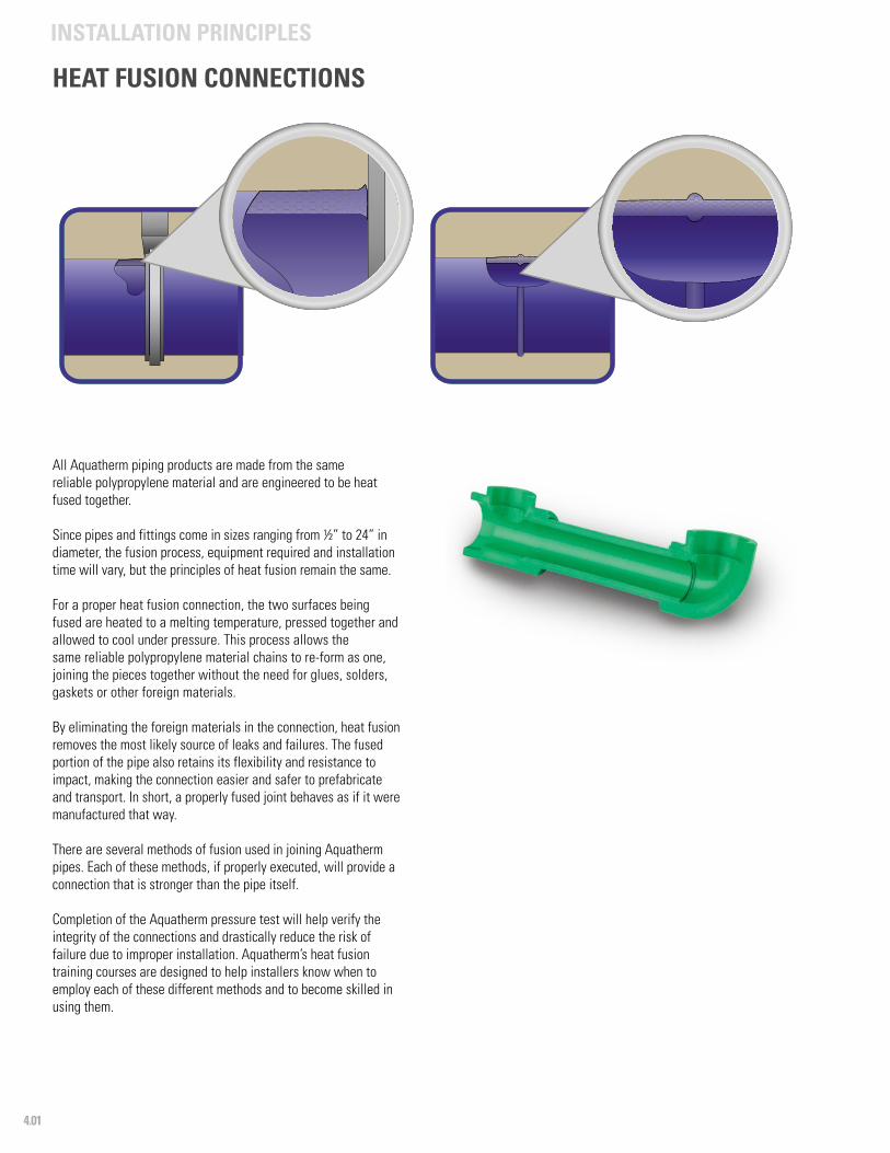
4.01
INSTALLATION PRINCIPLES
All Aquatherm piping products are made from the same reliable polypropylene material and are engineered to be heat fused together.
Since pipes and fittings come in sizes ranging from ½” to 24” in diameter, the fusion process, equipment required and installation time will vary, but the principles of heat fusion remain the same.
For a proper heat fusion connection, the two surfaces being fused are heated to a melting temperature, pressed together and allowed to cool under pressure. This process allows the same reliable polypropylene material chains to re-form as one, joining the pieces together without the need for glues, solders, gaskets or other foreign materials.
By eliminating the foreign materials in the connection, heat fusion removes the most likely source of leaks and failures. The fused portion of the pipe also retains its flexibility and resistance to impact, making the connection easier and safer to prefabricate and transport. In short, a properly fused joint behaves as if it were manufactured that way.
There are several methods of fusion used in joining Aquatherm pipes. Each of these methods, if properly executed, will provide a connection that is stronger than the pipe itself.
Completion of the Aquatherm pressure test will help verify the integrity of the connections and drastically reduce the risk of failure due to improper installation. Aquatherm’s heat fusion training courses are designed to help installers know when to employ each of these different methods and to become skilled in using them.
HEAT FUSION CONNECTIONS
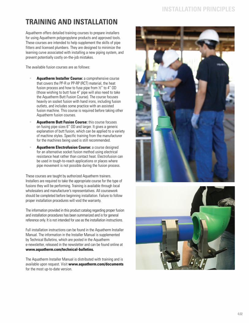
4.02
INSTALLATION PRINCIPLES
TRAINING AND INSTALLATIONAquatherm offers detailed training courses to prepare installers for using Aquatherm polypropylene products and approved tools. These courses are intended to help supplement the skills of pipe fitters and licensed plumbers. They are designed to minimize the learning curve associated with installing a new piping system, and prevent potentially costly on-the-job mistakes.
The available fusion courses are as follows:
• Aquatherm Installer Course: a comprehensive course that covers the PP-R or PP-RP (RCT) material, the heat fusion process and how to fuse pipe from ½” to 4” OD (those wishing to butt fuse 4“ pipe will also need to take the Aquatherm Butt Fusion Course). The course focuses heavily on socket fusion with hand irons, including fusion outlets, and includes some practice with an assisted fusion machine. This course is required before taking other Aquatherm fusion courses.
• Aquatherm Butt Fusion Course: this course focuses on fusing pipe sizes 6” OD and larger. It gives a generic explanation of butt fusion, which can be applied to a variety of machine styles. Specific training from the manufacturer for the machines being used is still recommended.
• Aquatherm Electrofusion Course: a course designed for an alternative socket fusion method using electrical resistance heat rather than contact heat. Electrofusion can be used in tough-to-reach applications or places where pipe movement is not possible during the fusion process.
These courses are taught by authorized Aquatherm trainers. Installers are required to take the appropriate course for the type of fusions they will be performing. Training is available through local wholesalers and manufacturer’s representatives. All coursework should be completed before beginning installation. Failure to follow proper installation procedures will void the warranty.
The information provided in this product catalog regarding proper fusion and installation procedures has been summarized and is for general reference only. It is not intended for use as the installation instructions.
Full installation instructions can be found in the Aquatherm Installer Manual. The information in the Installer Manual is supplemented by Technical Bulletins, which are posted in the Aquatherm e-newsletter, released in the newsletter and can be found online at www.aquatherm.com/technical-bulletins.
The Aquatherm Installer Manual is distributed with training and is available upon request. Visit www.aquatherm.com/documents for the most up-to-date version.
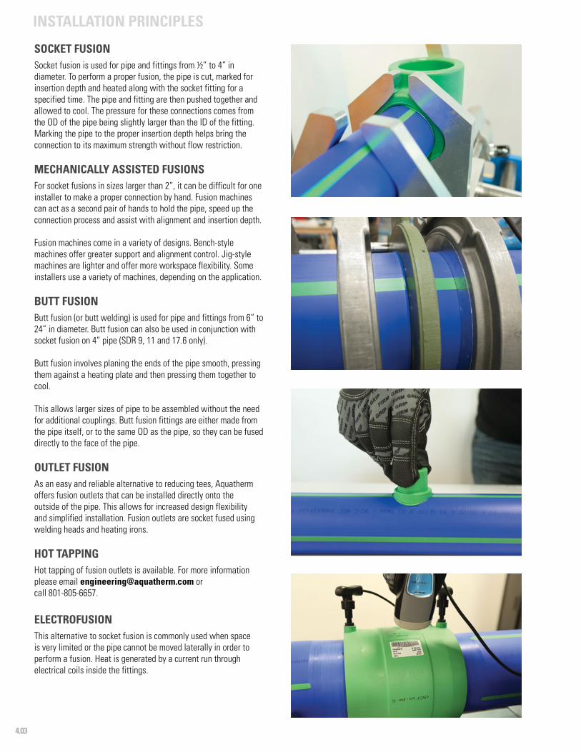
4.03
INSTALLATION PRINCIPLES
SOCKET FUSIONSocket fusion is used for pipe and fittings from ½” to 4” in diameter. To perform a proper fusion, the pipe is cut, marked for insertion depth and heated along with the socket fitting for a specified time. The pipe and fitting are then pushed together and allowed to cool. The pressure for these connections comes from the OD of the pipe being slightly larger than the ID of the fitting. Marking the pipe to the proper insertion depth helps bring the connection to its maximum strength without flow restriction.
MECHANICALLY ASSISTED FUSIONSFor socket fusions in sizes larger than 2”, it can be difficult for one installer to make a proper connection by hand. Fusion machines can act as a second pair of hands to hold the pipe, speed up the connection process and assist with alignment and insertion depth.
Fusion machines come in a variety of designs. Bench-style machines offer greater support and alignment control. Jig-style machines are lighter and offer more workspace flexibility. Some installers use a variety of machines, depending on the application.
BUTT FUSIONButt fusion (or butt welding) is used for pipe and fittings from 6” to 24” in diameter. Butt fusion can also be used in conjunction with socket fusion on 4” pipe (SDR 9, 11 and 17.6 only).
Butt fusion involves planing the ends of the pipe smooth, pressing them against a heating plate and then pressing them together to cool.
This allows larger sizes of pipe to be assembled without the need for additional couplings. Butt fusion fittings are either made from the pipe itself, or to the same OD as the pipe, so they can be fused directly to the face of the pipe.
OUTLET FUSIONAs an easy and reliable alternative to reducing tees, Aquatherm offers fusion outlets that can be installed directly onto the outside of the pipe. This allows for increased design flexibility and simplified installation. Fusion outlets are socket fused using welding heads and heating irons.
HOT TAPPINGHot tapping of fusion outlets is available. For more information please email [email protected] or call 801-805-6657.
ELECTROFUSIONThis alternative to socket fusion is commonly used when space is very limited or the pipe cannot be moved laterally in order to perform a fusion. Heat is generated by a current run through electrical coils inside the fittings.
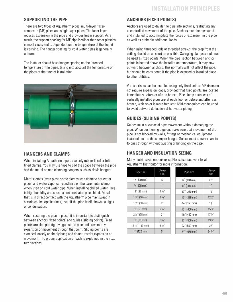
4.04
INSTALLATION PRINCIPLES
SUPPORTING THE PIPEThere are two types of Aquatherm pipes: multi-layer, faser-composite (MF) pipes and single-layer pipes. The faser layer reduces expansion in the pipe and provides linear support. As a result, the support spacing for MF pipe is wider than other plastics in most cases and is dependent on the temperature of the fluid it is carrying. The hanger spacing for cold water pipes is generally uniform.
The installer should base hanger spacing on the intended temperature of the pipes, taking into account the temperature of the pipes at the time of installation.
HANGERS AND CLAMPSWhen installing Aquatherm pipes, use only rubber-lined or felt-lined clamps. You may use tape to pad the space between the pipe and the metal on non-clamping hangers, such as clevis hangers.
Metal clamps (even plastic-safe clamps) can damage hot water pipes, and water vapor can condense on the bare metal clamp when used on cold water pipe. When installing chilled water lines in high-humidity areas, use a non-crushable pipe shield. Metal that is in direct contact with the Aquatherm pipe may sweat in certain chilled applications, even if the pipe itself shows no signs of condensation.
When securing the pipe in place, it is important to distinguish between anchors (fixed points) and guides (sliding points). Fixed points are clamped tightly against the pipe and prevent any expansion or movement through that point. Sliding points are clamped loosely or simply hung and do not restrict expansion or movement. The proper application of each is explained in the next two sections.
ANCHORS (FIXED POINTS)Anchors are used to divide the pipe into sections, restricting any uncontrolled movement of the pipe. Anchors must be measured and installed to accommodate the forces of expansion in the pipe as well as probable additional loads.
When using threaded rods or threaded screws, the drop from the ceiling should be as short as possible. Swinging clamps should not be used as fixed points. When the pipe section between anchor points is heated above the installation temperature, it may bow outward between anchors. This normally will not affect the pipe, but should be considered if the pipe is exposed or installed close to other utilities.
Vertical risers can be installed using only fixed points. MF risers do not require expansion loops, provided that fixed points are located immediately before or after a branch. Pipe clamp distances of vertically installed pipes are at each floor, or before and after each branch, whichever is more frequent. Mid-story guides can be used to avoid outward deflection of hot water piping.
GUIDES (SLIDING POINTS)Guides must allow axial pipe movement without damaging the pipe. When positioning a guide, make sure that movement of the pipe is not blocked by walls, fittings or mechanical equipment installed next to the clamp or hanger. Guides must allow expansion to pass through without twisting or binding on the pipe.
HANGER AND INSULATION SIZINGMany metric-sized options exist. Please contact your local Aquatherm Distributor for more information.
Pipe size Clampsize Pipe size Clamp
size
½” (20 mm) ¾” 6” (160 mm) 6 ½”
¾” (25 mm) 1” 8” (200 mm) 8”1” (32 mm) 1 ¼” 10” (250 mm) 10”
1 ¼” (40 mm) 1 ½” 12” (315 mm) 12 ½”
1 ½” (50 mm) 2” 14” (355 mm) 14”2” (63 mm) 2 ½” 16” (400 mm) 15 ¾”
2 ½” (75 mm) 3” 18” (450 mm) 17 ¾”
3” (90 mm) 3 ½” 20” (500 mm) 19 ¾”
3 ½” (110 mm) 4 ½” 22” (560 mm) 22”
4” (125 mm) 5” 24” (630 mm) 24 ¾”
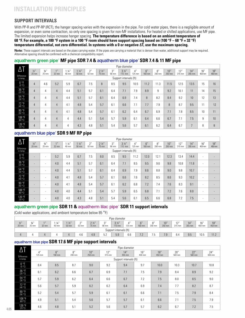
4.05
INSTALLATION PRINCIPLES
aquatherm green pipe SDR 11 & aquatherm lilac pipe® SDR 11 support intervals(Cold water applications, and ambient temperature below 85 °F)
Pipe diameter½”
20 mm¾”
25 mm1”
32 mm1 ¼”40 mm
1 ½”50 mm
2”63 mm
2 ½”75 mm
3”90 mm
3 ½”110 mm
4”125 mm
6”160 mm
8”200 mm
10”250 mm
12”315 mm
14”355 mm
16”400 mm
18”450 mm
Support intervals (ft)4 4 4 4 4 4.6 4.9 5.2 5.9 6.6 7.2 7.5 7.9 8.4 9.5 10.5 11.2
SUPPORT INTERVALSWith PP-R and PP-RP (RCT), the hanger spacing varies with the expansion in the pipe. For cold water pipes, there is a negligible amount of expansion, or even some contraction, so only one spacing is given for non-MF installations. For heated or chilled applications, use MF pipe. The limited expansion helps increase hanger spacing. The temperature difference is based on an ambient temperature of 68 °F. For example, a 100 °F system in a 100 °F room should have support spacing based on (100 °F – 68 °F = 32 °F) temperature differential, not zero differential. In systems with a 0 or negative ∆T, use the maximum spacing. Note: These support intervals are based on the pipes carrying water. If the pipes are carrying a material that is denser than water, additional support may be required. Alternative spacing should be confirmed with a chemical compatibility report.
∆T
Pipe diameter½”
20 mm¾”
25 mm1”
32 mm1 ¼”40 mm
1 ½” 50 mm
2” 63 mm
2 ½” 75 mm
3” 90 mm
3 ½” 110 mm
4” 125 mm
6” 160 mm
8” 200 mm
10” 250 mm
12” 315 mm
14” 355 mm
16”400 mm
18”450 mm
Difference in temp. Support intervals (ft)0 °F (0 °C) 4 4.6 5.2 5.9 6.7 7.5 8 8.5 9.5 10.5 11.2 11.3 11.5 12.5 13.5 15 16
36 °F (20 °C) 4 4 4 4.4 5.1 5.7 6.1 6.4 7.1 7.9 8.9 9 9.2 10.1 11 14 15
54 °F (30 °C) 4 4 4 4.4 5.1 5.7 6.1 6.4 6.9 7.4 8 8.2 8.4 9.2 10 12 13
72 °F (40 °C) 4 4 4 4.1 4.8 5.4 5.7 6.1 6.6 7.1 7.7 7.9 8 8.7 9.5 11 12
90 °F (50 °C) 4 4 4 4.1 4.8 5.4 5.7 6.1 6.2 6.4 6.7 6.9 7.1 7.8 8.5 10 11
108 °F (60 °C) 4 4 4 4 4.4 5.1 5.4 5.7 5.9 6.1 6.4 6.6 6.7 7.1 7.5 9 10
126 °F (70 °C) 4 4 4 4 4.3 4.8 5.1 5.4 5.6 5.7 6.1 6.2 6.4 6.7 7 8 8
∆T
Pipe diameter½”
20 mm¾”
25 mm1”
32 mm1 ¼”40 mm
1 ½” 50 mm
2” 63 mm
2 ½” 75 mm
3” 90 mm
3 ½” 110 mm
4” 125 mm
6” 160 mm
8” 200 mm
10” 250 mm
12” 315 mm
14” 355 mm
16”400 mm
18”450 mm
Difference in temp. Support intervals (ft)0 °F (0 °C) - - 5.2 5.9 6.7 7.5 8.0 8.5 9.5 11.2 12.0 12.1 12.3 13.4 14.4 - -
36 °F (20 °C) - - 4.0 4.4 5.1 5.7 6.1 6.4 7.1 8.5 9.5 9.6 9.8 10.8 11.8 - -
54 °F (30 °C) - - 4.0 4.4 5.1 5.7 6.1 6.4 6.9 7.9 8.6 8.8 9.0 9.8 10.7 - -
72 °F (40 °C) - - 4.0 4.1 4.8 5.4 5.7 6.1 6.6 7.6 8.2 8.5 8.6 9.3 10.2 - -
90 °F (50 °C) - - 4.0 4.1 4.8 5.4 5.7 6.1 6.2 6.8 7.2 7.4 7.6 8.3 9.1 - -
108 °F (60 °C) - - 4.0 4.0 4.4 5.1 5.4 5.7 5.9 6.5 6.8 7.1 7.2 7.6 8.0 - -
126 °F (70 °C) - - 4.0 4.0 4.3 4.8 5.1 5.4 5.6 6.1 6.5 6.6 6.8 7.2 7.5 - -
aquatherm blue pipe SDR 17.6 MF pipe support intervals
∆T Pipe diameter
4” 125 mm
6” 160 mm
8” 200 mm
10” 250 mm
12” 315 mm
14” 355 mm
16” 400 mm
18” 450 mm
20”500 mm
22”560 mm
24”630 mm
Difference in temp. Support intervals (ft)0 °F (0 °C) 8.4 8.5 8.7 9.0 9.2 9.4 9.7 10.0 10.3 10.7 10.8
36 °F (20 °C) 6.1 6.2 6.6 6.7 6.9 7.1 7.5 7.9 8.4 8.9 9.2
54 °F (30 °C) 5.7 5.9 6.2 6.4 6.6 6.7 7.2 7.5 8.0 8.5 9.0
72 °F (40 °C) 5.6 5.7 5.9 6.2 6.2 6.4 6.9 7.4 7.7 8.2 8.7
90 °F (50 °C) 5.2 5.4 5.7 5.9 6.1 6.1 6.6 7.1 7.5 7.9 8.4
108 °F (60 °C) 4.9 5.1 5.4 5.6 5.7 5.7 6.1 6.6 7.1 7.5 7.9
126 °F (70 °C) 4.6 4.8 5.1 5.2 5.6 5.7 5.7 6.2 6.7 7.2 7.5
aquatherm green pipe® MF pipe SDR 7.4 & aquatherm blue pipe® SDR 7.4 & 11 MF pipe
aquatherm blue pipe® SDR 9 MF RP pipe
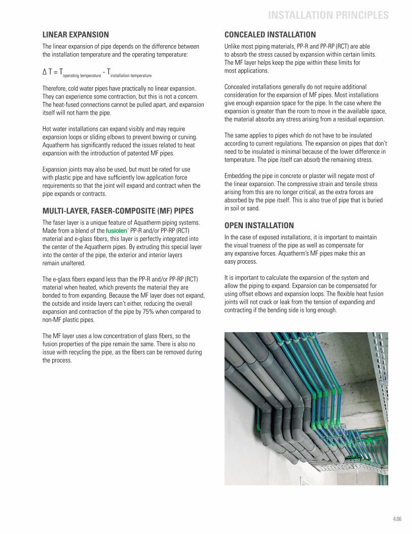
4.06
INSTALLATION PRINCIPLES
LINEAR EXPANSIONThe linear expansion of pipe depends on the difference between the installation temperature and the operating temperature:
∆ T = Toperating temperature - Tinstallation temperature
Therefore, cold water pipes have practically no linear expansion. They can experience some contraction, but this is not a concern. The heat-fused connections cannot be pulled apart, and expansion itself will not harm the pipe.
Hot water installations can expand visibly and may require expansion loops or sliding elbows to prevent bowing or curving. Aquatherm has significantly reduced the issues related to heat expansion with the introduction of patented MF pipes.
Expansion joints may also be used, but must be rated for use with plastic pipe and have sufficiently low application force requirements so that the joint will expand and contract when the pipe expands or contracts.
MULTI-LAYER, FASER-COMPOSITE (MF) PIPESThe faser layer is a unique feature of Aquatherm piping systems. Made from a blend of the fusiolen® PP-R and/or PP-RP (RCT) material and e-glass fibers, this layer is perfectly integrated into the center of the Aquatherm pipes. By extruding this special layer into the center of the pipe, the exterior and interior layers remain unaltered.
The e-glass fibers expand less than the PP-R and/or PP-RP (RCT) material when heated, which prevents the material they are bonded to from expanding. Because the MF layer does not expand, the outside and inside layers can’t either, reducing the overall expansion and contraction of the pipe by 75% when compared to non-MF plastic pipes.
The MF layer uses a low concentration of glass fibers, so the fusion properties of the pipe remain the same. There is also no issue with recycling the pipe, as the fibers can be removed during the process.
CONCEALED INSTALLATIONUnlike most piping materials, PP-R and PP-RP (RCT) are able to absorb the stress caused by expansion within certain limits. The MF layer helps keep the pipe within these limits for most applications.
Concealed installations generally do not require additional consideration for the expansion of MF pipes. Most installations give enough expansion space for the pipe. In the case where the expansion is greater than the room to move in the available space, the material absorbs any stress arising from a residual expansion.
The same applies to pipes which do not have to be insulated according to current regulations. The expansion on pipes that don’t need to be insulated is minimal because of the lower difference in temperature. The pipe itself can absorb the remaining stress.
Embedding the pipe in concrete or plaster will negate most of the linear expansion. The compressive strain and tensile stress arising from this are no longer critical, as the extra forces are absorbed by the pipe itself. This is also true of pipe that is buried in soil or sand.
OPEN INSTALLATIONIn the case of exposed installations, it is important to maintain the visual trueness of the pipe as well as compensate for any expansive forces. Aquatherm’s MF pipes make this an easy process.
It is important to calculate the expansion of the system and allow the piping to expand. Expansion can be compensated for using offset elbows and expansion loops. The flexible heat fusion joints will not crack or leak from the tension of expanding and contracting if the bending side is long enough.

4.07
INSTALLATION PRINCIPLES
CALCULATION OF LINEAR EXPANSIONThe coefficient (α) of linear expansion of Aquatherm MF pipes is comparable to the linear expansion of metal pipes and is only:
α MF = 0.035 mm/mK = 2.367 • 10-4 in/ft°F = 1.973 • 10-5 in/in°F
The coefficient of linear expansion of non-MF Aquatherm piping systems is comparable to other plastic pipes:
α non-MF= 0.150 mm/mK = 1.008•10-3 in/ft°F = 8.4 • 10-5 in/in°F
While Aquatherm MF pipes can absorb most of their own expansion stresses, this can cause the pipe to bow or bend. Fixed points should be installed at least every 120 feet, with some form of expansion control between each fixed point. The expansion control must be able to absorb the stress of all the expansion between the two fixed points.
Non-MF pipes used for hot applications should have expansion controls at every 30 feet for straight runs.
Risers of MF pipes may be installed rigidly without expansion compensation. The risers will need to be anchored at each floor. It is recommended to anchor near any branch lines to minimize vertical movement.
The following formula, calculation examples, data tables and diagrams help to determine the linear expansion. The difference between working temperature and maximum or minimum installation temperature is essential for the calculation of linear expansion.
CALCULATION OF LINEAR EXPANSIONCalculation example: Linear expansion
Given and required valuesSymbol Meaning Value Measuring unit
∆L Linear expansion ?in⁄ft °F
mm⁄m °K
α1 Coefficient of linear expansion
Aquatherm MF pipe
2.367•10 -4 in⁄ft °F
0.035 mm⁄m °K
α2
Coefficient of linear expansion Aquatherm non-MF pipe
1.008•10 -3 in⁄ft °F
0.15 mm⁄m °K
L Pipe length100 ft
30.5 m
TW Working temperature160 °F
71.0 °C
TM Installation temperature60 °F
15.6 °C
∆TTemperature difference between
working and installation temperature (∆T = TW – TM)
100 °F
38.0 °K
∆T [°F] • 5⁄9 = ∆T [°K]
The linear expansion ∆L is calculated according to the following formula:
∆L = α • L • ∆T
Material: Aquatherm MF pipe(α1 = 2.367 • 10-4 in/ft°F)
∆L = 2.367 • 10-4 • 100 ft • 100 °F
∆L = 2.4 in
Linear expansion comparison:Aquatherm MF versus standard PP pipe
0 1 2 3 4 5 6 7 8 9 10 110102030405060708090
100
Tem
pera
ture
diff
eren
ce ∆
T °F
Expansion ∆L in/ft
Faser-composite pipe Standard PP pipeMF pipe

4.08
INSTALLATION PRINCIPLES
LINEAR EXPANSION FOR AQUATHERM NON-MF PIPESThe linear expansion described on the preceding pages can be taken from the following tables and graphs.
Linear expansion ∆L (in):aquatherm non-MF pipe - α2= 0.150 mm⁄mK = 1.008•10-3 in/ft°F = 8.4 •10-5 in/in°F
Pipelength
Difference in temperature ∆T = Toperating temperature - Tinstallation temperature
10 °F 20 °F 30 °F 40 °F 50 °F 60 °F 80 °F 100 °F
Linear expansion ∆L (in)
10 ft 0.1 0.2 0.3 0.4 0.5 0.6 0.8 1.0
20 ft 0.2 0.4 0.6 0.8 1.0 1.2 1.6 2.0
30 ft 0.3 0.6 0.9 1.2 1.5 1.8 2.4 3.0
40 ft 0.4 0.8 1.2 1.6 2.0 2.4 3.2 4.0
50 ft 0.5 1.0 1.5 2.0 2.5 3.0 4.0 5.0
60 ft 0.6 1.2 1.8 2.4 3.0 3.6 4.8 6.0
70 ft 0.7 1.4 2.1 2.8 3.5 4.2 5.6 7.0
80 ft 0.8 1.6 2.4 3.2 4.0 4.8 6.4 8.0
90 ft 0.9 1.8 2.7 3.6 4.5 5.4 7.2 9.0
100 ft 1.0 2.0 3.0 4.0 5.0 6.0 8.0 10.0
150 ft 1.5 3.0 4.5 6.0 7.5 9.0 12.0 14.9
200 ft 2.0 4.0 6.0 8.0 10.0 12.0 15.9 19.9
aquatherm green pipe® and aquatherm lilac pipe® (non-MF)
Difference in temperature ∆T (°F)
30”
25”
20”
15”
10”
5”
0”
18°F 36°F 54°F 72°F 90°F 108°F 126°F 144°F
200 ft
180 ft
160 ft
140 ft
120 ft
100 ft
80 ft
60 ft
40 ft
20 ft
Fusiotherm¨-pipe
Difference in temperature ∆ [ °F]
pipe
leng
th L
0°F
linea
r exp
ansi
on (i
n)
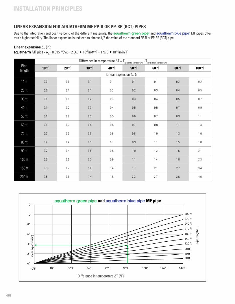
4.09
INSTALLATION PRINCIPLES
LINEAR EXPANSION FOR AQUATHERM MF PP-R OR PP-RP (RCT) PIPESDue to the integration and positive bond of the different materials, the aquatherm green pipe® and aquatherm blue pipe® MF pipes offer much higher stability. The linear expansion is reduced to almost 1/5 the value of the standard PP-R or PP-RP (RCT) pipe.
Linear expansion ∆L (in):aquatherm MF pipe - α1= 0.035 mm⁄mK = 2.367 • 10-4 in/ft°F = 1.973 • 10-5 in/in°F
Pipelength
Difference in temperature ∆T = Toperating temperature - Tinstallation temperature
10 °F 20 °F 30 °F 40 °F 50 °F 60 °F 80 °F 100 °F
Linear expansion ∆L (in)
10 ft 0.0 0.0 0.1 0.1 0.1 0.1 0.2 0.2
20 ft 0.0 0.1 0.1 0.2 0.2 0.3 0.4 0.5
30 ft 0.1 0.1 0.2 0.3 0.3 0.4 0.5 0.7
40 ft 0.1 0.2 0.3 0.4 0.5 0.5 0.7 0.9
50 ft 0.1 0.2 0.3 0.5 0.6 0.7 0.9 1.1
60 ft 0.1 0.3 0.4 0.5 0.7 0.8 1.1 1.4
70 ft 0.2 0.3 0.5 0.6 0.8 1.0 1.3 1.6
80 ft 0.2 0.4 0.5 0.7 0.9 1.1 1.5 1.8
90 ft 0.2 0.4 0.6 0.8 1.0 1.2 1.6 2.1
100 ft 0.2 0.5 0.7 0.9 1.1 1.4 1.8 2.3
150 ft 0.3 0.7 1.0 1.4 1.7 2.1 2.7 3.4
200 ft 0.5 0.9 1.4 1.8 2.3 2.7 3.6 4.6
aquatherm green pipe and aquatherm blue pipe MF pipe
Difference in temperature ∆T (°F)
12”
10”
8”
6”
4”
2”
0”
18°F 36°F 54°F 72°F 90°F 108°F 126°F 144°F
300 ft
270 ft
240 ft
210 ft
180 ft
150 ft
120 ft
90 ft
60 ft30 ft
Fusiotherm¨-faser composite pipe
Difference in temperature ∆ [ F]
pipe
leng
th L
0°F
linea
r exp
ansi
on (i
n)

4.10
INSTALLATION PRINCIPLES
EXPANSION CONTROLSLinear expansion from the temperature difference between operating temperature and installation temperature can be addressed with the controls shown here.
Aquatherm also provides a simplified tool to calculate expansion controls online at www.aquatherm.com/expansion-controls.
BENDING SIDEIn most cases, directional changes can be used to compensate for linear expansion in pipes. The values of the bending side can be determined using the following tables and diagrams.
Symbol Meaning
LBS Length of the bending side (in) (mm)
K Material-specific constant 2.98* 15
d Outside diameter (mm) (mm)
∆L Linear expansion (in) (mm)
L Pipe Length (ft) (m)
FP Fixed point
SP Sliding point*Includes metric to imperial conversion factor
Calculation of the bending side length:
LBS = K • √ d • ∆L
EXPANSION LOOPIf the linear expansion cannot be compensated for by a change in direction, it may be necessary to install an expansion loop.
In addition to the length of the bending side LBS, the width of the pipe bend Amin must be considered.
Symbol Meaning
Amin Width of the expansion loop (in)
SD Safety distance 6 in
The pipe bend Amin is calculated according to the following formula: Amin = 2 • ∆L + SD
For example, with ∆L = 1.4 in the width of the expansion loop should be at least (2 • 1.4) + 6 = 8.8 in
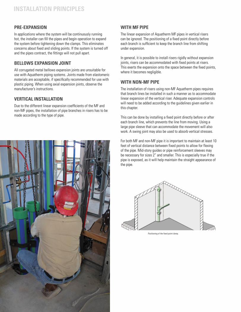
4.11
INSTALLATION PRINCIPLES
Positioning of the fixed point clamp.
PRE-EXPANSIONIn applications where the system will be continuously running hot, the installer can fill the pipes and begin operation to expand the system before tightening down the clamps. This eliminates concerns about fixed and sliding points. If the system is turned off and the pipes contract, the fittings will not pull apart.
BELLOWS EXPANSION JOINTAll corrugated metal bellows expansion joints are unsuitable for use with Aquatherm piping systems. Joints made from elastomeric materials are acceptable, if specifically recommended for use with plastic piping. When using axial expansion joints, observe the manufacturer’s instructions.
VERTICAL INSTALLATIONDue to the different linear expansion coefficients of the MF and non-MF pipes, the installation of pipe branches in risers has to be made according to the type of pipe.
WITH MF PIPEThe linear expansion of Aquatherm MF pipes in vertical risers can be ignored. The positioning of a fixed point directly before each branch is sufficient to keep the branch line from shifting under expansion.
In general, it is possible to install risers rigidly without expansion joints, risers can be accommodated with fixed points at risers. This exerts the expansion onto the space between the fixed points, where it becomes negligible.
WITH NON-MF PIPEThe installation of risers using non-MF Aquatherm pipes requires that branch lines be installed in such a manner as to accommodate linear expansion of the vertical riser. Adequate expansion controls will need to be added according to the guidelines given earlier in this chapter.
This can be done by installing a fixed point directly before or after each branch line, which prevents the line from moving. Using a large pipe sleeve that can accommodate the movement will also work. A swing joint may also be used to absorb vertical stresses.
For both MF and non-MF pipe it is important to maintain at least 10 feet of vertical distance between fixed points to allow for flexing of the pipe. Mid-story guides or pipe reinforcement sleeves may be necessary for sizes 2” and smaller. This is especially true if the pipe is exposed, as it will help maintain the straight appearance of the pipe.
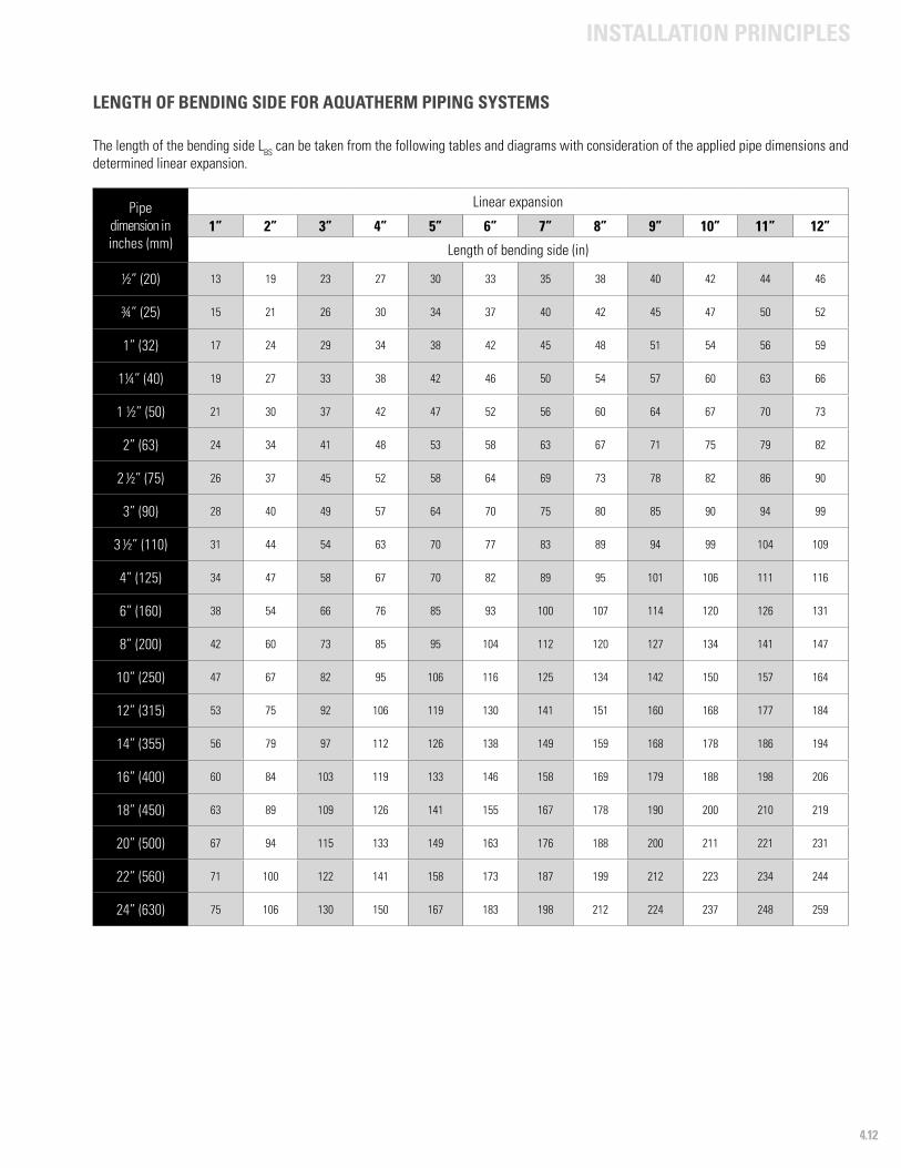
4.12
INSTALLATION PRINCIPLES
LENGTH OF BENDING SIDE FOR AQUATHERM PIPING SYSTEMS
The length of the bending side LBS can be taken from the following tables and diagrams with consideration of the applied pipe dimensions and determined linear expansion.
Pipe dimension in inches (mm)
Linear expansion
1” 2” 3” 4” 5” 6” 7” 8” 9” 10” 11” 12”
Length of bending side (in)
½” (20) 13 19 23 27 30 33 35 38 40 42 44 46
¾” (25) 15 21 26 30 34 37 40 42 45 47 50 52
1” (32) 17 24 29 34 38 42 45 48 51 54 56 59
1¼” (40) 19 27 33 38 42 46 50 54 57 60 63 66
1 ½” (50) 21 30 37 42 47 52 56 60 64 67 70 73
2” (63) 24 34 41 48 53 58 63 67 71 75 79 82
2 ½” (75) 26 37 45 52 58 64 69 73 78 82 86 90
3” (90) 28 40 49 57 64 70 75 80 85 90 94 99
3 ½” (110) 31 44 54 63 70 77 83 89 94 99 104 109
4” (125) 34 47 58 67 70 82 89 95 101 106 111 116
6” (160) 38 54 66 76 85 93 100 107 114 120 126 131
8” (200) 42 60 73 85 95 104 112 120 127 134 141 147
10” (250) 47 67 82 95 106 116 125 134 142 150 157 164
12” (315) 53 75 92 106 119 130 141 151 160 168 177 184
14” (355) 56 79 97 112 126 138 149 159 168 178 186 194
16” (400) 60 84 103 119 133 146 158 169 179 188 198 206
18” (450) 63 89 109 126 141 155 167 178 190 200 210 219
20” (500) 67 94 115 133 149 163 176 188 200 211 221 231
22” (560) 71 100 122 141 158 173 187 199 212 223 234 244
24” (630) 75 106 130 150 167 183 198 212 224 237 248 259

4.13
INSTALLATION PRINCIPLES
FUSION OUTLETS
Pipe sizeThread size
½” ¾” 1”
1 ¼” (40 mm) MPP/FPP MPP/FPP
1 ½” (50 mm) MPP/FPP MPP/FPP
2” (63 mm) MPP/FPP MPP/FPP
2 ½” (75 mm) MPP/FPP MPP/FPP F
3” (90 mm) MPP/FPP MPP/FPP F
3 ½” (110 mm) MPP/FPP MPP/FPP F
4” (125 mm) MPP/FPP MPP/FPP F
6” (160 mm) MPP/FPP MPP/FPP F
8” (200 mm) F F F
10” (250 mm) F F F
BRANCHING OPTIONS
FUSION OUTLETS WITHTHREADED TRANSITIONS
For installations with branch lines, fusion outlets offer many advantages over traditional reducing tees. Fusion outlets are installed directly onto the side of the pipe and can be added after the main lines are already in place. Fusion outlets also generate less friction than a reducing tee, lowering the pressure loss of the entire system.
Fusion outlets are installed by drilling out a properly sized hole and then fusing the fitting in place using socket fusion tools. The drilling bores offered by Aquatherm will produce properly sized holes, but the bits larger than 2” require a drill press to operate.
M = male thread available, F = female thread available
Pipe size Outlets available
1 ¼” (40 mm) ½” (20 mm) — ¾” (25 mm)
1 ½” (50 mm) ½” (20 mm) — ¾” (25 mm)
2” (63 mm) ½” (20 mm) — 1” (32 mm)
2 ½” (75 mm) ½” (20 mm) — 1 ¼” (40 mm)
3” (90 mm) ½” (20 mm) — 1 ¼” (40 mm)
3 ½” (110 mm) ½” (20 mm) — 1 ½” (50 mm)
4” (125 mm) ½” (20 mm) — 2” (63 mm)
6” (160 mm) ½” (20 mm) — 3” (90 mm)
8” (200 mm) ½” (20 mm) — 4” (125 mm)
10” (250 mm) ½” (20 mm) — 4” (125 mm)
12” (315 mm) 2” (63 mm) — 6” (160 mm)
14” (355 mm) 2” (63 mm) — 8” (200 mm)
16” (400 mm) 2” (63 mm) — 10” (250 mm)
18” (450 mm) 2 ½” (75 mm) — 12” (315 mm)
20” (500 mm) 2 ½” (75 mm) — 12” (315 mm)
22” (560 mm) 2 ½” (75 mm) — 12” (315 mm)
24” (630 mm) 2 ½” (75 mm) — 12” (315 mm)
Bores produced by other companies must be at least 1 mm smaller than the intended branch, and should be no more than 3 mm smaller.
The table below can help determine if a fusion outlet is available for a particular branch size. The table below helps determine if a threaded outlet is available for a particular branch size.
When making a threaded connection using an Aquatherm threaded adapter fitting (FPT) and metal threaded pipe or other component, the threaded component or pipe should only be tightened 1-2 turns beyond hand-tight. The threads should NOT bottom out in the FPT fitting. It is recommended that only PTFE pipe tape be used on the threads as pipe dope may allow the threads to be engaged beyond recommended limits.
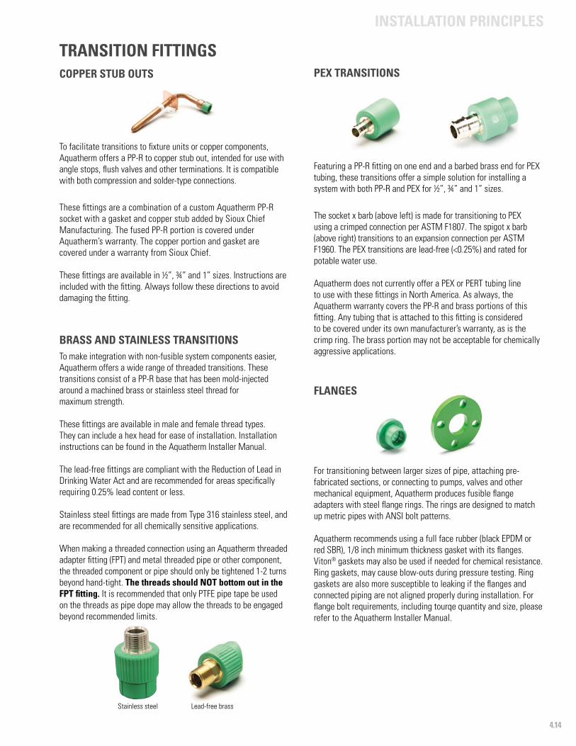
4.14
INSTALLATION PRINCIPLES
COPPER STUB OUTS
To facilitate transitions to fixture units or copper components, Aquatherm offers a PP-R to copper stub out, intended for use with angle stops, flush valves and other terminations. It is compatible with both compression and solder-type connections.
These fittings are a combination of a custom Aquatherm PP-R socket with a gasket and copper stub added by Sioux Chief Manufacturing. The fused PP-R portion is covered under Aquatherm’s warranty. The copper portion and gasket are covered under a warranty from Sioux Chief.
These fittings are available in ½”, ¾” and 1” sizes. Instructions are included with the fitting. Always follow these directions to avoid damaging the fitting.
Featuring a PP-R fitting on one end and a barbed brass end for PEX tubing, these transitions offer a simple solution for installing a system with both PP-R and PEX for ½”, ¾” and 1” sizes.
The socket x barb (above left) is made for transitioning to PEX using a crimped connection per ASTM F1807. The spigot x barb (above right) transitions to an expansion connection per ASTM F1960. The PEX transitions are lead-free (<0.25%) and rated for potable water use.
Aquatherm does not currently offer a PEX or PERT tubing line to use with these fittings in North America. As always, the Aquatherm warranty covers the PP-R and brass portions of this fitting. Any tubing that is attached to this fitting is considered to be covered under its own manufacturer’s warranty, as is the crimp ring. The brass portion may not be acceptable for chemically aggressive applications.
TRANSITION FITTINGS
BRASS AND STAINLESS TRANSITIONS To make integration with non-fusible system components easier, Aquatherm offers a wide range of threaded transitions. These transitions consist of a PP-R base that has been mold-injected around a machined brass or stainless steel thread for maximum strength.
These fittings are available in male and female thread types. They can include a hex head for ease of installation. Installation instructions can be found in the Aquatherm Installer Manual.
The lead-free fittings are compliant with the Reduction of Lead in Drinking Water Act and are recommended for areas specifically requiring 0.25% lead content or less.
Stainless steel fittings are made from Type 316 stainless steel, and are recommended for all chemically sensitive applications.
When making a threaded connection using an Aquatherm threaded adapter fitting (FPT) and metal threaded pipe or other component, the threaded component or pipe should only be tightened 1-2 turns beyond hand-tight. The threads should NOT bottom out in the FPT fitting. It is recommended that only PTFE pipe tape be used on the threads as pipe dope may allow the threads to be engaged beyond recommended limits.
For transitioning between larger sizes of pipe, attaching pre-fabricated sections, or connecting to pumps, valves and other mechanical equipment, Aquatherm produces fusible flange adapters with steel flange rings. The rings are designed to match up metric pipes with ANSI bolt patterns.
Aquatherm recommends using a full face rubber (black EPDM or red SBR), 1/8 inch minimum thickness gasket with its flanges. Viton® gaskets may also be used if needed for chemical resistance. Ring gaskets, may cause blow-outs during pressure testing. Ring gaskets are also more susceptible to leaking if the flanges and connected piping are not aligned properly during installation. For flange bolt requirements, including tourqe quantity and size, please refer to the Aquatherm Installer Manual.
Stainless steel Lead-free brass
FLANGES
PEX TRANSITIONS
4.15
INSTALLATION PRINCIPLES
FLUSHING THE PIPESAll piping systems, regardless of their intended medium, should be flushed thoroughly after installation. The following concerns should be addressed before the installation can be put into service:
• Protection of the water quality• Avoidance of corrosion damage• Avoidance of malfunctions of pumps and equipment• Cleanliness of the inner surface of the pipe
These requirements can be met by:
• Flushing the system with water• Flushing the system with a mixture of air and water
The flushing medium may be determined by local codes, engineering specifications or the needs of the mechanical equipment used.
If a flushing fluid other than water, or mixed with water, is used, ensure that the fluid is compatible with the Aquatherm piping or contact [email protected] for evaluation.
Where no requirements are established, potable water is sufficient for flushing Aquatherm piping materials.
UV PROTECTIONIn applications where the installed pipe will be exposed to UV radiation (such as outdoor applications), it is recommended that Aquatherm UV pipe be used. This pipe is engineered with an outer coating of black polyethylene that protects the pipe from the aging and discoloration that can occur from prolonged exposure to UV radiation. This coating must be removed at the points of connection prior to heat fusion. Detailed instructions can be found in the Installer Manual.
Aquatherm pipes come from the factory packed in UV-resistant bags, which protect the pipes until they are removed. All Aquatherm pipes and fittings have UV stabilizers to bridge transport and installation times. Maximum recommended storage time exposed to UV radiation is six months.
Plastic-safe paint can be used to protect the pipe from UV damage, but most paints will not adhere well to PP-R and PP-RP (RCT). Painted pipe may need to be re-coated or maintained, and this is the responsibility of the installer or owner. Aquatherm recommends using an elastomeric paint, which will expand and contract with the pipes, but does not endorse any particular brand of paint. The pipe may also be painted for reasons unrelated to UV protection, if needed.
Painting the pipe is considered an aftermarket modification to the Aquatherm pipe, so Aquatherm does not assume any responsibility for the performance of the paint. Always use a paint that is safe with PP-R and PP-RP (RCT). Damage caused by painting is not covered under the Aquatherm warranty.
FREEZE PROTECTIONAquatherm piping systems may be installed in applications where temperatures may get below freezing (32°F).
The Aquatherm piping is considered “freeze-tolerant,” meaning that freezing the piping with water in it will not normally cause the pipe to rupture, provided the pipe can expand with the water. However, the piping is not intended to be installed where freeze/thaw will occur, as this can damage the pipe or other components in the system.
To avoid this, antifreeze (glycerin or glycol solutions at any concentration allowed by local codes) or heating cables (heat tracing) applied externally or inside the pipe may be used to ensure that the system does not freeze. Alternatively, providing a means for a minimum constant flow even during power outages can prevent freezing.
Regardless of the method chosen, all products must be used in accordance with the freeze protection system manufacturer’s recommendations, the product listings, and in compliance with all applicable local codes.
When using any type of external heat source applied to the piping, such as heat tape or heating cables, the product must be suitable for use with plastic piping. Additionally, the heat system must be self-regulating and ensure the surface temperature of the Aquatherm pipe and fittings will not exceed 160 °F (71 °C).
GROUNDINGMost building codes require that grounding be provided for all conductive components inside the structure. It is important to note that Aquatherm pipes do not carry electrical currents and cannot be used to provide grounding. Where metal pipes are replaced by PP-R and PP-RP (RCT) pipes, the ground cannot be created by the piping system. An alternative ground system must be installed. The grounding system should be inspected by a qualified electrician.
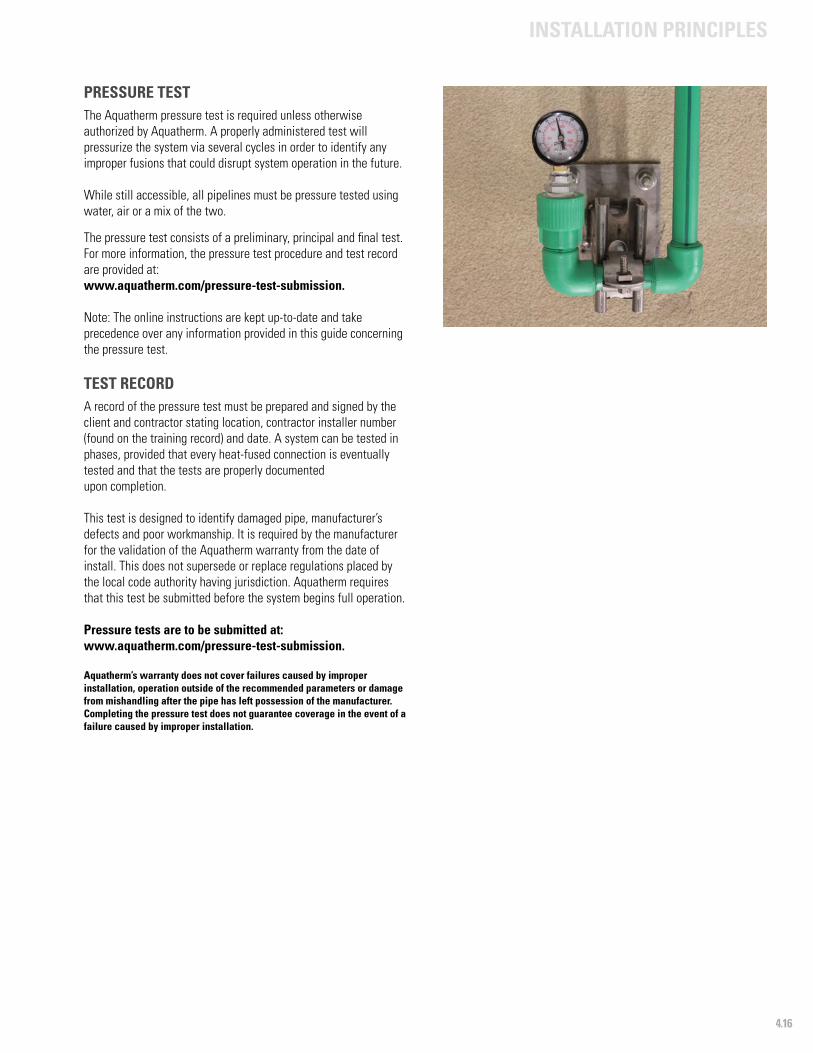
4.16
INSTALLATION PRINCIPLES
PRESSURE TEST The Aquatherm pressure test is required unless otherwise authorized by Aquatherm. A properly administered test will pressurize the system via several cycles in order to identify any improper fusions that could disrupt system operation in the future.
While still accessible, all pipelines must be pressure tested using water, air or a mix of the two.
The pressure test consists of a preliminary, principal and final test. For more information, the pressure test procedure and test record are provided at: www.aquatherm.com/pressure-test-submission.
Note: The online instructions are kept up-to-date and take precedence over any information provided in this guide concerning the pressure test.
TEST RECORDA record of the pressure test must be prepared and signed by the client and contractor stating location, contractor installer number (found on the training record) and date. A system can be tested in phases, provided that every heat-fused connection is eventually tested and that the tests are properly documented upon completion.
This test is designed to identify damaged pipe, manufacturer’s defects and poor workmanship. It is required by the manufacturer for the validation of the Aquatherm warranty from the date of install. This does not supersede or replace regulations placed by the local code authority having jurisdiction. Aquatherm requires that this test be submitted before the system begins full operation.
Pressure tests are to be submitted at: www.aquatherm.com/pressure-test-submission.
Aquatherm’s warranty does not cover failures caused by improper installation, operation outside of the recommended parameters or damage from mishandling after the pipe has left possession of the manufacturer. Completing the pressure test does not guarantee coverage in the event of a failure caused by improper installation.

825 West 600 NorthLindon, UT 84042USAPhone: +1 801-805-6657
HeadquartersBiggen 557439 AttendornGermanyPhone: +49 (0) 2722 950-0www.aquatherm.de
NSF®Edition 04/18 Printed in the USA
P
ip e S y s te
ms
MADE IN GERMAN
Y
© 2018 aquatherm GmbH, aquatherm LP, and aquatherm Corp.All rights reserved.