aqua logic programming flow chart aqua logic · introduction before you begin what’s included...
TRANSCRIPT

Aqua Logic Programming Flow Chart
North Kingstown, RI 02852 USA092028J
Copyright © 2008 Goldine Controls
www.goldlinecontrols.com 888-921-7665
Aqua LogicAqua LogicAqua LogicAqua LogicAqua LogicAutomation and Chlorination
Installation Manualfor model
AQL-P-4
(actuators, cell & remote display not included - order separately)
denotes conditional items
PS-4 only
PS-4 only
LDC
G LINEON TROLS
LDC
G LINEON TROLS

IMPORTANT SAFETY INSTRUCTIONS
When using this electrical equipment, basic safety precautions should always befollowed, including the following:
• READ AND FOLLOW ALL INSTRUCTIONS
• ! WARNING: Disconnect all AC power during installation.
• ! WARNING: Water in excess of 100 degrees Fahrenheit may behazardous to your health.
• ! WARNING: To reduce the risk of injury, do not permit children touse this product unless they are closely supervised at all times.
• A green colored terminal marked “Earth Ground” is located inside the wiringcompartment. To reduce the risk of electric shock, this terminal must beconnected to the grounding means provided in the electric supply servicepanel with a continuous copper wire equivalent in size to the circuit conductorssupplying the equipment.
• One bonding lug for US models (two for Canadian models) is provided on theexternal surface. To reduce the risk of electric shock, connect the localcommon bonding grid in the area of the swimming pool, spa, or hot tub tothese terminals with an insulated or bare copper conductor not smaller than 8AWG US / 6 AWG Canada.
• All field installed metal components such as rails, ladders, drains, or othersimilar hardware within 3 meters of the pool, spa or hot tub shall be bonded tothe equipment grounding bus with copper conductors not smaller than 8 AWGUS / 6 AWG Canada.
• SAVE THESE INSTRUCTIONS32
LIMITED WARRANTY Goldline warrants its Aqua Rite, Aqua Rite Pro, Aqua Trol, Aqua Logic and Pro Logic products(products with Goldline part numbers starting with AQ-RITE-, AQ-RT-PRO, AQ-TROL-, AQ-LOGIC-, AQL-P-, AQL-PS-,AQL-CL-, PL-P-, PL-PS-, and HPC-2) to be free from defects in material or workmanship, under normal use and service:
For three years from the date of the initial system installation on private, residential swimming pools within the USA or Canadaand one year from the date of initial system installation on commercial installations, installations outside of the USA or Canadaand for any replacement parts or accessory products, provided they are installed in accordance with the Goldline installationinstructions and specifications provided with the product. If written proof of the date of the initial system installation is notprovided to Goldline, the manufacturing datecode on the Aqua Rite, Aqua Rite Pro, Aqua Trol, Aqua Logic and Pro Logicelectronics unit will be the sole determinant of the date of the initial system installation.
For residential installations in USA or Canada: If a product is defective in workmanship or materials and is removed and returnedfreight prepaid within three (3) years after the date of the initial system installation, Goldline will, at its option, either repair orreplace the defective product and return it freight prepaid.
For commercial installations, installations outside the USA and Canada, and accessory products and replacement parts: If aproduct is defective in workmanship or materials and is removed and returned freight prepaid within one (1) year after the dateof the initial system installation, Goldline will, at its option, either repair or replace the defective product and return it freightprepaid.
Contact any Goldline dealer or contact Goldline at 61 Whitecap Drive, North Kingstown, RI 02852 for warranty service. Thecosts incurred in removal and/or reinstallation of the product are NOT covered under this warranty. Some states do not allowlimitations on how long an implied warranty lasts, so the above limitation may not apply to you.
WARRANTY EXCLUSIONS:1. Material supplied or workmanship performed by others in process of installation.
2. Damage resulting from improper installation including installation on pools larger than the product rating.
3. Problems resulting from failure to operate the product(s) in accordance with the recommended instructions containedin product’s owners manual(s).
4. Problems resulting from failure to maintain pool water chemistry in accordance with the recommendations in theowners manual(s).
5. Problems resulting from tampering, accident, abuse, negligence, unauthorized repairs or alternations, fire, flood,lightning, freezing, external water, degradation of natural stone used in or immediately adjacent to a pool or spa, waror acts of God.
DISCLAIMER. THE EXPRESS LIMITED WARRANTY ABOVE CONSTITUTES THE ENTIRE WARRANTY OFGOLDLINE WITH RESPECT TO ITS POOL AUTOMATION AND CHLORINATION PRODUCTS AND IS IN LIEUOF ALL OTHER WARRANTIES, EXPRESSED OR IMPLIED, INCLUDING WARRANTIES OF MERCHANTABILITYOR FITNESS FOR A PARTICULAR PURPOSE. THIS WARRANTY GIVES YOU SPECIFIC LEGAL RIGHTS, ANDYOU MAY ALSO HAVE OTHER RIGHTS WHICH VARY FROM STATE TO STATE. IN NO EVENT SHALL GOLDLINEBE RESPONSIBLE FOR ANY CONSEQUENTIAL, SPECIAL OR INCIDENTAL DAMAGES OF ANY NATUREWHATSOEVER, INCLUDING, BUT NOT LIMITED TO, PERSONAL INJURY, PROPERTY DAMAGE, DAMAGE TOOR LOSS OF EQUIPMENT, LOST PROFITS OR REVENUE, COSTS OF RENTING REPLACEMENTS, AND OTHERADDITIONAL EXPENSES, EVEN IF THE SELLER HAD BEEN ADVISED OF THE POSSIBILITY OF SUCHDAMAGES. SOME STATES DO NOT ALLOW THE EXCLUSION OF LIMITATION OF INCIDENTAL ORCONSEQUENTIAL DAMAGES, SO THE ABOVE LIMITATION OR EXCLUSION MAY NOT APPLY TO YOU.
NO WHOLESALER, AGENT, DEALER, CONTRACTOR OR OTHER PERSON IS AUTHORIZED TO GIVE ANYWARRANTY ON BEHALF OF GOLDLINE.
THIS WARRANTY IS VOID IF THE PRODUCT HAS BEEN ALTERED IN ANY WAY AFTER LEAVING THE FACTORY.

Table of Contents
Introduction Before You Begin................................................................... 1Installation Steps.................................................................... 2
1. Preparing General Water Chemistry..................................................... 3 Pool/Spa Water Salt.......................................................................................... 4
2. Mounting Aqua Logic Control Center................................................... 6 Equipment Temperature Sensors........................................................... 6
Optional AQL-CL Chlorination Kit........................................ 6Optional Remote Controls.................................................... 6Optional Valve Actuators....................................................... 7
3. Plumbing Pool/Spa Configuration........................................................ 8Turbo Cell............................................................................... 9Flow Switch............................................................................ 9
4. Electrical Main Service.......................................................................... 10 Wiring Grounding and Bonding........................................................ 10
Circuit Breaker Installation and Wiring......................... ...... 10General Purpose Outlet........................................................ 11Aqua Logic Control Power................................................... 11High Voltage Pool Equipment.............................................. 12Low Voltage Wiring............................................................... 13
5. Configuration Configuration Menu............................................................... 19
6. System Startup Before Startup...................................................................... 28 and Checkout Heater Checkout................................................................... 28
Service Mode........................................................................ 29
7. Warranty Aqua Logic Limited Warranty.............................................. 32
31

Introduction
Before You BeginWhat’s IncludedBefore attempting to install the Aqua Logic system, check that the following components have beenincluded in the package:
Aqua Logic Electronics Unit (3) Temperature sensors with 15 ft. (5m) cable, hose clamp
What’s NOT IncludedSome of the additional items that you may need to complete an installation include:
Circuit breakersNone are included with control—see page 10 and inside of door for suitable breakers
Wire4-conductor cable (electronics unit to remote display/keypad)Wire/conduit for 100A service from main panel to Aqua LogicWire/conduit for filter pump and other high voltage loadsWire for bonding
MiscellaneousUtility electrical outlet and weatherproof cover (for mounting on side of Aqua Logic)Mounting hardware (screws, etc.) for mounting Aqua Logic and remote display/keypadValves (use standard Hayward, Pentair/Compool, or Jandy valves)Additional valve actuators
Accessory Products - Order SeparatelyAQL-CL Chlorination kitAQL-CL-25FT Chlorination kit with 25ft cableAQL-WW-P-4 Wired Remote Display (requires AQL-BASE-RF)AQL-SS-6B-x (x=W/G/B) Wired Spa Side 6 Function Remote Control, 150ft cable, specify color (white, gray or black)AQL2-POD Handheld Wireless Waterproof Remote with Charging Station (requires AQL2-BASE-RF)AQL-SS-RF Wireless Spa Side Remote Control (AQL-BASE-RF required)AQL-BASE-RF Base ReceiverAQL2-BASE-RF Base ReceiverAQL-DIM Light Dimmer RelayGVA-24 Valve ActuatorV&A-xx Valve & Actuator (xx=1P (1.5” pos. seal), -2P (2” pos. seal)
NOTE: Before installing this product as part of a saline water purification system in a pool or spa usingnatural stone for coping or for immediately adjacent patios/decking, a qualified stone installation specialistshould be consulted regarding the appropriate type, installation, sealant (if any) and maintenance of stoneused around a saline pool with electronic chlorine generator in your particular location and circumstances.
1 30
The following statement is applicable if any of the wireless accessories are connected to the Aqua Logicsystem.
FCC Statement(Compliance Statement, Part 15.19): This device complies with Part 15 of the FCC Rules. Operation issubject to the following two conditions: (1) This device may not cause harmful interference, and (2) thisdevice must accept any interference received, including interference that may cause undesired operation.
WARNING (Part 15.21): Changes or modifications not expressly approved by the party responsible forcompliance could void the user’s authority to operate this equipment.
Industry Canada StatementThe term “IC” before the certification/registration number only signifies that the Industry Canada technicalspecifications were met.
InterferenceThis equipment has been tested and found to comply with the limits for a Class B digital device, pursuantto Part 15 of the FCC rules. These limits are designed to provide reasonable protection against harmfulinterference in a residential installation. This equipment generates, uses, and can radiate radio frequencyenergy and, if not installed and used in accordance with the instructions, may cause harmful interference toradio communications. However, there is no guarantee that interference will not occur in a particularinstallation. If this equipment does cause harmful interference to radio or television reception, which can bedetermined by turning the equipment off and on, then the user is encouraged to try to correct the interfer-ence by one or more of the following measures:
• Reorient or relocate the receiving antenna.• Increase the separation between the equipment and the receiver.• Connect the equipment into a power source on different circuit than the receiver.• Consult the dealer or an experienced radio/TV technician for help.

Installation StepsDetails on each installation step are presented on the following pages:
1. Prepare the pool water (page 3)General Water ChemistrySalt
2. Mounting the equipment (page 6)Aqua Logic main unitRemote display/keypad (optional)Temperature sensorsValve actuators (if applicable)
3. Plumbing (page 8)General Pool EquipmentTurbo CellFlow Switch
4. Electrical Wiring (page 10)Main serviceGrounding and bondingCircuit breakersAqua Logic control powerHigh Voltage pool equipmentLow voltage wiring (temperature sensors, flow switch, etc.)
5. Aqua Logic control configuration (page 19)
6. System Startup and checkout (page 28)
229
3. Once the heater is running, you can verify the “heater cooldown” feature (optional - see ConfigurationMenu/Heater Config.) is operating properly:• Press the “Filter” button once (for 2 speed pumps, this may require 2 pushes of the “Filter”
button).• The heater should turn off (“Heater” LED off) and the “Filter” LED will flash to indicated heater
cooldown is active.• The display will periodically indicate that the filter pump is on for heater cooldown and show the
minutes remaining.• The pump will automatically turn off at the end of the 5 minute heater cooldown period.
For more detailed instructions on control and operation of the Aqua Logic system, refer to the OperationManual.
Service ModeService mode disables all automatic control operation and is intended to be used when servicing the poolsystem. To enter service mode, push the SERVICE button once on the main unit keypad. This will initiallyturn all outputs off and then allow you to turn outputs on/off manually at the main display (only). In servicemode, the buttons on the optional remote display/keypad and the optional spa side remote will turnoutputs off, but will not turn any output on. Heater control outputs and solar control outputs are preventedfrom turning on if the water temperature exceeds 104ºF (40ºC).
Pushing the SERVICE button again will enter a timed service mode. Service operation as describedabove will continue for 3 hours, then automatically return to normal operation.
Push the SERVICE button once more to exit out of Service mode.

ºC ºF Ti CalcuimHardness Ci Total
Alkalinity Ai
53
60
66
76
84
94
103
12
16
19
24
29
34
39
.3
.4
.5
.6
.7
.8
.9How to use: Measure pool pH, temperature, calcium hardness,and total alkalinity. Use the chart above to determine Ti, Ci,andAi from your measurements. Insert values of pH, Ti, Ci and Aiinto the above equation. If Si equals .2 or more, scaling and staining may occur. If Si equals -.2 or less corrosion or irritationmay occur.
Si = pH + Ti + Ci + Ai - 12.1
-.2 0 .2CORROSIVE SCALING
75 75100 100125 125150 150200 200250 250300 300400 400600 600800 800
1.5 1.91.6 2.01.7 2.11.8 2.21.9 2.32.0 2.42.1 2.52.2 2.62.4 2.82.5 2.9
OK
3
1. Preparing Pool/Spa WaterGeneral Water ChemistrySalt is required only if you are using the chlorinator features on the Aqua Logic Control. If you are NOTusing the chlorinator, it is recommended that you follow all of the other chemistry recommendations be-sides salt. Refer to the description of the Aqua Logic configuration menu for information on enabling/disabling the chlorinator (see page 19).
Water ChemistryThe table below summarizes the levels that are recommended by the Association of Pool and Spa Profes-sionals (APSP). The only special requirements for the Aqua Logic are the salt level and stabilizer.
Saturation indexThe saturation index (Si) relates to the calcium and alkalinity in the water and is an indicator of the poolwater “balance”. Your water is properly balanced if the Si is 0 ±0.2. If the Si is below -0.2, the water iscorrosive and plaster pool walls will be dissolved into the water. If the Si is above +0.2, scaling andstaining will occur. Use the chart below to determine the saturation index.
28
6. System Startup and Checkout
Before StartupBefore starting the Aqua Logic for the first time, be sure that the following items have been completed:
1. Pool/spa chemicals are within the recommended levels according to the chart on page 3.2. Pool/spa salt level is between 2700 – 3400 PPM.3. Properly rated circuit breakers are installed in the Aqua Logic subpanel.4. All wiring is performed according to NEC and local codes.5. The Aqua Logic is properly grounded and bonded.6. The Aqua Logic is properly configured to control all desired functions.
Program Automatic OperationRefer to the programming flow chart on the back cover of this manual for a listing of the available menusand the items included in each menu.
Settings MenuHeater and/or solar thermostat settingsChlorinator settingsDay and Time
Timers MenuTimeclock and/or Countdown timer settings
Heater CheckoutFollow these instructions to verify that the Aqua Logic is properly controlling the heater.
1. Check that the Aqua Logic is calling for the heater to turn on as indicated by the “Heater” LED beingilluminated. If the “Heater” LED is illuminated, go directly to step 2; if not, then check the following:• The heater is enabled (Configuration Menu/Heater Config.).• The heater temperature setting is at least 2ºF greater than the water temperature (Settings Menu /
Pool Heater & Spa Heater).• The filter pump is running.• If the pool has solar heat and the solar priority feature is enabled (Configuration Menu/Solar
Config) then solar must be off in order for the heater to fire. The easiest way to force solar off is togo to the Settings Menu / Pool Solar & Spa Solar and temporarily lower the temperature settingsbelow the current water temperature.
2. Check that the heater is running. If not, then check:• Power is supplied to the heater.• The Aqua Logic control output is properly connected to the heater control (see ”Heater Control”
wiring, page 13).• Some heaters also have internal switches or jumpers that have to be set correctly for remote
control operation—refer to the heater manual and also “Heater Control” (page 13).• Heater is turned on (“Kill Switch” is in the “ON” position).• If a heater bypass valve is installed, check that water is flowing through the heater.• The heater temperature setting is set as high as possible (usually 104ºF/40ºC). Also note that
some heat pumps actually have be set to the lowest possible temperature.

Gallons and (Liters) of Pool/Spa water12,000 14,000 16,000 18,000 20,000 22,000 32,00024,000 34,00026,000 36,00028,000 38,00030,000 40,000
Current salt level
(45000) (52,500) (60,000) (67,500) (75,000) (82,500) (120,000)(90,000) (127,500)(97,500) (135,000)(105,000) (142,500)(112,500) (150,000)ppm
0 320 (145)
373 (170)
427 (194)
480 (218) (242)
587 854 (267) (388)
640 907 (291) (412)
693 960 (315) (436)
747 (339) (460)
800 1067(364) (484)
200 300 (136)
350 (159)
400 (182)
450 (205)
500 (227)
550 800 (250) (363)
600 850 (273) (385)
650 900 (295) (408)
700 950 (318) (430)
750 1000 (341) (453)
400 280 (127)
327 (148)
373 (170)
420 (191)
467 (212)
513 747 (233) (339)
560 793 (255) (360)
607 840 (276) (382)
653 887(297) (403)
700 933(318) (424)
600 260 (118)
303 (138)
347 (158)
390 (177)
433 (197)
477 693 (217) (317)
520 737 (236) (337)
563 780 (256) (358)
607 823(276) (378)
650 867(297) (398)
800 240 (109)
280 (127)
320 (145)
360 (164)
400 (182)
440 640 (200) (291)
480 680 (218) (310)
520 720 (236) (328)
560 760(255) (346)
600 800 (273) (364)
1000 220 (100)
257 (117)
293 (133)
330 (150)
367 (167)
403 587 (183) (267)
440 623 (200) (283)
477 660(217) (300)
513 697(233) (317)
550 733(250) (333)
1200 200 (91)
233 (106)
267 (121)
300 (136)
333 (152)
367 533 (167) (243)
400 567 (182) (258)
433 600 (197) (274)
467 633(212) (289)
500 667(227) (304)
1400 180 (82)
210 (95)
240 (109)
270 (123)
300 (136)
330 480 (150) (218)
360 510 (164) (232)
390 540 (177) (246)
420 570(191) (259)
450 600(205) (263)
1600 160 (73)
187 (85)
213 (97)
240 (109)
267 (121)
293 427 (133) (195)
320 453 (145) (207)
347 480 (158) (219)
373 507 (170) (231)
400 533(182) (243)
1800 140 (64)
163 (74)
187 (85)
210 (95)
233 (106)
257 373 (117) (169)
280 397 (127) (180)
303 420 (138) (190)
327 443 (148) (201)
350 467(159) (211)
2000 120
100
80
60
20
40
(55)
(45)
(36)
(27)
(9)
(18)
140
117
23
47
(64)
(53)
(11)
(21)
160
133
27
53
(73)
(61)
(12)
(24)
180
150
30
60
(82)
(68)
(14)
(27)
200
167
33
67
(91)
(76)
(15)
(30)
220 320
183 267
37 53
73 107
(100) (145)
(83) (121)
(17) (24)
(33) (48)
240 340
200 283
40 57
80 113
(109) (154)
(91) (129)
(18) (26)
(36) (51)
260 360
217 300
43 60
87 120
(118) (163)
(98) (137)
(20) (27)
(39) (54)
280 380
233 317
47 63
93 127
(127) (172)
(106) (144)
(21) (29)
(42) (57)
300 400
250 333
50 67
100 133
(136) (181)
(114) (152)
(23) (30)
(45) (60)
(32)80 (36)
90 (41)
100 (45)
110 160 (50) (73)
120 170 (55) (77)
130 180 (59) (81)
140 190(64) (86)
150 200(68) (90)
93 (42)
107 (48)
120 (55)
133 (61)
147 213 (67) (98)
160 227 (73) (104)
173 240 (79) (110)
187 253 (85) (117)
200 267(91) (123)
2200
3000
2800
2400
3200 Ideal Ideal Ideal Ideal Ideal Ideal IdealIdeal IdealIdeal IdealIdeal IdealIdeal Ideal
2600
3400 OKOK OKOK OK OK OK OK OKOK OKOK OKOK OKOK OK
POUNDS and (Kg) OF SALT NEEDED FOR 3200 PPM
3600+ Dilute Dilute Dilute Dilute Dilute Dilute DiluteDilute DiluteDilute DiluteDilute DiluteDilute Dilute
10,000 8,000(37,500)
213 267 (97) (121)
200 250 (91) (114)
187 233 (85) (106)
173 217 (79) (98)
160 200 (73) (91)
147 183 (67) (83)
133 167 (61) (76)
120 150 (55) (68)
107 133 (48) (61)
93 117 (42) (53)
80 100
67 83
53 67
40 50
13 17
27 33
(36) (45)
(30) (38)
(24) (30)
(18) (23)
(6) (8)
(12) (15)
Ideal Ideal
Dilute Dilute
(30,000)
4
All Timeclocks7-day >> Move to previous/next configuration menu
+ Toggle between 7-day (default) and Weekend/Weekday time options
This selection affects ALL of the timeclock logic in the Aqua Logic. If “7-day” is selected,each timeclock will have one set of turn-on/turn-off settings that operate every day of theweek. If “Weekend/Weekdays” option is selected then the user can enter one set of turn-on/turn-off times for the weekend (fixed as Saturday/Sunday) and another set of turn-on/turn-off times for weekdays (Monday through Friday).
Time Format12 hour AM/PM >> Move to previous/next configuration menu
+ Toggle between 12 hour AM/PM (default) and 24 hour time format optio
UnitsºF and PPM >> Move to previous/next configuration menu
+ Toggle between ºF and PPM (default) and ºC and g/L (Metric) options
+
+
>
>
>
>
>
>Reset Config. toDefault Press +
Are you sure?+ to proceed
Config. resetConfirmed
Initiate reset of all configuration parameters
Reset all configuration parameters
Move to previous/next configuration menu (config. not reset)
Move to previous/next menu (config. not reset)
Move to previous/next configuration menu
Use this function to erase all previous system configuration and reset all configurationparameters back to the factory default values. This function is NOT reversible--be careful.
27
The pool’s chemistry must be balanced BEFORE activating the Aqua Logic’s optional chlorinator func-tion. NOTE: If the pool does not have new water, add metal remover and non-copper based algaecideto the pool, per manufacturer’s instructions. This ensures a quick, troublefree transfer to the Aqua Logicsystem.
Salt (When using optional chlorinator function - requires AQL-CL chlorination kit)
Salt LevelUse the chart below to determine how much salt in pounds or (Kgs) should be added to reach the recom-mended levels. Use the equations on the following page (measurements are in feet/gallons and meters/liters) if pool size is unknown.
The operating salt level is between 2700-3400 PPM (parts per million) with 3200 PPM being optimal.Before adding any salt, test the salt level. This is especially important for retrofit installation to older poolswhere all of the chlorine added to the pool over time is ending up as salt. If the level is low, determine thenumber of gallons in the pool and add salt according to the chart below. A low salt level will reduce theefficiency of the sanitization and result in low chlorine production. A high salt level can cause the AquaLogic to stop chlorinating. The salt in your pool/spa is constantly recycled and the loss of salt throughoutthe swimming season should be minimal. This loss is due primarily to the addition of water because ofsplashing, backwashing, or draining (because of rain). Salt is not lost due to evaporation.

Pool Sizing Formula
Type of Salt to UseIt is important to use only sodium chloride (NaCl) salt that is greater than 99.0% pure. This can be foundat most pool stores in 40-80 lb. bags labeled “for use in swimming pools”. Alternatively, use common foodquality or water softener salt that is at least 99.0% pure. It is also acceptable to use water conditioning saltpellets, however, it will take longer for them to dissolve. Do not use rock salt, or salt with more than 1%of yellow prussiate of soda, salt with anti-caking additives, or iodized salt.
How to Add SaltFor new plaster pools, wait 10-14 days before adding salt to allow the plaster to cure. Turn the circulatingpump on and add salt directly into the pool. Brush the salt around to speed up the dissolving process—donot allow salt to pile up on the bottom of the pool. Run the filter pump for 24 hours with the suction comingfrom the main drain (use pool vacuum if there is no main drain) to allow the salt to evenly disperse through-out the pool. The salt display may take 24 hours to respond to the change in salt concentration.
Always check stabilizer (cyanuric acid), when checking salt. These levels will most likely decline together.Use the chart below to determine how much stabilizer must be added to raise the level to 80 ppm.
Gallons Liters(pool size in feet) (pool size in meters)
Rectangular
Round
Oval
Diameter x Diameter x Average Depth x 5.9
Length x Width x Average Depth x 6.7
Length x Width x Average Depth x 7.5
Diameter x Diameter x Average Depth x 785
Length x Width x Average Depth x 893
Length x Width x Average Depth x 1000
POUNDS and (Kg) OF STABILIZER (CYANURIC ACID) NEEDED FOR 80 PPMGallons and (Liters) of Pool/Spa water
CurrentStabilizer
Level (ppm)
0 ppm
20 ppm
60 ppm
30 ppm
40 ppm
50 ppm
70 ppm
80 ppm
10 ppm
12,000(45000)
8,000(30000)
14,000(52500)
10,000(37500)
16,000(60000)
18,000(67500)
20,000(75000)
22,000(82500)
32,000(120000)
24,000(90000)
34,000(127500)
26,000(97500)
36,000(135000)
28,000(105000)
38,(142
30,000(112500)
8.0(3.6)
5.3(3.6)
8.0(3.6)
8.0(3.6)
9.4(4.3)
6.7(4.3)
9.4(4.3)
10.7(4.9)
12.0(5.4)
12.0(5.4)
13.4(6.1)
14.7(6.7)
21.3(9.7)
16.0(7.3)
22.7(10.3)
18.7(8.5)
2(1
20.0(9.1)
7.0)(3.2
4.7(3.2)
8.2(3.7)
5.8(3.7)
10.5(4.8)
11.7(5.3)
12.9(5.9)
18.7(8.5)
14.0(6.4)
19.8(9.0)
15.2(6.9)
21.0(9.5)
16.4(7.4)
2(1
17.2(8.0)
6.0(2.7)
4.0(2.7)
6.0(2.7)
6.0(2.7)
8.5(3.9)
7.0(3.2)
9.0(2.2)
10.0(4.5)
10.0(4.5)
14.2(6.3)
11.0(5.0)
16.0(7.2)
13.0(5.9)
18.0(8.1)
14.0(6.4)
1(8
15.0(6.8)
5.0(2.3)
3.3(2.3)
5.0(2.3)
5.9(2.7)
4.2(2.7)
6.7(3.0)
8.4(3.8)6.7(3.0)
7.5(3.4)
9.2(4.2)
13.3(6.0)
10.8(4.9)
15.0(6.7)
11.7(5.2)
1(7
12.5(5.6)
4.0(1.8)
2.7(1.8)
4.0(1.8)
4.0(1.8)
5.7(2.6)
4.7(2.1)
3.3(2.1)
5.4(2.4)
7.4(3.3)
10.7(4.8)
8.7(3.9)
12.0(5.4)
9.3(4.2)
12(5
10.0(4.5)
3.0(1.4)
2.0(1.4)
3.0(1.4)
3.5(1.6)
2.5(1.6)
4.5(2.0)
5.5(2.5)
8.0(3.6)
6.5(2.9)
9.0(4.1)
7.0(3.2)
9(4
7.5(3.4)
2.0(.91)
1.3(.91)
2.0(.91)
2.8(1.3)
2.3(1.1)
1.7(1.1)
2.7(1.2)
3.3(1.5)
3.7(1.7)
5.3(2.4)
4.3(2.0)
4.7(2.1)
6(2
5.0(2.3)
1.0(.45)
0.7(.45)
1.2(.54)
0.8(.54)
1.4(.64)
1.5(.68)
1.7(.77)
1.8(.82)
2.7(1.2)
2.2(1.0)
3.0(1.3)
2.3(1.1)
3(1
2.5(1.2)
0.00.0 0.00.0 0.0 0.0 0.0 0.0 0.00.0 0.00.0 0.00.0 00.0
5 26
Solar – the valve operates when the filter pump is running and solar heat is available and thewater is less than the desired temperature setting. Solar heating must be enabled in the“Solar Config. menu for proper operation to occur.
In-Floor Cleaner – the valve switches the water returning to the pool between the in-floorcleaner and the normal return jets which facilitate efficient surface skimming. The valve willoperate the in-floor cleaner for the first half of each clock hour and then switch to the jets/skimming for the last half of the hour.
Super Chlorinate – if “Chlorinator” is enabled, this option allows the user to start a SuperChlorinate cycle when the Valve3 button is pressed, rather than using the Settings Menu.Note that only one button can me assigned to this function.
Valve3 InterlockIf “Enabled”, this feature will override the function (timeclock or in-floor cleaner) selectedabove and turn the valve off when: the filter pump is off, first 3 minutes of filter pumpoperation (allows the pump to prime and get water flowing), when the pool/spa suctionreturn valves are in any position other than “pool only”, or for the first 3 minutes after solarturns on (allows air in the solar panels to be purged). Interlock is not available for solar, lowspeed filter pump, or dimmer.
Valve3 Freeze ProtectionThis function protects the pool and plumbed equipment against freeze damage. If FreezeProtection is enabled and the AIR temperature falls sensor falls below the selected freezetemperature threshold, the Aqua Logic will turn on the valve to allow circulation of the water.IMPORTANT: this only enables operation of the valve3 output during freeze--see the “FilterPump Config.” menu to enable freeze protection for the main circulation system.
+>>
+
+
>
>
>
>6B Spa Config.+ to view/change
6B A, Button 1Pool/Spa
Select 6B SpaA
Push to access the 6 Button Spa Side Remote options
Rotates between Pool/Spa, Filter, Lights, Heater1, Aux1, and Aux2
Rotates between all available remotesMove to previous/next configuration menu
Move to previous/next menu item or next configuration menu
Move to next menu item
if AQL-SS-6B is connected
Select 6B SpaThis menu only appears if more than one AQL-SS-6B is detected at power up. Select whichof the available remote controls (A, B or C) is to be configured.
6B A, Button 1This menu allows the user to map each button of the AQL-SS-6B to one of the standard AquaLogic functions. The default selections are: Button 1 - Pool/Spa, Button 2 - Filter, Button 3- Lights, Button 4 - Heater1, Button 5 - Aux1 and Button 6 - Aux2.
+>>
Remote MenusEnabled
Toggle between Enabled (default) and Disabled Remote Menus Move to previous/next configuration menu
This feature will prevent unauthorized access to the Settings, Timers, and Configurationmenus from any of the Aqua Logic’s remote display/keypads. When disabled, the remotedisplay/keypads will only show the default menu and allow on/off control via the pushbuttons.Note that the function of the Aqua Logic’s built-in display/keypad is unchanged by thisselection. Once disabled, the only way to enable “Remote Menus” is to use the localdisplay/keypad.

2. Mounting the EquipmentAqua Logic Control CenterThe Aqua Logic is contained in a raintight enclosure that is suitable for outdoor mounting. The control mustbe mounted a minimum of 5 ft. (2 meters) horizontal distance from the pool/spa (or more, if local codesrequire). The Control Center is designed to mount vertically on a flat surface with the knockouts facingdownward. Because the enclosure also acts as a heat sink (disperses heat from inside the box), it isimportant not to block the four sides of the control. Do not mount the Aqua Logic inside a panel or tightlyenclosed area.
When selecting a location, note that the standard cables supplied with the Turbo Cell, flow switch, tem-perature sensors, and valve actuators (if applicable) are all 15 ft. (5m) long. Call the Goldline ServiceDept. (888-921-7665) for information regarding longer cables.
Temperature SensorsThree sensors are included with the Aqua Logic. A water sensor and an air sensor must be installed at alltimes for proper operation. A solar sensor is required if the solar function or “dual equipment” is enabled.
Water SensorThis sensor is used to measure the pool/spa temperature and is installed in the filtration plumbing after thefilter but before either the solar or conventionally fueled heaters—refer to the plumbing overview diagram.
1. Drill a 3/8” (10mm) diameter hole in the PVC piping and remove all chips and burrs.
2. Insert sensor until O-ring collar sits flush on the hole.
3. Position hose clamp over the sensor and gently tighten until O-ring makes an adequate seal. Do notovertighten.
4. For maximum temperature accuracy, cover the sensor and 3” (6cm) of pipe on either side withinsulation and white paint.
Air SensorMount the air sensor outdoors. ! IMPORTANT: Mount the air sensor out of direct sunlight.
Solar Sensor (Spa Sensor if using “Dual Equipment”)For solar applications, mount the sensor near the solar collector array so that it is exposed to the samesunlight as the collectors. For Dual Equipment applications, mount the sensor after the spa filter but beforethe heater (see page 8). Use additional cable (20 AWG) if necessary.
Optional AQL-CL Chlorination KitThe AQL-P4 requires the use of the AQL-CL or AQL-CL-25FT chlorination kit when using the chlorina-tor function. This kit contains a Turbo Cell, cell unions and flow switch. Refer to pages 9 and 18 forplumbing and wiring instructions.
Optional Remote ControlsGoldline offers a variety of wired and wireless remote control options for the Aqua Logic. Each modelgives you the ability to control your pool’s functions from a remote location, away from the Control Center.
Wired Remote ControlsUp to 3 wired remote controls can be installed. See page 17 for wiring information.
AQL-WW-P4The AQL-WW-P4 display/keypad must be mounted indoors or in a weather protected area (rain should
6
Timeclock – the aux relay will turn-on and turn-off at the times set for the aux1 timeclock inthe Timers Menu. The AUX button can also be used to turn the output on and off.
Solar – the aux relay operates a solar booster pump which will turn on when the filter pumpis running and solar heat is available and the water is less than the desired temperaturesetting. It is important to note that “Solar Control” must be enabled in the “Solar Config.”menu for proper operation to occur.
Low Speed of a 2-speed Filter Pump – the Aqua Logic will operate the aux relay wheneverthe low speed operation of the filter pump is required. It is very important that the “2-speed”filter pump option be selected under the “Filter Config.” Menu for proper operation.
Super Chlorinate – if “Chlorinator” is enabled, this option allows the user to start a SuperChlorinate cycle when the Aux button is pressed, rather than using the Settings Menu. Notethat only one button can me assigned to this function.
Aux1 RelayThis feature allows the user to select either “Standard” (default) or “Dimmer” type relay forthe Aux1 output. The optional AQL-DIM dimmer kit must be installed if “Dimmer” is desired.When “Dimmer” is selected, and the Aux1 output is manually turned on, the “+” and “-”buttons adjust the level from 20% to 100% (default). The level is saved for the next time theaux1 output is turned from off to on.
Aux1 InterlockIf “Enabled”, this feature will override the function (Manual On/Off, Countdown Timer,Timeclock), selected above and turn the aux1 off when: filter pump is off, first 3 minutes offilter pump operation (allows the pump to prime and get water flowing), when the pool/spasuction return valves are in any position other than “pool only”, or for the first 3 minutesafter solar turns on (allows air in the solar panels to be purged). Interlock is not available forsolar, low speed filter pump, or dimmer.
Aux1 Freeze ProtectionThis function protects the pool, plumbing, and equipment against freeze damage. If FreezeProtection is enabled and the AIR temperature sensor falls below the selected freezetemperature threshold, the Aqua Logic will turn on the aux relay to circulate the water.IMPORTANT: this only enables operation of the AUX output during freeze--see the “FilterPump Config.” menu to enable freeze protection for the main circulation system.
Valve3 Config.+ to view/change
Valve3 FunctionSolar
+
+
>
>>
>
Push to access Valve3 options
Rotates between Timeclock , Solar, In-Floor Cleaner,and Super Chlorinate
(default)Move to previous/next configuration menu item
Move to next menu item
Valve3 InterlockDisabled
Valve3 FreezeDisabled
+
+
>
>
>
>
Toggle between Enabled and Disabled (default) Valve3 Interlock
Toggle between Enabled and Disabled (default) Valve3 Freeze
Move to next menu item
Move to previous/next configuration menu
for all functions except solar
Valve3 FunctionTimeclock (default) – the valve turns on/off at the times set for the valve3 timeclock in theTimers Menu (see Operations Manual). The VALVE3 button can also be used to turn thevalve output on or off.
25

never touch the unit). The display/keypad is designed to mount onto a standard electrical utility box (samebox as a single light switch, ideal for new construction) or can be mounted directly onto any wall surface.When selecting a location, note that the wire to the Aqua Logic main unit must be less than 500’ long. Referto the remote’s installation instructions as well as the steps below:
1. Remove display/keypad baseplate from the cover by lifting up on the cover at the lower end of thekeypad. See diagram below.
2. Screw the baseplate in the desired position (screws supplied by installer).
3. See “Electrical Wiring” (page 17) for instructions on running the cable from the Aqua Logic mainunit to the remote display/keypad.
AQL-SS-6B-x (x=W, G or B for White, Gray or Black)The AQL-SS-6B is a double insulated, waterproof device which is intended for installation at the water'sedge. The remote control comes with an attached 150’ cable and is typically installed at the tile-line of thespa wall, or in the deck, within arm's reach of a pool/spa occupant. Refer to the AQL-SS-6B installationmanual for specific mounting and wiring information.
Wireless Remote ControlsA single Base Receiver must be installed on the Aqua Logic in order to use the AQL-SS-RF wireless spaside remote control. With the Base Receiver installed, there is no limit on the number of wireless remotesthat can used. The maximum distance between the wireless remote and the base receiver on the AquaLogic main control unit is 400 feet (120m) line of sight or 200 feet (60m) through walls, etc. If in doubtabout the distance, test operation before installing the remote.
The wireless remotes require the user to run the “Teach Wireless” routine in the Settings Menu. Thisinformation can be found in the Aqua Logic Operation Manual and the owner’s manual of each remote.
AQL-BASE-RF/AQL2-BASE-RF Base ReceiverThis optional base receiver must be installed if the wireless spa side remote (AQL-SS-RF) is used. Toinstall the base receiver, remove the knockout on the upper left side of the Aqua Logic main control unit,insert the base receiver, and then tighten the nut from the inside. Also refer to the Base Receiver manualand the diagram on page 17.
AQL-SS-RF Wireless Spa Side Remote ControlThe AQL-SS-RF is a waterproof portable remote control that is designed to be used in and around thepool/spa area. The unit floats and can be left in the pool/spa water for easy access.
Optional Valve ActuatorsIf using the actuators supplied with the Aqua Logic—note that the internal cams in the actuator may haveto be adjusted depending on the way the actuator is mounted on the valve and the desired valve action.
7 24
Super Chlorinate – if “Chlorinator” is enabled, this option allows the user to start a SuperChlorinate cycle when the Lights button is pressed, rather than using the Settings Menu.Note that only one button can me assigned to this function.
Lights RelayThis feature allows the user to select either “Standard” (default) or “Dimmer” type relay forthe Lights output. The optional AQL-DIM dimmer kit must be installed if “Dimmer” isdesired. When “Dimmer” is selected, and the Lights output is manually turned on, the “+”and “-” buttons adjust the level from 20% to 100% (default). The level is saved for the nexttime the lights are turned from off to on.
Lights InterlockIf enabled, this feature will override the function (Manual On/Off, Countdown Timer,Timeclock) selected above and turn the lights relay off when: filter pump is off, first 3minutes of filter pump operation (allows the pump to prime and get water flowing), when thepool/spa suction return valves are in any position other than “pool only”, or for the first 3minutes after solar turns on (allows air in the solar panels to be purged). Interlock is notavailable for solar, low speed filter pump, or dimmer.
Lights Freeze ProtectionThis function helps protect equipment that is wired to the lights relay against freeze damage.If Freeze Protection is enabled and the AIR temperature sensor falls below the selected freezetemperature threshold, the Aqua Logic will energize the lights relay. IMPORTANT: this onlyenables operation of the lights relay during freeze--see the “Filter Pump Config.” menu toenable freeze protection for the main circulation system.
NOTE: The configuration parameters for the Aux2 output is the same as shown below for Aux1.
Aux1 Config.+ to view/change
Aux1 FunctionManual On/Off
Aux1 InterlockDisabled
Aux1 FreezeEnabled
+
+
+
+
>
>
>
>>
>
>
>
Push to access Aux1 options
Rotates between options, and Super Chlorinate
Manual On/Off , Countdown Timer, TimeclockSolar, Low speed of a 2-speed pump
(default)
Toggle between Enabled and Disabled (default) Aux1 Interlock
Toggle between Enabled (default) and Disabled Aux1 Freeze
Move to previous/next configuration menu item
Move to next menu item
Move to next menu item
Move to previous/next configuration menu
Aux1 RelayStandard
+>>
Toggle between Standard (default) and DimmerMove to next menu item or previous/next configuration menu
for all functions except low speed of 2-speed filter pump
for manual on/off, countdowntimer and timeclock functions
for all functions except solar andlow speed of 2-speed filter pump and dimmer
! WARNING: Do not use the Aqua Logic to control an automatic pool cover. Swim-mers may become entrapped underneath the cover.
Aux1 FunctionManual On/Off (default)—the aux relay will alternate between turning on and off when theaux button is pressed. There is no automatic control logic.
Countdown Timer – the aux relay will turn on when the AUX button is pressed and then willturn off automatically after a programmed time (see Timers Menu, Operation Manual). TheAUX button can also be used to turn the output off.
Remote Keypad
to remove coverpush up here
RETURN SUCTION
OUT(Common)
IN(Common)
OUT INOUT IN
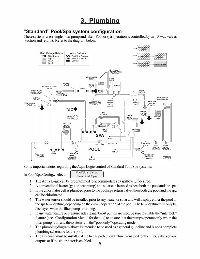
3. Plumbing“Standard” Pool/Spa system configurationThese systems use a single filter pump and filter. Pool or spa operation is controlled by two 3-way valves(suction and return). Refer to the diagram below.
Some important notes regarding the Aqua Logic control of Standard Pool/Spa systems:
In Pool/Spa Config., select: Pool/Spa SetupPool and Spa
1. The Aqua Logic can be programmed to accommodate spa spillover, if desired.2. A conventional heater (gas or heat pump) and solar can be used to heat both the pool and the spa.3. If the chlorinator cell is plumbed prior to the pool/spa return valve, then both the pool and the spa
can be chlorinated4. The water sensor should be installed prior to any heater or solar and will display either the pool or
the spa temperature, depending on the current operation of the pool. The temperature will only bedisplayed when the filter pump is running.
5. If any water feature or pressure side cleaner boost pumps are used, be sure to enable the “interlock”feature (see “Configuration Menu” for details) to ensure that the pumps operate only when thefilter pump is on and the system is in the “pool only” operating mode.
6. The plumbing diagram above is intended to be used as a general guideline and is not a completeplumbing schematic for the pool.
7. The air sensor must be installed if the freeze protection feature is enabled for the filter, valves or auxoutputs or if the chlorinator is enabled. 823
Solar ExtendIf “Enabled”, the filter extend logic keeps the filter pump running beyond the normal turn-offtime if solar heat is still available. When solar heat is no longer available, both the solarvalve/pump and filter pump will turn off simultaneously. Solar extend will NOT cause thefilter pump to turn on, it will only delay the turn off time when solar is operating.
Solar PriorityIf both “Solar Control” and “Heater Control” are enabled, the Solar Priority feature will keepthe conventional heater off whenever solar heat is available. This provides the most costeffective way of heating the pool. When solar heat is not available, the conventional heaterwill operate normally.
Lights InterlockDisabled
Lights FreezeDisabled
+
+
>
>
>
>
Toggle between Enabled and Disabled (default) Lights Interlock
Toggle between Enabled and Disabled (default) Lights Freeze Protectio
Move to next menu item
Move to previous/next configuration menu
Lights Config.+ to view/change
Lights FunctionManual On/Off
Lights RelayStandard
+
+
+
>
>
>>
>
>
Push to access Lights options
Rotates between options, and Super Chlorinate
Manual On/Off (default), Countdown Timer, TimeclockSolar, Low speed of a 2-speed pump
Toggle between Standard (default) and Dimmer
Move to previous/next configuration menu item
Move to next menu item
Move to next menu item or previous/next configuration menufor all functions except solar andlow speed of 2-speed filter pump and dimmer
for all functions except low speed of 2-speed filter pump
for manual on/off, countdowntimer and timeclock functions
Lights FunctionAlthough designated as the “Lights” output, the function of the lights relay is similar to theaux1 and aux2 relays. If pool lights are wired to the lights relay, some options including Solarfunction, Low Speed of a 2-Speed Filter Pump, Lights Interlock and Lights Freeze Protectionwill not be necessary and should be disabled. If no pool lights are used, the lights relay canbe used to control other pool devices that may require these options. The function of eachoption is shown below.
Manual On/Off—the lights relay will alternate between turning on and off when the LIGHTSbutton is pressed. There is no automatic control logic.
Countdown Timer—the lights relay will turn on when the LIGHTS button is pressed. Thelights relay will turn off automatically after a programmed time (see Timers Menu in OperationManual). The LIGHTS button can also be used to turn the output off.
Timeclock – the lights relay will turn-on and turn-off at the times set for the lights timeclockin the Timers Menu (see Timers Menu in Operation Manual). The LIGHTS button can alsobe used to turn the output on and off.
Solar – the lights relay can operate a solar booster pump which will turn on when the filterpump is running and solar heat is available and the water is less than the desired temperaturesetting. It is important to note that “Solar Control” must be enabled in the “Solar Config.”menu for proper operation to occur.
Low Speed of a 2-speed Filter Pump – the Aqua Logic will turn on the lights relay wheneverthe low speed operation of the filter pump is required. It is very important that the “2-speed”filter pump option be selected under the “Filter Config.” Menu for proper operation.
FILTER
SOLAR BOOSTPUMP
SOLARVALVE
HEATER
HEATERBYPASSVALVE
(manual)
CELLFLOW
SWITCH
CHECKVALVE
POOL SWEEPBOOST PUMP
WATERFEATURE
PUMP
POOL/SPARETURN VALVE
WATERFEATURE
VALVE
SPASPA JET
PUMP
SPABLOWER
POOL/SPA SUCTIONVALVE
CHECK VALVE
POOL VACUUMVALVE
MANUALVALVE
MANUALVALVE
MANUALVALVE
ENERGYFILTER
TWO-WAYVALVE
SKIM
POP-UP
SPILLOVER
POP-UP
OVERFLOW
POP-UP
RETURNJET
IN-FLOORCLEANER
VALVEWATER
FEATURE
PUMPWATER
FEATUREPOP-UP
MAINDRAIN ENERGY
SAVERPRESSURECLEANER
NON-BOOSTPRESSURECLEANER
PRESSURECLEANER
SUCTIONCLEANER
SOLARTEMPERATURE
SENSOR
POOL
FILTERPUMP
High Voltage Relays Valve OutputsFilter PumpLightsAux 1Aux 2
Pool/Spa SuctionPool/Spa ReturnValve 3
TRANSFORMER
HIGH VOLTAGELIGHTS
LOW VOLTAGELIGHTS
FIBER OPTICLIGHT SOURCE COLOR WHEEL
ISOLATEDWATER
FEATURE
PUMP
POOL/SPATEMPERATURE
SENSOR
CHECKVALVE
(prevents drainingof raised spas)
CHECKVALVE(prevents draining
of raised spas)

Turbo Cell (supplied with AQL-CL chlorination kit)The Turbo Cell (used for chlorine generation) should be plumbed AFTER the filter and heater. If installedon a pool/spa combination system, the cell should be plumbed BEFORE the pool/spa return valve in orderto allow proper chlorination of both the pool and the spa. Refer to plumbing diagram below:
The cell may be mounted vertically or horizontally, and water can move in either direction through the cell.Install using the 2" unions provided. Tighten unions BY HAND for a watertight seal. For systems with1½“ plumbing use adaptors (provided by installer).
Flow Switch (supplied with AQL-CL chlorination kit)The flow switch must be plumbed in the same section of plumbing as the Turbo Cell. The flow switch is asafety device that ensures that water is flowing through the cell before the Aqua Logic starts to generatechlorine. Failure to properly install the flow switch can result in explosive gases accumulating in the poolplumbing system.
! IMPORTANT: There must be at least a 12" (30cm) straight pipe run before (upstream)the flow switch. If the switch is plumbed after the cell, the cell can by counted as the 12" (30cm)of straight pipe.
! IMPORTANT: To ensure proper operation, verify that the arrow on the flow switch pointsin the direction of water flow.
9
12”min
Flow switch before cell Flow switch after cell
22
Heater1If the heater is “Enabled”, the heater relay will turn on when the water temperature is lessthan the desired temperature setting and the filter pump is running. The desired temperatureis in the “Settings Menu”. If applicable, the homeowner will be prompted to enter separate“pool” and “spa” settings. Depending on the position of the pool/spa suction valve, theproper temperature setting will be used.
Heater CooldownThis feature ensures that the heater cools down before water circulation is stopped. Whenenabled, the Aqua Logic will continue to run the filter pump for 5 minutes after the heaterturns off. During this period the filter pump LED will flash and also a “Heater Cooldown,X:XX remaining” message will scroll on the display.
When the filter pump is running and the heater is on: Pressing the “Filter” button once willcause the heater to turn off, but the filter pump will continue to run for heater cooldown (filterLED flashing and message on display). Pushing the filter button a second time will overridethe heater cooldown operation and turn the filter pump off.
Heater ExtendIf “Enabled”, the filter extend logic keeps the filter pump running beyond the normal turn-offtime until the pool (or spa) is heated up to the desired temperature setting (see SettingsMenu). Heater extend will NOT cause the filter pump to turn on, it will only delay the turnoff time when the heater is operating.
Allow Low SpeedThis menu only appears if the pool filter is configured for 2-speed operation. During defaultoperation, high speed mode is used whenever the heater is on. If Allow Low Speed is“Enabled”, low speed will be allowed whenever the heater is on.
+>>
+>>
+
+
>
>
>
>
+>>
Solar Config.+ to view/change
Solar Disabled
Solar Extend Disabled
Solar Priority Disabled
Push to access solar options
Toggle between Enabled and Disabled (default) Solar
Toggle between Enabled and Disabled (default) Solar Extend
Toggle between Enabled and Disabled (default) Solar Priority
Move to previous/next configuration menu
Move to next menu item or previous/next configuration menu
Move to next menu item
Move to previous/next configuration menu
if “Solar” is enabled
if “Solar” is enabled
SolarIf the solar control logic is “Enabled”, several additional steps must be taken to ensureproper operation of the solar system. If the solar is operated by a valve, then the Valve3output must be setup for solar logic (page 25). If the solar is operated by a pump, then oneof the AUX relays must be set up for solar logic (page 24). Also, the “solar” temperaturesensor must be installed. This sensor is typically mounted near the collector array and isused to sense whether sufficient solar heat is available.
If solar is “Enabled”, the valve or solar pump relay will turn on when the water temperature isless than the desired temperature setting AND the solar sensor is hotter than the water. Thedesired temperature is in the “Settings Menu”. If applicable, the homeowner will be promptedto enter separate pool and spa desired temperature settings. Depending on the position ofthe pool/spa suction valve, the proper temperature setting will be used.

4. Electrical Wiring
The Aqua Logic Control Center requires both high and low voltage connections. Low voltage connectionswill be made to actuators, sensors, remote keypad, etc. High voltage connections will be made to pumps,lights, etc., as well as providing direct input power to the Control Center. Always:
-Ensure that Power is disconnected prior to doing any wiring-Follow all local and NEC (CEC if applicable) codes-Use copper conductors only
Main Service (Power to the Circuit Breaker Subpanel)The Aqua Logic circuit breaker subpanel is rated for 100A service. Run properly rated conductors (L1,L2, N, and ground) from the primary house electrical panel to the main power connections on the AquaLogic circuit breaker base. The connection at the main house panel should be to a 240VAC circuitbreaker rated at 100A maximum.
Grounding and BondingConnect a ground wire from the primary electrical panel to the Aqua Logic ground bus bar. Also groundeach piece of high voltage (120 or 240VAC) equipment that is connected to the Aqua Logic control relaysor circuit breakers. The Aqua Logic should also be connected to the pool bonding system by an 8AWG(6AWG for Canada) wire. A lug for bonding (2 for Canada) is provided on the outside/bottom of theAqua Logic enclosure.
Circuit Breaker Installation and WiringCircuit breakers are to be supplied by the installer. Refer to the circuit breaker chart on the following pagefor a list of suitable circuit breakers that can be used. Follow the code and the circuit breaker manufacturer’srating requirements regarding the size and temperature rating for wiring. Note that some pool equipmentmay be required to be connected to ground fault circuit breakers—check local and NEC (CEC) codes.
1021
V1=Aux1, V2=Aux2This menu appears only if the Pool/Spa Setup is “Pool Only” or “Spa Only”. When enabled,Valve 1 (return) will follow the Aux1 output and Valve 2 (suction) will follow the Aux2 output.When disabled (default), the return and suction pool/spa valves function normally.
Filter Off Valve ChangeThis menu appears only if Pool/Spa setup is set to “Pool and Spa - Std”. When enabled(default), the filter pump will shut off for 35 seconds whenever the Pool/Spa valves areturning. The pump will NOT shut off when a heater is in Heater Cooldown mode.
+>>
+>>
+
+
>
>
>
>
+>>
Filter Pump Config.+ to view/change
Filter Pump 1 Speed
Freeze Protect Enabled
Freeze Temp38ºF
Push to access pump options
Toggle between 1-speed (default) and 2-speed options
Toggle between Enabled (default) and Disabled Freeze Protection
Adjust the desired freeze protection temperature (33ºF - 42ºF)
Move to next menu item
Move to previous/next configuration menu
Move to next menu item or previous/next configuration menu
Move to previous/next configuration menu
Filter PumpSelect single speed or 2-speed pump. If a 2-speed pump is configured, one of the AUXrelays must also be configured to control the low speed motor winding on the pump (seepage 12 for wiring and page 24 for AUX configuration). See the Operation Manual forspecific information regarding the control logic for 2-speed pump operation.
Freeze ProtectionFreeze protection is used to protect the pool and plumbed equipment against freeze damage.If freeze protection is enabled and the AIR temperature sensor falls below the freeze threshold(see below), the Aqua Logic will turn on the filter pump to circulate the water. If “Pool andSpa” is selected in the Pool/Spa sub-menu (see page 20), the valves will also alternatebetween the pool and spa every 30 minutes and the filter pump will turn off while the valvesare turning. The chlorinator will not operate if freeze protection is the only reason the pumpis running.
Freeze Protection TemperatureSelect the temperature to be used for freeze protection. Temperature is adjustable from 33ºF- 42ºF (1ºC - 6ºC). 38ºF (3ºC) is default. This threshold will be used for all outputs that havefreeze protection enabled.
+>>
+>>
+
+
+
>
>
>
>
>
>
+>>
Heater1 Config.+ to view/change
Heater1 Disabled
Heater1 Cooldown Disabled
Heater1 Extend Disabled
Allow Low Speed Disabled
Push to access heater options
Toggle between Enabled and Disabled (default) Heater 1
Toggle between Enabled and Disabled (default) Heater 1 Cooldown
Toggle between Enabled and Disabled (default) Heater 1 Extend
Toggle between Enabled and Disabled (default)
Move to previous/next configuration menu
Move to next menu item or previous/next configuration menu
Move to next menu item
Move to previous/next configuration menu
Move to next menu item or previous/next configuration menu
if “Heater1” is enabled
if “Heater1” is enabled
if “Heater1” is enabled and2-speed filter pump is enabled
High VoltageRelays
“Local” Display
Control PowerInput
Subpanel
Valve Connectors
Heater Output
Sensor Inputs
Remote Keypad
Flow Switch
Cell
xx

General Purpose OutletIf desired, a duplex receptacle with weatherproof cover (supplied by installer) may be installed in theknockouts on the lower right side of the Aqua Logic enclosure. Per code, the receptacle should be aGFCI type. Alternatively, connect a standard receptacle to a GFCB.
Aqua Logic Control PowerThe Aqua Logic requires 120VAC, 2A power to operate the control logic circuits and the chlorinator.This power should be connected to one of the circuit breakers.
! WARNING: 120VAC only (permanent damage if connected to 240V)
11
Pool/Spa Config.+ to view/change
Pool/Spa SetupPool and Spa
Spa Spillover Enabled
Filter OperationSpa Spillover
Push to access Pool/Spa options
Rotates between Pool and Spa, Spa Only, and Pool Only (default) optio
Toggle between Enabled and Disabled Spa Spillover(default)
Toggle between Pool Only and Spa Spillover options(default)
Move to previous/next configuration menu item
Move to next menu item
Move to next menu item or previous/next configuration menu
Move to next menu item or previous/next configuration menu
if “Pool and Spa” is selected and if “Spa Spillover” is enabled
Spa - CountDn 00:30
Adjust time setting (Manual on/off, 0:05, 0:10, 0:15..., (default is 4:00))Move to next menu item
if “Pool and Spa” is selected
if “Pool and Spa” is selected
V1=Aux1, V2=Aux2Disabled
Filter Off ValveChange: Enabled
Toggle between Enabled and Disabled (default)
Toggle between Enabled and Disabled (default)
if “Pool Only” or “Spa Only” is selected
if “Pool and Spa-Std” is selected
Move to previous/next configuration menu
Move to previous/next configuration menu
+>>
+>>
+
+
+
>
>
>
>
>
>
+
+
>
>
>
>
+>>
Pool/Spa SetupIf “Pool Only” or “Spa Only” are selected, then the pool/spa valves are not needed andpushing the POOL/SPA button on the display/keypad will have no effect. If “Pool and Spa”is selected, then the pool/spa suction and return valve actuators should be connected to theAqua Logic. Pressing the POOL/SPA button on the display/keypad will allow the homeownerto alternate between pool and spa operation. For more information on “Pool and Spa”, referto the Plumbing section on pages 8.
Spa CountDnThis menu will appear only if Pool/Spa Setup is set to “Pool and Spa”. This setting is thetime, after you manually switch the Pool/Spa valves to “Spa Only”, until the Aqua Logicautomatically returns the valves to their previous positions. It is programmed in incrementsof 5 minutes, from “Manual On/Off” (0 minutes) to “21:00” (21 hours). The filter is forced onduring this time period.
Spa SpilloverWhen spa spillover is “Enabled” and “Pool and Spa”, the homeowner will be able to rotatethrough “Pool Only” (both suction and return valves switched to pool), “Spa Only” (bothsuction and return valves switched to spa) and “Spillover” (suction valve switched to pooland return valve switched to spa) by successive presses of the “Pool/Spa) button.
Filter OperationIf “Spa Spillover” is selected, the Aqua Logic will automatically switch the pool/spa suctionand return valves to “spillover” at the start of the programmed pool filtering time period orwhen the super-chlorinate function is turned on. The valves will remain in this position forthe remainder of the super-chlorinate period. This option is usually preferable because boththe pool and spa water will be filtered and sanitized.
If “Pool Only” is selected, then the Aqua Logic will switch the pool/spa valves to the “poolonly” position at the start of the programmed pool filtering time period or when the super-chlorinate function is turned on. This may be desirable on some systems with in-floorcleaners because it allows the cleaner to operate all the time the pool is being filtered and/orthe super chlorinate is running.
20
Cutler-HammerMurraySiemensSquare DThomas & Betts
Manufacturer Single Double QuadTwin GFCB Filler Plates
BRMP-TQP
HOMTB
BRMP-TQP
HOMTB
BRDMH-T
QTHOMTTBBD
BRDMH-TQT
HOMTTBBQ
GFCBMP-GT
QPFHOMGFB
BRFPLX100FP
QF3HOMFP
FP-1C-TB
SUITABLE LISTED BREAKERS
FactoryPrewired
FieldWired
120, 2VA

High Voltage (120/240V) Pool EquipmentAll Aqua Logic relays are double pole (they make/break both “legs” of 240V circuits) and are rated at3HP/30A at 240V (1½HP/30A at 120V). Refer to the diagram below for typical relay wiring.
! WARNING: Do not use the Aqua Logic to control an automatic pool cover. Swim-mers may become entrapped underneath the cover.
Two speed filter pump: Requires 2 relays (FILTER plus one of the AUX relays) for proper operation ofboth speeds. ! IMPORTANT: Be sure to follow the wiring diagram below AND to configurethe control logic according to the instructions on page 21.
Lights: A ground fault circuit breaker must be used to supply power for high voltage pool/spa lighting.Low voltage lights will require an external transformer. For lighting systems that have both a light sourceand color wheel, connect the light source to the “Lights” relay and then connect the color wheel to one ofthe AUX outputs.
12
240 VACLoad
120 VACLoad
Wiring relays for 240 VACPool Equipment
Wiring relays for 120 VACPool Equipment
120 VACLoad
Wiring GFCB for 120 VPool Equipment
5. Configuration SetupAfter plumbing and wiring are complete, the Aqua Logic MUST BE CONFIGURED before attempting tooperate. Configuration information is entered at the keypad and “tells” the Aqua Logic what equipment isconnected and how each should be controlled.
Accessing the Configuration MenuConfiguring the Aqua Logic requires that you navigate through the Configuration Menu and input variousinformation. For more detailed information about using the Aqua Logic menu system, refer to the Opera-tion Manual.
To access the Configuration Menu
ConfigurationMenu-Unlocked
ConfigurationMenu-Locked
Press repeatedly until “Configuration Menu” is displayed
Move to configuration menu
Press BOTH buttons SIMULTANEOUSLY for 5 seconds to unlockMenu
>
>
>
>
NOTE: The configuration menu automatically “locks” after 2 minutes of no buttons beingpressed to prevent unauthorized people from changing the control logic inadvertently andpossibly damaging the pool equipment or causing a “call back” to fix the configuration.
Configuration Menu ItemsEach item needs to be programmed and may contain additional sub-menu items. Refer to the followingpages for information on programming.
ChlorinatorDisabled
Chlor. Config.+ to view/change
Move to next menu item
Move to next configuration menu Push to access Chlorinator option
Toggle between Chlorinator Enabled and Disabled (default)
+
+>
>
>
>
+
+>
>
>
>
+>>
DisplaySalt
Toggle between Display Salt (default) and Minerals Move to previous/next configuration menu
ChlorinatorIf the chlorinator is enabled (requires the use of the AQL-CL chlorination kit), then the celland flow switch must also be installed and the Aqua Logic will automatically chlorinate boththe pool and spa according to the desired output setting (see Settings Menu in the Operationmanual). If disabled (default), then neither the cell nor flow switch need to be installed andall displays relating to the chlorinator will be suppressed.
When the chlorinator is enabled, the Aqua Logic will automatically detect and control anyAqua Rite(s) that is installed in the system (see page 18).
DisplayAllows for the display of salt (default) or mineral values.
Cell TypeT-CELL-15
Toggle between T-CELL-5 and T-CELL-15 (default)Move to next menu item
+>>
Cell Type SelectionThe Cell Type Menu appears after “Display Salt/Minerals” in the Chlorinator ConfigurationMenu. The options are T-CELL-5 or T-CELL-15 (default). Make the proper selection basedon the electrolytic cell that is used in your system. For pools up to 20,000 gallons, the T-CELL-5 is typically used. The T-CELL-15 is for pools up to 40,000 gallons.
19
N
2-SpeedFilter Pump
GL1L2
Lo SpeedHi SpeedCommonGround

Low Voltage WiringValve ActuatorsThe Aqua Logic can control up to three automatic valve actuators. Two of the valve outputs are dedicatedto the pool/spa suction (Valve2) and return (Valve1) valves. Valve3 is for general purpose use (solar,water feature, in-floor cleaner, etc.).
For installations with solar heating, Goldline offers the AQ-SOL-KIT-xx solar kit that contains a valve,actuator, and extra temperature sensor. The “xx” indicates the valve type from the 3 choices below:
-1P 1.5” Positive Seal-2P 2” Positive Seal
The Aqua Logic is compatible with standard valve actuators manufactured by Hayward, Pentair/Compool,and Jandy. See diagram on page 10 for the location of valve connectors.
Heater ControlThe Aqua Logic provides a set of low voltage dry contacts that can be connected to most gas heaters orheat pumps with 24V control circuits. Refer to the diagram below for a generic connection. The manualssupplied with most heaters also include specific wiring instructions for connecting the heater to an externalcontrol (usually identified as “2-wire” remote control). For millivolt or line voltage heaters, contact Gold-line Tech support, 888-921-7665. Refer to the diagrams and the information on the following pages formore details on the connection to several popular heaters.
Generic Heaters1. Wire heater to 120/240V power source per the instructions in the heater manual. The Aqua Logic
does NOT control the power going to the heater.2. Wire the Aqua Logic dry contact heater output per the diagram below. Many internal parts of the
heater can get very hot--see the heater manufacturer’s recommendations on the minimum temperaturerating for wires. If no guidance is given, use 105°C rated wire.
3. Set any ON/OFF switch on the heater to ON.4. Set the thermostat(s) on the heater to the maximum (hottest) setting.
13
Flow SwitchOnly applicable if the chlorinator function is enabled. The flow switch cable plugs into the Aqua LogicControl Center at the position shown in the diagram on page 10. Ensure that the connector catch “snaps”in order to provide a reliable connection.
Turbo CellOnly applicable if the chlorinator function is enabled. The Turbo Cell should be plugged in after theAqua Logic cover panel is put back in place. Refer to page 10 for the location of the connector.
Goldline Aqua Rite ChlorinatorThe Aqua Logic can control one or more Goldline Aqua Rite chlorinators when additional sanitizing capac-ity is required. A 4 wire connection is used to communicate to the Aqua Rite and can be wired up to 500'apart. Any outdoor rated 4 conductor cable can be used. Refer to the wiring diagrams below for properwiring connection to the Aqua Rite. NOTE: There must be only 1 "primary" unit. All other Aqua Rite unitsmust be configured as "secondary".
18
Ignition/ValveHeater
Kill SwitchThermostat
xx
AirSolar
Pool/Spa
Heater
4 43 3
2 21 1
GRN GRN
BLK BLKYEL YEL
RED REDAqua Logic Aqua Rite
green
yellow
black
red
Aqua Logic Aqua Rite(Primary)
Aqua Rite(Secondary)
AdditionalAqua Rite(s)(if required)
Jumper RemovedFor Secondary(s)Jumper Installed
For Primary(Factory Default)
1234 GREEN
YELLOWBLACKRED
NOTE: Primary/Secondary jumper is located underneath small circuit board.

Laars Heaters1. Turn power off to heater.2. Remove factory jumper from terminal block.3. Wire Aqua Logic to the heater as shown.4. Ensure toggle switch is in the ON position.5. Set heater thermostats to maximum position.
Hayward HeatersRefer to the instructions in the heater manual for “2-wire Remote Thermostat” operation under “RemoteControl Connections” and the diagram below:
1. Turn off power to heater.2. Wire Aqua Logic to terminals 1 & 2 (see diagram).3. Leave jumper attached to terminals 4 & 5.4. Move “BYPASS” dipswitch on heater circuit board to “ON” position (up).5. Turn heater power back on.6. Switch heater to either “Pool” or “Spa” (it doesn’t make any difference which is selected, the Aqua
Logic will take control).7. Heater display should be “bO” (for “bypass On).8. Heater will fire whenever Aqua Logic requests (when Aqua Logic “Heater” LED is illuminated).
14
Remote Display/KeypadThe Aqua Logic main unit can connect to a maximum of 3 remote wired display/keypads (ordered sepa-rately).
Use four conductor cable (typically phone cable) to connect the wired remote display/keypad with theAqua Logic Control Center as shown below. The maximum wiring distance is 500ft. (160m). Note thatthe terminals on both the Aqua Logic main unit and the wired remote display/keypad are numbered:Connect 1 to 1, 2 to 2, etc. Refer to diagram below.
If multiple remote display/keypads are installed: Never connect more than 2 wires to any terminalblock. Two remotes can be wired back to the Aqua Logic main unit or the second display/keypad (andthird, if applicable) can be “daisy chained” with one display/keypad wired to the next. The maximum wirerun from the Aqua Logic main unit to the furthest remote display/keypad is 500 ft (160m).
Base ReceiverPlug in the pigtail connector from the wireless base receiver into the “wireless” connector on the main PCBin the Aqua Logic control unit.
17
xx
AirSolar
Pool/Spa
Heater
to limit switches
remove jumper
Fusible Link
white
white
xx
AirSolar
Pool/Spa
Heater
Do not remove jumperTerminal block located atelectrical junction box
Dipswitch located on heatercircuit board
PK
W
R
BK
R
ONºC
OFFºF
xx
AirSolar
Pool/Spa
Heater
Remote Display unit
AlternativeConcealed Wiring
1234
500 ft max
3.75 ”
4.50 ”
1234
xx
Base Receiver(AQL-BASE-RF
or2 )AQL -BASE-RF
Tighten nut
Main PCB
Connector for Base Receiver
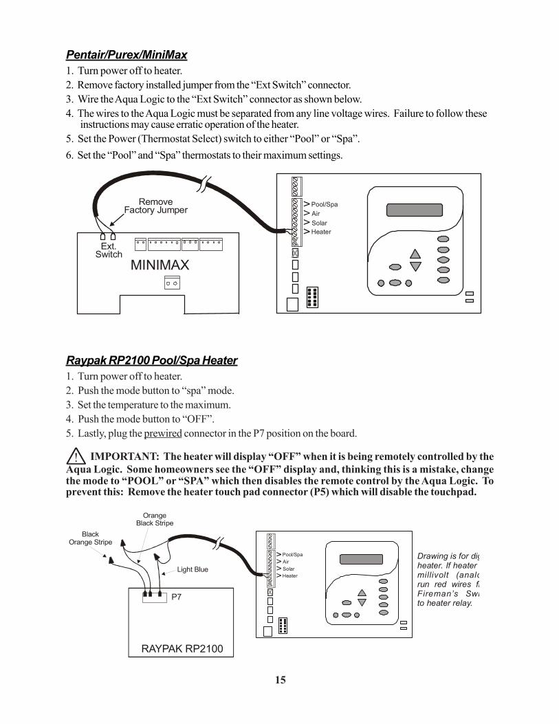
Pentair/Purex/MiniMax1. Turn power off to heater.2. Remove factory installed jumper from the “Ext Switch” connector.3. Wire the Aqua Logic to the “Ext Switch” connector as shown below.4. The wires to the Aqua Logic must be separated from any line voltage wires. Failure to follow these
instructions may cause erratic operation of the heater.5. Set the Power (Thermostat Select) switch to either “Pool” or “Spa”.6. Set the “Pool” and “Spa” thermostats to their maximum settings.
Raypak RP2100 Pool/Spa Heater1. Turn power off to heater.2. Push the mode button to “spa” mode.3. Set the temperature to the maximum.4. Push the mode button to “OFF”.5. Lastly, plug the prewired connector in the P7 position on the board.
! IMPORTANT: The heater will display “OFF” when it is being remotely controlled by theAqua Logic. Some homeowners see the “OFF” display and, thinking this is a mistake, changethe mode to “POOL” or “SPA” which then disables the remote control by the Aqua Logic. Toprevent this: Remove the heater touch pad connector (P5) which will disable the touchpad.
15
STA-RITE Heater1. Turn power off to heater.2. Remove upper jacket and open the control box.3. Remove the jumper for the “fireman’s switch.4. Wire to the Aqua Logic using wire rated for 105°C minimum.
Temperature SensorsThe Aqua Logic utilizes 10K ohm thermistor type sensors. Three sensors (water temperature, air tem-perature and solar temperature) are included. If the Aqua Logic is being used to control a solar heatingsystem, the solar sensor is required. The sensors are provided with a 15 ft. cable. If a longer cable isrequired, contact the Goldline service dept. (888-921-7665) for information on suitable cable types andsplices. See page 6 and 16 for installation information.
16
xx
AirSolar
Pool/Spa
Heater
MINIMAXExt.
Switch
Remove Factory Jumper
xx
AirSolar
Pool/Spa
Heater
STA-RITE
TerminalBoard
Operating‘Control
Fireman’sSwitch
xx
AirSolar
Pool/Spa
Heater
P7
Light Blue
BlackOrange Stripe
OrangeStripeBlack
RAYPAK RP2100
Drawing is for digheater. If heater millivolt (analorun red wires frFireman’s Swito heater relay.
xx
AirSolar
Pool/Spa
Heater
AIRSENSOR
SOLAR/SPASENSOR
POOL/SPASENSOR

Laars Heaters1. Turn power off to heater.2. Remove factory jumper from terminal block.3. Wire Aqua Logic to the heater as shown.4. Ensure toggle switch is in the ON position.5. Set heater thermostats to maximum position.
Hayward HeatersRefer to the instructions in the heater manual for “2-wire Remote Thermostat” operation under “RemoteControl Connections” and the diagram below:
1. Turn off power to heater.2. Wire Aqua Logic to terminals 1 & 2 (see diagram).3. Leave jumper attached to terminals 4 & 5.4. Move “BYPASS” dipswitch on heater circuit board to “ON” position (up).5. Turn heater power back on.6. Switch heater to either “Pool” or “Spa” (it doesn’t make any difference which is selected, the Aqua
Logic will take control).7. Heater display should be “bO” (for “bypass On).8. Heater will fire whenever Aqua Logic requests (when Aqua Logic “Heater” LED is illuminated).
14
Remote Display/KeypadThe Aqua Logic main unit can connect to a maximum of 3 remote wired display/keypads (ordered sepa-rately).
Use four conductor cable (typically phone cable) to connect the wired remote display/keypad with theAqua Logic Control Center as shown below. The maximum wiring distance is 500ft. (160m). Note thatthe terminals on both the Aqua Logic main unit and the wired remote display/keypad are numbered:Connect 1 to 1, 2 to 2, etc. Refer to diagram below.
If multiple remote display/keypads are installed: Never connect more than 2 wires to any terminalblock. Two remotes can be wired back to the Aqua Logic main unit or the second display/keypad (andthird, if applicable) can be “daisy chained” with one display/keypad wired to the next. The maximum wirerun from the Aqua Logic main unit to the furthest remote display/keypad is 500 ft (160m).
Base ReceiverPlug in the pigtail connector from the wireless base receiver into the “wireless” connector on the main PCBin the Aqua Logic control unit.
17
xx
AirSolar
Pool/Spa
Heater
to limit switches
remove jumper
Fusible Link
white
white
xx
AirSolar
Pool/Spa
Heater
Do not remove jumperTerminal block located atelectrical junction box
Dipswitch located on heatercircuit board
PK
W
R
BK
R
ONºC
OFFºF
xx
AirSolar
Pool/Spa
Heater
Remote Display unit
AlternativeConcealed Wiring
1234
500 ft max
3.75 ”
4.50 ”
1234
xx
Base Receiver(AQL-BASE-RF
or2 )AQL -BASE-RF
Tighten nut
Main PCB
Connector for Base Receiver

Low Voltage WiringValve ActuatorsThe Aqua Logic can control up to three automatic valve actuators. Two of the valve outputs are dedicatedto the pool/spa suction (Valve2) and return (Valve1) valves. Valve3 is for general purpose use (solar,water feature, in-floor cleaner, etc.).
For installations with solar heating, Goldline offers the AQ-SOL-KIT-xx solar kit that contains a valve,actuator, and extra temperature sensor. The “xx” indicates the valve type from the 3 choices below:
-1P 1.5” Positive Seal-2P 2” Positive Seal
The Aqua Logic is compatible with standard valve actuators manufactured by Hayward, Pentair/Compool,and Jandy. See diagram on page 10 for the location of valve connectors.
Heater ControlThe Aqua Logic provides a set of low voltage dry contacts that can be connected to most gas heaters orheat pumps with 24V control circuits. Refer to the diagram below for a generic connection. The manualssupplied with most heaters also include specific wiring instructions for connecting the heater to an externalcontrol (usually identified as “2-wire” remote control). For millivolt or line voltage heaters, contact Gold-line Tech support, 888-921-7665. Refer to the diagrams and the information on the following pages formore details on the connection to several popular heaters.
Generic Heaters1. Wire heater to 120/240V power source per the instructions in the heater manual. The Aqua Logic
does NOT control the power going to the heater.2. Wire the Aqua Logic dry contact heater output per the diagram below. Many internal parts of the
heater can get very hot--see the heater manufacturer’s recommendations on the minimum temperaturerating for wires. If no guidance is given, use 105°C rated wire.
3. Set any ON/OFF switch on the heater to ON.4. Set the thermostat(s) on the heater to the maximum (hottest) setting.
13
Flow SwitchOnly applicable if the chlorinator function is enabled. The flow switch cable plugs into the Aqua LogicControl Center at the position shown in the diagram on page 10. Ensure that the connector catch “snaps”in order to provide a reliable connection.
Turbo CellOnly applicable if the chlorinator function is enabled. The Turbo Cell should be plugged in after theAqua Logic cover panel is put back in place. Refer to page 10 for the location of the connector.
Goldline Aqua Rite ChlorinatorThe Aqua Logic can control one or more Goldline Aqua Rite chlorinators when additional sanitizing capac-ity is required. A 4 wire connection is used to communicate to the Aqua Rite and can be wired up to 500'apart. Any outdoor rated 4 conductor cable can be used. Refer to the wiring diagrams below for properwiring connection to the Aqua Rite. NOTE: There must be only 1 "primary" unit. All other Aqua Rite unitsmust be configured as "secondary".
18
Ignition/ValveHeater
Kill SwitchThermostat
xx
AirSolar
Pool/Spa
Heater
4 43 3
2 21 1
GRN GRN
BLK BLKYEL YEL
RED REDAqua Logic Aqua Rite
green
yellow
black
red
Aqua Logic Aqua Rite(Primary)
Aqua Rite(Secondary)
AdditionalAqua Rite(s)(if required)
Jumper RemovedFor Secondary(s)Jumper Installed
For Primary(Factory Default)
1234 GREEN
YELLOWBLACKRED
NOTE: Primary/Secondary jumper is located underneath small circuit board.

High Voltage (120/240V) Pool EquipmentAll Aqua Logic relays are double pole (they make/break both “legs” of 240V circuits) and are rated at3HP/30A at 240V (1½HP/30A at 120V). Refer to the diagram below for typical relay wiring.
! WARNING: Do not use the Aqua Logic to control an automatic pool cover. Swim-mers may become entrapped underneath the cover.
Two speed filter pump: Requires 2 relays (FILTER plus one of the AUX relays) for proper operation ofboth speeds. ! IMPORTANT: Be sure to follow the wiring diagram below AND to configurethe control logic according to the instructions on page 21.
Lights: A ground fault circuit breaker must be used to supply power for high voltage pool/spa lighting.Low voltage lights will require an external transformer. For lighting systems that have both a light sourceand color wheel, connect the light source to the “Lights” relay and then connect the color wheel to one ofthe AUX outputs.
12
240 VACLoad
120 VACLoad
Wiring relays for 240 VACPool Equipment
Wiring relays for 120 VACPool Equipment
120 VACLoad
Wiring GFCB for 120 VPool Equipment
5. Configuration SetupAfter plumbing and wiring are complete, the Aqua Logic MUST BE CONFIGURED before attempting tooperate. Configuration information is entered at the keypad and “tells” the Aqua Logic what equipment isconnected and how each should be controlled.
Accessing the Configuration MenuConfiguring the Aqua Logic requires that you navigate through the Configuration Menu and input variousinformation. For more detailed information about using the Aqua Logic menu system, refer to the Opera-tion Manual.
To access the Configuration Menu
ConfigurationMenu-Unlocked
ConfigurationMenu-Locked
Press repeatedly until “Configuration Menu” is displayed
Move to configuration menu
Press BOTH buttons SIMULTANEOUSLY for 5 seconds to unlockMenu
>
>
>
>
NOTE: The configuration menu automatically “locks” after 2 minutes of no buttons beingpressed to prevent unauthorized people from changing the control logic inadvertently andpossibly damaging the pool equipment or causing a “call back” to fix the configuration.
Configuration Menu ItemsEach item needs to be programmed and may contain additional sub-menu items. Refer to the followingpages for information on programming.
ChlorinatorDisabled
Chlor. Config.+ to view/change
Move to next menu item
Move to next configuration menu Push to access Chlorinator option
Toggle between Chlorinator Enabled and Disabled (default)
+
+>
>
>
>
+
+>
>
>
>
+>>
DisplaySalt
Toggle between Display Salt (default) and Minerals Move to previous/next configuration menu
ChlorinatorIf the chlorinator is enabled (requires the use of the AQL-CL chlorination kit), then the celland flow switch must also be installed and the Aqua Logic will automatically chlorinate boththe pool and spa according to the desired output setting (see Settings Menu in the Operationmanual). If disabled (default), then neither the cell nor flow switch need to be installed andall displays relating to the chlorinator will be suppressed.
When the chlorinator is enabled, the Aqua Logic will automatically detect and control anyAqua Rite(s) that is installed in the system (see page 18).
DisplayAllows for the display of salt (default) or mineral values.
Cell TypeT-CELL-15
Toggle between T-CELL-5 and T-CELL-15 (default)Move to next menu item
+>>
Cell Type SelectionThe Cell Type Menu appears after “Display Salt/Minerals” in the Chlorinator ConfigurationMenu. The options are T-CELL-5 or T-CELL-15 (default). Make the proper selection basedon the electrolytic cell that is used in your system. For pools up to 20,000 gallons, the T-CELL-5 is typically used. The T-CELL-15 is for pools up to 40,000 gallons.
19
N
2-SpeedFilter Pump
GL1L2
Lo SpeedHi SpeedCommonGround

General Purpose OutletIf desired, a duplex receptacle with weatherproof cover (supplied by installer) may be installed in theknockouts on the lower right side of the Aqua Logic enclosure. Per code, the receptacle should be aGFCI type. Alternatively, connect a standard receptacle to a GFCB.
Aqua Logic Control PowerThe Aqua Logic requires 120VAC, 2A power to operate the control logic circuits and the chlorinator.This power should be connected to one of the circuit breakers.
! WARNING: 120VAC only (permanent damage if connected to 240V)
11
Pool/Spa Config.+ to view/change
Pool/Spa SetupPool and Spa
Spa Spillover Enabled
Filter OperationSpa Spillover
Push to access Pool/Spa options
Rotates between Pool and Spa, Spa Only, and Pool Only (default) optio
Toggle between Enabled and Disabled Spa Spillover(default)
Toggle between Pool Only and Spa Spillover options(default)
Move to previous/next configuration menu item
Move to next menu item
Move to next menu item or previous/next configuration menu
Move to next menu item or previous/next configuration menu
if “Pool and Spa” is selected and if “Spa Spillover” is enabled
Spa - CountDn 00:30
Adjust time setting (Manual on/off, 0:05, 0:10, 0:15..., (default is 4:00))Move to next menu item
if “Pool and Spa” is selected
if “Pool and Spa” is selected
V1=Aux1, V2=Aux2Disabled
Filter Off ValveChange: Enabled
Toggle between Enabled and Disabled (default)
Toggle between Enabled and Disabled (default)
if “Pool Only” or “Spa Only” is selected
if “Pool and Spa-Std” is selected
Move to previous/next configuration menu
Move to previous/next configuration menu
+>>
+>>
+
+
+
>
>
>
>
>
>
+
+
>
>
>
>
+>>
Pool/Spa SetupIf “Pool Only” or “Spa Only” are selected, then the pool/spa valves are not needed andpushing the POOL/SPA button on the display/keypad will have no effect. If “Pool and Spa”is selected, then the pool/spa suction and return valve actuators should be connected to theAqua Logic. Pressing the POOL/SPA button on the display/keypad will allow the homeownerto alternate between pool and spa operation. For more information on “Pool and Spa”, referto the Plumbing section on pages 8.
Spa CountDnThis menu will appear only if Pool/Spa Setup is set to “Pool and Spa”. This setting is thetime, after you manually switch the Pool/Spa valves to “Spa Only”, until the Aqua Logicautomatically returns the valves to their previous positions. It is programmed in incrementsof 5 minutes, from “Manual On/Off” (0 minutes) to “21:00” (21 hours). The filter is forced onduring this time period.
Spa SpilloverWhen spa spillover is “Enabled” and “Pool and Spa”, the homeowner will be able to rotatethrough “Pool Only” (both suction and return valves switched to pool), “Spa Only” (bothsuction and return valves switched to spa) and “Spillover” (suction valve switched to pooland return valve switched to spa) by successive presses of the “Pool/Spa) button.
Filter OperationIf “Spa Spillover” is selected, the Aqua Logic will automatically switch the pool/spa suctionand return valves to “spillover” at the start of the programmed pool filtering time period orwhen the super-chlorinate function is turned on. The valves will remain in this position forthe remainder of the super-chlorinate period. This option is usually preferable because boththe pool and spa water will be filtered and sanitized.
If “Pool Only” is selected, then the Aqua Logic will switch the pool/spa valves to the “poolonly” position at the start of the programmed pool filtering time period or when the super-chlorinate function is turned on. This may be desirable on some systems with in-floorcleaners because it allows the cleaner to operate all the time the pool is being filtered and/orthe super chlorinate is running.
20
Cutler-HammerMurraySiemensSquare DThomas & Betts
Manufacturer Single Double QuadTwin GFCB Filler Plates
BRMP-TQP
HOMTB
BRMP-TQP
HOMTB
BRDMH-T
QTHOMTTBBD
BRDMH-TQT
HOMTTBBQ
GFCBMP-GT
QPFHOMGFB
BRFPLX100FP
QF3HOMFP
FP-1C-TB
SUITABLE LISTED BREAKERS
FactoryPrewired
FieldWired
120, 2VA

4. Electrical Wiring
The Aqua Logic Control Center requires both high and low voltage connections. Low voltage connectionswill be made to actuators, sensors, remote keypad, etc. High voltage connections will be made to pumps,lights, etc., as well as providing direct input power to the Control Center. Always:
-Ensure that Power is disconnected prior to doing any wiring-Follow all local and NEC (CEC if applicable) codes-Use copper conductors only
Main Service (Power to the Circuit Breaker Subpanel)The Aqua Logic circuit breaker subpanel is rated for 100A service. Run properly rated conductors (L1,L2, N, and ground) from the primary house electrical panel to the main power connections on the AquaLogic circuit breaker base. The connection at the main house panel should be to a 240VAC circuitbreaker rated at 100A maximum.
Grounding and BondingConnect a ground wire from the primary electrical panel to the Aqua Logic ground bus bar. Also groundeach piece of high voltage (120 or 240VAC) equipment that is connected to the Aqua Logic control relaysor circuit breakers. The Aqua Logic should also be connected to the pool bonding system by an 8AWG(6AWG for Canada) wire. A lug for bonding (2 for Canada) is provided on the outside/bottom of theAqua Logic enclosure.
Circuit Breaker Installation and WiringCircuit breakers are to be supplied by the installer. Refer to the circuit breaker chart on the following pagefor a list of suitable circuit breakers that can be used. Follow the code and the circuit breaker manufacturer’srating requirements regarding the size and temperature rating for wiring. Note that some pool equipmentmay be required to be connected to ground fault circuit breakers—check local and NEC (CEC) codes.
1021
V1=Aux1, V2=Aux2This menu appears only if the Pool/Spa Setup is “Pool Only” or “Spa Only”. When enabled,Valve 1 (return) will follow the Aux1 output and Valve 2 (suction) will follow the Aux2 output.When disabled (default), the return and suction pool/spa valves function normally.
Filter Off Valve ChangeThis menu appears only if Pool/Spa setup is set to “Pool and Spa - Std”. When enabled(default), the filter pump will shut off for 35 seconds whenever the Pool/Spa valves areturning. The pump will NOT shut off when a heater is in Heater Cooldown mode.
+>>
+>>
+
+
>
>
>
>
+>>
Filter Pump Config.+ to view/change
Filter Pump 1 Speed
Freeze Protect Enabled
Freeze Temp38ºF
Push to access pump options
Toggle between 1-speed (default) and 2-speed options
Toggle between Enabled (default) and Disabled Freeze Protection
Adjust the desired freeze protection temperature (33ºF - 42ºF)
Move to next menu item
Move to previous/next configuration menu
Move to next menu item or previous/next configuration menu
Move to previous/next configuration menu
Filter PumpSelect single speed or 2-speed pump. If a 2-speed pump is configured, one of the AUXrelays must also be configured to control the low speed motor winding on the pump (seepage 12 for wiring and page 24 for AUX configuration). See the Operation Manual forspecific information regarding the control logic for 2-speed pump operation.
Freeze ProtectionFreeze protection is used to protect the pool and plumbed equipment against freeze damage.If freeze protection is enabled and the AIR temperature sensor falls below the freeze threshold(see below), the Aqua Logic will turn on the filter pump to circulate the water. If “Pool andSpa” is selected in the Pool/Spa sub-menu (see page 20), the valves will also alternatebetween the pool and spa every 30 minutes and the filter pump will turn off while the valvesare turning. The chlorinator will not operate if freeze protection is the only reason the pumpis running.
Freeze Protection TemperatureSelect the temperature to be used for freeze protection. Temperature is adjustable from 33ºF- 42ºF (1ºC - 6ºC). 38ºF (3ºC) is default. This threshold will be used for all outputs that havefreeze protection enabled.
+>>
+>>
+
+
+
>
>
>
>
>
>
+>>
Heater1 Config.+ to view/change
Heater1 Disabled
Heater1 Cooldown Disabled
Heater1 Extend Disabled
Allow Low Speed Disabled
Push to access heater options
Toggle between Enabled and Disabled (default) Heater 1
Toggle between Enabled and Disabled (default) Heater 1 Cooldown
Toggle between Enabled and Disabled (default) Heater 1 Extend
Toggle between Enabled and Disabled (default)
Move to previous/next configuration menu
Move to next menu item or previous/next configuration menu
Move to next menu item
Move to previous/next configuration menu
Move to next menu item or previous/next configuration menu
if “Heater1” is enabled
if “Heater1” is enabled
if “Heater1” is enabled and2-speed filter pump is enabled
High VoltageRelays
“Local” Display
Control PowerInput
Subpanel
Valve Connectors
Heater Output
Sensor Inputs
Remote Keypad
Flow Switch
Cell
xx

Turbo Cell (supplied with AQL-CL chlorination kit)The Turbo Cell (used for chlorine generation) should be plumbed AFTER the filter and heater. If installedon a pool/spa combination system, the cell should be plumbed BEFORE the pool/spa return valve in orderto allow proper chlorination of both the pool and the spa. Refer to plumbing diagram below:
The cell may be mounted vertically or horizontally, and water can move in either direction through the cell.Install using the 2" unions provided. Tighten unions BY HAND for a watertight seal. For systems with1½“ plumbing use adaptors (provided by installer).
Flow Switch (supplied with AQL-CL chlorination kit)The flow switch must be plumbed in the same section of plumbing as the Turbo Cell. The flow switch is asafety device that ensures that water is flowing through the cell before the Aqua Logic starts to generatechlorine. Failure to properly install the flow switch can result in explosive gases accumulating in the poolplumbing system.
! IMPORTANT: There must be at least a 12" (30cm) straight pipe run before (upstream)the flow switch. If the switch is plumbed after the cell, the cell can by counted as the 12" (30cm)of straight pipe.
! IMPORTANT: To ensure proper operation, verify that the arrow on the flow switch pointsin the direction of water flow.
9
12”min
Flow switch before cell Flow switch after cell
22
Heater1If the heater is “Enabled”, the heater relay will turn on when the water temperature is lessthan the desired temperature setting and the filter pump is running. The desired temperatureis in the “Settings Menu”. If applicable, the homeowner will be prompted to enter separate“pool” and “spa” settings. Depending on the position of the pool/spa suction valve, theproper temperature setting will be used.
Heater CooldownThis feature ensures that the heater cools down before water circulation is stopped. Whenenabled, the Aqua Logic will continue to run the filter pump for 5 minutes after the heaterturns off. During this period the filter pump LED will flash and also a “Heater Cooldown,X:XX remaining” message will scroll on the display.
When the filter pump is running and the heater is on: Pressing the “Filter” button once willcause the heater to turn off, but the filter pump will continue to run for heater cooldown (filterLED flashing and message on display). Pushing the filter button a second time will overridethe heater cooldown operation and turn the filter pump off.
Heater ExtendIf “Enabled”, the filter extend logic keeps the filter pump running beyond the normal turn-offtime until the pool (or spa) is heated up to the desired temperature setting (see SettingsMenu). Heater extend will NOT cause the filter pump to turn on, it will only delay the turnoff time when the heater is operating.
Allow Low SpeedThis menu only appears if the pool filter is configured for 2-speed operation. During defaultoperation, high speed mode is used whenever the heater is on. If Allow Low Speed is“Enabled”, low speed will be allowed whenever the heater is on.
+>>
+>>
+
+
>
>
>
>
+>>
Solar Config.+ to view/change
Solar Disabled
Solar Extend Disabled
Solar Priority Disabled
Push to access solar options
Toggle between Enabled and Disabled (default) Solar
Toggle between Enabled and Disabled (default) Solar Extend
Toggle between Enabled and Disabled (default) Solar Priority
Move to previous/next configuration menu
Move to next menu item or previous/next configuration menu
Move to next menu item
Move to previous/next configuration menu
if “Solar” is enabled
if “Solar” is enabled
SolarIf the solar control logic is “Enabled”, several additional steps must be taken to ensureproper operation of the solar system. If the solar is operated by a valve, then the Valve3output must be setup for solar logic (page 25). If the solar is operated by a pump, then oneof the AUX relays must be set up for solar logic (page 24). Also, the “solar” temperaturesensor must be installed. This sensor is typically mounted near the collector array and isused to sense whether sufficient solar heat is available.
If solar is “Enabled”, the valve or solar pump relay will turn on when the water temperature isless than the desired temperature setting AND the solar sensor is hotter than the water. Thedesired temperature is in the “Settings Menu”. If applicable, the homeowner will be promptedto enter separate pool and spa desired temperature settings. Depending on the position ofthe pool/spa suction valve, the proper temperature setting will be used.

3. Plumbing“Standard” Pool/Spa system configurationThese systems use a single filter pump and filter. Pool or spa operation is controlled by two 3-way valves(suction and return). Refer to the diagram below.
Some important notes regarding the Aqua Logic control of Standard Pool/Spa systems:
In Pool/Spa Config., select: Pool/Spa SetupPool and Spa
1. The Aqua Logic can be programmed to accommodate spa spillover, if desired.2. A conventional heater (gas or heat pump) and solar can be used to heat both the pool and the spa.3. If the chlorinator cell is plumbed prior to the pool/spa return valve, then both the pool and the spa
can be chlorinated4. The water sensor should be installed prior to any heater or solar and will display either the pool or
the spa temperature, depending on the current operation of the pool. The temperature will only bedisplayed when the filter pump is running.
5. If any water feature or pressure side cleaner boost pumps are used, be sure to enable the “interlock”feature (see “Configuration Menu” for details) to ensure that the pumps operate only when thefilter pump is on and the system is in the “pool only” operating mode.
6. The plumbing diagram above is intended to be used as a general guideline and is not a completeplumbing schematic for the pool.
7. The air sensor must be installed if the freeze protection feature is enabled for the filter, valves or auxoutputs or if the chlorinator is enabled. 823
Solar ExtendIf “Enabled”, the filter extend logic keeps the filter pump running beyond the normal turn-offtime if solar heat is still available. When solar heat is no longer available, both the solarvalve/pump and filter pump will turn off simultaneously. Solar extend will NOT cause thefilter pump to turn on, it will only delay the turn off time when solar is operating.
Solar PriorityIf both “Solar Control” and “Heater Control” are enabled, the Solar Priority feature will keepthe conventional heater off whenever solar heat is available. This provides the most costeffective way of heating the pool. When solar heat is not available, the conventional heaterwill operate normally.
Lights InterlockDisabled
Lights FreezeDisabled
+
+
>
>
>
>
Toggle between Enabled and Disabled (default) Lights Interlock
Toggle between Enabled and Disabled (default) Lights Freeze Protectio
Move to next menu item
Move to previous/next configuration menu
Lights Config.+ to view/change
Lights FunctionManual On/Off
Lights RelayStandard
+
+
+
>
>
>>
>
>
Push to access Lights options
Rotates between options, and Super Chlorinate
Manual On/Off (default), Countdown Timer, TimeclockSolar, Low speed of a 2-speed pump
Toggle between Standard (default) and Dimmer
Move to previous/next configuration menu item
Move to next menu item
Move to next menu item or previous/next configuration menufor all functions except solar andlow speed of 2-speed filter pump and dimmer
for all functions except low speed of 2-speed filter pump
for manual on/off, countdowntimer and timeclock functions
Lights FunctionAlthough designated as the “Lights” output, the function of the lights relay is similar to theaux1 and aux2 relays. If pool lights are wired to the lights relay, some options including Solarfunction, Low Speed of a 2-Speed Filter Pump, Lights Interlock and Lights Freeze Protectionwill not be necessary and should be disabled. If no pool lights are used, the lights relay canbe used to control other pool devices that may require these options. The function of eachoption is shown below.
Manual On/Off—the lights relay will alternate between turning on and off when the LIGHTSbutton is pressed. There is no automatic control logic.
Countdown Timer—the lights relay will turn on when the LIGHTS button is pressed. Thelights relay will turn off automatically after a programmed time (see Timers Menu in OperationManual). The LIGHTS button can also be used to turn the output off.
Timeclock – the lights relay will turn-on and turn-off at the times set for the lights timeclockin the Timers Menu (see Timers Menu in Operation Manual). The LIGHTS button can alsobe used to turn the output on and off.
Solar – the lights relay can operate a solar booster pump which will turn on when the filterpump is running and solar heat is available and the water is less than the desired temperaturesetting. It is important to note that “Solar Control” must be enabled in the “Solar Config.”menu for proper operation to occur.
Low Speed of a 2-speed Filter Pump – the Aqua Logic will turn on the lights relay wheneverthe low speed operation of the filter pump is required. It is very important that the “2-speed”filter pump option be selected under the “Filter Config.” Menu for proper operation.
FILTER
SOLAR BOOSTPUMP
SOLARVALVE
HEATER
HEATERBYPASSVALVE
(manual)
CELLFLOW
SWITCH
CHECKVALVE
POOL SWEEPBOOST PUMP
WATERFEATURE
PUMP
POOL/SPARETURN VALVE
WATERFEATURE
VALVE
SPASPA JET
PUMP
SPABLOWER
POOL/SPA SUCTIONVALVE
CHECK VALVE
POOL VACUUMVALVE
MANUALVALVE
MANUALVALVE
MANUALVALVE
ENERGYFILTER
TWO-WAYVALVE
SKIM
POP-UP
SPILLOVER
POP-UP
OVERFLOW
POP-UP
RETURNJET
IN-FLOORCLEANER
VALVEWATER
FEATURE
PUMPWATER
FEATUREPOP-UP
MAINDRAIN ENERGY
SAVERPRESSURECLEANER
NON-BOOSTPRESSURECLEANER
PRESSURECLEANER
SUCTIONCLEANER
SOLARTEMPERATURE
SENSOR
POOL
FILTERPUMP
High Voltage Relays Valve OutputsFilter PumpLightsAux 1Aux 2
Pool/Spa SuctionPool/Spa ReturnValve 3
TRANSFORMER
HIGH VOLTAGELIGHTS
LOW VOLTAGELIGHTS
FIBER OPTICLIGHT SOURCE COLOR WHEEL
ISOLATEDWATER
FEATURE
PUMP
POOL/SPATEMPERATURE
SENSOR
CHECKVALVE
(prevents drainingof raised spas)
CHECKVALVE(prevents draining
of raised spas)

never touch the unit). The display/keypad is designed to mount onto a standard electrical utility box (samebox as a single light switch, ideal for new construction) or can be mounted directly onto any wall surface.When selecting a location, note that the wire to the Aqua Logic main unit must be less than 500’ long. Referto the remote’s installation instructions as well as the steps below:
1. Remove display/keypad baseplate from the cover by lifting up on the cover at the lower end of thekeypad. See diagram below.
2. Screw the baseplate in the desired position (screws supplied by installer).
3. See “Electrical Wiring” (page 17) for instructions on running the cable from the Aqua Logic mainunit to the remote display/keypad.
AQL-SS-6B-x (x=W, G or B for White, Gray or Black)The AQL-SS-6B is a double insulated, waterproof device which is intended for installation at the water'sedge. The remote control comes with an attached 150’ cable and is typically installed at the tile-line of thespa wall, or in the deck, within arm's reach of a pool/spa occupant. Refer to the AQL-SS-6B installationmanual for specific mounting and wiring information.
Wireless Remote ControlsA single Base Receiver must be installed on the Aqua Logic in order to use the AQL-SS-RF wireless spaside remote control. With the Base Receiver installed, there is no limit on the number of wireless remotesthat can used. The maximum distance between the wireless remote and the base receiver on the AquaLogic main control unit is 400 feet (120m) line of sight or 200 feet (60m) through walls, etc. If in doubtabout the distance, test operation before installing the remote.
The wireless remotes require the user to run the “Teach Wireless” routine in the Settings Menu. Thisinformation can be found in the Aqua Logic Operation Manual and the owner’s manual of each remote.
AQL-BASE-RF/AQL2-BASE-RF Base ReceiverThis optional base receiver must be installed if the wireless spa side remote (AQL-SS-RF) is used. Toinstall the base receiver, remove the knockout on the upper left side of the Aqua Logic main control unit,insert the base receiver, and then tighten the nut from the inside. Also refer to the Base Receiver manualand the diagram on page 17.
AQL-SS-RF Wireless Spa Side Remote ControlThe AQL-SS-RF is a waterproof portable remote control that is designed to be used in and around thepool/spa area. The unit floats and can be left in the pool/spa water for easy access.
Optional Valve ActuatorsIf using the actuators supplied with the Aqua Logic—note that the internal cams in the actuator may haveto be adjusted depending on the way the actuator is mounted on the valve and the desired valve action.
7 24
Super Chlorinate – if “Chlorinator” is enabled, this option allows the user to start a SuperChlorinate cycle when the Lights button is pressed, rather than using the Settings Menu.Note that only one button can me assigned to this function.
Lights RelayThis feature allows the user to select either “Standard” (default) or “Dimmer” type relay forthe Lights output. The optional AQL-DIM dimmer kit must be installed if “Dimmer” isdesired. When “Dimmer” is selected, and the Lights output is manually turned on, the “+”and “-” buttons adjust the level from 20% to 100% (default). The level is saved for the nexttime the lights are turned from off to on.
Lights InterlockIf enabled, this feature will override the function (Manual On/Off, Countdown Timer,Timeclock) selected above and turn the lights relay off when: filter pump is off, first 3minutes of filter pump operation (allows the pump to prime and get water flowing), when thepool/spa suction return valves are in any position other than “pool only”, or for the first 3minutes after solar turns on (allows air in the solar panels to be purged). Interlock is notavailable for solar, low speed filter pump, or dimmer.
Lights Freeze ProtectionThis function helps protect equipment that is wired to the lights relay against freeze damage.If Freeze Protection is enabled and the AIR temperature sensor falls below the selected freezetemperature threshold, the Aqua Logic will energize the lights relay. IMPORTANT: this onlyenables operation of the lights relay during freeze--see the “Filter Pump Config.” menu toenable freeze protection for the main circulation system.
NOTE: The configuration parameters for the Aux2 output is the same as shown below for Aux1.
Aux1 Config.+ to view/change
Aux1 FunctionManual On/Off
Aux1 InterlockDisabled
Aux1 FreezeEnabled
+
+
+
+
>
>
>
>>
>
>
>
Push to access Aux1 options
Rotates between options, and Super Chlorinate
Manual On/Off , Countdown Timer, TimeclockSolar, Low speed of a 2-speed pump
(default)
Toggle between Enabled and Disabled (default) Aux1 Interlock
Toggle between Enabled (default) and Disabled Aux1 Freeze
Move to previous/next configuration menu item
Move to next menu item
Move to next menu item
Move to previous/next configuration menu
Aux1 RelayStandard
+>>
Toggle between Standard (default) and DimmerMove to next menu item or previous/next configuration menu
for all functions except low speed of 2-speed filter pump
for manual on/off, countdowntimer and timeclock functions
for all functions except solar andlow speed of 2-speed filter pump and dimmer
! WARNING: Do not use the Aqua Logic to control an automatic pool cover. Swim-mers may become entrapped underneath the cover.
Aux1 FunctionManual On/Off (default)—the aux relay will alternate between turning on and off when theaux button is pressed. There is no automatic control logic.
Countdown Timer – the aux relay will turn on when the AUX button is pressed and then willturn off automatically after a programmed time (see Timers Menu, Operation Manual). TheAUX button can also be used to turn the output off.
Remote Keypad
to remove coverpush up here
RETURN SUCTION
OUT(Common)
IN(Common)
OUT INOUT IN

2. Mounting the EquipmentAqua Logic Control CenterThe Aqua Logic is contained in a raintight enclosure that is suitable for outdoor mounting. The control mustbe mounted a minimum of 5 ft. (2 meters) horizontal distance from the pool/spa (or more, if local codesrequire). The Control Center is designed to mount vertically on a flat surface with the knockouts facingdownward. Because the enclosure also acts as a heat sink (disperses heat from inside the box), it isimportant not to block the four sides of the control. Do not mount the Aqua Logic inside a panel or tightlyenclosed area.
When selecting a location, note that the standard cables supplied with the Turbo Cell, flow switch, tem-perature sensors, and valve actuators (if applicable) are all 15 ft. (5m) long. Call the Goldline ServiceDept. (888-921-7665) for information regarding longer cables.
Temperature SensorsThree sensors are included with the Aqua Logic. A water sensor and an air sensor must be installed at alltimes for proper operation. A solar sensor is required if the solar function or “dual equipment” is enabled.
Water SensorThis sensor is used to measure the pool/spa temperature and is installed in the filtration plumbing after thefilter but before either the solar or conventionally fueled heaters—refer to the plumbing overview diagram.
1. Drill a 3/8” (10mm) diameter hole in the PVC piping and remove all chips and burrs.
2. Insert sensor until O-ring collar sits flush on the hole.
3. Position hose clamp over the sensor and gently tighten until O-ring makes an adequate seal. Do notovertighten.
4. For maximum temperature accuracy, cover the sensor and 3” (6cm) of pipe on either side withinsulation and white paint.
Air SensorMount the air sensor outdoors. ! IMPORTANT: Mount the air sensor out of direct sunlight.
Solar Sensor (Spa Sensor if using “Dual Equipment”)For solar applications, mount the sensor near the solar collector array so that it is exposed to the samesunlight as the collectors. For Dual Equipment applications, mount the sensor after the spa filter but beforethe heater (see page 8). Use additional cable (20 AWG) if necessary.
Optional AQL-CL Chlorination KitThe AQL-P4 requires the use of the AQL-CL or AQL-CL-25FT chlorination kit when using the chlorina-tor function. This kit contains a Turbo Cell, cell unions and flow switch. Refer to pages 9 and 18 forplumbing and wiring instructions.
Optional Remote ControlsGoldline offers a variety of wired and wireless remote control options for the Aqua Logic. Each modelgives you the ability to control your pool’s functions from a remote location, away from the Control Center.
Wired Remote ControlsUp to 3 wired remote controls can be installed. See page 17 for wiring information.
AQL-WW-P4The AQL-WW-P4 display/keypad must be mounted indoors or in a weather protected area (rain should
6
Timeclock – the aux relay will turn-on and turn-off at the times set for the aux1 timeclock inthe Timers Menu. The AUX button can also be used to turn the output on and off.
Solar – the aux relay operates a solar booster pump which will turn on when the filter pumpis running and solar heat is available and the water is less than the desired temperaturesetting. It is important to note that “Solar Control” must be enabled in the “Solar Config.”menu for proper operation to occur.
Low Speed of a 2-speed Filter Pump – the Aqua Logic will operate the aux relay wheneverthe low speed operation of the filter pump is required. It is very important that the “2-speed”filter pump option be selected under the “Filter Config.” Menu for proper operation.
Super Chlorinate – if “Chlorinator” is enabled, this option allows the user to start a SuperChlorinate cycle when the Aux button is pressed, rather than using the Settings Menu. Notethat only one button can me assigned to this function.
Aux1 RelayThis feature allows the user to select either “Standard” (default) or “Dimmer” type relay forthe Aux1 output. The optional AQL-DIM dimmer kit must be installed if “Dimmer” is desired.When “Dimmer” is selected, and the Aux1 output is manually turned on, the “+” and “-”buttons adjust the level from 20% to 100% (default). The level is saved for the next time theaux1 output is turned from off to on.
Aux1 InterlockIf “Enabled”, this feature will override the function (Manual On/Off, Countdown Timer,Timeclock), selected above and turn the aux1 off when: filter pump is off, first 3 minutes offilter pump operation (allows the pump to prime and get water flowing), when the pool/spasuction return valves are in any position other than “pool only”, or for the first 3 minutesafter solar turns on (allows air in the solar panels to be purged). Interlock is not available forsolar, low speed filter pump, or dimmer.
Aux1 Freeze ProtectionThis function protects the pool, plumbing, and equipment against freeze damage. If FreezeProtection is enabled and the AIR temperature sensor falls below the selected freezetemperature threshold, the Aqua Logic will turn on the aux relay to circulate the water.IMPORTANT: this only enables operation of the AUX output during freeze--see the “FilterPump Config.” menu to enable freeze protection for the main circulation system.
Valve3 Config.+ to view/change
Valve3 FunctionSolar
+
+
>
>>
>
Push to access Valve3 options
Rotates between Timeclock , Solar, In-Floor Cleaner,and Super Chlorinate
(default)Move to previous/next configuration menu item
Move to next menu item
Valve3 InterlockDisabled
Valve3 FreezeDisabled
+
+
>
>
>
>
Toggle between Enabled and Disabled (default) Valve3 Interlock
Toggle between Enabled and Disabled (default) Valve3 Freeze
Move to next menu item
Move to previous/next configuration menu
for all functions except solar
Valve3 FunctionTimeclock (default) – the valve turns on/off at the times set for the valve3 timeclock in theTimers Menu (see Operations Manual). The VALVE3 button can also be used to turn thevalve output on or off.
25

Pool Sizing Formula
Type of Salt to UseIt is important to use only sodium chloride (NaCl) salt that is greater than 99.0% pure. This can be foundat most pool stores in 40-80 lb. bags labeled “for use in swimming pools”. Alternatively, use common foodquality or water softener salt that is at least 99.0% pure. It is also acceptable to use water conditioning saltpellets, however, it will take longer for them to dissolve. Do not use rock salt, or salt with more than 1%of yellow prussiate of soda, salt with anti-caking additives, or iodized salt.
How to Add SaltFor new plaster pools, wait 10-14 days before adding salt to allow the plaster to cure. Turn the circulatingpump on and add salt directly into the pool. Brush the salt around to speed up the dissolving process—donot allow salt to pile up on the bottom of the pool. Run the filter pump for 24 hours with the suction comingfrom the main drain (use pool vacuum if there is no main drain) to allow the salt to evenly disperse through-out the pool. The salt display may take 24 hours to respond to the change in salt concentration.
Always check stabilizer (cyanuric acid), when checking salt. These levels will most likely decline together.Use the chart below to determine how much stabilizer must be added to raise the level to 80 ppm.
Gallons Liters(pool size in feet) (pool size in meters)
Rectangular
Round
Oval
Diameter x Diameter x Average Depth x 5.9
Length x Width x Average Depth x 6.7
Length x Width x Average Depth x 7.5
Diameter x Diameter x Average Depth x 785
Length x Width x Average Depth x 893
Length x Width x Average Depth x 1000
POUNDS and (Kg) OF STABILIZER (CYANURIC ACID) NEEDED FOR 80 PPMGallons and (Liters) of Pool/Spa water
CurrentStabilizer
Level (ppm)
0 ppm
20 ppm
60 ppm
30 ppm
40 ppm
50 ppm
70 ppm
80 ppm
10 ppm
12,000(45000)
8,000(30000)
14,000(52500)
10,000(37500)
16,000(60000)
18,000(67500)
20,000(75000)
22,000(82500)
32,000(120000)
24,000(90000)
34,000(127500)
26,000(97500)
36,000(135000)
28,000(105000)
38,(142
30,000(112500)
8.0(3.6)
5.3(3.6)
8.0(3.6)
8.0(3.6)
9.4(4.3)
6.7(4.3)
9.4(4.3)
10.7(4.9)
12.0(5.4)
12.0(5.4)
13.4(6.1)
14.7(6.7)
21.3(9.7)
16.0(7.3)
22.7(10.3)
18.7(8.5)
2(1
20.0(9.1)
7.0)(3.2
4.7(3.2)
8.2(3.7)
5.8(3.7)
10.5(4.8)
11.7(5.3)
12.9(5.9)
18.7(8.5)
14.0(6.4)
19.8(9.0)
15.2(6.9)
21.0(9.5)
16.4(7.4)
2(1
17.2(8.0)
6.0(2.7)
4.0(2.7)
6.0(2.7)
6.0(2.7)
8.5(3.9)
7.0(3.2)
9.0(2.2)
10.0(4.5)
10.0(4.5)
14.2(6.3)
11.0(5.0)
16.0(7.2)
13.0(5.9)
18.0(8.1)
14.0(6.4)
1(8
15.0(6.8)
5.0(2.3)
3.3(2.3)
5.0(2.3)
5.9(2.7)
4.2(2.7)
6.7(3.0)
8.4(3.8)6.7(3.0)
7.5(3.4)
9.2(4.2)
13.3(6.0)
10.8(4.9)
15.0(6.7)
11.7(5.2)
1(7
12.5(5.6)
4.0(1.8)
2.7(1.8)
4.0(1.8)
4.0(1.8)
5.7(2.6)
4.7(2.1)
3.3(2.1)
5.4(2.4)
7.4(3.3)
10.7(4.8)
8.7(3.9)
12.0(5.4)
9.3(4.2)
12(5
10.0(4.5)
3.0(1.4)
2.0(1.4)
3.0(1.4)
3.5(1.6)
2.5(1.6)
4.5(2.0)
5.5(2.5)
8.0(3.6)
6.5(2.9)
9.0(4.1)
7.0(3.2)
9(4
7.5(3.4)
2.0(.91)
1.3(.91)
2.0(.91)
2.8(1.3)
2.3(1.1)
1.7(1.1)
2.7(1.2)
3.3(1.5)
3.7(1.7)
5.3(2.4)
4.3(2.0)
4.7(2.1)
6(2
5.0(2.3)
1.0(.45)
0.7(.45)
1.2(.54)
0.8(.54)
1.4(.64)
1.5(.68)
1.7(.77)
1.8(.82)
2.7(1.2)
2.2(1.0)
3.0(1.3)
2.3(1.1)
3(1
2.5(1.2)
0.00.0 0.00.0 0.0 0.0 0.0 0.0 0.00.0 0.00.0 0.00.0 00.0
5 26
Solar – the valve operates when the filter pump is running and solar heat is available and thewater is less than the desired temperature setting. Solar heating must be enabled in the“Solar Config. menu for proper operation to occur.
In-Floor Cleaner – the valve switches the water returning to the pool between the in-floorcleaner and the normal return jets which facilitate efficient surface skimming. The valve willoperate the in-floor cleaner for the first half of each clock hour and then switch to the jets/skimming for the last half of the hour.
Super Chlorinate – if “Chlorinator” is enabled, this option allows the user to start a SuperChlorinate cycle when the Valve3 button is pressed, rather than using the Settings Menu.Note that only one button can me assigned to this function.
Valve3 InterlockIf “Enabled”, this feature will override the function (timeclock or in-floor cleaner) selectedabove and turn the valve off when: the filter pump is off, first 3 minutes of filter pumpoperation (allows the pump to prime and get water flowing), when the pool/spa suctionreturn valves are in any position other than “pool only”, or for the first 3 minutes after solarturns on (allows air in the solar panels to be purged). Interlock is not available for solar, lowspeed filter pump, or dimmer.
Valve3 Freeze ProtectionThis function protects the pool and plumbed equipment against freeze damage. If FreezeProtection is enabled and the AIR temperature falls sensor falls below the selected freezetemperature threshold, the Aqua Logic will turn on the valve to allow circulation of the water.IMPORTANT: this only enables operation of the valve3 output during freeze--see the “FilterPump Config.” menu to enable freeze protection for the main circulation system.
+>>
+
+
>
>
>
>6B Spa Config.+ to view/change
6B A, Button 1Pool/Spa
Select 6B SpaA
Push to access the 6 Button Spa Side Remote options
Rotates between Pool/Spa, Filter, Lights, Heater1, Aux1, and Aux2
Rotates between all available remotesMove to previous/next configuration menu
Move to previous/next menu item or next configuration menu
Move to next menu item
if AQL-SS-6B is connected
Select 6B SpaThis menu only appears if more than one AQL-SS-6B is detected at power up. Select whichof the available remote controls (A, B or C) is to be configured.
6B A, Button 1This menu allows the user to map each button of the AQL-SS-6B to one of the standard AquaLogic functions. The default selections are: Button 1 - Pool/Spa, Button 2 - Filter, Button 3- Lights, Button 4 - Heater1, Button 5 - Aux1 and Button 6 - Aux2.
+>>
Remote MenusEnabled
Toggle between Enabled (default) and Disabled Remote Menus Move to previous/next configuration menu
This feature will prevent unauthorized access to the Settings, Timers, and Configurationmenus from any of the Aqua Logic’s remote display/keypads. When disabled, the remotedisplay/keypads will only show the default menu and allow on/off control via the pushbuttons.Note that the function of the Aqua Logic’s built-in display/keypad is unchanged by thisselection. Once disabled, the only way to enable “Remote Menus” is to use the localdisplay/keypad.

Gallons and (Liters) of Pool/Spa water12,000 14,000 16,000 18,000 20,000 22,000 32,00024,000 34,00026,000 36,00028,000 38,00030,000 40,000
Current salt level
(45000) (52,500) (60,000) (67,500) (75,000) (82,500) (120,000)(90,000) (127,500)(97,500) (135,000)(105,000) (142,500)(112,500) (150,000)ppm
0 320 (145)
373 (170)
427 (194)
480 (218) (242)
587 854 (267) (388)
640 907 (291) (412)
693 960 (315) (436)
747 (339) (460)
800 1067(364) (484)
200 300 (136)
350 (159)
400 (182)
450 (205)
500 (227)
550 800 (250) (363)
600 850 (273) (385)
650 900 (295) (408)
700 950 (318) (430)
750 1000 (341) (453)
400 280 (127)
327 (148)
373 (170)
420 (191)
467 (212)
513 747 (233) (339)
560 793 (255) (360)
607 840 (276) (382)
653 887(297) (403)
700 933(318) (424)
600 260 (118)
303 (138)
347 (158)
390 (177)
433 (197)
477 693 (217) (317)
520 737 (236) (337)
563 780 (256) (358)
607 823(276) (378)
650 867(297) (398)
800 240 (109)
280 (127)
320 (145)
360 (164)
400 (182)
440 640 (200) (291)
480 680 (218) (310)
520 720 (236) (328)
560 760(255) (346)
600 800 (273) (364)
1000 220 (100)
257 (117)
293 (133)
330 (150)
367 (167)
403 587 (183) (267)
440 623 (200) (283)
477 660(217) (300)
513 697(233) (317)
550 733(250) (333)
1200 200 (91)
233 (106)
267 (121)
300 (136)
333 (152)
367 533 (167) (243)
400 567 (182) (258)
433 600 (197) (274)
467 633(212) (289)
500 667(227) (304)
1400 180 (82)
210 (95)
240 (109)
270 (123)
300 (136)
330 480 (150) (218)
360 510 (164) (232)
390 540 (177) (246)
420 570(191) (259)
450 600(205) (263)
1600 160 (73)
187 (85)
213 (97)
240 (109)
267 (121)
293 427 (133) (195)
320 453 (145) (207)
347 480 (158) (219)
373 507 (170) (231)
400 533(182) (243)
1800 140 (64)
163 (74)
187 (85)
210 (95)
233 (106)
257 373 (117) (169)
280 397 (127) (180)
303 420 (138) (190)
327 443 (148) (201)
350 467(159) (211)
2000 120
100
80
60
20
40
(55)
(45)
(36)
(27)
(9)
(18)
140
117
23
47
(64)
(53)
(11)
(21)
160
133
27
53
(73)
(61)
(12)
(24)
180
150
30
60
(82)
(68)
(14)
(27)
200
167
33
67
(91)
(76)
(15)
(30)
220 320
183 267
37 53
73 107
(100) (145)
(83) (121)
(17) (24)
(33) (48)
240 340
200 283
40 57
80 113
(109) (154)
(91) (129)
(18) (26)
(36) (51)
260 360
217 300
43 60
87 120
(118) (163)
(98) (137)
(20) (27)
(39) (54)
280 380
233 317
47 63
93 127
(127) (172)
(106) (144)
(21) (29)
(42) (57)
300 400
250 333
50 67
100 133
(136) (181)
(114) (152)
(23) (30)
(45) (60)
(32)80 (36)
90 (41)
100 (45)
110 160 (50) (73)
120 170 (55) (77)
130 180 (59) (81)
140 190(64) (86)
150 200(68) (90)
93 (42)
107 (48)
120 (55)
133 (61)
147 213 (67) (98)
160 227 (73) (104)
173 240 (79) (110)
187 253 (85) (117)
200 267(91) (123)
2200
3000
2800
2400
3200 Ideal Ideal Ideal Ideal Ideal Ideal IdealIdeal IdealIdeal IdealIdeal IdealIdeal Ideal
2600
3400 OKOK OKOK OK OK OK OK OKOK OKOK OKOK OKOK OK
POUNDS and (Kg) OF SALT NEEDED FOR 3200 PPM
3600+ Dilute Dilute Dilute Dilute Dilute Dilute DiluteDilute DiluteDilute DiluteDilute DiluteDilute Dilute
10,000 8,000(37,500)
213 267 (97) (121)
200 250 (91) (114)
187 233 (85) (106)
173 217 (79) (98)
160 200 (73) (91)
147 183 (67) (83)
133 167 (61) (76)
120 150 (55) (68)
107 133 (48) (61)
93 117 (42) (53)
80 100
67 83
53 67
40 50
13 17
27 33
(36) (45)
(30) (38)
(24) (30)
(18) (23)
(6) (8)
(12) (15)
Ideal Ideal
Dilute Dilute
(30,000)
4
All Timeclocks7-day >> Move to previous/next configuration menu
+ Toggle between 7-day (default) and Weekend/Weekday time options
This selection affects ALL of the timeclock logic in the Aqua Logic. If “7-day” is selected,each timeclock will have one set of turn-on/turn-off settings that operate every day of theweek. If “Weekend/Weekdays” option is selected then the user can enter one set of turn-on/turn-off times for the weekend (fixed as Saturday/Sunday) and another set of turn-on/turn-off times for weekdays (Monday through Friday).
Time Format12 hour AM/PM >> Move to previous/next configuration menu
+ Toggle between 12 hour AM/PM (default) and 24 hour time format optio
UnitsºF and PPM >> Move to previous/next configuration menu
+ Toggle between ºF and PPM (default) and ºC and g/L (Metric) options
+
+
>
>
>
>
>
>Reset Config. toDefault Press +
Are you sure?+ to proceed
Config. resetConfirmed
Initiate reset of all configuration parameters
Reset all configuration parameters
Move to previous/next configuration menu (config. not reset)
Move to previous/next menu (config. not reset)
Move to previous/next configuration menu
Use this function to erase all previous system configuration and reset all configurationparameters back to the factory default values. This function is NOT reversible--be careful.
27
The pool’s chemistry must be balanced BEFORE activating the Aqua Logic’s optional chlorinator func-tion. NOTE: If the pool does not have new water, add metal remover and non-copper based algaecideto the pool, per manufacturer’s instructions. This ensures a quick, troublefree transfer to the Aqua Logicsystem.
Salt (When using optional chlorinator function - requires AQL-CL chlorination kit)
Salt LevelUse the chart below to determine how much salt in pounds or (Kgs) should be added to reach the recom-mended levels. Use the equations on the following page (measurements are in feet/gallons and meters/liters) if pool size is unknown.
The operating salt level is between 2700-3400 PPM (parts per million) with 3200 PPM being optimal.Before adding any salt, test the salt level. This is especially important for retrofit installation to older poolswhere all of the chlorine added to the pool over time is ending up as salt. If the level is low, determine thenumber of gallons in the pool and add salt according to the chart below. A low salt level will reduce theefficiency of the sanitization and result in low chlorine production. A high salt level can cause the AquaLogic to stop chlorinating. The salt in your pool/spa is constantly recycled and the loss of salt throughoutthe swimming season should be minimal. This loss is due primarily to the addition of water because ofsplashing, backwashing, or draining (because of rain). Salt is not lost due to evaporation.

ºC ºF Ti CalcuimHardness Ci Total
Alkalinity Ai
53
60
66
76
84
94
103
12
16
19
24
29
34
39
.3
.4
.5
.6
.7
.8
.9How to use: Measure pool pH, temperature, calcium hardness,and total alkalinity. Use the chart above to determine Ti, Ci,andAi from your measurements. Insert values of pH, Ti, Ci and Aiinto the above equation. If Si equals .2 or more, scaling and staining may occur. If Si equals -.2 or less corrosion or irritationmay occur.
Si = pH + Ti + Ci + Ai - 12.1
-.2 0 .2CORROSIVE SCALING
75 75100 100125 125150 150200 200250 250300 300400 400600 600800 800
1.5 1.91.6 2.01.7 2.11.8 2.21.9 2.32.0 2.42.1 2.52.2 2.62.4 2.82.5 2.9
OK
3
1. Preparing Pool/Spa WaterGeneral Water ChemistrySalt is required only if you are using the chlorinator features on the Aqua Logic Control. If you are NOTusing the chlorinator, it is recommended that you follow all of the other chemistry recommendations be-sides salt. Refer to the description of the Aqua Logic configuration menu for information on enabling/disabling the chlorinator (see page 19).
Water ChemistryThe table below summarizes the levels that are recommended by the Association of Pool and Spa Profes-sionals (APSP). The only special requirements for the Aqua Logic are the salt level and stabilizer.
Saturation indexThe saturation index (Si) relates to the calcium and alkalinity in the water and is an indicator of the poolwater “balance”. Your water is properly balanced if the Si is 0 ±0.2. If the Si is below -0.2, the water iscorrosive and plaster pool walls will be dissolved into the water. If the Si is above +0.2, scaling andstaining will occur. Use the chart below to determine the saturation index.
28
6. System Startup and Checkout
Before StartupBefore starting the Aqua Logic for the first time, be sure that the following items have been completed:
1. Pool/spa chemicals are within the recommended levels according to the chart on page 3.2. Pool/spa salt level is between 2700 – 3400 PPM.3. Properly rated circuit breakers are installed in the Aqua Logic subpanel.4. All wiring is performed according to NEC and local codes.5. The Aqua Logic is properly grounded and bonded.6. The Aqua Logic is properly configured to control all desired functions.
Program Automatic OperationRefer to the programming flow chart on the back cover of this manual for a listing of the available menusand the items included in each menu.
Settings MenuHeater and/or solar thermostat settingsChlorinator settingsDay and Time
Timers MenuTimeclock and/or Countdown timer settings
Heater CheckoutFollow these instructions to verify that the Aqua Logic is properly controlling the heater.
1. Check that the Aqua Logic is calling for the heater to turn on as indicated by the “Heater” LED beingilluminated. If the “Heater” LED is illuminated, go directly to step 2; if not, then check the following:• The heater is enabled (Configuration Menu/Heater Config.).• The heater temperature setting is at least 2ºF greater than the water temperature (Settings Menu /
Pool Heater & Spa Heater).• The filter pump is running.• If the pool has solar heat and the solar priority feature is enabled (Configuration Menu/Solar
Config) then solar must be off in order for the heater to fire. The easiest way to force solar off is togo to the Settings Menu / Pool Solar & Spa Solar and temporarily lower the temperature settingsbelow the current water temperature.
2. Check that the heater is running. If not, then check:• Power is supplied to the heater.• The Aqua Logic control output is properly connected to the heater control (see ”Heater Control”
wiring, page 13).• Some heaters also have internal switches or jumpers that have to be set correctly for remote
control operation—refer to the heater manual and also “Heater Control” (page 13).• Heater is turned on (“Kill Switch” is in the “ON” position).• If a heater bypass valve is installed, check that water is flowing through the heater.• The heater temperature setting is set as high as possible (usually 104ºF/40ºC). Also note that
some heat pumps actually have be set to the lowest possible temperature.
Installation StepsDetails on each installation step are presented on the following pages:
1. Prepare the pool water (page 3)General Water ChemistrySalt
2. Mounting the equipment (page 6)Aqua Logic main unitRemote display/keypad (optional)Temperature sensorsValve actuators (if applicable)
3. Plumbing (page 8)General Pool EquipmentTurbo CellFlow Switch
4. Electrical Wiring (page 10)Main serviceGrounding and bondingCircuit breakersAqua Logic control powerHigh Voltage pool equipmentLow voltage wiring (temperature sensors, flow switch, etc.)
5. Aqua Logic control configuration (page 19)
6. System Startup and checkout (page 28)
229
3. Once the heater is running, you can verify the “heater cooldown” feature (optional - see ConfigurationMenu/Heater Config.) is operating properly:• Press the “Filter” button once (for 2 speed pumps, this may require 2 pushes of the “Filter”
button).• The heater should turn off (“Heater” LED off) and the “Filter” LED will flash to indicated heater
cooldown is active.• The display will periodically indicate that the filter pump is on for heater cooldown and show the
minutes remaining.• The pump will automatically turn off at the end of the 5 minute heater cooldown period.
For more detailed instructions on control and operation of the Aqua Logic system, refer to the OperationManual.
Service ModeService mode disables all automatic control operation and is intended to be used when servicing the poolsystem. To enter service mode, push the SERVICE button once on the main unit keypad. This will initiallyturn all outputs off and then allow you to turn outputs on/off manually at the main display (only). In servicemode, the buttons on the optional remote display/keypad and the optional spa side remote will turnoutputs off, but will not turn any output on. Heater control outputs and solar control outputs are preventedfrom turning on if the water temperature exceeds 104ºF (40ºC).
Pushing the SERVICE button again will enter a timed service mode. Service operation as describedabove will continue for 3 hours, then automatically return to normal operation.
Push the SERVICE button once more to exit out of Service mode.

Introduction
Before You BeginWhat’s IncludedBefore attempting to install the Aqua Logic system, check that the following components have beenincluded in the package:
Aqua Logic Electronics Unit (3) Temperature sensors with 15 ft. (5m) cable, hose clamp
What’s NOT IncludedSome of the additional items that you may need to complete an installation include:
Circuit breakersNone are included with control—see page 10 and inside of door for suitable breakers
Wire4-conductor cable (electronics unit to remote display/keypad)Wire/conduit for 100A service from main panel to Aqua LogicWire/conduit for filter pump and other high voltage loadsWire for bonding
MiscellaneousUtility electrical outlet and weatherproof cover (for mounting on side of Aqua Logic)Mounting hardware (screws, etc.) for mounting Aqua Logic and remote display/keypadValves (use standard Hayward, Pentair/Compool, or Jandy valves)Additional valve actuators
Accessory Products - Order SeparatelyAQL-CL Chlorination kitAQL-CL-25FT Chlorination kit with 25ft cableAQL-WW-P-4 Wired Remote Display (requires AQL-BASE-RF)AQL-SS-6B-x (x=W/G/B) Wired Spa Side 6 Function Remote Control, 150ft cable, specify color (white, gray or black)AQL2-POD Handheld Wireless Waterproof Remote with Charging Station (requires AQL2-BASE-RF)AQL-SS-RF Wireless Spa Side Remote Control (AQL-BASE-RF required)AQL-BASE-RF Base ReceiverAQL2-BASE-RF Base ReceiverAQL-DIM Light Dimmer RelayGVA-24 Valve ActuatorV&A-xx Valve & Actuator (xx=1P (1.5” pos. seal), -2P (2” pos. seal)
NOTE: Before installing this product as part of a saline water purification system in a pool or spa usingnatural stone for coping or for immediately adjacent patios/decking, a qualified stone installation specialistshould be consulted regarding the appropriate type, installation, sealant (if any) and maintenance of stoneused around a saline pool with electronic chlorine generator in your particular location and circumstances.
1 30
The following statement is applicable if any of the wireless accessories are connected to the Aqua Logicsystem.
FCC Statement(Compliance Statement, Part 15.19): This device complies with Part 15 of the FCC Rules. Operation issubject to the following two conditions: (1) This device may not cause harmful interference, and (2) thisdevice must accept any interference received, including interference that may cause undesired operation.
WARNING (Part 15.21): Changes or modifications not expressly approved by the party responsible forcompliance could void the user’s authority to operate this equipment.
Industry Canada StatementThe term “IC” before the certification/registration number only signifies that the Industry Canada technicalspecifications were met.
InterferenceThis equipment has been tested and found to comply with the limits for a Class B digital device, pursuantto Part 15 of the FCC rules. These limits are designed to provide reasonable protection against harmfulinterference in a residential installation. This equipment generates, uses, and can radiate radio frequencyenergy and, if not installed and used in accordance with the instructions, may cause harmful interference toradio communications. However, there is no guarantee that interference will not occur in a particularinstallation. If this equipment does cause harmful interference to radio or television reception, which can bedetermined by turning the equipment off and on, then the user is encouraged to try to correct the interfer-ence by one or more of the following measures:
• Reorient or relocate the receiving antenna.• Increase the separation between the equipment and the receiver.• Connect the equipment into a power source on different circuit than the receiver.• Consult the dealer or an experienced radio/TV technician for help.

Table of Contents
Introduction Before You Begin................................................................... 1Installation Steps.................................................................... 2
1. Preparing General Water Chemistry..................................................... 3 Pool/Spa Water Salt.......................................................................................... 4
2. Mounting Aqua Logic Control Center................................................... 6 Equipment Temperature Sensors........................................................... 6
Optional AQL-CL Chlorination Kit........................................ 6Optional Remote Controls.................................................... 6Optional Valve Actuators....................................................... 7
3. Plumbing Pool/Spa Configuration........................................................ 8Turbo Cell............................................................................... 9Flow Switch............................................................................ 9
4. Electrical Main Service.......................................................................... 10 Wiring Grounding and Bonding........................................................ 10
Circuit Breaker Installation and Wiring......................... ...... 10General Purpose Outlet........................................................ 11Aqua Logic Control Power................................................... 11High Voltage Pool Equipment.............................................. 12Low Voltage Wiring............................................................... 13
5. Configuration Configuration Menu............................................................... 19
6. System Startup Before Startup...................................................................... 28 and Checkout Heater Checkout................................................................... 28
Service Mode........................................................................ 29
7. Warranty Aqua Logic Limited Warranty.............................................. 32
31

IMPORTANT SAFETY INSTRUCTIONS
When using this electrical equipment, basic safety precautions should always befollowed, including the following:
• READ AND FOLLOW ALL INSTRUCTIONS
• ! WARNING: Disconnect all AC power during installation.
• ! WARNING: Water in excess of 100 degrees Fahrenheit may behazardous to your health.
• ! WARNING: To reduce the risk of injury, do not permit children touse this product unless they are closely supervised at all times.
• A green colored terminal marked “Earth Ground” is located inside the wiringcompartment. To reduce the risk of electric shock, this terminal must beconnected to the grounding means provided in the electric supply servicepanel with a continuous copper wire equivalent in size to the circuit conductorssupplying the equipment.
• One bonding lug for US models (two for Canadian models) is provided on theexternal surface. To reduce the risk of electric shock, connect the localcommon bonding grid in the area of the swimming pool, spa, or hot tub tothese terminals with an insulated or bare copper conductor not smaller than 8AWG US / 6 AWG Canada.
• All field installed metal components such as rails, ladders, drains, or othersimilar hardware within 3 meters of the pool, spa or hot tub shall be bonded tothe equipment grounding bus with copper conductors not smaller than 8 AWGUS / 6 AWG Canada.
• SAVE THESE INSTRUCTIONS32
LIMITED WARRANTY Goldline warrants its Aqua Rite, Aqua Rite Pro, Aqua Trol, Aqua Logic and Pro Logic products(products with Goldline part numbers starting with AQ-RITE-, AQ-RT-PRO, AQ-TROL-, AQ-LOGIC-, AQL-P-, AQL-PS-,AQL-CL-, PL-P-, PL-PS-, and HPC-2) to be free from defects in material or workmanship, under normal use and service:
For three years from the date of the initial system installation on private, residential swimming pools within the USA or Canadaand one year from the date of initial system installation on commercial installations, installations outside of the USA or Canadaand for any replacement parts or accessory products, provided they are installed in accordance with the Goldline installationinstructions and specifications provided with the product. If written proof of the date of the initial system installation is notprovided to Goldline, the manufacturing datecode on the Aqua Rite, Aqua Rite Pro, Aqua Trol, Aqua Logic and Pro Logicelectronics unit will be the sole determinant of the date of the initial system installation.
For residential installations in USA or Canada: If a product is defective in workmanship or materials and is removed and returnedfreight prepaid within three (3) years after the date of the initial system installation, Goldline will, at its option, either repair orreplace the defective product and return it freight prepaid.
For commercial installations, installations outside the USA and Canada, and accessory products and replacement parts: If aproduct is defective in workmanship or materials and is removed and returned freight prepaid within one (1) year after the dateof the initial system installation, Goldline will, at its option, either repair or replace the defective product and return it freightprepaid.
Contact any Goldline dealer or contact Goldline at 61 Whitecap Drive, North Kingstown, RI 02852 for warranty service. Thecosts incurred in removal and/or reinstallation of the product are NOT covered under this warranty. Some states do not allowlimitations on how long an implied warranty lasts, so the above limitation may not apply to you.
WARRANTY EXCLUSIONS:1. Material supplied or workmanship performed by others in process of installation.
2. Damage resulting from improper installation including installation on pools larger than the product rating.
3. Problems resulting from failure to operate the product(s) in accordance with the recommended instructions containedin product’s owners manual(s).
4. Problems resulting from failure to maintain pool water chemistry in accordance with the recommendations in theowners manual(s).
5. Problems resulting from tampering, accident, abuse, negligence, unauthorized repairs or alternations, fire, flood,lightning, freezing, external water, degradation of natural stone used in or immediately adjacent to a pool or spa, waror acts of God.
DISCLAIMER. THE EXPRESS LIMITED WARRANTY ABOVE CONSTITUTES THE ENTIRE WARRANTY OFGOLDLINE WITH RESPECT TO ITS POOL AUTOMATION AND CHLORINATION PRODUCTS AND IS IN LIEUOF ALL OTHER WARRANTIES, EXPRESSED OR IMPLIED, INCLUDING WARRANTIES OF MERCHANTABILITYOR FITNESS FOR A PARTICULAR PURPOSE. THIS WARRANTY GIVES YOU SPECIFIC LEGAL RIGHTS, ANDYOU MAY ALSO HAVE OTHER RIGHTS WHICH VARY FROM STATE TO STATE. IN NO EVENT SHALL GOLDLINEBE RESPONSIBLE FOR ANY CONSEQUENTIAL, SPECIAL OR INCIDENTAL DAMAGES OF ANY NATUREWHATSOEVER, INCLUDING, BUT NOT LIMITED TO, PERSONAL INJURY, PROPERTY DAMAGE, DAMAGE TOOR LOSS OF EQUIPMENT, LOST PROFITS OR REVENUE, COSTS OF RENTING REPLACEMENTS, AND OTHERADDITIONAL EXPENSES, EVEN IF THE SELLER HAD BEEN ADVISED OF THE POSSIBILITY OF SUCHDAMAGES. SOME STATES DO NOT ALLOW THE EXCLUSION OF LIMITATION OF INCIDENTAL ORCONSEQUENTIAL DAMAGES, SO THE ABOVE LIMITATION OR EXCLUSION MAY NOT APPLY TO YOU.
NO WHOLESALER, AGENT, DEALER, CONTRACTOR OR OTHER PERSON IS AUTHORIZED TO GIVE ANYWARRANTY ON BEHALF OF GOLDLINE.
THIS WARRANTY IS VOID IF THE PRODUCT HAS BEEN ALTERED IN ANY WAY AFTER LEAVING THE FACTORY.

Aqua Logic Programming Flow Chart
North Kingstown, RI 02852 USA092028J
Copyright © 2008 Goldine Controls
www.goldlinecontrols.com 888-921-7665
Aqua LogicAqua LogicAqua LogicAqua LogicAqua LogicAutomation and Chlorination
Installation Manualfor model
AQL-P-4
(actuators, cell & remote display not included - order separately)
denotes conditional items
PS-4 only
PS-4 only
LDC
G LINEON TROLS
LDC
G LINEON TROLS