apwreport_wincc_aatuoutinen_adamsinger final
TRANSCRIPT

Process Visualization of an Automated System
with WinCC Flexible
Advanced Project Work
Outinen Aatu
Singer Adam
18.6.2015�
Prof. Commerell Walter

CONTENTS
1 ABSTRACT............................................................................................................
2 GENERAL..............................................................................................................
2.1 Requirements................................................................................................
2.2 Technical Details..........................................................................................
3 OPERATIONS.......................................................................................................
3.1 Automatic Operation..................................................................................
3.2 Manual Operation.......................................................................................
4 SUMMARY..........................................................................................................

1 ABSTRACT
The Advanced Project Work began with an open-ended description based on the
Hochschule Ulm laboratory experiment designed around Programmable Logic
Controllers (PLC). The project was designed to use WinCC Flexible to program a PLC
and incorporate a touch screen for data visualization and process control. This
provided a great deal of freedom regarding requirements, milestones, and scope of
outcome.
A logical controlled plant should be visualized and controlled with a Siemens PLC. For
visualization the Siemens WinCC Flexible on a touch panel will be used and goal is
the automated logical control of the plant using the above touch panel. The plant is a
drilling machine that can be operated automatically or manually. The plant also uses
rotary indexing table for switching parts.
2 GENERAL
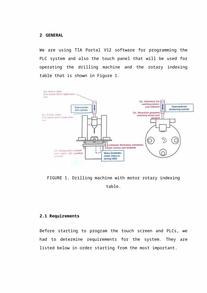
We are using TIA Portal V12 softwware for programming the PLC system and also the
touch panel that will be used for operating the drilling machine and the rotary
indexing table that is shown in Figure 1.
FIGURE 1. Drilling machine with motor rotary indexing table.
2.1 Requirements
Before starting to program the touch screen and PLCs, we had to determine
requirements for the system. They are listed below in order starting from the most
important.
● For “emergency stop”, there must be a buttoon incorporated into the touch
screen, as well as a physical one for turning the drilling machine power off..
There is for two reasons: It is easier to find the buttoon in case of emergency
and if the touch panel goes broken, the physical buttoon will still be able to
making its purpose via the Siemens Simatic S7-300 PLCs. The physical buttoon

must be normally closed, it turns open when pressed and back to closed, when
the buttoon is rotated.
● The system must also follow the requirements for automatic and manual
operations.
● There must be on/off. status information for each switch command. It allows
the user to know clearly what the device must be used step by step.
● The system should be able to use for manual drilling. That means, there is
manual control operation screen in the touch panel.
● Buttoons should not be too small and narrow for fingers. There is a risk that the
user could touch a wrong buttoon by mistake.
● There could be graphical symbols in buttoons on the touch panel screens. For
users, it makes easier to operate the system, if they speaks diff.erent languages,
but not the system’s default language.
● The buttoons could transform their appearance when they are pressed. For
example, the buttoon changes a color or the text changes its font to bold. It
makes clear to a user that the touch panel works and it takes touch
commands.
Our goal is to make the system that follows the requirements.
2.2 Technical Details
For programming logic, we are using Siemens Simatic S7-300 PLCs and Step 7
softwware. The system uses the following devices for PLC:
HMI: OP 177B 6” PN/DP (touch panel)
CPU 31�F-2 DP (...6FF01...)
DI 16xDC24 (digital input)
DO 16xDC24/0.�A (digital output)
AI4/AO2x8Bit (analog input/output, currently not used)
Power source: DC24V PS307 �A

The system uses the sensors for gettoing status informations and with the physical
buttoon, they are connected in the PLC inputs. Outputs supplies the power to indexing
table (for rotating), drilling machine and its magnetic actuators. Input & output table
are shown in Table 1.

TABLE 1: Allocation map rotary indexing table (physical in- and outputs).
Type Device Description
I0.0 optic switching sensor part available
I0.1 limit switch sensor final drilling position reached
I0.2 part strained
I0.3 part released
I0.4 drill in lower position
I0.� drill in upper position
I0.6 emergency stop buttoon stops drilling
O4.1 rotary disk table motor rotating clockwise
O4.2 motor rotating counter-clockwise
O4.3 drilling machine drilling machine on
O4.4 magnetic actuator: part straining
O4.� magnetic actuator: drill down

3 OPERATIONS
The system starts from the home screen that is showed in Figure 2. You can see that it
is possible to add any graphic images and the date.
FIGURE 2. Home screen.
On home screen, the user can choose between automatic and manual operation.
When the buttoon is pressed, the screen switches.
3.1 Automatic Operation
The purpose is to make the drilling operation automatically that is shown in Figure 3.
With the touch panel, the user configures, how much parts will be drilled. Then, the
system calculates, how much the system steps must do and the operation begins.
Requirements:
● The start buttoon disabled when the system is running (drill on).
● The stop buttoon is disabled when the system is in initial state (drill off.).
● The screen would display current item number, the operation time leftw and
items completed.

FIGURE 3. Automatic operation steps.
Step 1:
Switching condition:
o control unit on
o system is initial state
o Flipflop “start” active AND switch sequence on
o part in slot
Action: rotary disk leftw turn by 90 degrees
Step 2:
Switching condition: drilling position reached
Action: part straining

Step 3:
Switching condition: part strained
Actions:
o drilling machine on
o drill down
Step 4:
Switching condition: drill down
Action: wait for 3 seconds
Step �:
Switching condition: waiting time 3 seconds over
Action: drill up on
Step 6:
Switching condition: drill reached upper position
Actions:
o drilling machine off.
o part straining off.
3.2 Manual Operation
We focused to make the manual operation that allows the user to operate almost
everything. Requirements are shown in below and partly in Figure 4.
● When going back to home screen, the drilling machine must shut down.
● The drill can go down only, when the upper sensor is active and lower sensor
isn’t.
● When the drill is down, the table can’t spin and strain parts.

● There would be the delay time and it starts when the drill is running. When 1�
seconds time leftw, the warning notification appears. When the delay time is
over, the drill shuts down.
● The screen would display current item number and items completed. There
would be a buttoon to start counting from the beginning.
FIGURE 4. Manual operation steps.
We use the colorful and tried to find symbolic buttoons for operating the drilling
machine and rotary spinning table that are shown in Figure �. It also shows the status
of the drilling machine and the magnetic actuator (for gettoing drill down/up). There is
also “active system” buttoon and status information for it that is normally “0” when
coming from the home screen. If someone pushes emergency stop buttoon, it turns to
zero and nothing is possible to operate before the physical buttoon is closed and “active
system” buttoon is pressed. You can see some manual operation logics in Figure 6 and

table for it in Figure 7. For every output, there must be configured own network for
each output.
FIGURE �. Manual operation screen.
FIGURE 6. Example of logics for the manual operation.

FIGURE 7. Table of HMI touch screen commands (M0.X) and outputs (Q4.X).

4 SUMMARY
The initial project goal was to familiarize with WinCC Flexible. This was the most
time-consuming section of the Advanced Project Work, accounting for � weeks of the
10 week course. This centered around using local resources to summarize logic design
from start to finish. This information was supplemented with free online resources
that demonstrated more application-specific needs, such as touch screen panel
structure.
However, the project taught to apply the PLC with touch screen and we could
improve the system always bettoer for diff.erent applications. For example, the
automatic operation would be more challenging to program than manual, because it
requires to know exactly where the drill and rotor are in free space, as well as react to
“system shocks” that could disrupt the drilling operation. These additional
requirements will be dealt with in the coming weeks.