apsin6010-20g user manual v1.2 2010 · 2011-10-07 · apsin6010-20g user manual v1.2 2010 - |...
TRANSCRIPT

APSIN6010-20G User Manual V1.2 2010
- | Introduction to the APSIN 1
APSIN20G-6010 User’s Manual
Version 1.2, May 2011 Copyright This manual is copyright by AnaPico AG and all rights are reserved. No portion of this document may be reproduced, copied, transmitted, transcribed stored is a retrieval system, or translated in any form or by any means. Electronic, mechanical, magnetic, optical, chemical, manual or otherwise, without written permission of AnaPico AG. AnaPico and the AnaPico logo are internationally registered trademarks of AnaPico AG. AnaPico acknowledges the following product names as trademarks of their respective owners: Microsoft, Windows, LabVIEW, MATLAB. Disclaimer AnaPico AG makes no representation or warranties with respect to the contents hereof and specifically disclaims any implied warranties of merchantability for any particular purpose. AnaPico AG reserves the right to revise this publication and to make changes from time to time in the content thereof without obligation of AnaPico AG to notify any person of such revision or change.
APSIN6010-20G User Manual V1.2 2010
- | Introduction to the APSIN 2
Contents 1. Introduction to the APSIN .............................................................................4
General Features and Functions ........................................................................... 4 Options ......................................................................................................... 4 Front Panel Overview ........................................................................................ 5 Rear Panel Connections ..................................................................................... 7
2. Getting Started ..........................................................................................9 System Requirements ........................................................................................ 9 Unpacking the APSIN ........................................................................................ 9 Initial Inspection .............................................................................................. 9 Starting the APSIN ............................................................................................ 9 Applying Power ............................................................................................... 9 Connecting to LAN ......................................................................................... 10 Direct connectivity to host via Ethernet cable (no router) ......................................... 10 Connecting though USBTMC ............................................................................. 10 Installing the APSIN Remote Client ..................................................................... 10 Troubleshooting the LAN Interconnection ............................................................ 11 Shutting Down the APSIN ................................................................................ 11
3. Using the Graphical User Interface (GUI) .............................................................. 12 Start the APSIN GUI ........................................................................................ 12 Simultaneously controlling Multiple Signal Generators from one PC ........................... 13 Network Configuration ................................................................................... 13 Perform Firmware Upgrade .............................................................................. 14 Store and Revoke Instrument States ................................................................... 14 Using Toolbars .............................................................................................. 15 Basic CW Operation ........................................................................................ 16 Sweeps........................................................................................................ 17 Frequency Sweep (Figure 7) .............................................................................. 17 Frequency Linear Sweep .................................................................................. 17 Frequency Log Sweep ..................................................................................... 18 Frequency Random Sweep ............................................................................... 18 Power Sweep (Figure 8) ................................................................................... 18 List Sweeps (Figure 9) ..................................................................................... 19 Modulation Control ........................................................................................ 22 Reference ..................................................................................................... 25 Using the Trigger options (Figure 15) ................................................................... 26 LF OUT Control .............................................................................................. 28 Combined Modulation ..................................................................................... 29
4. Local Operation (HC Option) ............................................................................. 30 Displayed Parameter Formats ............................................................................ 31 CW Display ................................................................................................... 31 Main Menu Display ........................................................................................ 31 Frequency Sweep Submenu .............................................................................. 32 Power Sweep Submenu ................................................................................... 33 List Sweep Submenu ....................................................................................... 35

APSIN6010-20G User Manual V1.2 2010
- | Introduction to the APSIN 3
Modulation Submenu ..................................................................................... 35 Pulse Mod Submenu ....................................................................................... 36 Amplitude Mod Submenu ................................................................................ 36 Frequency Mod Submenu ................................................................................. 37 Reference Submenu ........................................................................................ 37 Trigger Submenu ........................................................................................... 38 LF OUTPUT Submenu ...................................................................................... 38 LAN Configuration Submenu ............................................................................ 39 Display Settings Submenu ................................................................................ 40 Default Settings Submenu ................................................................................ 40
5. Programming the APSIN ............................................................................. 42 Using Sockets LAN .......................................................................................... 42 Using and Configuring VXI-11 ............................................................................ 43 Using SCPI for APSINX000 ................................................................................ 43 Using Telnet LAN ........................................................................................... 43
6. Battery Operation (B3 Option) ..................................................................... 45 7. Extended Power Range (PE/PE2 Options) ........................................................ 48 8. Maintenance and Warranty Information ........................................................ 49
Adjustments and Calibration ............................................................................. 49 Repair ......................................................................................................... 49 Safety ......................................................................................................... 49 Warranty Information ..................................................................................... 50 Equipment Returns ......................................................................................... 50 Company Details ............................................................................................ 51
APSIN6010-20G User Manual V1.2 2010
- | Introduction to the APSIN 4
1. Introduction to the APSIN
Your APSIN Signal generator kit contains the following items:
APSIN mainframe
Universal power adaptor (AC 100 – 240V) with UK, US, EU plugs
Ethernet Cable
APSIN manuals & software CD
It is strongly recommended to use the original power adaptor (as supplied with the device) to
guarantee save and reliable operation of the APSIN.
General Features and Functions The Anapico APSIN RF & Microwave Signal Generator offers:
APSIN6010: 9 kHz to 6100 MHz frequency range (settable to 6400 MHz)
APSIN20G: 10 MHz to 20’000 MHz frequency range (settablefrom 9 kHz to 20’500 MHz)
–30 to +13 dBm power levelled range (APSIN6010), extendable to -100 and -130 dBm
with option PE and PE2, respectively.
-20 to + 13 dBm (APSIN20G), extendable to -90 and -120 dBm with option PE and PE2,
respectively.
Modulation capabilities for FM, PM, AM and pulse modulation
Fast frequency, power and list sweeps
Light weight, optional internal rechargeable batteries (option B3)
3- inch status LCD
Long-term support: Software upgrades (firmware and PC based) are available to download from www.anapico.com. You can also call our technical specialists for support. You can continue to use both of these services free of charge for the lifetime of the product.
USB 2.0 device and host interface
Universal LAN interface
18 months calibration cycle
Options B3: internal rechargeable battery
PE for APSIN6010: extended power range (-100 to +11 dBm)
PE for APSIN20G: extended power range (-90 to +13 dBm)
PE2 for APSIN6010: extended power range (-130 to + 13 dBm)
PE2 for APSIN20G: extended power range (-120 to + 13 dBm)
RM: 19’’ rack mount kit
APSIN6010-20G User Manual V1.2 2010
- | Introduction to the APSIN 5
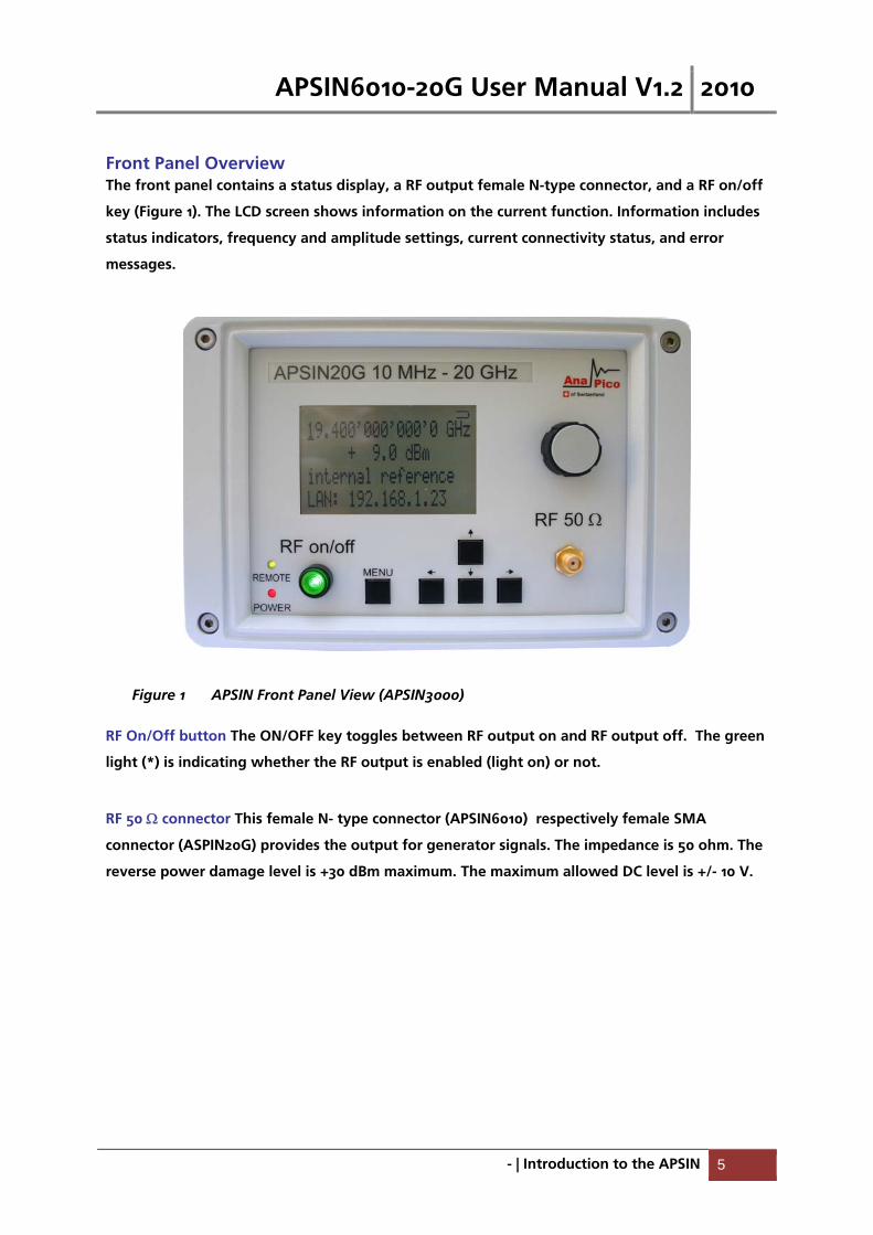
Front Panel Overview The front panel contains a status display, a RF output female N-type connector, and a RF on/off
key (Figure 1). The LCD screen shows information on the current function. Information includes
status indicators, frequency and amplitude settings, current connectivity status, and error
messages.
Figure 1 APSIN Front Panel View (APSIN3000)
RF On/Off button The ON/OFF key toggles between RF output on and RF output off. The green
light (*) is indicating whether the RF output is enabled (light on) or not.
RF 50 connector This female N- type connector (APSIN6010) respectively female SMA
connector (ASPIN20G) provides the output for generator signals. The impedance is 50 ohm. The
reverse power damage level is +30 dBm maximum. The maximum allowed DC level is +/- 10 V.
APSIN6010-20G User Manual V1.2 2010
- | Introduction to the APSIN 6
Displayed Parameter Formats
Main LCD display There are two parameters displayed in the main menu:
frequency in Hz (1st line) and
RF amplitude in dBm (2nd line).
On the 3rd line the lock status to an external reference source or enabled modulation format is
displayed.
The 4th line provides remote connectivity status of the controlled source. The display is updated
each time a value is changed.
Frequency - The current value for center frequency. Units: Hz
Range: 9’000 to 6’100’000’000 Hz (APSIN6010) resp. 20’000’000’000 Hz (APSIN20G)
Resolution: 0. 1 Hz
Amplitude - The current value for output power. Units: dBm
Range: -70.0 to +25.0 dBm (option PE/PE2: -150.0 to + 25.0 dBm)
Resolution 0.1 dB
Phase lock – External reference disabled, not locked or locked to pre-set value and enabled
modulation settings.
Range: 1 to 220 MHz
Connectivity – Status indication - The current LAN IP address of the instrument or USB-TMC
connection identifier.
APSIN6010-20G User Manual V1.2 2010
- | Introduction to the APSIN 7
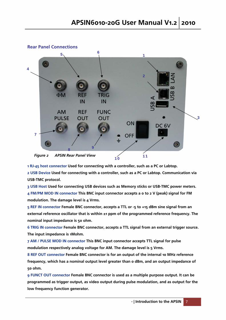
Rear Panel Connections
Figure 2 APSIN Rear Panel View
1 RJ-45 host connector Used for connecting with a controller, such as a PC or Labtop.
2 USB Device Used for connecting with a controller, such as a PC or Labtop. Communication via
USB-TMC protocol.
3 USB Host Used for connecting USB devices such as Memory sticks or USB-TMC power meters.
4 FM/PM MOD IN connector This BNC input connector accepts a 0 to 2 V (peak) signal for FM
modulation. The damage level is 4 Vrms.
5 REF IN connector Female BNC connector, accepts a TTL or -5 to +15 dBm sine signal from an
external reference oscillator that is within ±1 ppm of the programmed reference frequency. The
nominal input impedance is 50 ohm.
6 TRIG IN connector Female BNC connector, accepts a TTL signal from an external trigger source.
The input impedance is 1Mohm.
7 AM / PULSE MOD IN connector This BNC input connector accepts TTL signal for pulse
modulation respectively analog voltage for AM. The damage level is 5 Vrms.
8 REF OUT connector Female BNC connector is for an output of the internal 10 MHz reference
frequency, which has a nominal output level greater than 0 dBm, and an output impedance of
50 ohm.
9 FUNCT OUT connector Female BNC connector is used as a multiple purpose output. It can be
programmed as trigger output, as video output during pulse modulation, and as output for the
low frequency function generator.
4
10 11
1 5 6
7
8 9
2
3

APSIN6010-20G User Manual V1.2 2010
- | Introduction to the APSIN 8
10 Power switch The power switch disconnects the signal generator from the DC input
completely, including the internal high-stability reference. After switching on this switch, the
signal generator enters into standby with the OCXO warming up and RF out switched off. The
red power LED (option HC only) on the front panel is turned on.
11 DC IN power receptacle The power receptacle accepts a two-pin plug from the external 6 V
DC power adapter
APSIN6010-20G User Manual V1.2 2010
- | Getting Started 9
2. Getting Started
System Requirements
To ensure that your APSIN signal generator operates correctly with the graphical user interface,
you must have a computer with at least the minimum system requirements to run one of the
supported operating systems.
Operating system Windows™ 2000 SP4, XP SP2, Vista, or Windows 7
Ethernet Port 10/100/1000M Ethernet
Unpacking the APSIN
Remove the APSIN materials from the shipping containers. Save the containers for future use.
The standard APSIN package includes:
1 Synthesized Signal Generator
1 Ethernet Cable
1 Universal DC power adapter
1 APSIN Software & Manual CD
Initial Inspection Inspect the shipping container for damage. If container is damaged, retain it until contents of
the shipment have been verified against the packing list and instruments have been inspected
for mechanical and electrical operation.
Starting the APSIN This section describes installation instructions and APSIN verification tests.
Applying Power 1. Place the APSIN on the intended workbench and connect the appropriate DC power supply to
the receptacle on the rear of the unit. Make sure you use the included DC power supply. The
APSIN requires 6 V DC at 3 A maximum. Using other supplies may lead to malfunction and
damage of the APSIN.
2. Press the Line on/off switch on the rear panel. The front panel display will illuminate. The
instrument will initialize, and momentarily display the model number, firmware revision and
product serial number. The display will then switch to the factory default display setting,
showing preset frequency (100 MHz) and power (0.0 dBm), phase lock status (internal reference)
and instrument connectivity status (IP or USB identifier).
APSIN6010-20G User Manual V1.2 2010
- | Getting Started 10
Connecting to LAN Connect the APSIN to your local area network (LAN) or directly to your PC/Labtop using the
Ethernet cable. By default, the instrument is configured to accept its dynamic IP number from
the DHCP server of your network. If configured properly, your network router will assign a
dynamic IP number to the instrument which automatically will be displayed on the screen. Your
instrument is now ready to receive remote commands.
Direct connectivity to host via Ethernet cable (no router) If you want to connect the instrument directly to your computer (without router in the LAN),
you must use an Ethernet cable with crossover (not required if your computer has Gigabit-
Ethernet). To work properly, the network card (NIC) of your computer shall be set to a fixed IP
beginning with 169.xxx.xxx.xxx. In general, connection with a NIC that is configured to use
DHCP is also possible, but depending on the configuration the connection may take several
minutes.
After a short time, the instrument will detect that no DHCP server is present and assign itself a
default IP number 169.254.5.5. The instrument now must show 169.254.5.5 on the display.
Should the IP not appear after more than 30 seconds, leave the LAN cable in place and turn the
instrument off and then on again and retry.
Connecting though USBTMC
Connect the APSIN to the PC using the USB cable. The PC must be configured with a
VISA runtime environment (NI or Agilent, or comparable). If connected properly, the
VISA will detect the APSIN6010 and you can use VISA Write to send the *IDN? query and
use VISA Read to get the response. The USBTMC protocol supports service request,
triggers and other GPIB specific operations. The APSIN remote client (graphical user
interface) will detect all attached devices automatically.
Installing the APSIN Remote Client AnaPico’s graphical user interface provides an intuitive control of the APSIN. It runs under
Windows™ operating system with minimum requirements. The DLL is embedded in the GUI
application and requires the Microsoft® .NET™ framework to be installed. To install the GUI on
the computer, insert the APSIN Software and Manual CD into the CD/DVD drive. If the setup
doesn’t start automatically double click on the setup.exe to run the auto-installer.
The self-extracting setup provides easy installation and de-installation of the software. The
setup program guides you in a few steps though the installation process. In case the .NET
framework is not installed on your current Windows™ operating system, the setup procedure
automatically will assist you to install the required version. For this you will need an active
internet connection.
APSIN6010-20G User Manual V1.2 2010
- | Getting Started 11
Troubleshooting the LAN Interconnection Software does not install properly
Make sure your installation CD is not damaged.
When Microsoft .NET Framework is not installed make sure that your PC is to the
internet connected during installation of the APSIN Software. If no internet connection
is available, install the .NET™ Framework that is available on the installation CD.
Software cannot detect any APSIN
Make sure you have connected both PC and APSIN instrument to a common network.
If a direct connection is used, make sure you use an appropriate crossover Ethernet
cable (10 and 100Mbit LAN only). Note that detection of the APSIN can take a
considerable amount of time if your PC is configured to work with an external DHCP
server. In some cases the connection may even fail completely. Use a fixed IP instead.
Make sure that your software firewall enables the APSIN software to setup a TCP/IP
connection within the LAN. Under Windows XP you can do that like this:
Open Control Panel under Settings in your Start menu. Then go to Windows Firewall.
Click on Exceptions and then add Program. If the APSIN Software is in this list choose it
and click OK otherwise you have to browse for the path to AnaPico Software. Finally
close all open dialogs with OK. Now your Windows™ Firewall is ready for APSIN.
Shutting Down the APSIN Press the Line on/off switch on the rear panel to off.
APSIN6010-20G User Manual V1.2 2010
- | 3. Using the Graphical User Interface (GUI) 12
3. Using the Graphical User Interface (GUI)
AnaPico’s graphical user interface provides an intuitive control of the APSIN. It runs under any
Windows™ operating system. Make sure the software is installed correctly and the computer’s
firewall configured properly. The APSIN dynamic link library (DLL) uses the Microsoft .NET
framework.
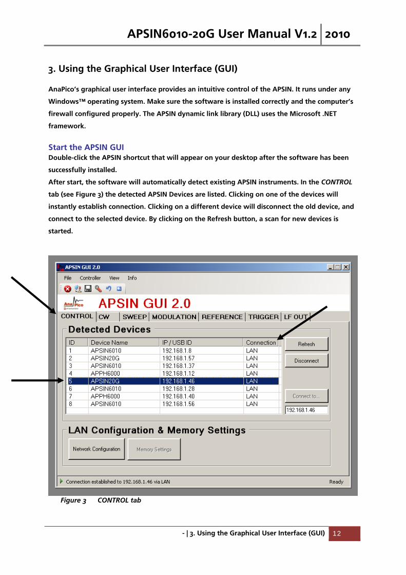
Start the APSIN GUI Double-click the APSIN shortcut that will appear on your desktop after the software has been
successfully installed.
After start, the software will automatically detect existing APSIN instruments. In the CONTROL
tab (see Figure 3) the detected APSIN Devices are listed. Clicking on one of the devices will
instantly establish connection. Clicking on a different device will disconnect the old device, and
connect to the selected device. By clicking on the Refresh button, a scan for new devices is
started.
Figure 3 CONTROL tab
APSIN6010-20G User Manual V1.2 2010
- | 3. Using the Graphical User Interface (GUI) 13
Alternatively, the IP address of an APSIN instrument can also be typed directly at the lower
right of the CONTROL tab.. This may be necessary if the instrument is working in a LAN
environment, where broadcast massages are blocked and the GUI auto detect function may fail.
Simultaneously controlling Multiple Signal Generators from one PC
You can easily control multiple APSIN from a single computer over the LAN connection, but you
need to start a separate GUI for every instrument.
Network Configuration
If your network does not have a DHCP server or a static IP address is preferred, you can set an IP
address, network mask and default route. The address and mask settings are required. The
default route is not strictly necessary, but enables network communication between the test set
and devices on a subnet other than that to which it is immediately attached. The network
features can be used on the local area network, even if no default route (specified as 0.0.0.0) is
configured.
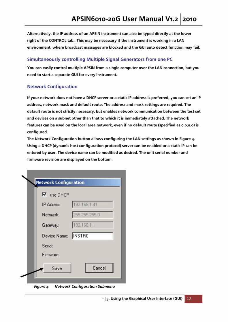
The Network Configuration button allows configuring the LAN settings as shown in Figure 4.
Using a DHCP (dynamic host configuration protocol) server can be enabled or a static IP can be
entered by user. The device name can be modified as desired. The unit serial number and
firmware revision are displayed on the bottom.
Figure 4 Network Configuration Submenu
APSIN6010-20G User Manual V1.2 2010
- | 3. Using the Graphical User Interface (GUI) 14
Perform Firmware Upgrade
A firmware upgrade of the APSINX000 can be done directly via the GUI. Make sure you are
connected to the right device and have the correct binary ready. Then go to Controller
Update Firmware and select the appropriate binary that you have received from AnaPico or
downloaded from the AnaPico website. The update will take a few seconds, and after
completion the device will reboot. Reconnect to the device and continue using the device.
Store and Revoke Instrument States
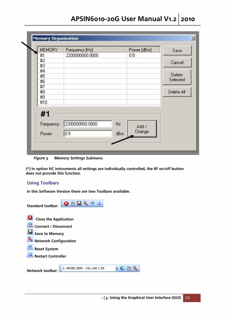
Ten different memory states are available to store the Frequency/Power pairs. By clicking on the
Memory Settings button, the currently saved memory settings are displayed and can be
modified as shown in Figure 5. To modify or enter a state, click on the appropriate line and
enter Frequency in Hz and Power in dBm.
Memory 1 is used as default state when the APSINX000 is powered up.
The 10 memory states can be accessed via the RF on/off button on the front panel. Press the RF
on/off button for about three seconds until the memory setting is displayed on the screen (*).
Release the button and browse through the ten memory states by pressing the RF on/off
button quickly. To select the currently displayed memory state, press the RF on/off button and
hold it for another three seconds. The instrument settings are updated from memory and the
display now shows the CW parameters.
APSIN6010-20G User Manual V1.2 2010
- | 3. Using the Graphical User Interface (GUI) 15
Figure 5 Memory Settings Submenu
(*) In option HC instruments all settings are individually controlled, the RF on/off button does not provide this function.
Using Toolbars
In this Software Version there are two Toolbars available.
Standard toolbar:
Close the Application
Connect / Disconnect
Save to Memory
Network Configuration
Reset System
Restart Controller
Network toolbar:

APSIN6010-20G User Manual V1.2 2010
- | 3. Using the Graphical User Interface (GUI) 16
device selection
Rescan devices
Connect / Disconnect
Network Configuration
Basic CW Operation The APSINX000 is a laboratory instrument designed to generate a synthesized CW signal with
good spectral purity and variable amplitude. To set a desired frequency, relative phase and
amplitude, click to the CW tab (Figure 6). The desired frequency, phase, and power can be set
by clicking on the up and down arrows above and below each digit. The frequency is settable in
steps of 0.001 Hz, the phase is settable in steps of 0.1 deg, and the power in steps of 0.1 dB.
The RF ON/OFF button turns the RF power on and off. The green LED in the RF ON button
indicates that the RF output is enabled.
The Save to Memory button allows you to save the current frequency/power pair to be stored
in one of the ten internal memory states.
Figure 6 CW tab
APSIN6010-20G User Manual V1.2 2010
- | 3. Using the Graphical User Interface (GUI) 17
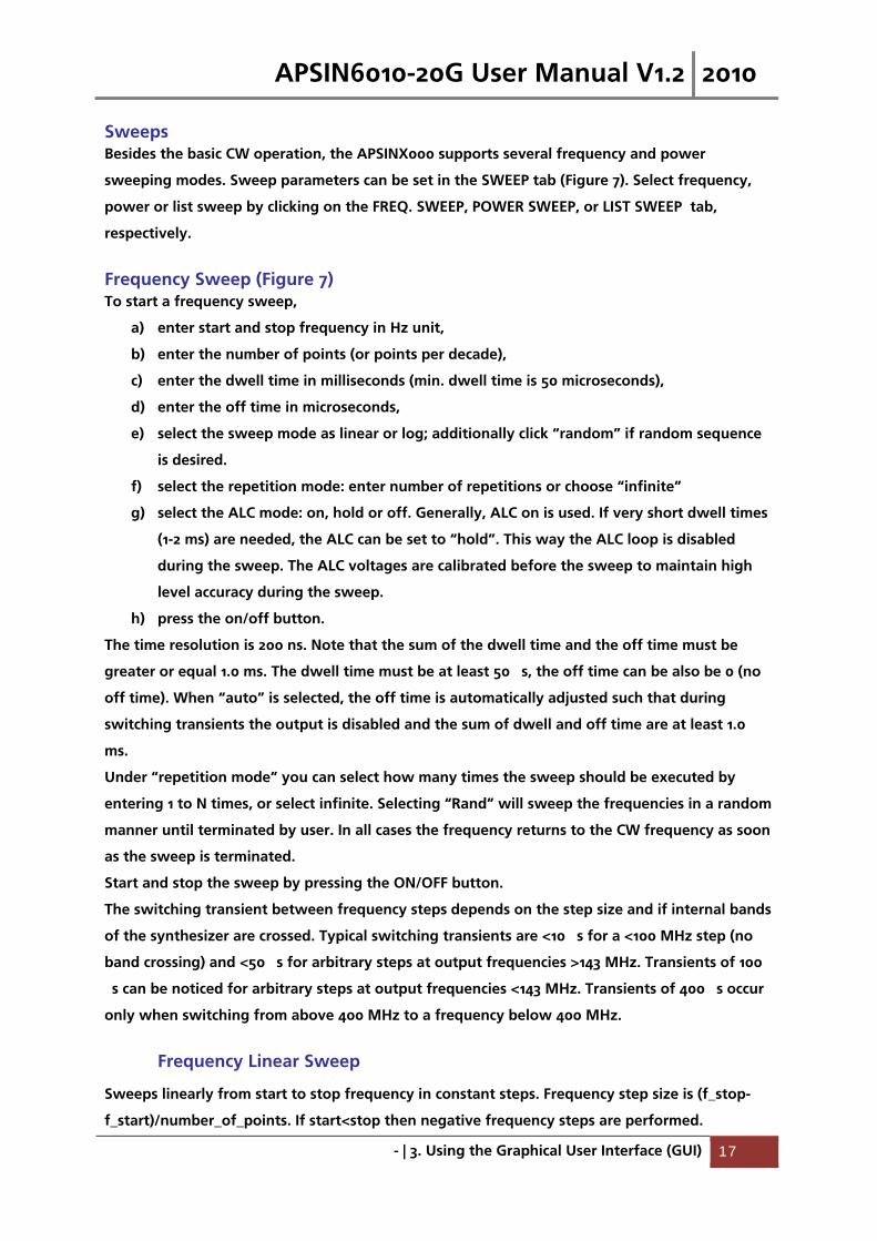
Sweeps Besides the basic CW operation, the APSINX000 supports several frequency and power
sweeping modes. Sweep parameters can be set in the SWEEP tab (Figure 7). Select frequency,
power or list sweep by clicking on the FREQ. SWEEP, POWER SWEEP, or LIST SWEEP tab,
respectively.
Frequency Sweep (Figure 7) To start a frequency sweep,
a) enter start and stop frequency in Hz unit,
b) enter the number of points (or points per decade),
c) enter the dwell time in milliseconds (min. dwell time is 50 microseconds),
d) enter the off time in microseconds,
e) select the sweep mode as linear or log; additionally click “random” if random sequence
is desired.
f) select the repetition mode: enter number of repetitions or choose “infinite”
g) select the ALC mode: on, hold or off. Generally, ALC on is used. If very short dwell times
(1-2 ms) are needed, the ALC can be set to “hold”. This way the ALC loop is disabled
during the sweep. The ALC voltages are calibrated before the sweep to maintain high
level accuracy during the sweep.
h) press the on/off button.
The time resolution is 200 ns. Note that the sum of the dwell time and the off time must be
greater or equal 1.0 ms. The dwell time must be at least 50 �s, the off time can be also be 0 (no
off time). When “auto” is selected, the off time is automatically adjusted such that during
switching transients the output is disabled and the sum of dwell and off time are at least 1.0
ms.
Under “repetition mode” you can select how many times the sweep should be executed by
entering 1 to N times, or select infinite. Selecting “Rand” will sweep the frequencies in a random
manner until terminated by user. In all cases the frequency returns to the CW frequency as soon
as the sweep is terminated.
Start and stop the sweep by pressing the ON/OFF button.
The switching transient between frequency steps depends on the step size and if internal bands
of the synthesizer are crossed. Typical switching transients are <10 �s for a <100 MHz step (no
band crossing) and <50 �s for arbitrary steps at output frequencies >143 MHz. Transients of 100
�s can be noticed for arbitrary steps at output frequencies <143 MHz. Transients of 400 �s occur
only when switching from above 400 MHz to a frequency below 400 MHz.
Frequency Linear Sweep
Sweeps linearly from start to stop frequency in constant steps. Frequency step size is (f_stop-
f_start)/number_of_points. If start<stop then negative frequency steps are performed.
APSIN6010-20G User Manual V1.2 2010
- | 3. Using the Graphical User Interface (GUI) 18
Frequency Log Sweep
Sweeps logarithmically from start to stop frequency in a given number of points per decade.
Frequency Random Sweep
The output frequency is selected randomly between start and stop frequency. The number of
different output frequencies is determined by the number of points selected by the user.
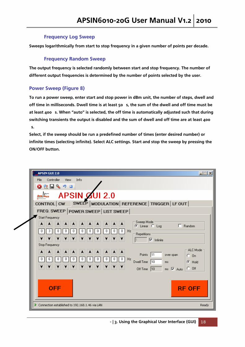
Power Sweep (Figure 8)
To run a power sweep, enter start and stop power in dBm unit, the number of steps, dwell and
off time in milliseconds. Dwell time is at least 50 �s, the sum of the dwell and off time must be
at least 400 �s. When “auto” is selected, the off time is automatically adjusted such that during
switching transients the output is disabled and the sum of dwell and off time are at least 400
�s.
Select, if the sweep should be run a predefined number of times (enter desired number) or
infinite times (selecting infinite). Select ALC settings. Start and stop the sweep by pressing the
ON/OFF button.

APSIN6010-20G User Manual V1.2 2010
- | 3. Using the Graphical User Interface (GUI) 19
Figure 7 FREQENCY SWEEP tab
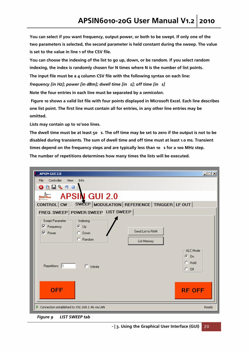
List Sweeps (Figure 9)
List sweeps allow to set frequency, output power, dwell time, and off time for each entry
individually. To start a list sweep, the following steps are required:
a) select sweep parameter
b) select indexing
c) upload list file from computer (CSV-file)
d) select number of repetition
e) select the ALC mode: on, hold or off. Generally, ALC on is used. If very short dwell times
(1-2 ms) are needed, the ALC can be set to “hold”. This way the ALC loop is disabled
during the sweep. The ALC voltages are calibrated before the sweep to maintain high
level accuracy during the sweep.
f) start sweep with on/off button
Figure 8 POWER SWEEP tab
APSIN6010-20G User Manual V1.2 2010
- | 3. Using the Graphical User Interface (GUI) 20
You can select if you want frequency, output power, or both to be swept. If only one of the
two parameters is selected, the second parameter is held constant during the sweep. The value
is set to the value in line 1 of the CSV file.
You can choose the indexing of the list to go up, down, or be random. If you select random
indexing, the index is randomly chosen for N times where N is the number of list points.
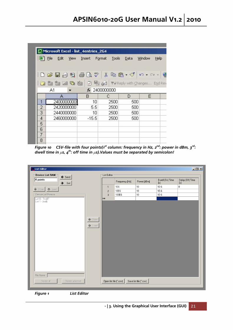
The input file must be a 4 column CSV file with the following syntax on each line:
frequency [in Hz]; power [in dBm]; dwell time [in �s]; off time [in �s]
Note the four entries in each line must be separated by a semicolon.
Figure 10 shows a valid list file with four points displayed in Microsoft Excel. Each line describes
one list point. The first line must contain all for entries, in any other line entries may be
omitted.
Lists may contain up to 10’000 lines.
The dwell time must be at least 50 �s. The off time may be set to zero if the output is not to be
disabled during transients. The sum of dwell time and off time must at least 1.0 ms. Transient
times depend on the frequency steps and are typically less than 10 �s for a 100 MHz step.
The number of repetitions determines how many times the lists will be executed.
Figure 9 LIST SWEEP tab
APSIN6010-20G User Manual V1.2 2010
- | 3. Using the Graphical User Interface (GUI) 21
Figure 10 CSV-file with four points(1st column: frequency in Hz, 2nd: power in dBm, 3rd:
dwell time in s, 4th: off time in s).Values must be separated by semicolon!
Figure 1 List Editor
APSIN6010-20G User Manual V1.2 2010
- | 3. Using the Graphical User Interface (GUI) 22
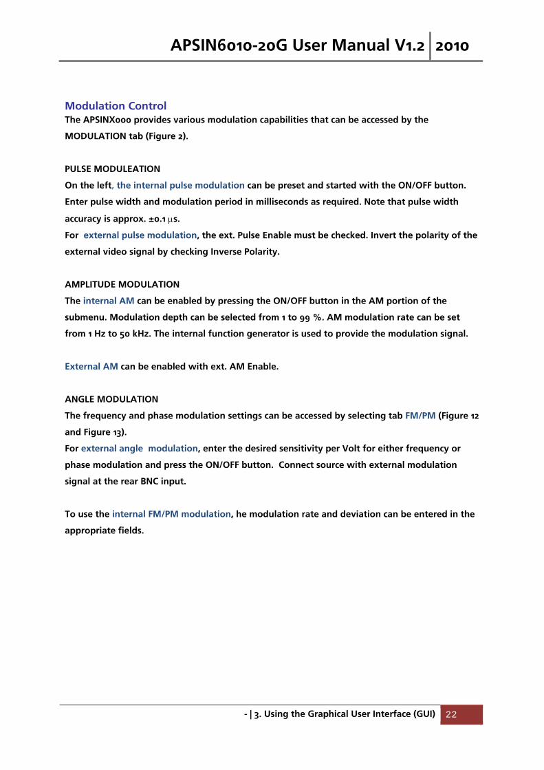
Modulation Control The APSINX000 provides various modulation capabilities that can be accessed by the
MODULATION tab (Figure 2).
PULSE MODULEATION
On the left, the internal pulse modulation can be preset and started with the ON/OFF button.
Enter pulse width and modulation period in milliseconds as required. Note that pulse width
accuracy is approx. ±0.1 s.
For external pulse modulation, the ext. Pulse Enable must be checked. Invert the polarity of the
external video signal by checking Inverse Polarity.
AMPLITUDE MODULATION
The internal AM can be enabled by pressing the ON/OFF button in the AM portion of the
submenu. Modulation depth can be selected from 1 to 99 %. AM modulation rate can be set
from 1 Hz to 50 kHz. The internal function generator is used to provide the modulation signal.
External AM can be enabled with ext. AM Enable.
ANGLE MODULATION
The frequency and phase modulation settings can be accessed by selecting tab FM/PM (Figure 12
and Figure 13).
For external angle modulation, enter the desired sensitivity per Volt for either frequency or
phase modulation and press the ON/OFF button. Connect source with external modulation
signal at the rear BNC input.
To use the internal FM/PM modulation, he modulation rate and deviation can be entered in the
appropriate fields.

APSIN6010-20G User Manual V1.2 2010
- | 3. Using the Graphical User Interface (GUI) 23
Figure 2 MODULATION tab for pulse and AM modulation
APSIN6010-20G User Manual V1.2 2010
- | 3. Using the Graphical User Interface (GUI) 24
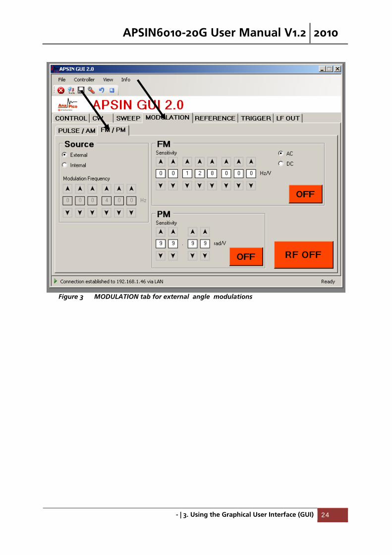
Figure 3 MODULATION tab for external angle modulations
APSIN6010-20G User Manual V1.2 2010
- | 3. Using the Graphical User Interface (GUI) 25
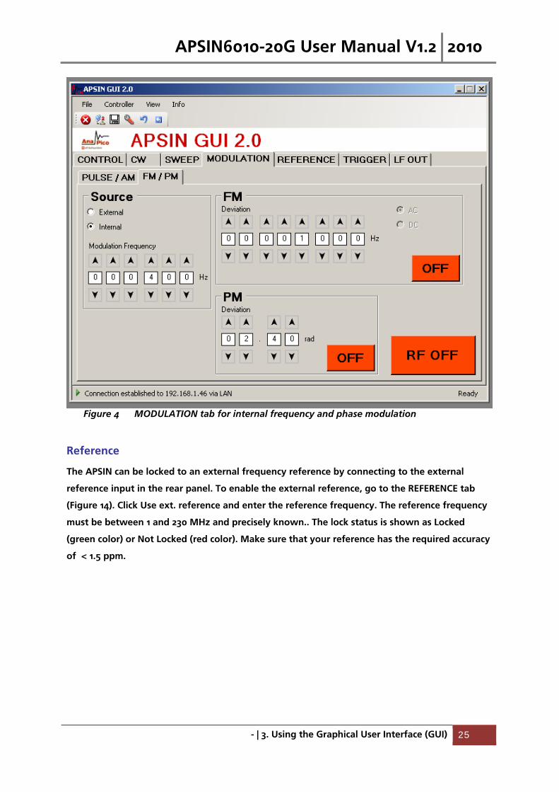
Figure 4 MODULATION tab for internal frequency and phase modulation
Reference
The APSIN can be locked to an external frequency reference by connecting to the external
reference input in the rear panel. To enable the external reference, go to the REFERENCE tab
(Figure 14). Click Use ext. reference and enter the reference frequency. The reference frequency
must be between 1 and 230 MHz and precisely known.. The lock status is shown as Locked
(green color) or Not Locked (red color). Make sure that your reference has the required accuracy
of < 1.5 ppm.
APSIN6010-20G User Manual V1.2 2010
- | 3. Using the Graphical User Interface (GUI) 26
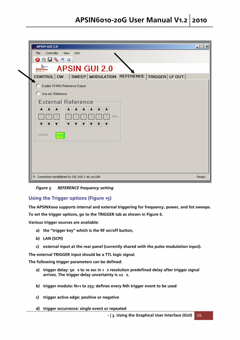
Figure 5 REFERENCE frequency setting
Using the Trigger options (Figure 15)
The APSINX000 supports internal and external triggering for frequency, power, and list sweeps.
To set the trigger options, go to the TRIGGER tab as shown in Figure 6.
Various trigger sources are available:
a) the “trigger key” which is the RF on/off button,
b) LAN (SCPI)
c) external input at the rear panel (currently shared with the pulse modulation input).
The external TRIGGER input should be a TTL logic signal.
The following trigger parameters can be defined:
a) trigger delay: 50 �s to 10 sec in 1 �s resolution predefined delay after trigger signal arrives. The trigger delay uncertainty is ±2 �s.
b) trigger modulo: N=1 to 255: defines every Nth trigger event to be used
c) trigger active edge: positive or negative
d) trigger occurrence: single event or repeated

APSIN6010-20G User Manual V1.2 2010
- | 3. Using the Graphical User Interface (GUI) 27
e) trigger type: single point, complete sweep, or gated
Confirm settings and arm trigger by pressing the Apply button.
As soon as a sweep is programmed, the output is disabled while the trigger is expected. Upon
arrival of the trigger the sweep is executed (after given trigger delay). Any trigger signal
arriving during execution of the sweep will be ignored.
If single sweep has been selected, the sweep will be executed only once as soon as first trigger
signal arrives. As soon as the sweep is completed, the frequency will return to the preset CW
frequency.
If repeat sweep is selected, the sweep will be executed every time the trigger signal arrives.
After the sweep is completed, the frequency the RF output is disabled until next trigger arrives.
With trigger type, the user can select the trigger either to execute only a single point from the
sweep or the complete sweep. When gated is selected the sweep is only executed while the
trigger signal is high.
Figure 6 TRIGGER tab

APSIN6010-20G User Manual V1.2 2010
- | 28
LF OUT Control The APSIN rear panel output FUNCT OUT can be programmed using the LF OUT tab (Figure 7).
The FUNCT OUT output can be used as
Video output of the internal pulse modulation signal
Trigger output
Output of the low frequency generator
In the GUI, select which output to be used and enable it by pressing the ON/OFF button.
The low frequency generator can output sine wave, triangle, or a square wave. The frequency
can be set from 1 Hz to 5 MHz. The amplitude of the sine wave and triangle can be set for the
sine wave and the triangle. If square wave is selected, the output is not affected by the
amplitude settings and gives constant 5 Volts peak-peak amplitude.
The output impedance for sine and triangle wave output is 50 ohms, for square wave, trigger
and pulse modulation video it is high impedance (CMOS and TTL logic compatible).
Figure 7 LF OUT tab

APSIN6010-20G User Manual V1.2 2010
- | 29
Combined Modulation
The table below shows what modulation types can be active simultaneously.
All modulation can be combined with frequency and power sweeps. For FM/PM, some timing
restrictions apply. Check programmer’s manual for further details.
Table 1: Possible combinations of internal and external modulation, and the internal LF generator output.
FM/PM
INT / EXT
AM
INT / EXT
PULSE
INT / EXT LF Generator
FM/PM
INTERNAL
EXTERNAL
YES / YES
YES / YES
YES / YES
YES / YES
YES
YES
AM
INTERNAL
EXTERNAL
YES / YES
YES / NO
NO
YES
PULSE
INTERNAL
EXTERNAL
YES
YES
LF Generator
Notes:
APSIN6010-20G User Manual V1.2 2010
- | 4. Local Operation (HC Option) 30
4. Local Operation (HC Option)
With the HC option, the instrument is controllable directly from the front panel. Moreover,
simultaneous control via front panel and GUI is possible.
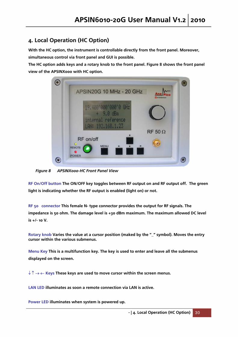
The HC option adds keys and a rotary knob to the front panel. Figure 8 shows the front panel
view of the APSINX000 with HC option.
Figure 8 APSINX000-HC Front Panel View
RF On/Off button The ON/OFF key toggles between RF output on and RF output off. The green
light is indicating whether the RF output is enabled (light on) or not.
RF 50� connector This female N- type connector provides the output for RF signals. The
impedance is 50 ohm. The damage level is +30 dBm maximum. The maximum allowed DC level
is +/- 10 V.
Rotary knob Varies the value at a cursor position (maked by the “_” symbol). Moves the entry cursor within the various submenus.
Menu Key This is a multifunction key. The key is used to enter and leave all the submenus
displayed on the screen.
Keys These keys are used to move cursor within the screen menus.
LAN LED illuminates as soon a remote connection via LAN is active.
Power LED illuminates when system is powered up.
APSIN6010-20G User Manual V1.2 2010
- | 4. Local Operation (HC Option) 31
Displayed Parameter Formats
This section describes how to edit the frequency and amplitude and how to invoke the
remaining functions of the APSINX000-HC in local mode.
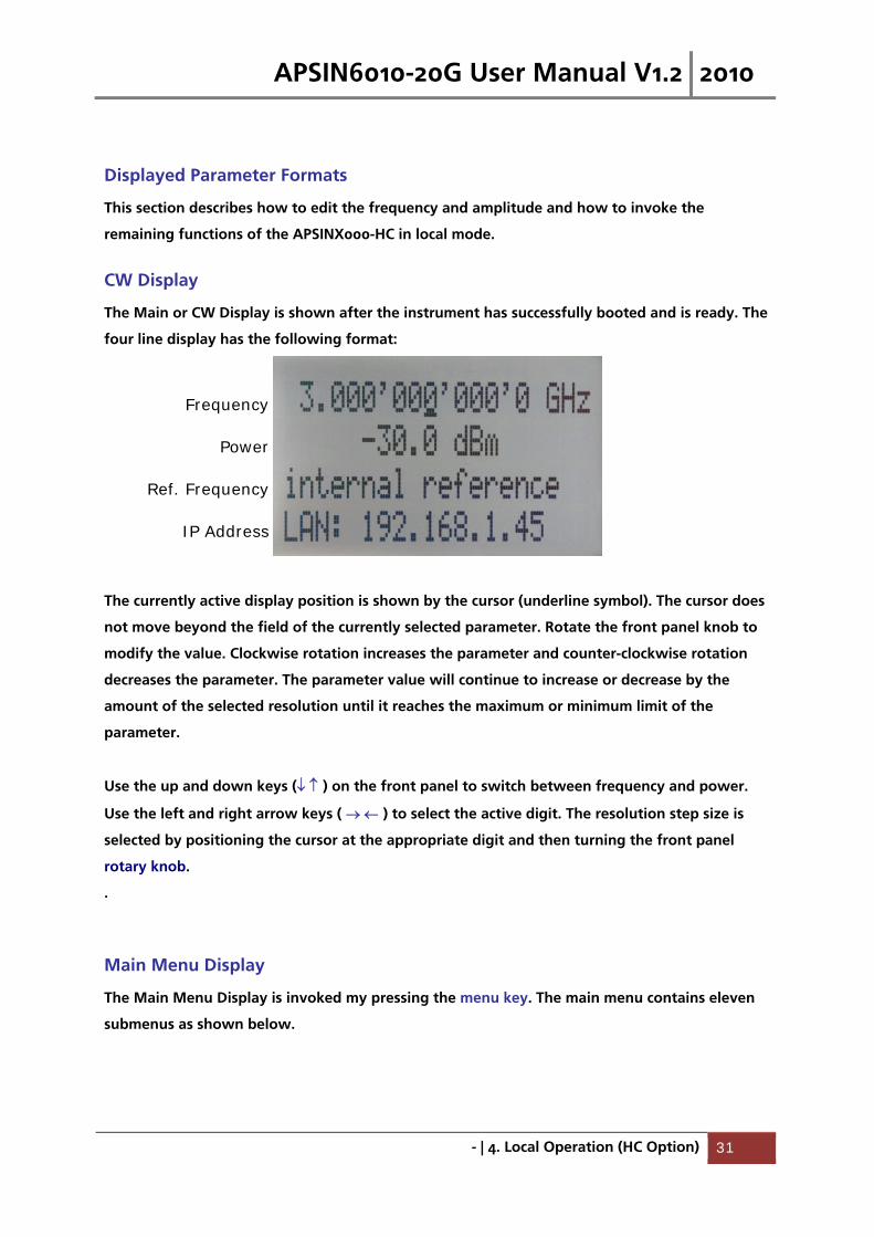
CW Display
The Main or CW Display is shown after the instrument has successfully booted and is ready. The
four line display has the following format:
The currently active display position is shown by the cursor (underline symbol). The cursor does
not move beyond the field of the currently selected parameter. Rotate the front panel knob to
modify the value. Clockwise rotation increases the parameter and counter-clockwise rotation
decreases the parameter. The parameter value will continue to increase or decrease by the
amount of the selected resolution until it reaches the maximum or minimum limit of the
parameter.
Use the up and down keys ( ) on the front panel to switch between frequency and power.
Use the left and right arrow keys ( ) to select the active digit. The resolution step size is
selected by positioning the cursor at the appropriate digit and then turning the front panel
rotary knob.
.
Main Menu Display
The Main Menu Display is invoked my pressing the menu key. The main menu contains eleven
submenus as shown below.
Frequency
Power
Ref. Frequency
IP Address

APSIN6010-20G User Manual V1.2 2010
- | 4. Local Operation (HC Option) 32
Figure 9 Overview of the submenus available on the display.
Use the up and down arrow keys ( ) or the rotary knob on the front panel to scroll the main
menu. The arrow on the left displays the selected position. To enter a submenu, move the
arrow (displayed at the left of the menu points) to the desired menu position and press the
menu key.
Frequency Sweep Submenu
After accessing the Frequency Sweep menu, first of three displays allows to enter the start and
stop frequency by using the keys to select the digits and using the rotary knob to increase
and decrease their values. Use the arrow to move between the several displays that contain
settable sweep parameters. On the second display, the number of points, and the on and off
time can be entered. On the third screen, select the sweep mode between LINear, LOGarithmic,
and RANDom. Also select the repetition mode between INFinite, and 1 (single repetition).

APSIN6010-20G User Manual V1.2 2010
- | 4. Local Operation (HC Option) 33
Start the sweep by pressing the RF On/Off button. The submenus can always been exited
(without starting the sweep) by pressing the menu key.
Figure 10 Displays shown for the frequency sweep configuration
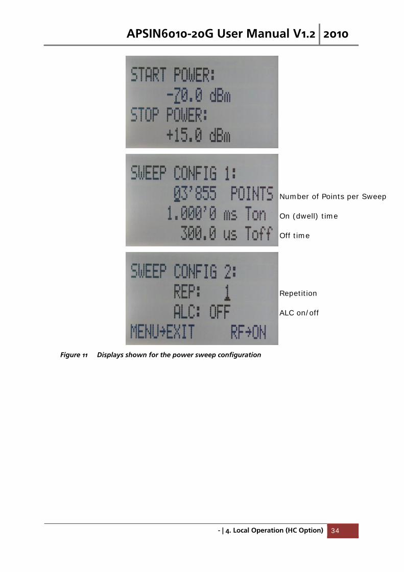
Power Sweep Submenu
After accessing the Power Sweep menu, the first of total three displays allow to enter start and
stop power by using the keys to select the digits and using the rotary knob to increase
and decrease their values. Use the arrow to move between the several displays that contain
settable sweep parameters. On the second display, the number of points, and the on and off
time can be entered. On the third display, select the repetition mode between INFinite, and 1
(single repetition).
Start the sweep by pressing the RF On/Off button. The submenu can always been exited
(without starting the sweep) by pressing the menu key.
Sweep Mode
Repetition
ALC on/off
Number of Points per Sweep
On (dwell) time
Off time
APSIN6010-20G User Manual V1.2 2010
- | 4. Local Operation (HC Option) 34
Figure 11 Displays shown for the power sweep configuration
Repetition
ALC on/off
Number of Points per Sweep
On (dwell) time
Off time
APSIN6010-20G User Manual V1.2 2010
- | 4. Local Operation (HC Option) 35
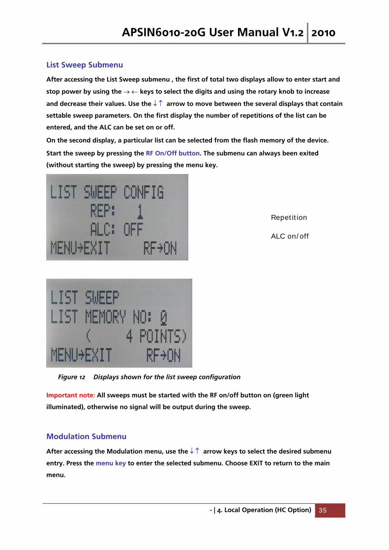
List Sweep Submenu
After accessing the List Sweep submenu , the first of total two displays allow to enter start and
stop power by using the keys to select the digits and using the rotary knob to increase
and decrease their values. Use the arrow to move between the several displays that contain
settable sweep parameters. On the first display the number of repetitions of the list can be
entered, and the ALC can be set on or off.
On the second display, a particular list can be selected from the flash memory of the device.
Start the sweep by pressing the RF On/Off button. The submenu can always been exited
(without starting the sweep) by pressing the menu key.
Figure 12 Displays shown for the list sweep configuration
Important note: All sweeps must be started with the RF on/off button on (green light
illuminated), otherwise no signal will be output during the sweep.
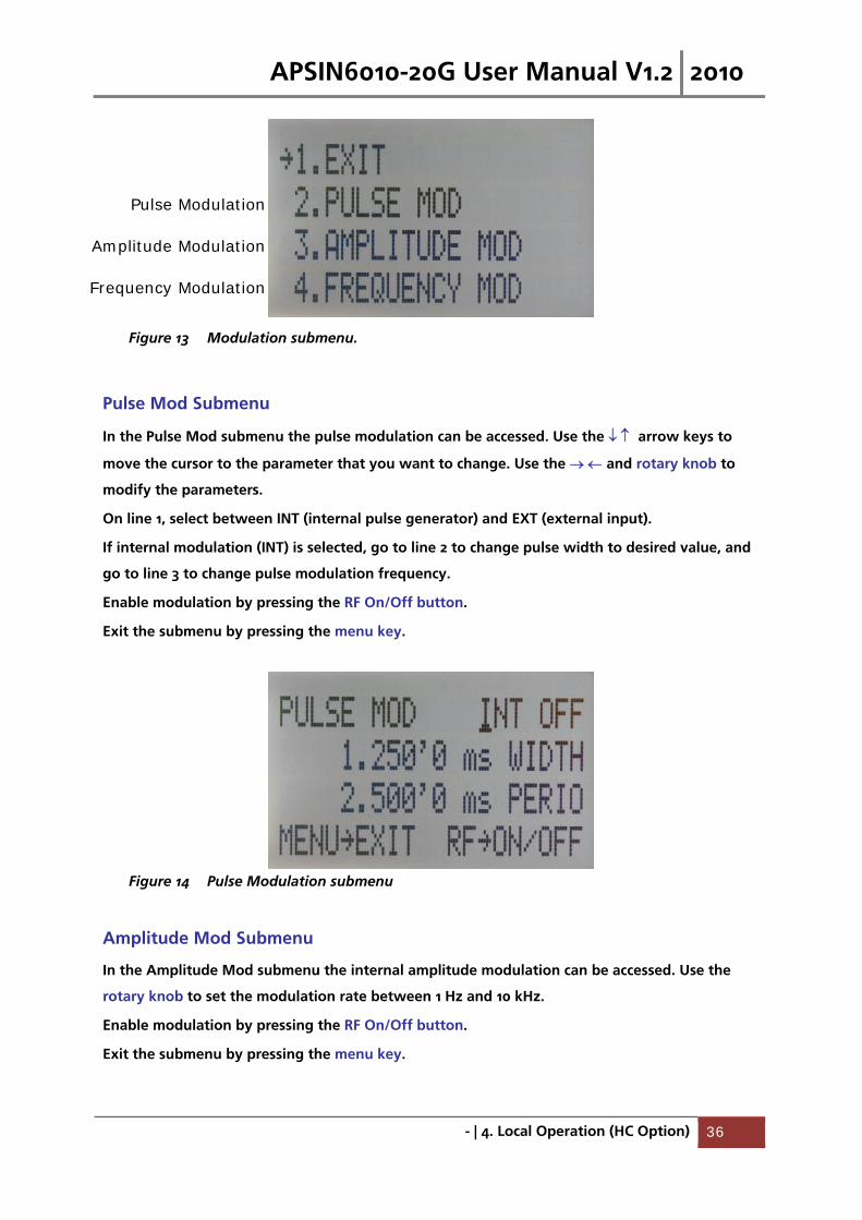
Modulation Submenu
After accessing the Modulation menu, use the arrow keys to select the desired submenu
entry. Press the menu key to enter the selected submenu. Choose EXIT to return to the main
menu.
Repetition
ALC on/off
APSIN6010-20G User Manual V1.2 2010
- | 4. Local Operation (HC Option) 36
Figure 13 Modulation submenu.
Pulse Mod Submenu
In the Pulse Mod submenu the pulse modulation can be accessed. Use the arrow keys to
move the cursor to the parameter that you want to change. Use the and rotary knob to
modify the parameters.
On line 1, select between INT (internal pulse generator) and EXT (external input).
If internal modulation (INT) is selected, go to line 2 to change pulse width to desired value, and
go to line 3 to change pulse modulation frequency.
Enable modulation by pressing the RF On/Off button.
Exit the submenu by pressing the menu key.
Figure 14 Pulse Modulation submenu
Amplitude Mod Submenu
In the Amplitude Mod submenu the internal amplitude modulation can be accessed. Use the
rotary knob to set the modulation rate between 1 Hz and 10 kHz.
Enable modulation by pressing the RF On/Off button.
Exit the submenu by pressing the menu key.
Pulse Modulation
Amplitude Modulation
Frequency Modulation
APSIN6010-20G User Manual V1.2 2010
- | 4. Local Operation (HC Option) 37
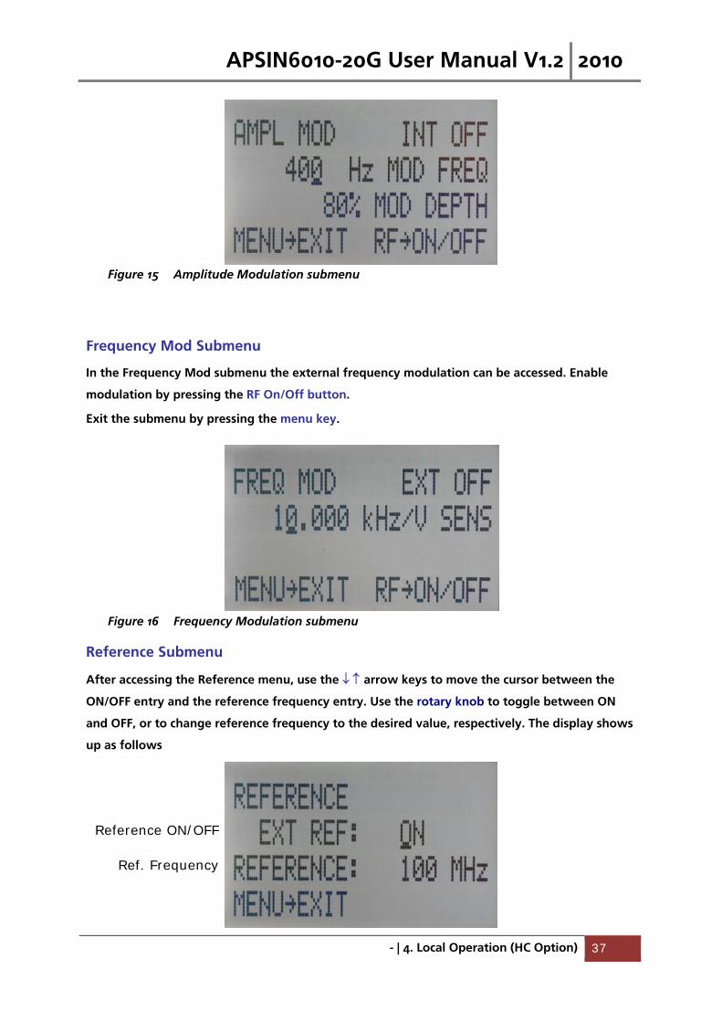
Figure 15 Amplitude Modulation submenu
Frequency Mod Submenu
In the Frequency Mod submenu the external frequency modulation can be accessed. Enable
modulation by pressing the RF On/Off button.
Exit the submenu by pressing the menu key.
Figure 16 Frequency Modulation submenu
Reference Submenu
After accessing the Reference menu, use the arrow keys to move the cursor between the
ON/OFF entry and the reference frequency entry. Use the rotary knob to toggle between ON
and OFF, or to change reference frequency to the desired value, respectively. The display shows
up as follows
Reference ON/OFF
Ref. Frequency

APSIN6010-20G User Manual V1.2 2010
- | 4. Local Operation (HC Option) 38
Figure 17 Reference submenu.
Confirm the setting by exiting the menu (pressing the menu key).
Trigger Submenu
After accessing the Trigger menu, use the arrow keys to move cursor between the
various menu entries. Use the rotary knob to toggle the selected entry value or to change
selected digit. The display shows up as follows.
Figure 18 Trigger submenu.
Select SOURce: IMMediate, EXTernal, BUS (SCPI command), KEY (RF on/off button)
Select SLOPe: POSitive, NEGative
Select CONTinuous: ON, OFF (ON means that the trigger is re-armed after each trigger
occurance)
Select RETRigger: OFF, ON, IMMediate (OFF means that any trigger event during execution of
list is ignored)
Enter DELAY: trigger delay in microseconds.
Press the RF On/Off button to arm the trigger. Exit the menu by pressing the menu key.
LF OUTPUT Submenu
In the LF OUTPUT Submenu the FUNCT OUT output at the rear panel of the instrument can be
configured.
Press the RF On/Off button to turn the output on and off. Exit the menu by pressing the menu
key.
On the first screen the source for the FUNCT OUT can be selected. Choose LFG for the low
frequency generator, TRIG to enable the internal trigger output, and PULM to enable the pulse
video output. If LFG is selected, use the arrow to proceed to the second display. Select
waveform between sine, triangle, or square. Then enter the desired output frequency and
voltage amplitude.
Trigger Source
Continues
Trigger Slope
Retrigger (on/off/immediate)
Trigger delay

APSIN6010-20G User Manual V1.2 2010
- | 4. Local Operation (HC Option) 39
Figure 19 Displays shown in the LF OUTPUT submenu
LAN Configuration Submenu
After accessing the LAN Configuration menu, use the arrow keys to move cursor between IP
address and submask address. Use the rotary knob to change selected digit. The display shows
up as follows.
Figure 20 LAN configuration submenu (display 1).
Once you have done changes as required, press the menu key to continue the configuration to
the second display. The display shows up as shown below:

APSIN6010-20G User Manual V1.2 2010
- | 4. Local Operation (HC Option) 40
Figure 21 LAN configuration submenu (display 2).
Use the rotary knob either enable (x) or disable ( ) DHCP. Finally, press the RF key to save the
configuration (don’t if you want to discard your changes). Press the menu key to exit the LAN
submenu.
Display Settings Submenu
After accessing the Display Configuration menu, use the rotary knob to change the display
contrast as required. Press the menu key to save and exit the Display Settings submenu.
Figure 22 Display settings submenu.
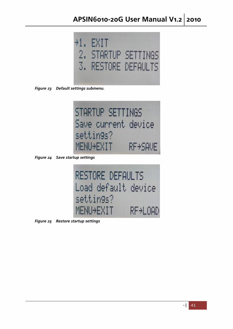
Default Settings Submenu
After accessing the Default Configuration menu, use the rotary knob to
Settings submenu.
APSIN6010-20G User Manual V1.2 2010
- | 41
Figure 23 Default settings submenu.
Figure 24 Save startup settings
Figure 25 Restore startup settings
APSIN6010-20G User Manual V1.2 2010
- | Programming the APSIN 42
5. Programming the APSIN
The signal generator can be remotely programmed via a 10/100/1000Base-T LAN interface and
LAN-connected computer using one of several LAN interface protocols. The LAN allows
instruments to be connected together and controlled by a LAN- based computer. LAN and its
associated interface operations are defined in the IEEE 802.2 standard.
The APSINX000 support the following LAN interface protocols:
1) Socket based LAN: proprietary function calls defined in the dynamic link library (DLL)
provided with the instrument, used for general programming using the LAN interface
under Windows operating system.
2) VXI-11/SCPI (version 1999) commands (firmware 2.0 upwards)
3) Telephone Network (TELNET): TELNET is used for interactive, one command at a time
instrument control
For LAN operation, the signal generator must be connected to the LAN, and an IP address must
be assigned to the signal generator either manually or by using DHCP client service. Your
system administrator can tell you which method to use. (Most current LAN networks use DHCP.)
DHCP Configuration
If the DHCP server uses dynamic DNS to link the hostname with the assigned IP address, the
hostname may be used in place of the IP address. Otherwise, the hostname is not usable.
Using Sockets LAN
Sockets LAN is a method used to communicate with the signal generator over the LAN interface
using the Transmission Control Protocol/Internet Protocol (TCP/IP). A socket is a fundamental
technology used for computer networking and allows applications to communicate using
standard mechanisms built into network hardware and operating systems. The method accesses
a port on the signal generator from which bidirectional communication with a network
computer can be established.
Sockets LAN can be described as an internet address that combines Internet Protocol (IP) with a
device port number and represents a single connection between two pieces of software. The
socket can be accessed using code libraries packaged with the computer operating system. Two
common versions of socket libraries are the Berkeley Sockets Library for UNIX systems and
Winsock for Microsoft operating systems.
Your signal generator implements a sockets Applications Programming Interface (API) that is
compatible with Berkeley socket for UNIX systems, and Winsock for Microsoft systems. The
signal generator is also compatible with other standard sockets APIs. The signal generator can
be controlled using predefined SCPI functions (available from firmware 2.0 upwards) use the
socket connection established in your program. Socket connection is available on port 18.
APSIN6010-20G User Manual V1.2 2010
- | Programming the APSIN 43
Using and Configuring VXI-11
The signal generator supports the LAN interface protocol described in the VXI- 11 standard. VXI-
11 is an instrument control protocol based on Open Network Computing/Remote Procedure Call
(ONC/RPC) interfaces running over TCP/IP.
A range of standard software such as NI-VISA or Agilent IO Config is available to setup the
computer/signal generator interface for the VXI- 11 protocol. Please refer to the applicable
software user manual and documentation for information on running the program and
configuring the VXI-11 interface. The program is used to configure the LAN client. Once the
computer is configured for a LAN client, you can use the VXI- 11 protocol and the VISA library to
send SCPI commands to the signal generator over the LAN interface. Example programs are
available on request under [email protected].
VISA is an IO library used to develop IO applications and instrument drivers that comply with
industry standards. It is recommended that the VISA library be used for programming the signal
generator. The NI-VISA and Agilent VISA libraries are similar implementations of VISA and have
the same commands, syntax, and functions.
Using SCPI for APSINX000
The Standard Commands for Programmable Instrumentation (SCPI) provides a uniform and
consistent language to control programmable test and measurement devices in instrumentation
systems. The SCPI Standard is built on the foundation of IEEE-488.2, Standard Codes and
Formats. It requires conformance to IEEE-488.2, but is pure software standard. SCPI syntax is
ASCII text, and therefore can be attached to any computer test language, such as BASIC, C, or
C++. It can also be used with Test Application Environments such as LabWindows/CVI,
LabVIEW™, or Matlab®. SCPI is hardware independent. SCPI strings can be sent over any
instrument interface. It works equally well over GPIB, RS-232, VXIbus or LAN networks.
Please see the APSINX000 Programmer’s Manual V 1.2 for detailed description of supported SCPI
commands.
Using Telnet LAN
Telnet provides a means of communicating with the signal generator over the LAN. The Telnet
client, run on a LAN connected computer, will create a login session on the signal generator. A
connection, established between computer and signal generator, generates a user interface
display screen with “>” prompts on the command line.
Using the Telnet protocol to send commands to the signal generator is similar to communicating
with the signal generator over LAN. You establish a connection with the signal generator and

APSIN6010-20G User Manual V1.2 2010
- | Programming the APSIN 44
then send or receive information using predefined commands. SCPI commands are supported
from firmware version 2.0. Communication is interactive: one command at a time. The telnet
service is available on port 18.
Please see the APSINX000 Programmer’s Manual for further details.
APSIN6010-20G User Manual V1.2 2010
- | Battery Operation (B3 Option) 45
6. Battery Operation (B3 Option)
If your APSINX000 is equipped with an internal rechargeable battery (B3 option) it can be
operated without the external power supply. Fully charged, the battery is good for up to three
hours of operation at full RF output power. The same external power adaptor (6 V @ 3 A) is
used for the battery version as for the standard APSINX000 for both normal operation and
charging of the battery.
There are four operating modes that are also summarized in Table 2 below:
normal operation– the external power supply is connected to the APSINX000 and the device is
turned ON (with the power switch on the rear panel turned ON). In this mode the APSINX000
can be used as if no battery was present. The internal battery is not used and will NOT be
charged.
charging – the external power supply is connected to the APSINX000 and the device is turned
OFF (with the power switch on the rear panel turned OFF). In this mode the APSINX000 is
charging the internal battery. Once the battery is fully charged, the APSINX000 goes into
standby mode. The time required to complete charging is approx. four hours.
standby – the internal battery is fully charged and the APSINX000 is turned OFF.
battery operation – the external power supply is disconnected and the device is turned ON. The
internal battery is supplying the power until it is exhausted.
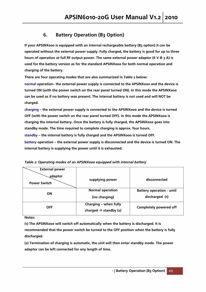
Table 2: Operating modes of an APSINX000 equipped with internal battery
External power
adaptor
Power Switch
supplying power
disconnected
ON Normal operation
(no charging)
Battery operation - until
discharged (1)
OFF Charging – when fully
charged standby (2) Completely powered off
Notes:
(1) The APSINX000 will switch off automatically when the battery is discharged. It is
recommended that the power switch be turned to the OFF position when the battery is fully
discharged.
(2) Termination of charging is automatic, the unit will then enter standby mode. The power
adaptor can be left connected for any length of time.
APSIN6010-20G User Manual V1.2 2010
- | Battery Operation (B3 Option) 46
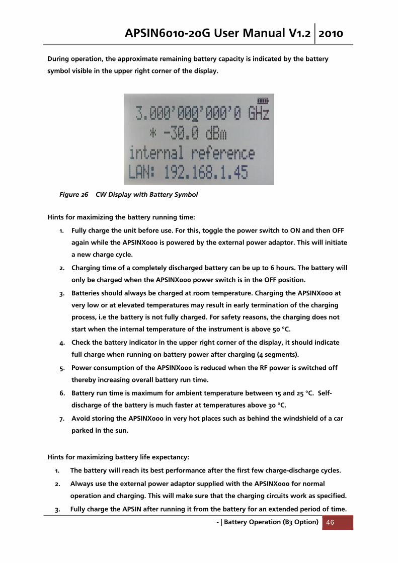
During operation, the approximate remaining battery capacity is indicated by the battery
symbol visible in the upper right corner of the display.
Figure 26 CW Display with Battery Symbol
Hints for maximizing the battery running time:
1. Fully charge the unit before use. For this, toggle the power switch to ON and then OFF
again while the APSINX000 is powered by the external power adaptor. This will initiate
a new charge cycle.
2. Charging time of a completely discharged battery can be up to 6 hours. The battery will
only be charged when the APSINX000 power switch is in the OFF position.
3. Batteries should always be charged at room temperature. Charging the APSINX000 at
very low or at elevated temperatures may result in early termination of the charging
process, i.e the battery is not fully charged. For safety reasons, the charging does not
start when the internal temperature of the instrument is above 50 °C.
4. Check the battery indicator in the upper right corner of the display, it should indicate
full charge when running on battery power after charging (4 segments).
5. Power consumption of the APSINX000 is reduced when the RF power is switched off
thereby increasing overall battery run time.
6. Battery run time is maximum for ambient temperature between 15 and 25 °C. Self-
discharge of the battery is much faster at temperatures above 30 °C.
7. Avoid storing the APSINX000 in very hot places such as behind the windshield of a car
parked in the sun.
Hints for maximizing battery life expectancy:
1. The battery will reach its best performance after the first few charge-discharge cycles.
2. Always use the external power adaptor supplied with the APSINX000 for normal
operation and charging. This will make sure that the charging circuits work as specified.
3. Fully charge the APSIN after running it from the battery for an extended period of time.
APSIN6010-20G User Manual V1.2 2010
- | Battery Operation (B3 Option) 47
4. If an APSIN with internal battery will be stored for a long period of time, fully charge it
before storage, then remove the power adaptor and make sure that the power switch is
in the OFF position. After storage, first charge the unit for 4-6 hours.
To replace the battery at the end of its lifetime, please contact AnaPico or one of its
distributors.
♦ Before using the APSIN in battery mode for the first time, the battery must be fully charged.
♦ Batteries must be disposed off according to the local environmental regulations.
APSIN6010-20G User Manual V1.2 2010
- | Extended Power Range (PE/PE2 Options) 48
7. Extended Power Range (PE/PE2 Options)
Both the APSIN3000 and the APSIN6000 are available with options extending the power range
towards lower power levels.
With these options installed, the minimum settable power level in CW operation is extended
down to –150 dBm. For the guaranteed minimum power level, please consult the respective
datasheet.
In POWER SWEEP Mode, the user shall avoid running sweeps over large power ranges (> 30 dB)
for extended periods of time, as this will result in continuous switching of the mechanical
attenuators and thus reduce the lifetime.
In sweeps where the mechanical attenuator is switched, the minimum dwell time increases to
20 ms.

APSIN6010-20G User Manual V1.2 2010
- | Maintenance and Warranty Information 49
8. Maintenance and Warranty Information
Adjustments and Calibration
To maintain optimum measurement performance, the APSINX000 should be calibrated every 24
months. It is recommended that the APSINX000 be returned to AnaPico or to an authorized
calibration facility. For more information please contact our Customer Service Department at
[email protected] or by phone (+4144) 440 00 51.
Repair
The signal generator contains no user-serviceable parts. Repair or calibration of the
signal generator requires specialised test equipment and must be performed by AnaPico or its
authorized repair specialists.
Safety
FCC notice This equipment has been tested and found to comply with the limits for a Class A device,
pursuant to Part 15 of the FCC Rules. These limits are designed to provide reasonable protection
against harmful interference when the equipment is operated in a commercial environment.
This equipment generates, uses, and can radiate radio frequency energy and, if not installed
and used in accordance with the instruction manual, may cause harmful interference to radio
communications.
Operation of this equipment in a residential area may cause harmful interference
in which case the user will be required to correct the interference at his or her own expense.
notice The APSINX000 Signal Generator meets the intent of the EMC directive 89/336/EEC and have
been designed to EN61326 Class A Emissions and Immunity standard.
The APSINX000 also meets the intent of the Low Voltage Directive and have been designed to
meet the IEC 61010-1:2001 (safety requirements for electrical equipment, control, and laboratory
use) standard.
APSIN6010-20G User Manual V1.2 2010
- | Maintenance and Warranty Information 50
Warranty Information
All AnaPico instruments are warranted against defects in material and workmanship for a
period of two years from the date of shipment. AnaPico will, at its option, repair or replace
products that prove to be defective during the warranty period, provided they are returned to
AnaPico and provided the preventative maintenance procedures are followed. Repairs
necessitated by misuse of the product are not covered by this warranty. No other warranties
are expressed or implied, including but not limited to implied warranties of merchantability and
fitness for a particular purpose. AnaPico is not liable for consequential damages.
The warranty on the internal rechargeable batteries (option B3) is one year from the date of
shipment. Battery replacement is available through AnaPico and its distributors.
Equipment Returns
For instruments requiring service, either in or out of warranty, contact your local distributor or
AnaPico Customer Service Department at the address given below for pricing and instructions
before returning your instrument.
When you call, be sure to have the following information available:
Model number.
Serial number.
Full description of the failure condition.
Note: Model and serial number can be found on the rear of the APSINX000 unit, next to the
power plug.
You will get a Return Mechandise Authorization (RMA) number from AnaPico, please put it on
the outside of the package.
Instruments that are eligible for in-warranty repair will be returned prepaid to the customer.
For all other situations the customer is responsible for all shipping charges. An evaluation fee
may be charged for processing units that are found to have no functional or performance
defects.
For out of warranty instruments, AnaPico will provide an estimate for the cost of repair.
Customer approval of the charges will be required before repairs can be made. For units
deemed to be beyond repair, or in situations where the customer declines to authorize repair,
an evaluation charge may be assessed by AnaPico.
APSIN6010-20G User Manual V1.2 2010
- | Maintenance and Warranty Information 51
Company Details
Address: AnaPico AG Parkring 57 8002 Zurich Switzerland Phone: +41 (44) 440 00 51 Fax: +41 (44) 440 00 50 Email: Technical Support: [email protected] Sales: [email protected] Web site: www.anapico.com