april i6th, 1942 mercedes-benz d.b - · pdf fileapril i6th, 1942 flight mercedes-benz d.b.601n...
TRANSCRIPT
APRIL I6TH, 1942 F L I G H T
MERCEDES-BENZ D.B.601N
3&5
EXAMINATION OF THE ENGINE FITTED TO THE Me 109F, Me 110, He 113,
AND MACCHI C200
By G. GEOFFREY SMITH, M.B.E. (Exclusive Illustrations by M. A, Millar)
SPECIMENS of the newest German liquid-cooled engine brought down over this country
•"-̂ L, have been stripped for inspection by aircraft engineers. By courtesy of the Ministry of Aircraft Production, Flighthas examined several of these engines captured intact, and is pleased to add details to the series of aircraft engines already reviewed in these columns. Features of the engine include a variable speed supercharger, direct petrol injection into each cylinder by mechanical pump and injectors, and the inverted V cylinder layout common to German ' ' inline ' ' engines, with provision for a cannon firing through the airscrew hub.
Famous aircraft engines which have been described and illustrated in Flight in recent months'include the Bristol Hercules (November 27th, 1941), the Rolls-Royce Merlin XX (February 26th, 1942), and the Allison C.15 (March 26th, 1942). Each engine represents the highest development in design in their particular class, the liquid-cooled "in-l ine" types, including engines produced in Britain and America respectively.
These detailed particulars of Germany's most noted engine of the liquid-cooled type—the Mercedes-Benz D.B.601N—provide students of design with information and lllus-
. ---(Rations from which many interesting comparisons of the power units of various countries can be made.
D.B.601N, of which some details of earlier examples brought down in this country were given in Flight of November 7th, 1940, differs most notably from the Merlin or Allison in
' that it is an inverted power unit, as indeed are all other service "in-line " engines of German origin. Its capacity of 33.9 litres (bore and stroke 150x160 mm.) is much larger than either the Merlin (27 litres) or the Allison (28.1 litres), but smaller than the fourteen-cylinder Hercules (38.7 litres). The net dry weight is 1,4001b. and with all accessories 1,5401b. Notable for its rugged design, the engine has a compression ratio of 7 9 to 1,
German engine designers have ^Uiays favoured large cylinder capacity and lower boost pressures than are employed on British engines. In other words, the power developed is little greater than our own engines of smaller capacity, put being larger they naturally present a greater frontal area than British engines. The
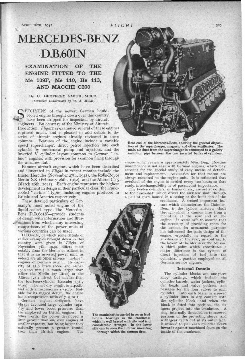
The crankshaft is carried in seven lead-bronze bearings in the crankcase, which is well braced with ribs and is of considerable strength. In the lower side can be seen the tubular mounting
through which the cannon fires.
Rear end of the Mercedes-Benz, showing the general disposition of the supercharger, magneto and other auxiliaries. The main air duct from the supercharger is connected to a gallery induction pipe between the two inverted banks of cylinders.
engine under review is approximately 68in. long. Routine maintenance is not easy with German engines, which may account for the special study of easy means of detachment and replacement. Auxiliaries for that reason are always mounted on the engine unit. It is estimated that overhaul of the engine is needed every 100 hours so that ready interchangeability is of paramount importance.
The twelve cylinders, in banks of six, are set at 60 deg. to the crankshaft which drives the airscrew shaft through a pair of gears housed in a casing at the front end of the
crankcase. A second important feature which characterises the Daimler-Benz is the hollow airscrew shaft through which a cannon fires from a mounting at the rear end of the engine. It seems safe to assume that the necessity of providing room for the cannon for armament purposes has influenced the basic design of the engine, especially in regard to the auxiliaries at the rear, in contrast to the layout of the Merlin or the Allison. A third point which constitutes a major difference is the system of direct injection of fuel into the cylinders, a practice employed on all German service engines.
Internal Details
The cylinder blocks are one-piece alloy castings, which include the cylinder barrels, water jackets, cylinder heads and valve pockets, and passages for the four valves to each cylinder. Into each barrel is screwed a cylinder liner in dry contact with the cylinder block, and when the block is fitted into position, the six liners project into the crankcase. A ring, internally threaded on to screwed portions of the projecting sleeve, and with'gear teeth cut in its outer face, is utilised to pull each cylinder sleeve inwards against machined faces on the inside of the crankcase.

366 FLIGHT A P R I L I 6 T H , 194?
M E R C E D E S - B E N Z D . B . 6 0 1 N
Thus the cylinder block, as a whole, is fixed to the crank-case by six rings per block, and there are no rubber gaskets, either in the block or in its assembly in the crankcase. In order to rotate the rings for assembly or dismantling, a special tool, fitted with a small gear wheel, is engaged with the gear teeth cu t in the rings and then rota ted by hand . The coolant circulated in the cylinder jackets is water, with the addition of 50 per cent, glycol as an anti-freeze.
The crankcase is of considerable depth, and the cover on top is a flat duralumin lid held in place by a number of small studs and nuts . A six-throw balanced crankshaft, weighing 150 lb. , runs in seven plain lead-bronze bearings, and each bearing structure is stiffened by a transverse rod qcross the crankcase webs above the bearings, and is retained by external nuts . The main bearing of each pair of connecting rods on the crankpin has three t racks of rollers (72 rollers per bearing), retained in split duralumin cages, bu t the single-blade connecting rod has a plain lead-bronze bearing only, over the outside of the roller bearing,
Elaborate precautions have been taken by special serrated joints in the halves of both forked and plain rods to register the bearings for accurate assembly and smooth working, and the retaining nuts are splined (not machined hexagonally) for special tools during assembly. Three compression and two scraper rings are fitted to each of the pistons, which have concave heads, and the gudgeon pins float in the piston bosses, domed ends being fitted to prevent scruffing of the cylinder walls. The gudgeon-pin phosphor-bronze bearings are a fixture in the connecting-rod small-ends.
The airscrew reduction gears are of normal design, bu t are contained in a very short and compact housing—•
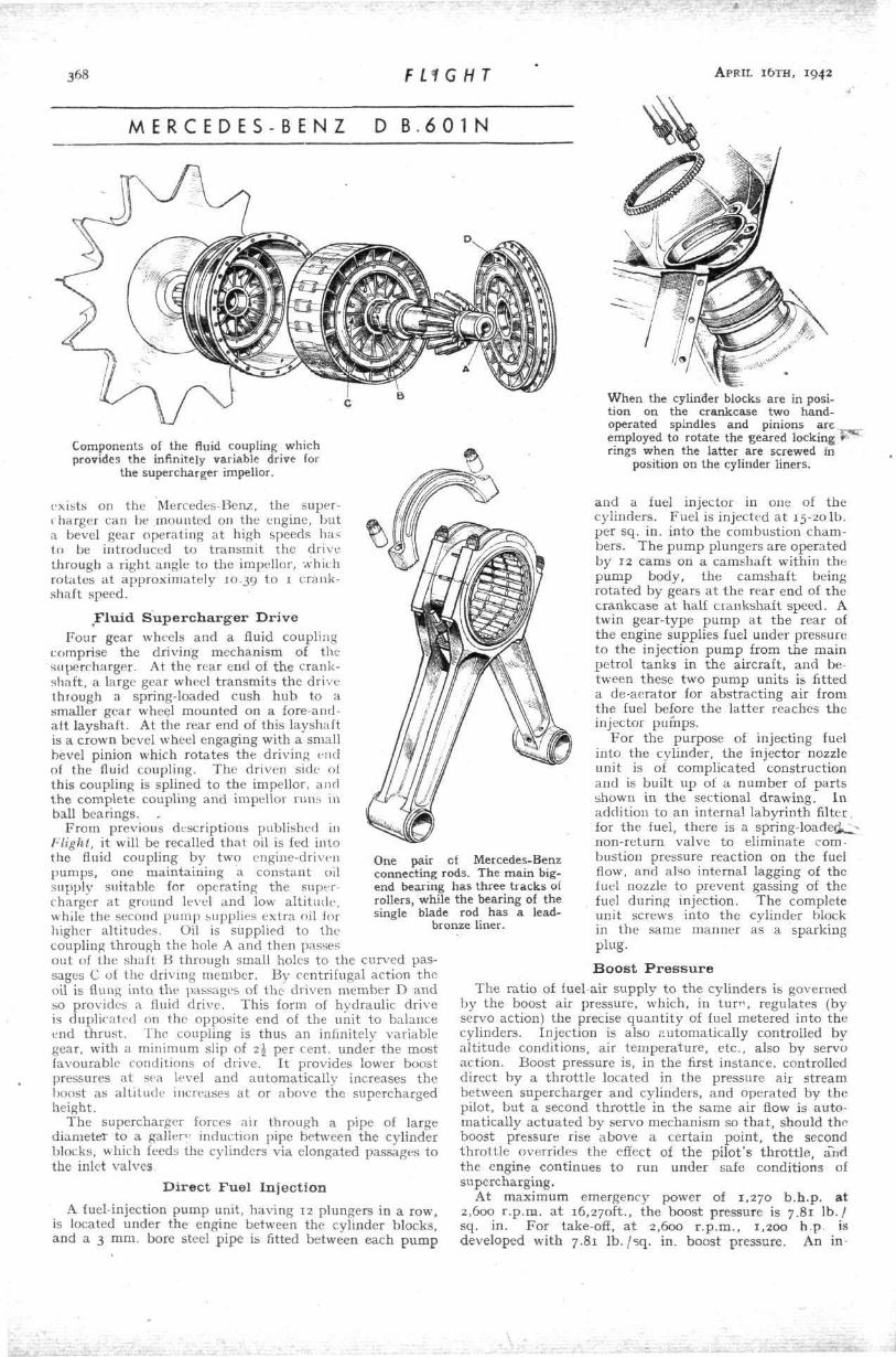
Components of the supercharger, including the impellor and unit carrying
diffuser vanes.
(Left) A section of the D.B.601N cylinder block sawn through to show design of cylinder walls, coolant passages, valve ports and valves. (Above) The single camshaft on each cylinder block operates two inlet and two exhaust valves per cylinder, shown reversed. Rollers are interposed between
cams and rockers.
the pinion on the crankshaft having 36 teeth engaging with 56 teeth on the airscrew shaft gear wheel (1.55 to 1 ratio). Another type has a ratio of 1.88 to 1. A feature of the D.B.601 and other German aircraft engines is tha t the airscrew and its h u b are a t tached direct to the reduction-gear shaft by a serrated face-to-face joint, and not in the normal manner by an horizontally splined coupling between the hub-and airscrew shaft.
T w o C a m s f o r F o u r V a l v e s
Two inlet and two exhaust valves are fitted to .each cylinder in inserted valve seats—both inlet and exhaust valves being stellited—while the exhaust valves are sodium
cooled. The valves are operated through short rockers, and ball joints are interposed between rocker and valve stem. One cam successively operates an inlet and exhaus t valve per revolution through the ar rangement of rockers, t h u s two cams only, are required for the four valves. Two sparking plugs per cylinder are located on- the outer side of the engine, and their firing points are directly opposite t o the fuel-injection nozzle in the combustion chamber .
Being inverted, the Mercedes-Benz engine has no sump, and oil draining from the crankshaft and connecting rods gravi tates through fore-and-aft drain pipes to the lowest point in the crankshaft casings (rear end), where scavenge pumps driven from the
camshaft pass the oil back to the oil t anks .
Since clear fore-and-aft space is required for the mount ing of a cannon a t the rear of the crankcase, the supercharger has necessarily had to be mounted with its impellor axes transverse to the centre line of the engine to place the bulk of the supercharger volute casing on one side, and no t in the positions found in the Merlin X X , Allison? or other " i n l i ne" engines. As no carburet tor

THE INVERTED* V TWELVE CYLINDER^ D.B.601N GUN INTERRUPTER
GEAR
TWIN MAGNETO & DISTRIBUTOR
GENERATOR
MOUNTING FOR ELECTRiCOR.
SUPERCHARGER IMPEUOR
Germany's Leading In-line Engine RUBBER ENGINE
MOUNTING OILER BEARING ^NNECTTNG ROD
CYLINDER BUJLK _ GEARED LOCKING
|jfc IL_/ RING
SUPERCHARGER FLUID COUPUNG
DRIVE
AUTOMATICALLY OPERATED THROTTLE
CAMSHAFT MAIN
OIL INTAKE
OIL ' FILTER
^ TWIN PETROL PUMPS FEEDING INJECTION PUMPS
SERVO OIL PUMPS FEEDING
SUPERCHARGER s FLUID COUPUNG '
j , SCAVENGE OIL PUMP (IN EACH CAMSHAFT CASE)
FUEL -„ •„ FUEL INJECTOR
rr J2s£k~, INJECTOR DE -AERATOR,. RPE 12 PLUNGER (ONE FOR EACH
FUEL INJECTION CYUNDER) PUMP UNIT / -~f
LOCATED BETWEEN / / CYUNDER BANKS '
2. INLET & 2 EXHAUST VALVES PER CYUNDER
06s Part-sect ional drawing of the liquid-cooled D.B.601N of 33.9 l i tres, bore and stroke 150 x 160 m m F««t,„.«, „* ** engine are the twelve plunger in-line direct injection pump , and the fluid coupling which provides an infmitelv v S ! « . r i
the supercharger drive. B.H.P. at 2,600 r .p .m. is 1,270, which for a weight of 1540 m 1 2 0 I n ' h ^ g
>
CM
H H
I
a:
Lu
3 68 FLIGHT A P R I L I 6 T H , 1942
M E R C E D E S - B E N Z D B . 6 0 1 N
Components of the fluid coupling which provides the infinitely variable drive for
the supercharger impellor.
exists on the Mercedes-Benz, the super-< harger can be mounted on the engine, but a bevel gear operating a t high speeds has to be introduced to t ransmit the drive through a right angle to the impellor, which rotates a t approximately 10.39 to 1 crankshaft speed.
F l u i d S u p e r c h a r g e r D r i v e
Four gear wheels and a fluid coupling comprise the driving mechanism of the supercharger. At the rear end of the crankshaft, a large gear wheel t ransmits the drive through a spring-loaded cush h u b to a smaller gear wheel mounted on a fore-and-aft layshaft. At the rear end of this layshaft is a crown bevel wheel engaging with a small bevel pinion which rotates the driving end of the fluid coupling. The driven side of this coupling is splined to the impellor, and the complete coupling and impellor runs in ball bearings.
From previous descriptions published in Flight, it will be recalled tha t oil is fed into the fluid coupling b y two engine-driven pumps, one maintaining a constant oil supply suitable for operating the supercharger a t ground level and low al t i tude, while the second p u m p supplies extra oil for higher al t i tudes. Oil is supplied to the coupling through the hole A and then passes out of the shaft B through small holes to the curved passages C of the driving member. By centrifugal action the oil is flung into the passages of the driven member D and so provides a fluid drive. This form of hydraulic drive is duplicated on the opposite end of the unit to balance end thrus t . The coupling is thus an infinitely variable gear, with a minimum slip of i\ per cent, under the most favourable conditions of drive. I t provides lower boost pressures a t sea level and automatical ly increases the boost as al t i tude increases a t or above the supercharged height.
The supercharger forces air through a pipe of large diameter to a galler" induction pipe between the cylinder blocks, which feeds the cylinders via elongated passages to the inlet valves.
D i r e c t F u e l I n j e c t i o n
A fuel-injection pump unit, having 12 plungers in a row, is located under the engine between the cylinder blocks, and a 3 mm. bore steel pipe is fitted between each p u m p
One pair cf Mercedes-Benz connecting rods. The main big-end bearing has three tracks of rollers, while the bearing of the single blade rod has a lead-
bronze liner.
When the cylinder blocks are in position on the crankcase two hand-operated spindles and pinions are. „ employed to rotate the geared locking ^— rings when the latter are screwed In
position on the cylinder liners.
and a fuel injector in one of the cylinders. Fuel is injected a t 15-20 lb . per sq. in. into the combustion chambers. The p u m p plungers are operated by 12 cams on a camshaft within the p u m p body, the camshaft being ro ta ted by gears a t the rear end of the crankcase a t half crankshaft speed. A twin gear-type p u m p a t the rear of the engine supplies fuel under pressure to the injection p u m p from the main petrol tanks in the aircraft, and between these two p u m p units is fitted a de-aerator for abstract ing air from the fuel before the la t ter reaches the injector pumps .
Fo r the purpose of injecting fuel into the cylinder, the injector nozzle uni t is of complicated construction and is built up of a number of par ts shown in t h e sectional drawing. In addit ion to an internal labyr inth filter. for the fuel, there is a spr ing- loaded,^ non-return valve to eliminate combustion pressure reaction on the fuel flow, and also internal lagging of the fuel nozzle to prevent gassing of the fuel during injection. The complete uni t screws into the cylinder block in the same manner as a sparking plug.
B o o s t P r e s s u r e
The rat io of fuel-air supply to the cylinders is governed by the boost air pressure, which, in turn , regulates (by servo action) the precise quan t i ty of fuel metered into the cylinders. Injection is also automatical ly controlled by al t i tude conditions, air t empera ture , etc. , also by servo action. Boost pressure is, in the first instance, controlled direct by a throt t le located in the pressure air s t ream between supercharger and cylinders, and operated by the pilot, bu t a second thro t t le in the same air flow is automatically ac tuated by servo mechanism so t h a t , should the boost pressure rise above a certain point, t he second thro t t le overrides the effect of the pilot 's th ro t t le , and the engine continues to run under safe conditions of supercharging.
At max imum emergency power of 1,270 b .h .p . a t 2,600 r .p .m. a t 16,270ft., the boost pressure is 7.81 l b . / sq. in. For take-off, a t 2,600 r .p .m. , 1,200 h .p is developed with 7.81 l b . / s q . in. boost pressure. An in-

A P R I L I 6 T H , 1942 FLIGHT 369
MERCEDES-BENZ D.B.601 N
(Left) The cylinder block is secured to the crankcase by a geared locking ring on each cylinder
liner. (Below) Section of the fuel injector fitted to each cylinder. A 3 mm. bore pipe feeds fuel into the labyrinth filter, from whence the fuel passes a nonreturn valve to the nozz le p rov ided with six small jets. The lagging is employed to prevent vaporization of the fuel by local heat.
LAGGING
GEARED LOCKING
RING LABYRINTH
FILTER
genious mechanism allows for increased boost and power for take-off for the duratioruof one minute . When opening up, t h e pilot gives an increased movement t o his thro t t le lever, which also operates a clockwork gear in the control mechanism. This clockwork device keeps the throt t le a t its extra opening unti l a small sl ipstream-operated windmill re tards the opening a t the end of a minu te , and the engine then returns to its normal full-throttle power. There is also another mechanism on the engine, interconnected with the throt t le and the oil-pressure system, by which the spark plugs are cleaned by t empora ry advancement of the ignition when the engine has been s tar ted u p from cold
,.^p\Jjen the plugs tend to oil up) , re tardat ion of ignition to normal being restored shortly afterwards.
E n g i n e A u x i l i a r i e s
At the rear of the engine, and driven by gears from the crankshaft , are the gun-interrupter mechanisms (for Me log), Bosch dual magneto, and electric generator. Electric or hand star ters can be bolted to the casing a t the rear end of the crankcase below the magneto and driven direct through a dog coupling to the crankshaft . Below the cannon mount ing are located the throt t le mechanism and main oil filter and fuel pumps , and all external fuel and oil pipes are wire wound and flexible, with banjo connection fittings. The twin delivery centrifugal coolant pump and main oil-pressure pumps are located between the cylinder blocks and in front of the main oil filter.
Net d ry weight is 1,400 lb . , but with all accessories, coolant header t ank , piping and airscrew control gear, etc. ,
(Above) The Bosch twelve - plunger injection pump and a few of its parts. The camshaft with twelve cams for operating the plungers is
of special interest.
t he weight is 1,540 lb . Thus, a t 1,270 maxim u m b .h .p . at 2,600 r .p .m. , a figure of 1.20 l b . / h . p . is obtained.
A feature of German design is quick inter-changeabili ty. The D . B . engine designed for rapid de tachment and replacement in the aircraft is complete with auxiliaries. I t has electron cantilever bearers of s turdy section
supported by four rubber-metal reinforced mount ings—two high up a t the forward end of the crankcase and two a t a lower position a t the rear.
G a r b u r a t i o n F e a t u r e s In comparing t h e major features of t h e Merlin, Allison
and Daimler-Benz, it is interesting to note t h a t t h e three engines have entirely different systems of introducing air and fuel into the cylinders. Whereas carburet tors of normal design are fitted to the Merlin, and air-fuel mixture passes as a homogeneous stream through the supercharger, t he Allison has a triple ventur i carbure t tor which passes air only t o a point in the supercharger intake elbow where i t meets a metered flow of fuel issuing from a single jet and supplied under pressure from the fuel p u m p in t h e engine, the jet supplying fuel for the 12 cylinders. In t h e case of the D . B . , air only is conveyed direct t o the combustion chambers , where i t meets the fuel sprayed from the injector nozzles just before the ignition point . A short curved intake on the port side of the engine cowling conducts air through a wire mesh grid to the supercharger impellor.
V.D.M. propellers are used, the motor with its pitch-limit control and filter uni t being carried on a bracket supported by the engine crankcase. As the controlling energy is separate from the engine, the airscrew can be feathered with "the engine stopped. The blades are interchangeable, and a blade can be removed for inspection and replaced in about 20 minutes . The tota l weight of t h e airscrew is 304 lb . , including the motor bracket and wiring.
LIQUID-COOLED IN-LINE ENGINES
. ;""
Merlin XX
Allison C.15
Mercedes-Benz D.B.601 N
Bore
Inches
5.4
5.5
5.9
Stroke
Inches
6.0
6.0
6.29
Capacity
Litres
27.0
28.1
33.9
Comp. Ratio
-6 : 1
6.66 : 1
7.9 :1
Horse-power
1,175 at 2.850 r.p.m. at 17,500ft.
1,240 at 2,850 r.p.m. at 10,000ft.
1,090 at 3,000 r.p.m. at ' 13.200ft.
1,270 at 2,600 r.p.m. at 16.2:50ft.
Weight
Lb.
1.450
1.340
1.540
Lb. per h.p.
1.13
1.23
1.20
Companion articles in this series of descriptions of prominent aircraft engines of the war appeared in the following issues :—
BRISTOL HERCULES— November 27th, 1941.
ROLLS-ROYCE MERLIN XX-February 26th, 1942.
ALLISON—March 26th, 1942.