april 2009 - interwest · castel products can be supplied with different connections. in particular...
TRANSCRIPT


2
April 2009
3
Expansion • thermostatic expansion valves with interchangeable orifice assembly 16valves • PWM solenoid expansion valves with interchangeable orifice 26
Solenoid • valves for refrigerating systems 32valves • coils 40
• permanent magnet 43• connectors 44• valves for different fluids 44
Safety devices • safety valves 3030 50• safety valves 3060 57• ball shut-off valves 59• changeover devices 60• unions 62• fusible plugs 63
Check valves 65
Water regulating valves 71
Liquid indicatorsMoisture – liquid indicators 77
Dehydrators • dehydration of refrigerants 83• anti-acid solid core filter driers 85• solid core filter driers with sight glass 94• solid core bi-flow filter driers 97• filter driers with replaceable anti-acid solid core 100• mechanical filters with replaceable filtering block 105• strainers 110
Oi105
Valves • hermetic valves 112• receiver valves 114• stop valves 116• diaphragm valves 118• rotalock valves 120• capped valves 122• globe valves 124• ball valves 126• gauge mounting valves 129• line piercing valve 130
Threaded brass fittings 131
Solder copper fittings 141
Access fittings 153
Spare parts 159
Index

4
The techical data in this handbook are indicative. Castel reserves theright to modify the same at any time without any previous notice.
The products listed in this handbook are protected according to the law

5
From quality our naturaldevelopment
After more than forty years in the industry of Refrigeration and
Air Conditioning components, Castel Quality Range of Products
is well known and highly appreciated all over the world.
Quality is the main issue of our Company and it has a special
priority, in every step, all along the production cycle.
We produce on high tech machinery and updated automatic
production lines, operating in conformity with the safety and
environment standards currently enforced.
Castel offers to the Market and to Manufacturers fully tested
products suitable with HCFC and HFC Refrigerants currently
used in the Refrigeration & Air Conditioning Industry.
UNI EN ISO 9001:2008 issued by ICIM certifies the Quality System
of the Factory.
Moreover Castel Products count a number of certifications in
conformity with the EEC Directives and with European and
American Quality Approvals.
6
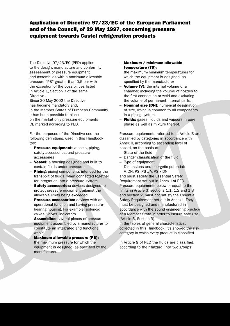
Application of Directive 97/23/EC of the European Parliamentand of the Council, of 29 May 1997, concerning pressureequipment towards Castel refrigeration products
– Maximum / minimum allowabletemperature (TS):the maximum/minimum temperatures forwhich the equipment is designed, asspecified by the manufacturer
– Volume (V): the internal volume of achamber, including the volume of nozzles tothe first connection or weld and excludingthe volume of permanent internal parts.
– Nominal size (DN): numerical designationof size, which is common to all componentsin a piping system.
– Fluids: gases, liquids and vapours in purephase as well as mixture thereof.
Pressure equipments referred to in Article 3 areclassified by categories in accordance withAnnex II, according to ascending level ofhazard, on the basis of: – State of the fluid– Danger classification of the fluid– Type of equipment– Dimensions and energetic potential:
V, DN, PS, PS x V, PS x DNand must satisfy the Essential SafetyRequirement set out in Annex I of PED.Pressure equipments below or equal to thelimits in Article 3, sections 1.1, 1.2 and 1.3and section 2, must not satisfy the EssentialSafety Requirement set out in Annex I. Theymust be designed and manufactured inaccordance with the sound engineering practiceof a Member State in order to ensure safe use(Article 3, Section 3).In the tables of general characteristics,collected in this Handbook, it’s showed the riskcategory in which every product is classified.
In Article 9 of PED the fluids are classified,according to their hazard, into two groups:
The Directive 97/23/EC (PED) applies to the design, manufacture and conformityassessment of pressure equipment and assemblies with a maximum allowablepressure “PS” greater than 0,5 bar with the exception of the possibilities listed in Article 1, Section 3 of the same Directive.Since 30 May 2002 the Directive has become mandatory and,in the Member States of European Community,it has been possible to place on the market only pressure equipments CE marked according to PED.
For the purposes of the Directive see thefollowing definitions, used in this Handbooktoo:– Pressure equipment: vessels, piping,
safety accessories, and pressureaccessories
– Vessel: a housing designed and built tocontain fluids under pressure.
– Piping: piping components intended for thetransport of fluids, when connected togetherfor integration into a pressure system.
– Safety accessories: devices designed toprotect pressure equipment against theallowable limits being exceeded.
– Pressure accessories: devices with anoperational function and having pressure-bearing housing. For example: solenoidvalves, valves, indicators.
– Assemblies: several pieces of pressureequipment assembled by a manufacturer toconstitute an integrated and functionalwhole.
– Maximum allowable pressure (PS):the maximum pressure for which theequipment is designed, as specified by themanufacturer.
7
– Group I comprises dangerous fluids. Adangerous fluid is a substance orpreparation covered by the definitions inArticle 2 of Council Directive 67/548/EECof 27 June 1967 and followingamendments, relating to the classification,packaging and labeling of dangeroussubstance. Group I comprises fluids definedas: explosive, extremely flammable, highlyflammable, flammable, very toxic, toxic,oxidizing.
– Group II comprises all the others fluids notreferred to in group I.
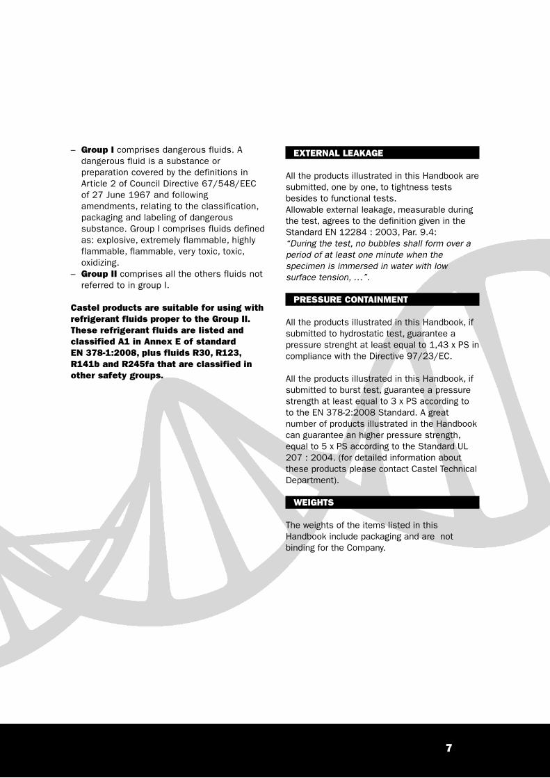
Castel products are suitable for using withrefrigerant fluids proper to the Group II.These refrigerant fluids are listed andclassified A1 in Annex E of standard EN 378-1:2008, plus fluids R30, R123,R141b and R245fa that are classified inother safety groups.
EXTERNAL LEAKAGE
All the products illustrated in this Handbook aresubmitted, one by one, to tightness testsbesides to functional tests.Allowable external leakage, measurable duringthe test, agrees to the definition given in theStandard EN 12284 : 2003, Par. 9.4:“During the test, no bubbles shall form over aperiod of at least one minute when thespecimen is immersed in water with lowsurface tension, …”.
PRESSURE CONTAINMENT
All the products illustrated in this Handbook, ifsubmitted to hydrostatic test, guarantee apressure strenght at least equal to 1,43 x PS incompliance with the Directive 97/23/EC.
All the products illustrated in this Handbook, ifsubmitted to burst test, guarantee a pressurestrength at least equal to 3 x PS according toto the EN 378-2:2008 Standard. A greatnumber of products illustrated in the Handbookcan guarantee an higher pressure strength,equal to 5 x PS according to the Standard UL207 : 2004. (for detailed information aboutthese products please contact Castel TechnicalDepartment).
WEIGHTS
The weights of the items listed in thisHandbook include packaging and are notbinding for the Company.

Application of Directive 2002/95/EC of the European Parliament andof the Council, of 27 January 2003, on the restriction of the use ofcertain hazardous substances in electrical and electronic equipment
listed in the Annex of the same Directive;among these applications the followingexceptions are particularly interesting in airconditioning / refrigerating systems:
– Lead as an alloying element in steelcontaining up to 0,35% lead by weight,aluminium containing up to 0,4% lead byweight and as a copper alloy containing up to4% lead by weight
– Hexavalent chromium as an anti-corrosion ofthe carbon steel cooling system in absorptionrefrigerators
The Member States of European Community hadto adopt the two Directives 2002/95/EC and2002/96/EC, with the next updating2003/108/EC, before 13 August 2004, unlessdelays granted by the European Parliament.For a long time Castel Company has started acareful inquiry, together with its suppliers, toidentify the presence or not of the above-mentioned hazardous substances, either in itsown products or in its own production processes,and to remove them progressively.At the end of this wide examination CastelCompany may declare that its products:1. Do not contain mercury, cadmium,
polybrominated biphenyls (PBB),polybrominated diphenyl ethers (PBDE)
2. Do not contain hexavalent chromium, used forthe surface treatments (yellow zinc plating) ofsteel parts. Castel Company has removed theyellow zinc plating treatments from all itsproducts, before the end of 2005, and haschosen:– other surface treatments containing trivalent
chromium instead of hexavalent chromium.– where possible, other materials which don’t
need surface treatments.3. Contain lead as an alloying element in steel,
aluminium and copper alloys within theaccepted limits according to the Annex ofRoHS Directive.
The purpose of Directive 2002/95/EC (RoHSDirective) is to prevent or restrict the use ofhazardous substances in electrical andelectronic equipment and to contribute to theenvironmentally sound recovery and disposal ofwaste electrical and electronic equipment.RoHS Directive shall apply to electrical andelectronic equipment falling under the categories1, 2, 3, 4, 5, 6, 7 and 10 set out in Annex 1A toDirective 2002/96/EC (WEEE – Waste electricaland electronic equipment) and to electric lightbulbs and luminaries in households.The equipment proper to the first category,“Large household appliances”, and to the10th category, “Automatic dispensers”, ofAnnex 1A in WEEE Directive, are specified inAnnex 1B in the same Directive; this list ofproducts shows:– Large cooling appliance– Refrigerators– Freezers– Other large appliances used for refrigeration,
conservation and storage of food– Air conditioner appliances– Other fanning, exhaust ventilation and
conditioning equipment– Automatic dispenser for hot or cold bottles
and cans
Article 10 of WEEE Directive establishes that,from 13 August 2005, new electrical andelectronic equipment put on the market areappropriately identified as waste subject toseparate collection, by means of the propersymbol shown in Annex IV of the same Directive.
Article 4 of RoHS Directive establishes that, from1 July 2006, new electrical and electronicequipment put on the market does not containthe following substances:– Lead– Mercury– Cadmium– Hexavalent chromium– Polybrominated biphenyls (PBB)– Polybrominated diphenyl ethers (PBDE)
The restriction of use of these hazardoussubstances shall not apply to the applications
8

CONNECTIONS OF CASTEL PRODUCTS
Castel products can be supplied with differentconnections.
In particular Castel products are producedeither with threaded connections or solderconnections.Table 1 shows the equivalence between Castelcodes and dimensions in inches. These codesare commonly used in the international market.Table 2 shows the equivalence between Castelcodes and dimensions in millimeters.
CASTELcode
Dimension[in]
TABLE 1 - Equivalence between Castel code and dimension in inches
CASTELcode
Dimension[mm]
. …/M6
. …/M10
. …/M12
. …/M15
. …/M18
. …/M22
. …/M28
. …/M42
. …/M64
. …/M80
6
10
12
15
18
22
28
42
64
80
TABLE 2: Equivalence between Castel code and dimension in millimeters
1/8"
1/4"
3/8"
1/2"
5/8"
3/4"
7/8"
1"
1" 1/8
1" 3/8
1" 5/8
2" 1/8
2" 5/8
3"
3" 1/8
3" 1/2
3" 5/8
4" 1/8
4" 1/4
. …/1
. …/2
. …/3
. …/4
. …/5
. …/6
. …/7
. …/8
. …/9
. …/11
. …/13
. …/17
. …/21
. …/24
. …/25
. …/28
. …/29
. …/33
. …/34
F.e. 1098/7 – solenoid valve with solder connection
with Ø = 7/8”
F.e. 4411/M42A – filter drier with replaceable anti-acid
solid core with solder connection with Ø = 42 mm.
9
10
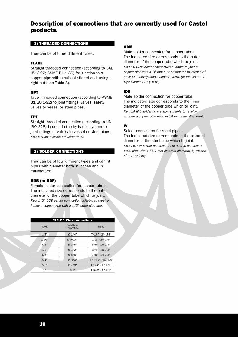
1) THREADED CONNECTIONS
They can be of three different types:
FLAREStraight threaded connection (according to SAEJ513-92; ASME B1.1-89) for junction to acopper pipe with a suitable flared end, using aright nut (see Table 3).
NPTTaper threaded connection (according to ASMEB1.20.1-92) to joint fittings, valves, safetyvalves to vessel or steel pipes.
FPTStraight threaded connection (according to UNIISO 228/1) used in the hydraulic system tojoint fittings or valves to vessel or steel pipes.F.e.: solenoid valves for water or air.
2) SOLDER CONNECTIONS
They can be of four different types and can fitpipes with diameter both in inches and inmillimeters:
ODS (or ODF)Female solder connection for copper tubes. The indicated size corresponds to the outerdiameter of the copper tube which to joint.F.e.: 1/2" ODS solder connection suitable to receive
inside a copper pipe with a 1/2" outer diameter.
ODMMale solder connection for copper tubes. The indicated size corresponds to the outerdiameter of the copper tube which to joint.F.e.: 16 ODM solder connection suitable to joint a
copper pipe with a 16 mm outer diameter, by means of
an M16 female/female copper sleeve (in this case the
type Castel 7700/M16).
IDSMale solder connection for copper tube. The indicated size corresponds to the innerdiameter of the copper tube which to joint.F.e.: 10 IDS solder connection suitable to receive
outside a copper pipe with an 10 mm inner diameter).
WSolder connection for steel pipes. The indicated size corresponds to the externaldiameter of the steel pipe which to joint.F.e.: 76,1 W solder connection suitable to connect a
steel pipe with a 76,1 mm external diameter, by means
of butt welding.
FLARE Suitable forCopper tube thread
1/4"
5/16"
3/8"
1/2"
5/8"
3/4"
7/8"
1"
Ø 1/4"
Ø 5/16"
Ø 3/8"
Ø 1/2"
Ø 5/8"
Ø 3/4"
Ø 7/8"
Ø 1"
7/16" - 20 UNF
1/2" - 20 UNF
5/8" - 18 UNF
3/4" - 16 UNF
7/8" - 14 UNF
1.1/16" - 14 UNS
1.1/4" - 12 UNF
1.3/8" - 12 UNF
TABLE 3: Flare connections
Description of connections that are currently used for Castelproducts.

11
THE Kv FACTOR
«Table 1» shows refrigeration capacity valueswith unit Kv related to the nominal workingconditions specified in «Table 2».
Appropriate corrective coefficients may becalculated taking the values shown from Table3 to Table 8 as a basis; this will make itpossible to predict actual working conditions.
As a result:
– Liquid line:Q = Kv · Q1 · L1 · L2
– Suction lineQ = Kv · Q1 · S1 · S2
– Hot gas lineQ = Kv · Q1 · H1 · H2
since:
Q = required refrigeration capacity [kW];Kv = characteristic valve coefficient [m3/h];Q1 = reference refrigeration capacity [kW]
(Table 1).
L1 S1 H1 = are correction factors of therefrigeration capacity in the presence ofoperating temperatures different from referenceconditions.
L2 S2 H2 = are correction factors of therefrigeration capacity for pressure dropsdifferent from reference conditions.
The correct sizing of tubes and components ofa refrigerating system is of the utmostimportance for all kinds of plants; oversizingand undersizing are both to be avoided sincethey are equally hazardous for the correctoperation of the system.
The correct selection of a component is basedon the knowledge of the relationship betweencapacity and pressure drop through thatcomponent. For this purpose, EN 60534-1,EN 60534-2-1 and EN 60534-2-3 standardsrequire manufacturers to specify the Kvcoefficient for every product.
The Kv factor is defined as the cold waterflow (volumic mass r = 1000 kg/m3) inm3/h resulting in a 1 bar pressure dropwith a completely open valve.
This definition applies to all products describedin this handbook.
The merely physical meaning, this coefficientprecisely defines the fluid-dynamic andconstruction characteristics of the product, sothat, with the addition of other parametersmore closely related to the nature andconditions of the fluid under consideration, thecapacity/pressure drop ratio may be preciselydetermined.
Castel provides appropriate tables for the mostcommonly used refrigerants in typical plantworking conditions in order to help engineers inthe correct selection of its products.
TABLE 1
KvFactor[m3/h]
R134a
Liquid Vapour Hot Gas
Refrigeration Capacity [kW]
1 16,85
R22
18,00
R404A
11,90
R407C
18,74
R410A
19,04
R507
11,80
R134a
2,16
R22
2,70
R404A
2,26
R407C
2,68
R410A
3,60
R507
2,15
R134a
8,50
R22
11,70
R404A
10,00
R407C
11,62
R410A
13,00
R507
7,77
+4
TABLE 2 - Nominal Working Conditions
–
+18
+38
0,15
1
Application Suction Temperature[°C]
Condensing Temperature[°C]
Pressure drop [bar]
LIQUID
VAPOUR
HOT
GAS
Evaporating Temperature[°C]

12
Liquid lineTABLE 3 - Correction Factors – L1 of the refrigeration capacity for operating temperatures different from nominal values
LiquidTemperature
[°C] Refrigerant+ 10 + 5 0 – 5 – 10 – 15 – 20 – 25 – 30 – 35 – 40
Evaporating Temperature [°C]
0
+10
+20
+30
+40
+50
+60
R134a
R22
R404A
R407C
R410A
R507
R134a
R22
R404A
R407C
R410A
R507
R134a
R22
R404A
R407C
R410A
R507
R134a
R22
R404A
R407C
R410A
R507
R134a
R22
R404A
R407C
R410A
R507
R134a
R22
R404A
R407C
R410A
R507
R134a
R22
R404A
R407C
R410A
R507
1,23
1,19
1,28
1,23
1,19
1,33
1,12
1,08
1,13
1,12
1,08
1,17
1,00
0,99
0,99
0,99
1,00
1,00
0,88
0,89
0,85
0,85
0,85
0,80
0,76
0,79
0,68
0,71
0,70
0,58
1,21
1,17
1,26
1,22
1,17
1,30
1,10
1,07
1,12
1,10
1,07
1,15
0,98
0,98
0,97
0,97
0,99
0,97
0,86
0,88
0,83
0,84
0,84
0,78
0,74
0,78
0,66
0,70
0,69
0,56
1,19
1,16
1,25
1,20
1,16
1,28
1,08
1,06
1,09
1,08
1,06
1,13
0,96
0,97
0,95
0,96
0,96
0,95
0,84
0,87
0,81
0,82
0,81
0,76
0,72
0,77
0,64
0,68
0,67
0,54
1,17
1,16
1,22
1,18
1,16
1,26
1,06
1,05
1,07
1,06
1,05
1,10
0,94
0,96
0,93
0,94
0,95
0,93
0,82
0,86
0,79
0,80
0,80
0,74
0,70
0,76
0,62
0,66
0,66
0,52
1,15
1,15
1,20
1,16
1,15
1,23
1,04
1,04
1,05
1,04
1,04
1,08
0,92
0,95
0,92
0,92
0,94
0,90
0,80
0,85
0,77
0,79
0,79
0,71
0,68
0,75
0,60
0,65
0,65
0,50
1,13
1,13
1,17
1,15
1,13
1,20
1,02
1,03
1,04
1,03
1,03
1,05
0,90
0,93
0,89
0,90
0,93
0,87
0,78
0,84
0,75
0,77
0,78
0,68
0,66
0,74
0,58
0,63
0,63
0,47
1,34
1,32
1,40
1,35
1,32
1,52
1,23
1,22
1,27
1,23
1,22
1,35
1,11
1,11
1,16
1,13
1,11
1,17
1,00
1,02
1,02
1,00
1,02
1,02
0,88
0,92
0,87
0,89
0,92
0,85
0,76
0,82
0,73
0,75
0,76
0,66
0,64
0,72
0,56
0,61
0,61
0,45
1,32
1,31
1,38
1,33
1,31
1,49
1,21
1,21
1,25
1,21
1,21
1,32
1,09
1,10
1,13
1,11
1,10
1,14
0,98
1,01
0,99
0,99
1,01
0,99
0,86
0,90
0,85
0,87
0,91
0,82
0,74
0,81
0,71
0,73
0,74
0,63
0,62
0,71
0,54
0,60
0,60
0,42
1,30
1,29
1,36
1,31
1,29
1,46
1,18
1,19
1,23
1,19
1,19
1,29
1,07
1,08
1,11
1,09
1,08
1,12
0,96
0,99
0,97
0,97
0,99
0,96
0,84
0,89
0,83
0,85
0,90
0,79
0,72
0,80
0,69
0,72
0,73
0,60
0,60
0,70
0,52
0,58
0,58
0,40
1,28
1,27
1,33
1,29
1,27
1,42
1,16
1,17
1,20
1,18
1,18
1,26
1,05
1,07
1,08
1,07
1,07
1,08
0,94
0,98
0,95
0,95
0,98
0,93
0,82
0,87
0,80
0,83
0,87
0,76
0,70
0,78
0,67
0,70
0,72
0,57
0,58
0,68
0,50
0,56
0,57
0,36
1,26
1,25
1,31
1,25
1,25
1,38
1,14
1,16
1,18
1,16
1,16
1,22
1,03
1,05
1,06
1,06
1,05
1,04
0,91
0,96
0,93
0,94
0,96
0,89
0,80
0,86
0,78
0,82
0,86
0,72
0,68
0,77
0,65
0,69
0,71
0,54
0,56
0,67
0,48
0,55
0,56
0,33
TABLE 4 - Correction Factors – L2 of the refrigeration capacity for pressure drops different from nominal values
Pressuredrop[bar]
0,01 0,03 0,05 0,10
L2 0,263 0,456 0,59 0,81 1,00 1,15 1,30 1,40 1,54 1,64 1,72 1,82 1,92 2,00
0,15 0,20 0,25 0,30 0,35 0,40 0,45 0,50 0,55 0,60
13
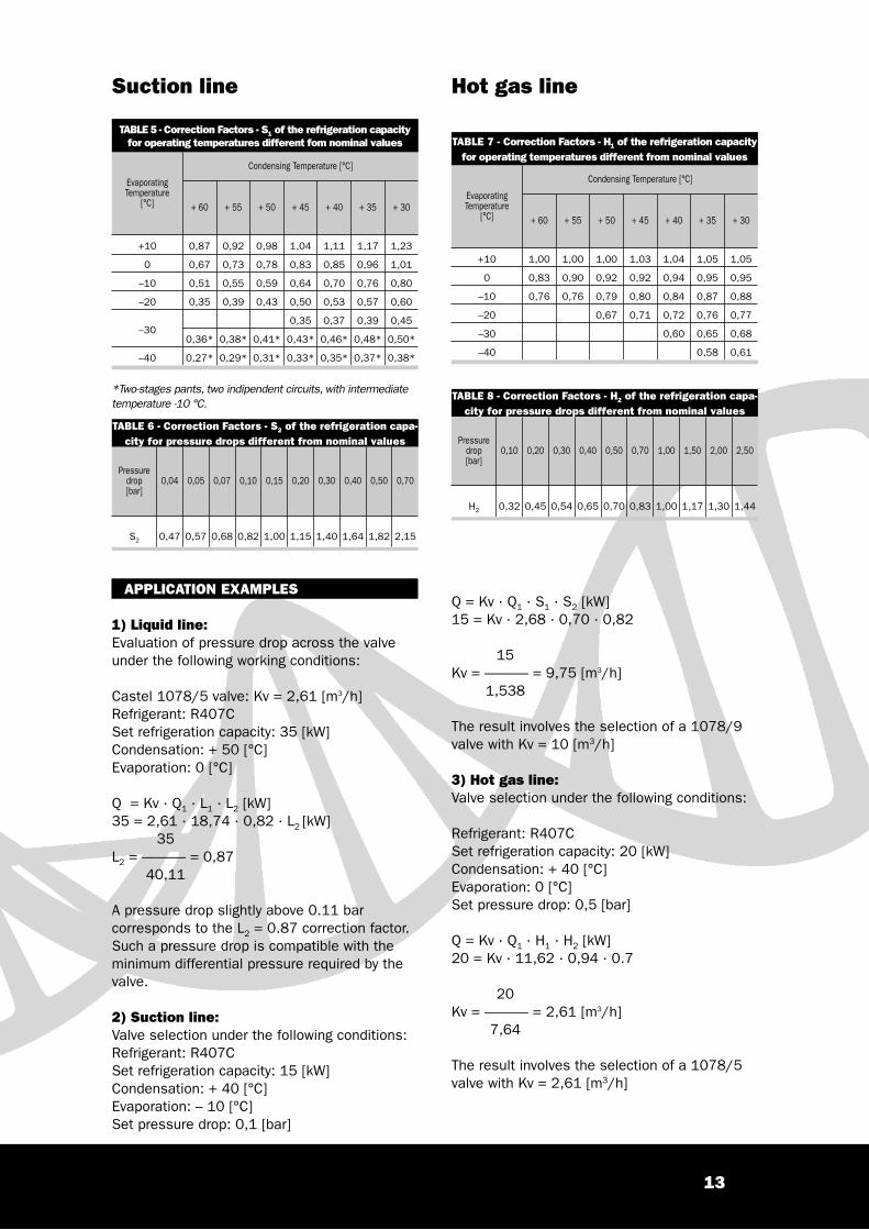
Suction line Hot gas line
Q = Kv · Q1 · S1 · S2 [kW]15 = Kv · 2,68 · 0,70 · 0,82
15Kv = ——— = 9,75 [m3/h]
1,538
The result involves the selection of a 1078/9valve with Kv = 10 [m3/h]
3) Hot gas line:Valve selection under the following conditions:
Refrigerant: R407CSet refrigeration capacity: 20 [kW]Condensation: + 40 [°C]Evaporation: 0 [°C]Set pressure drop: 0,5 [bar]
Q = Kv · Q1 · H1 · H2 [kW]20 = Kv · 11,62 · 0,94 · 0.7
20Kv = ——— = 2,61 [m3/h]
7,64
The result involves the selection of a 1078/5valve with Kv = 2,61 [m3/h]
APPLICATION EXAMPLES
1) Liquid line:Evaluation of pressure drop across the valveunder the following working conditions:
Castel 1078/5 valve: Kv = 2,61 [m3/h]Refrigerant: R407CSet refrigeration capacity: 35 [kW]Condensation: + 50 [°C]Evaporation: 0 [°C]
Q = Kv · Q1 · L1 · L2 [kW]35 = 2,61 · 18,74 · 0,82 · L2 [kW]
35L2 = ——— = 0,87
40,11
A pressure drop slightly above 0.11 barcorresponds to the L2 = 0.87 correction factor.Such a pressure drop is compatible with theminimum differential pressure required by thevalve.
2) Suction line:Valve selection under the following conditions:Refrigerant: R407CSet refrigeration capacity: 15 [kW]Condensation: + 40 [°C]Evaporation: – 10 [°C]Set pressure drop: 0,1 [bar]
TABLE 5 - Correction Factors - S1 of the refrigeration capacityfor operating temperatures different fom nominal values
Evaporating Temperature
[°C] + 60 + 55 + 50 + 45 + 40 + 35 + 30
Condensing Temperature [°C]
+10
0
–10
–20
–30
–40
0,87
0,67
0,51
0,35
0,36*
0,27*
0,92
0,73
0,55
0,39
0,38*
0,29*
0,98
0,78
0,59
0,43
0,41*
0,31*
1,04
0,83
0,64
0,50
0,35
0,43*
0,33*
1,11
0,85
0,70
0,53
0,37
0,46*
0,35*
1,17
0,96
0,76
0,57
0,39
0,48*
0,37*
1,23
1,01
0,80
0,60
0,45
0,50*
0,38*
TABLE 6 - Correction Factors - S2 of the refrigeration capa-city for pressure drops different from nominal values
Pressure drop[bar]
0,04 0,05 0,07 0,10 0,15 0,20 0,30 0,40 0,50 0,70
S2 0,47 0,57 0,68 0,82 1,00 1,15 1,40 1,64 1,82 2,15
TABLE 8 - Correction Factors - H2 of the refrigeration capa-city for pressure drops different from nominal values
Pressuredrop[bar]
0,10 0,20 0,30 0,40 0,50 0,70 1,00 1,50 2,00 2,50
H2 0,32 0,45 0,54 0,65 0,70 0,83 1,00 1,17 1,30 1,44
TABLE 7 - Correction Factors - H1 of the refrigeration capacityfor operating temperatures different from nominal values
EvaporatingTemperature
[°C] + 60 + 55 + 50 + 45 + 40 + 35 + 30
Condensing Temperature [°C]
+10
0
–10
–20
–30
–40
1,00
0,83
0,76
1,00
0,90
0,76
1,00
0,92
0,79
0,67
1,03
0,92
0,80
0,71
1,04
0,94
0,84
0,72
0,60
1,05
0,95
0,87
0,76
0,65
0,58
1,05
0,95
0,88
0,77
0,68
0,61
*Two-stages pants, two indipendent circuits, with intermediatetemperature -10 °C.

14

Expansion valves
16
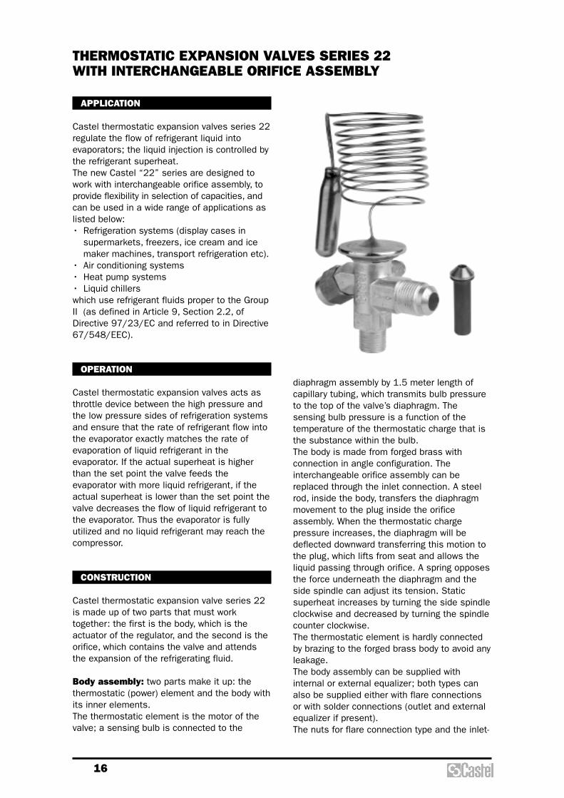
diaphragm assembly by 1.5 meter length ofcapillary tubing, which transmits bulb pressureto the top of the valve’s diaphragm. Thesensing bulb pressure is a function of thetemperature of the thermostatic charge that isthe substance within the bulb.The body is made from forged brass withconnection in angle configuration. Theinterchangeable orifice assembly can bereplaced through the inlet connection. A steelrod, inside the body, transfers the diaphragmmovement to the plug inside the orificeassembly. When the thermostatic chargepressure increases, the diaphragm will bedeflected downward transferring this motion tothe plug, which lifts from seat and allows theliquid passing through orifice. A spring opposesthe force underneath the diaphragm and theside spindle can adjust its tension. Staticsuperheat increases by turning the side spindleclockwise and decreased by turning the spindlecounter clockwise.The thermostatic element is hardly connectedby brazing to the forged brass body to avoid anyleakage.The body assembly can be supplied withinternal or external equalizer; both types canalso be supplied either with flare connectionsor with solder connections (outlet and externalequalizer if present). The nuts for flare connection type and the inlet-
APPLICATION
Castel thermostatic expansion valves series 22regulate the flow of refrigerant liquid intoevaporators; the liquid injection is controlled bythe refrigerant superheat.The new Castel “22” series are designed towork with interchangeable orifice assembly, toprovide flexibility in selection of capacities, andcan be used in a wide range of applications aslisted below:• Refrigeration systems (display cases in
supermarkets, freezers, ice cream and icemaker machines, transport refrigeration etc).
• Air conditioning systems• Heat pump systems• Liquid chillerswhich use refrigerant fluids proper to the GroupII (as defined in Article 9, Section 2.2, ofDirective 97/23/EC and referred to in Directive67/548/EEC).
OPERATION
Castel thermostatic expansion valves acts asthrottle device between the high pressure andthe low pressure sides of refrigeration systemsand ensure that the rate of refrigerant flow intothe evaporator exactly matches the rate ofevaporation of liquid refrigerant in theevaporator. If the actual superheat is higherthan the set point the valve feeds theevaporator with more liquid refrigerant, if theactual superheat is lower than the set point thevalve decreases the flow of liquid refrigerant tothe evaporator. Thus the evaporator is fullyutilized and no liquid refrigerant may reach thecompressor.
CONSTRUCTION
Castel thermostatic expansion valve series 22is made up of two parts that must worktogether: the first is the body, which is theactuator of the regulator, and the second is theorifice, which contains the valve and attendsthe expansion of the refrigerating fluid.
Body assembly: two parts make it up: thethermostatic (power) element and the body withits inner elements.The thermostatic element is the motor of thevalve; a sensing bulb is connected to the
THERMOSTATIC EXPANSION VALVES SERIES 22WITH INTERCHANGEABLE ORIFICE ASSEMBLY

17
TABLE 1a: General Characteristics of Body Assemblies of Liquid Charge Thermostatic Expansion Valves
externalequalizer
internalequalizer
Cataloguenumber
IN OUT Equal. OUT OUT Equal. min max
PS [bar]
SAE Flare ODS [mm] ODS [in]
Refri
gera
nt
Evap
orat
ing
Tem
pera
ture
Ran
ge[°C
]
Max
bul
bte
mpe
ratu
re [°
C]
MOP
TS [°C]Connections
–
2210/4E
2210/M12SE
2210/4SE
–
2220/4E
2220/M12SE
2220/4SE
–
2230/4E
2230/M12SE
2230/4SE
2210/4
2210/M12S
2210/4S
–
2220/4
2220/M12S
2220/4S
–
2230/4
2230/M12S
2230/4S
–
3/8"
1/2"
–
–
1/2"
–
–
1/2"
–
–
1/2"
–
–
1/2"
–
–
1/2"
–
–
–
–
–
1/4"
–
–
–
–
–
1/4"
–
–
–
–
–
1/4"
–
–
–
12
–
–
12
–
–
12
–
–
12
–
–
12
–
–
12
–
Equal.
–
–
–
–
6
–
–
–
–
–
6
–
–
–
–
–
6
–
–
–
1/2"
–
–
1/2"
–
–
1/2"
–
–
1/2"
–
–
1/2"
–
–
1/2"
–
–
–
–
–
1/4"
–
–
–
–
–
1/4"
–
–
–
–
–
1/4"
R22
R407C
R134a
R404A
R507
- 40 ›
+ 10
without 100
(1)-60 +120 34
RiskCategoryaccording
toPED
Art. 3.3
(1) When valve is installed. 60 °C with element not mounted
TABLE 1b: General Characteristics of Body Assemblies of MOP Charge Thermostatic Expansion Valves
externalequalizer
internalequalizer
Cataloguenumber
IN OUT Equal. OUT OUT Equal. min max
PS [bar]
SAE Flare ODS [mm] ODS [in]
Refri
gera
nt
Evap
orat
ing
tem
pera
ture
Rang
e [°C
]
Max
bul
b te
mpe
ratu
re [°
C]
MOP
TS [°C]Connections
–
2211/4E
2211/M12SE
2211/4SE
–
2221/4E
2221/M12SE
2221/4SE
–
2231/4E
2231/M12SE
2231/4SE
–
2234/4E
2234/M12SE
2234/4SE
2211/4
2211/M12S
2211/4S
–
2221/4
2221/M12S
2221/4S
–
2231/4
2231/M12S
2231/4S
–
2234/4
2234/M12S
2234/4S
–
3/8"
1/2"
–
–
1/2"
–
–
1/2"
–
–
1/2"
–
–
1/2"
–
–
1/2"
–
–
1/2"
–
–
1/2"
–
–
–
–
–
1/4"
–
–
–
–
–
1/4"
–
–
–
–
–
1/4"
–
–
–
–
–
1/4"
–
–
–
12
–
–
12
–
–
12
–
–
12
–
–
12
–
–
12
–
–
12
–
–
12
–
Equal.
–
–
–
–
6
–
–
–
–
–
6
–
–
–
–
–
6
–
–
–
–
–
6
–
–
–
1/2"
–
–
1/2"
–
–
1/2"
–
–
1/2"
–
–
1/2"
–
–
1/2"
–
–
1/2"
–
–
1/2"
–
–
–
–
–
1/4"
–
–
–
–
–
1/4"
–
–
–
–
–
1/4"
–
–
–
–
–
1/4"
R22
R407C
R134a
R404A
R507
- 40 ›
+ 10
- 60 ›
- 25
+ 15 °C
(95 psi)
+ 15 °C
(55 psi)
+ 15 °C
(120 psi)
- 20 °C
(30 psi)
100
(1)-60 +120 34
RiskCategoryaccording
toPED
Art. 3.3
(1) When valve is installed. 60 °C with element not mounted
18
charge cannot incorporate MOP functions.
Gas charge: the behaviour of valves with gascharge will be determined by the lowesttemperature at any part of the expansion valve(thermostatic element, capillary tube or bulb). Ifany parts other than the bulb are subjected tothe lowest temperature, malfunction ofexpansion valve may occur (charge migration).Castel thermostatic expansion valves with gascharge always feature MOP functions andinclude ballasted bulb. Ballast in the bulb has adamping effect on the valve regulation andleads to slow opening and fast closure of thevalve.
MOP (Maximum Operating Pressure): thisfunctionality limits the evaporator pressure to amaximum value to protect the compressor fromthe overload condition (Motor OverloadProtection). MOP is the evaporating pressure atwhich the expansion valve will throttle liquidinjection into the evaporator and thus preventthe evaporating pressure from rising. Expansionvalve operates as superheat control in normalworking range and operates as pressureregulator within MOP range. The MOP point willchange if the factory superheat setting of theexpansion valve is changed. Superheatadjustments influence the MOP point asfollowing:• increase of superheat
decrease of MOP• decrease of superheat
increase of MOP
Superheat: this is the controlling parameter ofthe expansion valve. Superheat, measured atthe evaporator outlet, is defined as thedifference between actual bulb temperature andthe evaporating temperature, deduce fromevaporator pressure. In order to prevent liquidrefrigerant from entering the compressor, acertain minimum superheat must bemaintained. In expansion valve operation thefollowing terms are used:• Static superheat: it’s the superheat above
that the valve will begin to open. Castelthermo expansion valves are factory presetat the following values:5 °C for Castel valves without MOP 4 °C for Castel valves with MOPwith nominal operating conditions (see table 2)
• Opening superheat: it’s the superheat abovethe static one required to produce a givenvalve capacity
• Operating superheat: it’s the sum of staticand opening superheat
brazing adapter for solder connection type canbe ordered separately.Every body assembly is supplied with a strap,code G9150/R61 that allows fixing the bulb tothe pipe. This code can be ordered separatelytoo, as repair kit.The main part of body assembly are made withthe following materials:• stainless steel for bulb, capillary tubing,
diaphragm casing, diaphragm and rod• hot forged brass EN 12420 – CW 617N for
body• brass EN 12164 – CW 614N for superheat
setting spindle and spring holder• steel DIN 17223-1 for spring• copper tube EN 12735-1 – Cu DHP for solder
connection
Orifice assembly: interchangeable orificeassembly provide a wide range of capacity from0,5 up to 15,5 kW (nominal capacity with R22).The external cartridge contains the followingelements: housing, plug (metering device), seat,spring and strainer. The rigid design of orificeassembly and its internal components makesure that plug and seat will withstand all typesof critical operations (liquid hammering,cavitation, sudden variation of pressure andtemperature contaminants). The spring holdsthe plug firmly to the seat to ensure theminimum leakage through the valve; for positiveshut-off, the installation of a solenoid valve isrequired. Orifice assemblies are available inthese two solutions:• with conical flanged strainer, for valves with
SAE Flare threaded connections.• with flat flanged strainer, for valves with ODS
solder connections, to use with adapterseries 2271.
Orifice assemblies strainers can be cleaned orexchanged, in this last case it’s possible toorder separately the following two types ofstrainers.• strainer 2290 for valves with SAE Flare
threaded connections.• strainer 2290/S for valves with ODS solder
connections.
THERMOSTATIC CHARGES
Liquid charge: the behaviour of valves withliquid charge is exclusively determined bytemperature changes at the bulb and notsubject to any cross-ambient interference. Theyfeature a fast response time and thus reactquickly in the control circuit. Castelthermostatic expansion valves with liquid

19
Subcooling: it’s defined as the differencebetween the condensing temperature (deducedfrom condensing pressure) and the actualtemperature at inlet valve. Subcooling generallyincreases the capacity of refrigeration systemand may be accounted for when dimensioningan expansion valve. Depending on systemdesign, subcooling may be necessary toprevent flash gas from forming in the liquid line.If flash gas forms in the liquid line, the capacityof expansion valve will be greatly reduced. Allcapacity tables, in this chapter, are calculatedfor a subcooling value of 4 °C; if the actualsubcooling is higher than 4 °C the valvecapacity comes from evaporator capacitydivided by the correction factor shown in thetables below every capacity table.
41,5
42

20
chosen refrigerant.
Step 4Select a thermostatic charge. Chose the type ofcharge, liquid without MOP or gas with MOP, andthe temperature range, normal temperature or lowtemperature.
Step 5Determine if external equalizer is required.External equalizer is always required if adistributor is used or if there is an appreciabledifference in pressure from the valve outlet to thebulb location. Finally determine the type ofconnections and their sizes.
Step 6Order the required componentsIf SAE Flare connections you have to order thefollowing two parts:- Body assembly (see tabs 1a/1b)- Orifice assembly, completed with strainer (seetab 2)If ODS connections you have to order the followingthree parts:- Body assembly (see tabs 1a/1b)- Orifice assembly, completed with strainer(see tab 2)- Solder adapter (see tab. 3)
SELECTION
To correctly select a thermo expansion valve on arefrigerating system, the following designconditions must be available:Type of refrigerantEvaporator capacity, Qe
Evaporating temperature/pressure, Te / pe
Lowest possible condensing temperature/pressure, Tc / pc
Liquid refrigerant temperature, Tl
Pressure drop in the liquid line, distributor andevaporator, �p
The following procedure helps to select the correctvalve for the system.
Step 1Determine the pressure drop across the valve.The pressure drop is calculated by the formula:
where:Pc = condensing pressurePe = evaporating pressure�p = sum of pressure drops in the liquid line,distributor and evaporator
Step 2Determine required valve capacity. Use theevaporating capacity Qe to select the requiredvalve size at a given evaporating temperature. Ifnecessary, correct the evaporator capacity forsubcooling. Subcooling liquid refrigerant enteringthe evaporator increase the evaporator capacity,so that a smaller valve may be required.
The subcooling is calculated by the formula:
From the subcooling corrector factor table find theappropriate corrector factor Fsub corresponding tothe �Tsub calculated and determine the requiredvalve capacity by the formula:
Step 3Determine required orifice size. Use the pressuredrop across the valve, the evaporatingtemperature and the calculated evaporatorcapacity to select the corresponding orifice sizefrom the capacity table corresponding to the
sub
esub F
QQ =Δ
lcsub TTT −=Δ
( )pppp ectot Δ+−=Δ
TABLE 2: Orifice Assemblies - Rated Capacities in kW
Valves withSAE Flare
connections
Catalogue number
Valves with ODS
connections R22R407C R134a R404A
R507R404AR507
Evaporating Temperature Range [°C]
- 40 › + 10 -60› -25
220X
2200
2201
2202
2203
2204
2205
2206
220X/S
2200/S
2201/S
2202/S
2203/S
2204/S
2205/S
2206/S
0,5
1,0
2,5
3,5
5,2
8,0
10,5
15,5
0,4
0,9
1,8
2,6
4,6
6,7
8,6
10,5
0,38
0,7
1,6
2,1
4,2
6,0
7,7
9,1
0,38
0,7
1,6
2,1
3,5
4,9
6,0
6,6
Rated capacities, for temperature range - 40 › + 10, are based on:– Evaporating temperature Tevap = + 5 °C– Condensing temperature Tcond = + 32 °C– Refrigerant liquid temperature ahead
of valve Tliq = + 28 °C
Rated capacities, for temperature range - 60 › - 25, are based on:– Evaporating temperature Tevap = - 30 °C– Condensing temperature Tcond = + 32 °C– Refrigerant liquid temperature ahead
of valve Tliq = + 28 °C
21
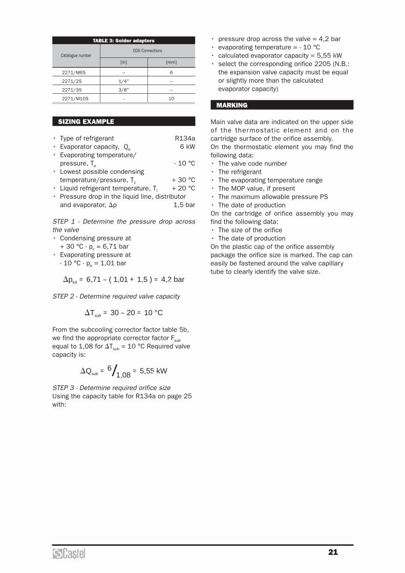
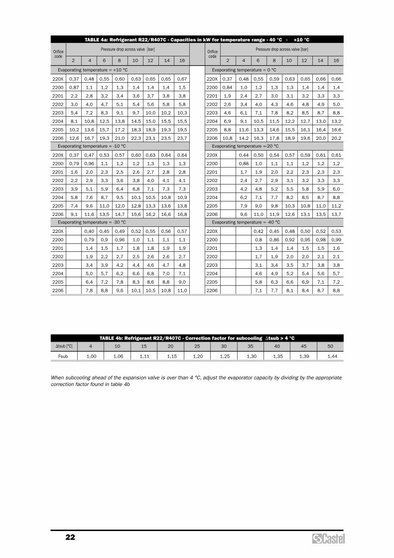
• pressure drop across the valve = 4,2 bar• evaporating temperature = - 10 °C• calculated evaporator capacity = 5,55 kW• select the corresponding orifice 2205 (N.B.:
the expansion valve capacity must be equalor slightly more than the calculatedevaporator capacity)
MARKING
Main valve data are indicated on the upper sideof the thermostatic element and on thecartridge surface of the orifice assembly.On the thermostatic element you may find thefollowing data:• The valve code number• The refrigerant• The evaporating temperature range• The MOP value, if present• The maximum allowable pressure PS• The date of productionOn the cartridge of orifice assembly you mayfind the following data:• The size of the orifice• The date of productionOn the plastic cap of the orifice assemblypackage the orifice size is marked. The cap caneasily be fastened around the valve capillarytube to clearly identify the valve size.
TABLE 3: Solder adapters
Catalogue numberODS Connections
[in] [mm]
2271/M6S
2271/2S
2271/3S
2271/M10S
–
1/4"
3/8"
–
6
–
–
10
SIZING EXAMPLE
• Type of refrigerant R134a• Evaporator capacity, Qe 6 kW• Evaporating temperature/
pressure, Te - 10 °C• Lowest possible condensing
temperature/pressure, Tc + 30 °C• Liquid refrigerant temperature, Tl + 20 °C• Pressure drop in the liquid line, distributor
and evaporator, �p 1,5 bar
STEP 1 - Determine the pressure drop acrossthe valve• Condensing pressure at
+ 30 °C - pc = 6,71 bar• Evaporating pressure at
- 10 °C - pe = 1,01 bar
�ptot = 6,71 – ( 1,01 + 1,5 ) = 4,2 bar
STEP 2 - Determine required valve capacity
�Tsub = 30 – 20 = 10 °C
From the subcooling corrector factor table 5b,we find the appropriate corrector factor Fsub
equal to 1,08 for �Tsub = 10 °C Required valvecapacity is:
�Qsub = 6/1,08 = 5,55 kW
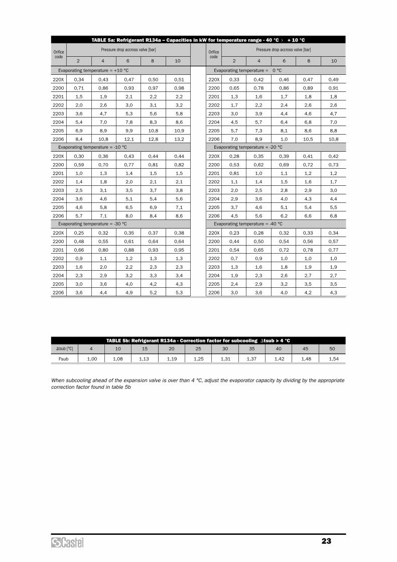
STEP 3 - Determine required orifice sizeUsing the capacity table for R134a on page 25with:
22
TABLE 4a: Refrigerant R22/R407C - Capacities in kW for temperature range - 40 °C › +10 °C
Orifice code
Orificecode
Pressure drop across valve [bar] Pressure drop across valve [bar]
2 4 6 8 10 12 14 16 2 4 6 8 10 12 14 16
Evaporating temperature = 0 °C
220X 0,37 0,48 0,55 0,59 0,63 0,65 0,66 0,66
2200 0,84 1,0 1,2 1,3 1,3 1,4 1,4 1,4
2201 1,9 2,4 2,7 3,0 3,1 3,2 3,3 3,3
2202 2,6 3,4 4,0 4,3 4,6 4,8 4,9 5,0
2203 4,6 6,1 7,1 7,8 8,2 8,5 8,7 8,8
2204 6,9 9,1 10,5 11,5 12,2 12,7 13,0 13,2
2205 8,8 11,6 13,3 14,6 15,5 16,1 16,4 16,6
2206 10,8 14,2 16,3 17,8 18,9 19,6 20,0 20,2
Evaporating temperature =-20 °C
220X 0,44 0,50 0,54 0,57 0,59 0,61 0,61
2200 0,88 1,0 1,1 1,1 1,2 1,2 1,2
2201 1,7 1,9 2,0 2,2 2,3 2,3 2,3
2202 2,4 2,7 2,9 3,1 3,2 3,3 3,3
2203 4,2 4,8 5,2 5,5 5,8 5,9 6,0
2204 6,2 7,1 7,7 8,2 8,5 8,7 8,8
2205 7,9 9,0 9,8 10,3 10,8 11,0 11,2
2206 9,6 11,0 11,9 12,6 13,1 13,5 13,7
Evaporating temperature = -40 °C
220X 0,42 0,45 0,48 0,50 0,52 0,53
2200 0,8 0,86 0,92 0,95 0,98 0,99
2201 1,3 1,4 1,4 1,5 1,5 1,6
2202 1,7 1,9 2,0 2,0 2,1 2,1
2203 3,1 3,4 3,5 3,7 3,8 3,8
2204 4,6 4,9 5,2 5,4 5,6 5,7
2205 5,8 6,3 6,6 6,9 7,1 7,2
2206 7,1 7,7 8,1 8,4 8,7 8,8
Evaporating temperature = +10 °C
220X 0,37 0,48 0,55 0,60 0,63 0,65 0,65 0,67
2200 0,87 1,1 1,2 1,3 1,4 1,4 1,4 1,5
2201 2,2 2,8 3,2 3,4 3,6 3,7 3,8 3,8
2202 3,0 4,0 4,7 5,1 5,4 5,6 5,8 5,8
2203 5,4 7,2 8,3 9,1 9,7 10,0 10,2 10,3
2204 8,1 10,8 12,5 13,8 14,5 15,0 15,5 15,5
2205 10,2 13,6 15,7 17,2 18,3 18,9 19,3 19,5
2206 12,6 16,7 19,3 21,0 22,3 23,1 23,5 23,7
Evaporating temperature = -10 °C
220X 0,37 0,47 0,53 0,57 0,60 0,63 0,64 0,64
2200 0,79 0,96 1,1 1,2 1,2 1,3 1,3 1,3
2201 1,6 2,0 2,3 2,5 2,6 2,7 2,8 2,8
2202 2,2 2,9 3,3 3,6 3,8 4,0 4,1 4,1
2203 3,9 5,1 5,9 6,4 6,8 7,1 7,3 7,3
2204 5,8 7,6 8,7 9,5 10,1 10,5 10,8 10,9
2205 7,4 9,6 11,0 12,0 12,8 13,3 13,6 13,8
2206 9,1 11,6 13,5 14,7 15,6 16,2 16,6 16,8
Evaporating temperature = -30 °C
220X 0,40 0,45 0,49 0,52 0,55 0,56 0,57
2200 0,79 0,9 0,96 1,0 1,1 1,1 1,1
2201 1,4 1,5 1,7 1,8 1,8 1,9 1,9
2202 1,9 2,2 2,7 2,5 2,6 2,6 2,7
2203 3,4 3,9 4,2 4,4 4,6 4,7 4,8
2204 5,0 5,7 6,2 6,6 6,8 7,0 7,1
2205 6,4 7,2 7,8 8,3 8,6 8,8 9,0
2206 7,8 8,8 9,6 10,1 10,5 10,8 11,0
TABLE 4b: Refrigerant R22/R407C - Correction factor for subcooling Dtsub > 4 °C
Dtsub [°C] 4 10 15 20 25 30 35 40 45 50
Fsub 1,00 1,06 1,11 1,15 1,20 1,25 1,30 1,35 1,39 1,44
When subcooling ahead of the expansion valve is over than 4 °C, adjust the evaporator capacity by dividing by the appropriatecorrection factor found in table 4b
23
TABLE 5a: Refrigerant R134a – Capacities in kW for temperature range - 40 °C › + 10 °C
Orificecode
Orificecode
Pressure drop accross valve [bar] Pressure drop accross valve [bar]
2 4 6 8 10 2 4 6 8 10
Evaporating temperature = 0 °C
220X 0,33 0,42 0,46 0,47 0,49
2200 0,65 0,78 0,86 0,89 0,91
2201 1,3 1,6 1,7 1,8 1,8
2202 1,7 2,2 2,4 2,6 2,6
2203 3,0 3,9 4,4 4,6 4,7
2204 4,5 5,7 6,4 6,8 7,0
2205 5,7 7,3 8,1 8,6 8,8
2206 7,0 8,9 1,0 10,5 10,8
Evaporating temperature = -20 °C
220X 0,28 0,35 0,39 0,41 0,42
2200 0,53 0,62 0,69 0,72 0,73
2201 0,81 1,0 1,1 1,2 1,2
2202 1,1 1,4 1,5 1,6 1,7
2203 2,0 2,5 2,8 2,9 3,0
2204 2,9 3,6 4,0 4,3 4,4
2205 3,7 4,6 5,1 5,4 5,5
2206 4,5 5,6 6,2 6,6 6,8
Evaporating temperature = -40 °C
220X 0,23 0,28 0,32 0,33 0,34
2200 0,44 0,50 0,54 0,56 0,57
2201 0,54 0,65 0,72 0,78 0,77
2202 0,7 0,9 1,0 1,0 1,0
2203 1,3 1,6 1,8 1,9 1,9
2204 1,9 2,3 2,6 2,7 2,7
2205 2,4 2,9 3,2 3,5 3,5
2206 3,0 3,6 4,0 4,2 4,3
Evaporating temperature = +10 °C
220X 0,34 0,43 0,47 0,50 0,51
2200 0,71 0,86 0,93 0,97 0,98
2201 1,5 1,9 2,1 2,2 2,2
2202 2,0 2,6 3,0 3,1 3,2
2203 3,6 4,7 5,3 5,6 5,8
2204 5,4 7,0 7,8 8,3 8,6
2205 6,9 8,9 9,9 10,8 10,9
2206 8,4 10,8 12,1 12,8 13,2
Evaporating temperature = -10 °C
220X 0,30 0,36 0,43 0,44 0,44
2200 0,59 0,70 0,77 0,81 0,82
2201 1,0 1,3 1,4 1,5 1,5
2202 1,4 1,8 2,0 2,1 2,1
2203 2,5 3,1 3,5 3,7 3,8
2204 3,6 4,6 5,1 5,4 5,6
2205 4,6 5,8 6,5 6,9 7,1
2206 5,7 7,1 8,0 8,4 8,6
Evaporating temperature = -30 °C
220X 0,25 0,32 0,35 0,37 0,38
2200 0,48 0,55 0,61 0,64 0,64
2201 0,66 0,80 0,88 0,93 0,95
2202 0,9 1,1 1,2 1,3 1,3
2203 1,6 2,0 2,2 2,3 2,3
2204 2,3 2,9 3,2 3,3 3,4
2205 3,0 3,6 4,0 4,2 4,3
2206 3,6 4,4 4,9 5,2 5,3
TABLE 5b: Refrigerant R134a - Correction factor for subcooling Dtsub > 4 °C
Dtsub [°C] 4 10 15 20 25 30 35 40 45 50
Fsub 1,00 1,08 1,13 1,19 1,25 1,31 1,37 1,42 1,48 1,54
When subcooling ahead of the expansion valve is over than 4 °C, adjust the evaporator capacity by dividing by the appropriatecorrection factor found in table 5b

24
TABLE 6a: Refrigerant R404A/R507 – Capacities in kW for temperature range - 40 °C › + 10 °C
Orificecode
Orificecode
Pressure drop across valve [bar] Pressure drop across valve [bar]
2 4 6 8 10 12 14 16 2 4 6 8 10 12 14 16
Evaporating temperature = 0 °C
220X 0,30 0,37 0,41 0,42 0,43 0,43 0,43 0,41
2200 0,68 0,80 0,87 0,90 0,92 0,93 0,91 0,87
2201 1,53 1,86 2,04 2,13 2,18 2,18 2,15 2,08
2202 2,06 2,64 2,95 3,13 3,22 3,25 3,21 3,11
2203 3,68 4,72 5,27 5,59 5,75 5,80 5,73 5,55
2204 5,49 7,15 7,86 8,33 8,58 8,64 8,53 8,27
2205 6,97 8,92 9,95 10,52 10,83 10,90 10,76 10,43
2206 8,57 10,93 12,16 12,85 13,21 13,30 13,12 12,72
Evaporating temperature = -20 °C
220X 0,35 0,38 0,40 0,39 0,40 0,39 0,38
2200 0,70 0,75 0,77 0,79 0,79 0,79 0,76
2201 1,34 1,45 1,50 1,52 1,52 1,51 1,47
2202 1,85 2,04 2,14 2,17 2,18 2,16 2,09
2203 3,32 3,66 3,83 3,89 3,90 3,86 3,75
2204 4,88 5,40 5,64 5,75 5,77 5,71 5,56
2205 6,20 6,86 7,17 7,29 7,31 7,23 7,05
2206 7,60 8,39 8,75 8,91 8,93 8,84 8,61
Evaporating temperature = -40 °C
220X 0,32 0,33 0,33 0,33 0,32 0,32
2200 0,60 0,61 0,62 0,61 0,60 0,59
2201 0,92 0,96 0,97 0,96 0,94 0,91
2202 1,27 1,32 1,33 1,31 1,28 1,24
2203 2,28 2,36 2,38 2,36 2,31 2,24
2204 3,34 3,47 3,50 3,48 3,42 3,33
2205 4,25 4,41 4,45 4,43 4,36 4,24
2206 5,19 5,39 5,45 5,42 5,33 5,19
Evaporating temperature = +10 °C
220X 0,28 0,35 0,40 0,42 0,43 0,43 0,42 0,41
2200 0,67 0,82 0,90 0,94 0,96 0,96 0,93 0,90
2201 1,70 2,10 2,30 2,42 2,48 2,46 2,41 2,34
2202 2,32 3,00 3,39 3,61 3,73 3,74 3,68 3,59
2203 4,15 5,36 6,03 6,43 6,63 6,66 6,55 6,39
2204 6,24 8,06 9,06 9,66 9,95 9,98 9,81 9,57
2205 7,91 10,17 11,43 12,16 12,53 12,56 12,34 12,03
2206 9,71 12,47 13,98 14,86 15,29 15,31 15,05 14,66
Evaporating temperature = -10 °C
220X 0,30 0,37 0,40 0,42 0,42 0,42 0,41 0,41
2200 0,65 0,76 0,82 0,84 0,87 0,87 0,85 0,83
2201 1,31 1,61 1,74 1,81 1,84 1,85 1,84 1,78
2202 1,76 2,24 2,50 2,62 2,69 2,71 2,68 2,60
2203 3,14 4,02 4,47 4,69 4,81 4,84 4,79 4,65
2204 4,66 5,97 6,61 6,95 7,13 7,18 7,11 6,91
2205 5,93 7,57 8,39 8,81 9,02 9,08 8,99 8,73
2206 7,28 9,27 10,26 10,76 11,00 11,08 10,97 10,65
Evaporating temperature = -30 °C
220X 0,35 0,37 0,36 0,37 0,36 0,35
2200 0,67 0,70 0,70 0,70 0,69 0,67
2201 1,18 1,21 1,23 1,21 1,20 1,17
2202 1,63 1,69 1,71 1,70 1,68 1,64
2203 2,93 3,04 3,07 3,06 3,02 2,93
2204 4,28 4,47 4,52 4,51 4,46 4,35
2205 5,45 5,68 5,74 5,74 5,67 5,52
2206 6,66 6,94 7,02 7,01 6,93 6,75
TABLE 6b: Refrigerant R404A/R507 - Correction factor for subcooling Dtsub > 4 °C
Dtsub [°C] 4 10 15 20 25 30 35 40 45 50
Fsub 1,00 1,10 1,20 1,29 1,37 1,46 1,54 1,63 1,70 1,78
When subcooling ahead of the expansion valve is over than 4 °C, adjust the evaporator capacity by dividing by the appropriatecorrection factor found in table 6b

25
TABLE 7a: Refrigerant R404A/R507 – Capacities in kW for temperature range - 60 °C › - 25 °C
Orificecode
Orificecode
Pressure drop across valve [bar] Pressure drop across valve [bar]
2 4 6 8 10 12 14 16 2 4 6 8 10 12 14 16
Evaporating temperature = -30 °C
2200 0,53 0,64 0,67 0,70 0,70 0,70 0,69 0,67
2201 0,88 1,07 1,18 1,21 1,23 1,21 1,20 1,17
2202 1,18 1,47 1,63 1,69 1,71 1,70 1,68 1,64
2203 2,12 2,65 2,93 3,04 3,07 3,05 3,02 2,93
2204 3,09 3,88 4,28 4,47 4,52 4,51 4,46 4,35
2205 3,94 4,94 5,45 5,68 5,74 5,74 5,67 5,52
2206 4,83 6,06 6,66 6,94 7,02 7,01 6,93 6,75
Evaporating temperature = -50 °C
2200 0,49 0,53 0,54 0,54 0,53 0,52 0,50
2201 0,51 0,57 0,60 0,60 0,60 0,60 0,59
2202 0,91 0,99 1,02 1,02 1,01 0,98 0,95
2203 1,63 1,73 1,84 1,84 1,81 1,78 1,72
2204 2,36 2,60 2,69 2,71 2,68 2,63 2,56
2205 3,02 3,30 3,43 3,45 3,42 3,35 3,26
2206 3,69 4,04 4,20 4,22 4,18 4,12 4,00
Evaporating temperature = -25 °C
2200 0,57 0,67 0,72 0,73 0,74 0,85 0,74 0,71
2201 0,98 1,20 1,31 1,36 1,37 1,37 1,35 1,31
2202 1,31 1,65 1,83 1,91 1,93 1,93 1,90 1,85
2203 2,35 2,97 3,28 3,42 3,47 3,46 3,42 3,32
2204 3,45 4,37 4,82 5,04 5,11 5,12 5,06 4,93
2205 4,40 5,56 6,14 6,40 6,49 6,49 6,42 6,26
2206 5,40 6,30 7,49 7,81 7,93 7,93 7,85 7,64
Evaporating temperature = -40 °C
2200 0,56 0,60 0,61 0,62 0,61 0,60 0,59
2201 0,65 0,72 0,75 0,77 0,77 0,77 0,75
2202 1,17 1,27 1,32 1,33 1,31 1,28 1,24
2203 2,09 2,28 2,36 2,38 2,36 2,31 2,24
2204 3,03 3,34 3,47 3,50 3,48 3,42 3,33
2205 3,87 4,25 4,41 4,45 4,43 4,36 4,24
2206 4,73 5,19 5,39 5,45 5,47 5,33 5,19
Evaporating temperature = -60 °C
2200 0,46 0,48 0,47 0,45 0,45 0,43
2201 0,58 0,60 0,60 0,58 0,56 0,54
2202 0,78 0,80 0,80 0,78 0,75 0,72
2203 1,40 1,44 1,43 1,40 1,36 1,30
2204 2,04 2,11 2,11 2,07 2,03 1,96
2205 2,59 2,69 2,66 2,65 2,59 2,50
2206 3,16 3,28 3,30 3,25 3,18 3,07
TABLE 7b: Refrigerant R404A/R507 - Correction factor for subcooling Dtsub > 4 °C
Dtsub [°C] 4 10 15 20 25 30 35 40 45 50
Fsub 1,00 1,10 1,20 1,29 1,37 1,46 1,54 1,63 1,70 1,78
When subcooling ahead of the expansion valve is over than 4 °C, adjust the evaporator capacity by dividing by the appropriatecorrection factor found in table 7b

26
PWM SOLENOID EXPANSION VALVE WITH INTERCHANGEABLE ORIFICE
APPLICATION
Solenoid expansion valve Castel type 2028regulates the refrigerant flow into theevaporator by modulating the opening timephase of the plug and so permitting a widerange of power.This valve must be used with a coil type HM4(see table 2), controlled by an electronicregulator device (not supplied by Castel).This valve is most frequently used inrefrigeration systems, in particular refrigeratedcabinets in the supermarket, which userefrigerant fluids proper to the Group II (asdefined in Article 9, Section 2.2 of Directive97/23/CE, and referred in Directive67/548/CE).
OPERATION
Valve type 2028 is a lamination device thatreceives liquid from the condenser and injectsit into the evaporator, operating the necessarypressure drop across the expansion orifice.It’s an ON/OFF valve that must be regulatedwith the Pulse Width Modulation (PWM)method and it can be actuated by a very simpleelectronic controller. In according to the PWMmethod, the evaporator refrigerant capacity QT,required in a fixed period “T”, is delivered bythe valve in a time interval “t”, shorter than“T”. During the period “t” the valve opens andpermits maximum flow (ON phase); in theremaining period “T-t” the valve closes with noflow (OFF phase).For an effective PWM regulation, the valve mustbe sized in such a way that in the hardestconditions of the system, the orifice of thevalve is big enough to deliver the refrigerantrequested; in these extreme conditions thevalve will last opened for the entire period “T”.The use of an electronic regulator allows amore accurate metering of the refrigerantreaching a greater efficiency (and then asensible decrement of the machinerymanagement costs) and a faster response tothe variations of the evaporation load.
CONSTRUCTION
Valve is supplied complete with its orifice; thereare seven different orifices corresponding toseven different evaporator capacities , thatincrease passing from orifice 01 to orifice 07.The last two numbers in the code identify whatsize of orifice has been mounted on the valveinto the factory; for example the code2028/3S02 identifies a valve with 3/8” solderconnections, size 02 orifice. The orifices areinterchangeable and can be mounted even ifthe valve is soldered on the system; in thiscase use the corresponding spare parts kit, inaccording to table 3.
The main parts of the valves are made with thefollowing materials:• Hot forged brass EN 12420 – CW 617N for
body and the housing pipe of the mobile plug• Copper tube EN 12735-1 – Cu-DHP for solder
connections• Austenitic stainless steel EN 10088-3 –
1.4301 for the filter• Ferritic stainless steel EN 10088-3 – 1.4105
for mobile and fixed plugs• Austenitic stainless steel EN 10088-3 –
1.4305 for orifices• Chloroprene rubber (CR) for outlet seal
gaskets• P.T.F.E. for seat gaskets
COILS AND CONNECTORS
Coils type HM4 must be mounted on thesevalves. Table 2 presents the most importantcharacteristics of coils and correspondingconnectors. For further technical characteristicsabout HM4 coils and their connectors see tothe “solenoid valve” chapter.
SELECTION
To correctly select a solenoid expansion valveon a refrigerating system, the following designconditions must be available:• Type of refrigerant• Evaporator capacity, Qe
• Evaporating temperature/pressure, Te / pe
• Lowest possible condensingtemperature/pressure, Tc / pc
• Liquid refrigerant temperature, Tl
• Pressure drop in the liquid line, distributorand evaporator, ∆p
27
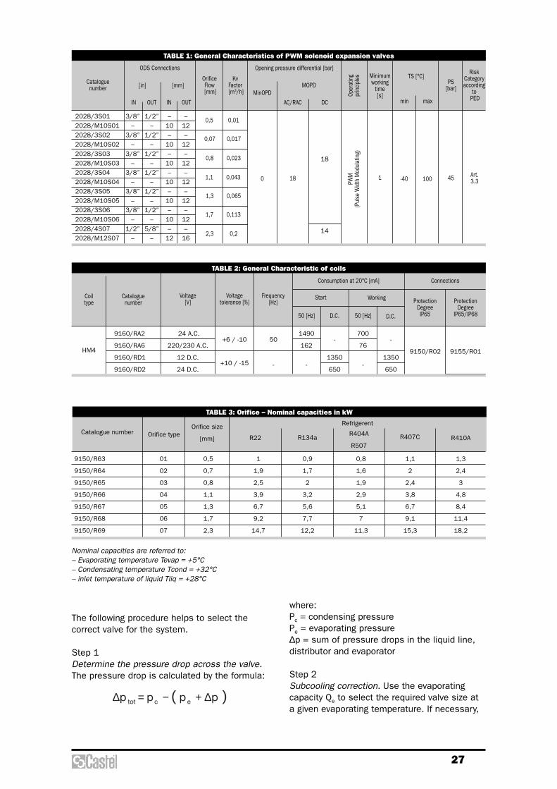
TABLE 1: General Characteristics of PWM solenoid expansion valves
Cataloguenumber
0,5 0,01
0,07 0,017
0,8 0,023
1,1 0,043
1,3 0,065
1,7 0,113
2,3 0,2
OrificeFlow[mm]
KvFactor[m3/h] MinOPD
0 18
PWM
(Pul
se W
idth
Mod
ulat
ing)
1 -40 100 45 Art. 3.3
MOPD
AC/RAC DC
Oper
atin
g pr
incip
les Minimum
workingtime[s]
Opening pressure differential [bar]
min max
PS [bar]
TS [°C]ODS Connections
[mm][in]
IN OUT IN OUT
RiskCategoryaccording
toPED
2028/3S01 3/8” 1/2” – –2028/M10S01 – – 10 122028/3S02 3/8” 1/2” – –2028/M10S02 – – 10 122028/3S03 3/8” 1/2” – –2028/M10S03 – – 10 122028/3S04 3/8” 1/2” – –2028/M10S04 – – 10 122028/3S05 3/8” 1/2” – –2028/M10S05 – – 10 122028/3S06 3/8” 1/2” – –2028/M10S06 – – 10 122028/4S07 1/2” 5/8” – –2028/M12S07 – – 12 16
18
14
Nominal capacities are referred to:– Evaporating temperature Tevap = +5°C– Condensating temperature Tcond = +32°C– inlet temperature of liquid Tliq = +28°C
The following procedure helps to select thecorrect valve for the system.
Step 1Determine the pressure drop across the valve.The pressure drop is calculated by the formula:
( )pppp ectot ∆+−=∆
where:Pc = condensing pressurePe = evaporating pressure∆p = sum of pressure drops in the liquid line,distributor and evaporator
Step 2Subcooling correction. Use the evaporatingcapacity Qe to select the required valve size ata given evaporating temperature. If necessary,
TABLE 2: General Characteristic of coils
Coiltype Protection
DegreeIP65
ProtectionDegree
IP65/IP68
ConnectionsConsumption at 20°C [mA]
Start
50 [Hz] D.C. 50 [Hz] D.C.
WorkingFrequency[Hz]
Voltage tolerance [%]
Voltage[V]
Cataloguenumber
HM4
9160/RA2
9160/RA6
9160/RD1
9160/RD2
24 A.C.
220/230 A.C.
12 D.C.
24 D.C.
1490
162
-
700
76
-
-
1350
650
-
1350
650
+6 / -10
+10 / -15
50
-
9155/R019150/R02
TABLE 3: Orifice – Nominal capacities in kW
Catalogue numberRefrigerent
Orifice typeOrifice size
[mm] R22 R134aR404A
R507R407C R410A
9150/R63 01 0,5 1 0,9 0,8 1,1 1,3
9150/R64 02 0,7 1,9 1,7 1,6 2 2,4
9150/R65 03 0,8 2,5 2 1,9 2,4 3
9150/R66 04 1,1 3,9 3,2 2,9 3,8 4,8
9150/R67 05 1,3 6,7 5,6 5,1 6,7 8,4
9150/R68 06 1,7 9,2 7,7 7 9,1 11,4
9150/R69 07 2,3 14,7 12,2 11,3 15,3 18,2
28
a given evaporating temperature. If necessary,correct the evaporator capacity for subcooling.Subcooling liquid refrigerant entering theevaporator increase the evaporator capacity, sothat a smaller valve may be required. Thesubcooling is calculated by the formula:
From the subcooling corrector factor table findthe appropriate corrector factor Fsub
corresponding to the ∆Tsub calculated anddetermine the required valve capacity by theformula:
Qsub = Fsub. Qe
Step 3Application correction. To obtain a correctregulation with this valve, is necessar y tooversize it so its closing period is between the25% and the 50% of the total period T of theregulator. The correct choice of this closingperiod depends on the application, that canhave peaks of load, and on the criterion used bythe electronic regulator. Generally, anyway, this correcting factor Fev isstr ict ly dependent by the evaporationtemperature so it be assumed that Fev = 1.25for Tev >= -15°C and Fev = 1.50 for Tev<=-15°C.These generic instructions must be verified onthe real application.
The capacity of the valve will have therefore tobe at least equal to:
Qev = Fev. Qsub
Step 4Determine required orifice size. Use thepressure drop across the valve, the evaporatingtemperature and the calculated evaporatorcapacity Qe to select the corresponding orificesize from the capacity table corresponding tothe chosen refrigerant.
Step 5Liquid line sizing. Since the 2028 is an ON/OFFvalve, during the opening phase of the valve,the flow rate can be too much higher than themean flow rate. For this reason the designermust size the diameter of the pipes of theliquid line in according to the maximum flowrate across the orifice in the effectiveconditions of ∆Ptot and so avoiding thedecrement of the valve capacity due to thepressure drop.
lcsub TTT −=∆
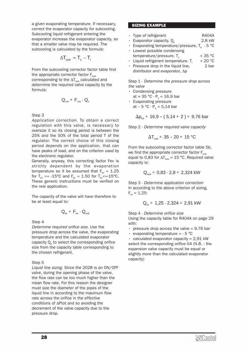
SIZING EXAMPLE
• Type of refrigerant R404A• Evaporator capacity, Qe 2,8 kW• Evaporating temperature/pressure, Te - 5 °C• Lowest possible condensing
temperature/pressure, Tc + 35 °C• Liquid refrigerant temperature, Tl + 20 °C• Pressure drop in the liquid line, 2 bar
distributor and evaporator, ∆p
Step 1 - Determine the pressure drop acrossthe valve• Condensing pressure
at + 35 °C - Pc = 16,9 bar• Evaporating pressure
at – 5 °C - Pe = 5,14 bar
�ptot = 16,9 – ( 5,14 + 2 ) = 9,76 bar
Step 2 - Determine required valve capacity
�Tsub = 35 – 20 = 15 °C
From the subcooling corrector factor table 5b,we find the appropriate corrector factor Fsub
equal to 0,83 for ∆Tsub = 15 °C. Required valvecapacity is:
Qsub = 0,83 . 2,8 = 2,324 kW
Step 3 - Determine application correctionIn according to the above criterion of sizing, Fev = 1,25:
Qev = 1,25 . 2,324 = 2,91 kW
Step 4 - Determine orifice sizeUsing the capacity table for R404A on page 29with:• pressure drop across the valve = 9,76 bar• evaporating temperature = - 5 °C• calculated evaporator capacity = 2,91 kWselect the corresponding orifice 04 (N.B. : theexpansion valve capacity must be equal orslightly more than the calculated evaporatorcapacity)

29
TABLE 4: Refrigerant R22 – Capacities in kW
2
Pressure drop across valve [bar] Orifice
type 4 6 8 10 12 14 16 18
01 0,7 0,9 1,0 1,1 1,2 1,2 1,2 1,2 1,2
02 1,3 1,7 1,9 2,2 2,2 2,3 2,3 2,4 2,3
03 1,7 2,2 2,5 2,7 2,8 2,9 2,9 2,9 2,9
04 2,7 3,4 3,9 4,2 4,4 4,5 4,6 4,7 4,7
05 4,6 6,0 6,7 7,2 7,6 7,9 8,0 8,1 8,1
06 6,3 8,1 9,2 9,9 10,4 10,6 10,9 11,0 11,1
07 10,1 13,0 14,7 15,8 16,6 17,0 17,4 17,6 (1) 17,4 (2)
TABLE 5: Refrigerant R134a – Capacities in kW
2
Pressure drop across valve [bar] Orifice
type 4 6 8 10 12 14 16 18
01 0,6 0,8 0,9 0,9 0,9 0,9 0,9 0,9 0,9
02 1,1 1,4 1,7 1,7 1,8 1,8 1,8 1,8 1,7
03 1,4 1,8 2,0 2,2 2,2 2,3 2,3 2,2 2,2
04 2,3 2,9 3,2 3,4 3,5 3,6 3,6 3,5 3,4
05 3,9 5,0 5,6 6,0 6,2 6,2 6,2 6,2 6,0
06 5,3 6,8 7,7 8,1 8,4 8,5 8,5 8,4 8,1
07 8,5 10,9 12,2 13,0 13,3 13,5 13,5 13,3 (1) 13 (2)
TABLE 6: Refrigerant R404A/R507 – Capacities in kW
2
Pressure drop across valve [bar] Orifice
type 4 6 8 10 12 14 16 18
01 0,6 0,7 0,8 0,8 0,9 0,8 0,8 0,8 0,8
02 1,1 1,3 1,6 1,6 1,7 1,7 1,6 1,6 1,4
03 1,3 1,7 1,9 2,0 2,0 2,0 2,0 1,9 1,8
04 2,2 2,8 2,9 3,1 3,2 3,2 3,1 3,1 2,9
05 3,8 4,7 5,1 5,5 5,6 5,6 5,6 5,4 5,1
06 5,0 6,4 7,0 7,4 7,6 7,7 7,6 7,4 6,9
07 8,1 10,3 11,3 11,9 12,2 12,2 12,1 11,8 (1) 11,2 (2)
TABLE 7: Refrigerant R407C – Capacities in kW
2
Pressure drop across valve [bar] Orifice
type 4 6 8 10 12 14 16 18
01 0,7 1,0 1,1 1,1 1,2 1,2 1,2 1,2 1,2
02 1,4 1,8 2,0 2,0 2,3 2,3 2,4 2,4 2,3
03 1,7 2,3 2,4 2,7 2,8 2,9 2,9 2,9 2,9
04 2,9 3,6 3,8 4,3 4,5 4,6 4,7 4,7 4,7
05 4,9 6,2 6,7 7,5 7,8 7,9 8,1 8,1 8,0
06 6,7 8,5 9,1 10,2 10,5 10,8 11,0 11,0 10,9
07 10,7 13,6 15,3 15,7 16,9 17,2 17,6 17,6 (1) 17,2 (2)
(1) Pressure differential not available with coils 9160/RD2
(2) Pressure differential not available with coils 9160/RD1 and 9160/RD2
30
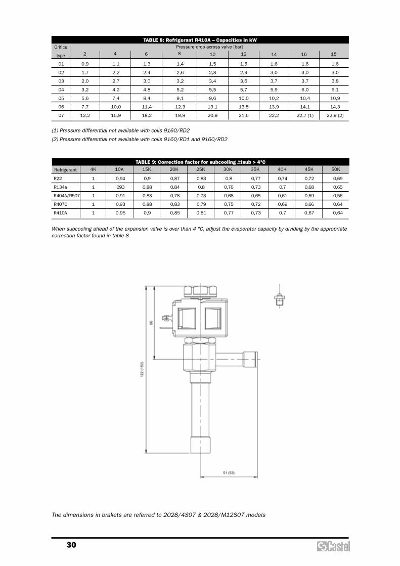
TABLE 8: Refrigerant R410A – Capacities in kW
2
Pressure drop across valve [bar] Orifice
type 4 6 8 10 12 14 16 18
01 0,9 1,1 1,3 1,4 1,5 1,5 1,6 1,6 1,6
02 1,7 2,2 2,4 2,6 2,8 2,9 3,0 3,0 3,0
03 2,0 2,7 3,0 3,2 3,4 3,6 3,7 3,7 3,8
04 3,2 4,2 4,8 5,2 5,5 5,7 5,9 6,0 6,1
05 5,6 7,4 8,4 9,1 9,6 10,0 10,2 10,4 10,9
06 7,7 10,0 11,4 12,3 13,1 13,5 13,9 14,1 14,3
07 12,2 15,9 18,2 19,8 20,9 21,6 22,2 22,7 (1) 22,9 (2)
TABLE 9: Correction factor for subcooling ∆tsub > 4°C4KRefrigerant 10K 15K 20K 25K 30K 35K 40K 45K 50K
R22 1 0,94 0,9 0,87 0,83 0,8 0,77 0,74 0,72 0,69
R134a 1 093 0,88 0,84 0,8 0,76 0,73 0,7 0,68 0,65
R404A/R507 1 0,91 0,83 0,78 0,73 0,68 0,65 0,61 0,59 0,56
R407C 1 0,93 0,88 0,83 0,79 0,75 0,72 0,69 0,66 0,64
R410A 1 0,95 0,9 0,85 0,81 0,77 0,73 0,7 0,67 0,64
When subcooling ahead of the expansion valve is over than 4 °C, adjust the evaporator capacity by dividing by the appropriatecorrection factor found in table 8
(1) Pressure differential not available with coils 9160/RD2
(2) Pressure differential not available with coils 9160/RD1 and 9160/RD2
The dimensions in brakets are referred to 2028/4S07 & 2028/M12S07 models
Solenoid valves
32
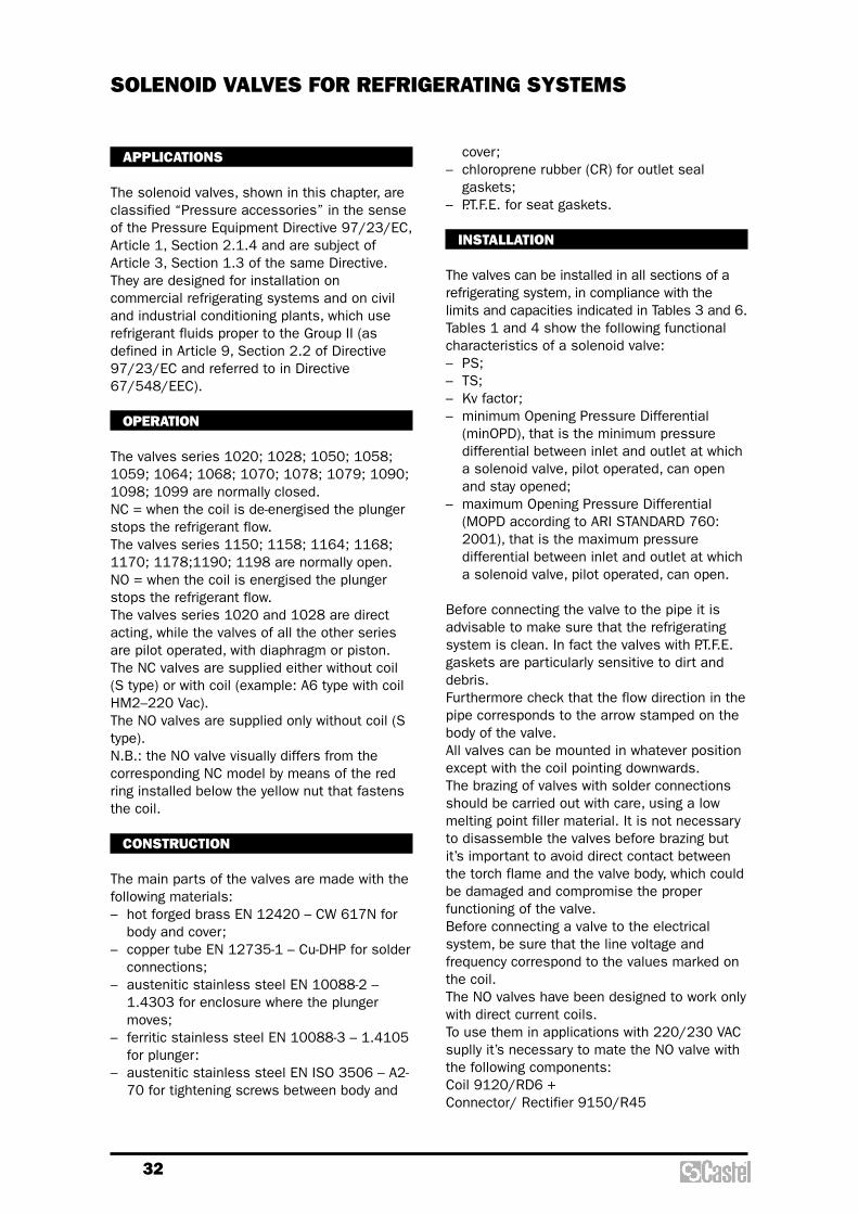
cover;– chloroprene rubber (CR) for outlet seal
gaskets;– P.T.F.E. for seat gaskets.
INSTALLATION
The valves can be installed in all sections of arefrigerating system, in compliance with thelimits and capacities indicated in Tables 3 and 6. Tables 1 and 4 show the following functionalcharacteristics of a solenoid valve:– PS;– TS;– Kv factor;– minimum Opening Pressure Differential
(minOPD), that is the minimum pressuredifferential between inlet and outlet at whicha solenoid valve, pilot operated, can openand stay opened;
– maximum Opening Pressure Differential(MOPD according to ARI STANDARD 760:2001), that is the maximum pressuredifferential between inlet and outlet at whicha solenoid valve, pilot operated, can open.
Before connecting the valve to the pipe it isadvisable to make sure that the refrigeratingsystem is clean. In fact the valves with P.T.F.E.gaskets are particularly sensitive to dirt anddebris. Furthermore check that the flow direction in thepipe corresponds to the arrow stamped on thebody of the valve. All valves can be mounted in whatever positionexcept with the coil pointing downwards. The brazing of valves with solder connectionsshould be carried out with care, using a lowmelting point filler material. It is not necessaryto disassemble the valves before brazing butit’s important to avoid direct contact betweenthe torch flame and the valve body, which couldbe damaged and compromise the properfunctioning of the valve.Before connecting a valve to the electricalsystem, be sure that the line voltage andfrequency correspond to the values marked onthe coil.The NO valves have been designed to work onlywith direct current coils. To use them in applications with 220/230 VACsuplly it’s necessary to mate the NO valve withthe following components:Coil 9120/RD6 +Connector/ Rectifier 9150/R45
APPLICATIONS
The solenoid valves, shown in this chapter, areclassified “Pressure accessories” in the senseof the Pressure Equipment Directive 97/23/EC,Article 1, Section 2.1.4 and are subject ofArticle 3, Section 1.3 of the same Directive.They are designed for installation oncommercial refrigerating systems and on civiland industrial conditioning plants, which userefrigerant fluids proper to the Group II (asdefined in Article 9, Section 2.2 of Directive97/23/EC and referred to in Directive67/548/EEC).
OPERATION
The valves series 1020; 1028; 1050; 1058;1059; 1064; 1068; 1070; 1078; 1079; 1090;1098; 1099 are normally closed. NC = when the coil is de-energised the plungerstops the refrigerant flow.The valves series 1150; 1158; 1164; 1168;1170; 1178;1190; 1198 are normally open. NO = when the coil is energised the plungerstops the refrigerant flow.The valves series 1020 and 1028 are directacting, while the valves of all the other seriesare pilot operated, with diaphragm or piston.The NC valves are supplied either without coil(S type) or with coil (example: A6 type with coilHM2–220 Vac). The NO valves are supplied only without coil (Stype).N.B.: the NO valve visually differs from thecorresponding NC model by means of the redring installed below the yellow nut that fastensthe coil.
CONSTRUCTION
The main parts of the valves are made with thefollowing materials:– hot forged brass EN 12420 – CW 617N for
body and cover;– copper tube EN 12735-1 – Cu-DHP for solder
connections;– austenitic stainless steel EN 10088-2 –
1.4303 for enclosure where the plungermoves;
– ferritic stainless steel EN 10088-3 – 1.4105for plunger:
– austenitic stainless steel EN ISO 3506 – A2-70 for tightening screws between body and
SOLENOID VALVES FOR REFRIGERATING SYSTEMS

33
TABLE 1a: General Characteristics of NC valves (normally closed) with SAE Flare connections
Cataloguenumber SAE
Flare
1/4"
3/8"
3/8"
1/2"
1/2"
5/8"
5/8"
3/4"
5/8"
3/4"
2,5
3
7
12,5
16,5
0,175
0,23
0,80
2,20
2,61
3,80
4,80
3,80
4,80
0
0,05
0,07
0,05
25
(3)
21
19
18
13
– 35
+105
(1)
+110
(2)
+105
(1)
45 Art. 3.3
ConnectionsSeat sizeNominal
Ø [mm]
KvFactor[m3/h]
Operating Principles min
OPD
MOPDCoil type
Opening Pressure Differential [bar]
HM4(AC)
21
HM2CM2(AC)
HM3(DC)
min.
TS [°C]
max.
PS[bar]
RiskCategory
according to PED
DirectActing
DiaphragmPilot
Operated
1020/2
1020/3
1064/3
1064/4
1070/4
1070/5
1050/5
1050/6
1090/5
1090/6
PistonPilot
Operated
DiaphragmPilot
Operated
(1) Temperature peaks of 120 °C are allowed during defrosting.(2) Temperature peaks of 130 °C are allowed during defrosting.(3) For information about higher MOPD, please contact Castel Technical Departement.
TABLE 1b: General Characteristics of NC valves (normally closed) with ODS connections
Cataloguenumber
1/4"
1/4"
3/8"
–
3/8"
–
–
1/2"
–
1/2"
5/8"
7/8"
5/8"
3/4"
7/8"
1.1/8"
5/8"
3/4"
7/8"
1.1/8"
1.1/8"
1.3/8"
1.1/8"
1.3/8"
1.3/8"
1.5/8"
–
–
–
–
10
–
10
12
–
12
–
16
22
16
–
22
–
16
–
22
–
–
35
–
35
35
–
42
2,2
3
7
12,5
16,5
25,5
25
27
0,15
0,23
0,80
2,20
2,61
3,80
4,80
5,70
3,80
4,80
5,70
10
10
16
0
0,05
0,07
0,05
0,07
25
(3)
21
25
(3)
19
18
13
19
– 35
+105
(1)
+110
(2)
+105
(1)
+110
(2)
45 Art. 3.3
Ø[in.]
Ø[mm]
ODS
ConnectionsSeat sizeNominal
Ø [mm]
KvFactor[m3/h]
Operating Principles min
OPD
MOPDCoil type
Opening Pressure Differential [bar]
HM4(AC)
21
HM2CM2(AC)
HM3(DC)
min.
TS [°C]
max.
PS[bar]
RiskCategory
according toPED
Dire
ct A
ctin
gD
iaph
ragm
Pilo
t O
pera
ted
1028/2
1028/2E
1028/3
1028/M10
1068/3
1068/M10
1068/M12
1068/4
1078/M12
1078/4
1078/5
1079/7
1058/5
1058/6
1058/7
1059/9
1098/5
1098/6
1098/7
1099/9
1078/9
1079/11
1098/9
1099/11
1078/11
1079/13
1079/M42
(1) Temperature peaks of 120 °C are allowed during defrosting.(2) Temperature peaks of 130 °C are allowed during defrosting.(3) For information about higher MOPD, please contact Castel Technical Departement.
Pist
on P
ilot
Ope
rate
dD
iaph
ragm
Pilo
tO
pera
ted
Pist
on P
ilot
Ope
rate
d

34
SOLENOID VALVES FOR REFRIGERATING SYSTEMS
TABLE 2: Dimensions and Weights of NC valves with 9100 coil (1)
Catalogue number
Weight[g]
H1 H2 H3 L1 L2 Q
75
82
91
121
106
115
157
175
62,5
69,5
75
93
78
96
127
141
34
40
47
65
50
72
99
113
58
65
125
125
125
125
68
72
111
111
127
127
100
106
127
127
175
190
120
124
175
175
180
216
120
124
175
175
180
216
250
292
235
277
278
50
–
–
45
57
80
68
80
340
355
350
350
365
365
400
415
400
395
420
420
710
755
690
680
775
765
1157
1487
1117
1307
1292
1347
1035
1365
995
1185
1170
1225
2565
2620
2050
2130
2710
2750
2750
Dimensions [mm]
1020/2
1020/3
1028/2
1028/2E
1028/3
1028/M10
1064/3
1064/4
1068/3
1068/M10
1068/M12
1068/4
1070/4
1070/5
1078/M12
1078/4
1078/5
1079/7
1050/5
1050/6
1058/5
1058/6
1058/7
1059/9
1090/5
1090/6
1098/5
1098/6
1098/7
1099/9
1078/9
1079/11
1098/9
1099/11
1078/11
1079/13
1079/M42
(1) With coil type 9120 the dimension L2 is equal to 64 mm and the valves weights must be increased of 305 g.

35
Connectors are not included in the boxes and have to be ordered separately.

36
SOLENOID VALVES FOR REFRIGERATING SYSTEMS
TABLE 3: Refrigerant Flow Capacity of NC valves
Cataloguenumber
R134a R22 R407C R404A R134a R22 R407C R404A R134a R22 R407C R404A
Liquid Vapour Hot Gas
Refrigerant Flow Capacity [kW]
1020/2
1020/3
1028/2
1028/2E
1028/3
1028/M10
1064/3
1064/4
1068/3
1068/M10
1068/M12
1068/4
1070/4
1070/5
1078/M12
1078/4
1078/5
1079/7
1050/5
1050/6
1058/5
1058/6
1058/7
1059/9
1090/5
1090/6
1098/5
1098/6
1098/7
1099/9
1078/9
1079/11
1098/9
1099/11
1078/11
1079/13
1079/M42
2,95
3,88
2,53
3,88
13,5
37,1
44,0
37,1
44,0
64,0
80,9
64,0
80,9
96,0
64,0
80,9
64,0
80,9
96,0
168,5
168,5
269,6
3,15
4,14
2,70
4,14
14,4
39,6
47,0
39,6
47,0
68,4
86,4
68,4
86,4
102,6
68,4
86,4
68,4
86,4
102,6
180,0
180,0
288,0
3,28
4,31
2,81
4,31
15,0
41,2
48,9
41,2
48,9
71,2
90,0
71,2
90,0
106,8
71,2
90,0
71,2
90,0
106,8
187,4
187,4
299,8
2,08
2,74
1,79
2,74
9,5
26,2
31,1
26,2
31,1
45,2
57,1
45,2
57,1
67,8
45,2
57,1
45,2
57,1
67,8
119,0
119,0
190,4
R410A
3,33
4,38
2,86
4,38
15,2
41,9
49,7
41,9
49,7
72,4
91,4
72,4
91,4
108,5
72,4
91,4
72,4
91,4
108,5
190,4
190,4
304,6
–
1,73
4,75
5,64
4,75
5,64
8,2
10,4
8,2
10,4
12,3
8,2
10,4
8,2
10,4
12,3
21,6
21,6
34,6
–
2,16
5,94
7,05
5,94
7,05
10,3
13,0
10,3
13,0
15,4
10,3
13,0
10,3
13,0
15,4
27,0
27,0
43,2
–
2,14
5,90
6,99
5,90
6,99
10,2
12,9
10,2
12,9
15,3
10,2
12,9
10,2
12,9
15,3
26,8
26,8
42,9
–
1,81
4,97
5,90
4,97
5,90
8,6
10,8
8,6
10,8
12,9
8,6
10,8
8,6
10,8
12,9
22,6
22,6
36,2
R410A
–
2,88
7,92
9,40
7,92
9,40
13,7
17,3
13,7
17,3
20,5
13,7
17,3
13,7
17,3
20,5
36,0
36,0
57,6
1,49
1,96
1,28
1,96
6,8
18,7
22,2
18,7
22,2
32,3
40,8
32,3
40,8
48,5
32,3
40,8
32,3
40,8
48,5
85,0
85,0
136,0
2,05
2,69
1,76
2,69
9,4
25,7
30,5
25,7
30,5
44,5
56,2
44,5
56,2
66,7
44,5
56,2
44,5
56,2
66,7
117,0
117,0
187,2
2,03
2,67
1,74
2,67
9,3
25,6
30,3
25,6
30,3
44,2
55,8
44,2
55,8
66,2
44,2
55,8
44,2
55,8
66,2
116,2
116,2
185,9
1,75
2,30
1,50
2,30
8,0
22,0
26,1
22,0
26,1
38,0
48,0
38,0
48,0
57,0
38,0
48,0
38,0
48,0
57,0
100,0
100,0
160,0
R410A
2,28
2,99
1,95
2,99
10,4
28,6
33,9
28,6
33,9
49,4
62,4
49,4
62,4
74,1
49,4
62,4
49,4
62,4
74,1
130,0
130,0
208,0
Refrigerant flow capacity referred to the following operating conditions: Particularly for hot gas:– Evaporating temperatre: +4 °C – Suction temperature: +18 °C– Condensing temperature: +38 °C – Pressure drop: 1 bar– Pressure drop: 0,15 bar
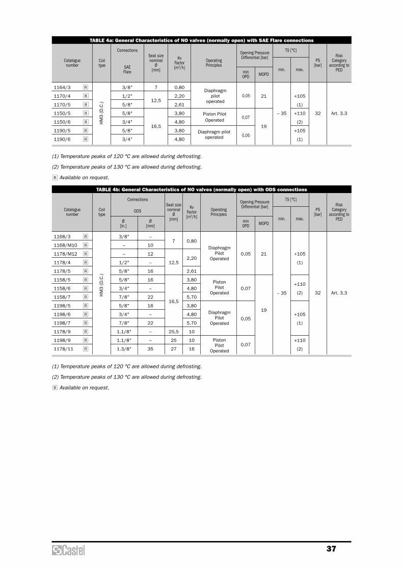
37
TABLE 4a: General Characteristics of NO valves (normally open) with SAE Flare connections
Cataloguenumber
0,05
0,07
0,05
SAEFlare
3/8"
1/2"
5/8"
5/8"
3/4"
5/8"
3/4”
7
12,5
16,5
0,80
2,20
2,61
3,80
4,80
3,80
4,80
21
19
– 35
+105
(1)
+110
(2)
+105
(1)
32 Art. 3.3
ConnectionsSeat sizenominal
Ø [mm]
Kv Factor[m3/h]
OperatingPrinciples
MOPD
Opening PressureDifferential [bar]
minOPD
min.
TS [°C]
max.
PS[bar]
RiskCategory
according to PED
Coil type
HM
3 (D
.C.)
1164/3
1170/4
1170/5
1150/5
1150/6
1190/5
1190/6 R
R
R
R
R
R
RDiaphragm
pilot operated
DiaphragmPilot
Operated
Piston Pilot
Operated
PistonPilot
Operated
DiaphragmPilot
Operated
Diaphragm pilot operated
Piston PilotOperated
(1) Temperature peaks of 120 °C are allowed during defrosting.
(2) Temperature peaks of 130 °C are allowed during defrosting.
Available on request.R
TABLE 4b: General Characteristics of NO valves (normally open) with ODS connections
Cataloguenumber
3/8"
–
–
1/2"
5/8"
5/8"
3/4"
7/8"
5/8"
3/4"
7/8"
1.1/8"
1.1/8"
1.3/8"
–
10
12
–
16
16
–
22
16
–
22
–
–
35
7
12,5
16,5
25,5
25
27
0,80
2,20
2,61
3,80
4,80
5,70
3,80
4,80
5,70
10
10
16
0,05
0,07
0,05
0,07
21
19
– 35
+105
(1)
+110
(2)
+105
(1)
+110
(2)
32 Art. 3.3
Ø[in.]
Ø[mm]
ODS
ConnectionsSeat sizenominal
Ø [mm]
Kv Factor[m3/h]
OperatingPrinciples
MOPD
Opening PressureDifferential [bar]
minOPD
min.
TS [°C]
max.
PS[bar]
RiskCategory
according to PED
Coiltype
HM
3 (D
.C.)
1168/3
1168/M10
1178/M12
1178/4
1178/5
1158/5
1158/6
1158/7
1198/5
1198/6
1198/7
1178/9
1198/9
1178/11 R
R
R
R
R
R
R
R
R
R
R
R
R
R
(1) Temperature peaks of 120 °C are allowed during defrosting.
(2) Temperature peaks of 130 °C are allowed during defrosting.
Available on request.R

38
Connectors and coils are not included in the boxes and have to be ordered separately.
SOLENOID VALVES FOR REFRIGERATING SYSTEMS
1164/31168/31168/M10
1170/41170/5
1178/M121178/41178/5
1150/51150/61190/51190/6
1158/51158/61158/71198/51198/61198/7
1178/9
1198/91178/11

39
TABLE 5: Dimensions and Weights of NO valves with 9120 coil
Cataloguenumber
Weight[g]
H1 H2 H3 L1 L2 Q
87
96
126
111
120
162
177
74,5
80
98
83
101
132
143
40
47
70
50
72
99
110
68
111
111
100
106
127
127
175
120
124
175
175
180
120
124
175
175
180
250
235
278
64
–
45
57
80
68
68
705
705
700
1015
1060
995
985
1080
1462
1792
1422
1612
1597
1340
1670
1300
1490
1475
2870
2355
3015
Dimensions [mm]
1164/3
1168/3
1168/M10
1170/4
1170/5
1178/M12
1178/4
1178/5
1150/5
1150/6
1158/5
1158/6
1158/7
1190/5
1190/6
1198/5
1198/6
1198/7
1178/9
1198/9
1178/11
TABLE 6: Refrigerant Flow Capacity of NO valves
Cataloguenumber
R134a R22 R407C R404A R134a R22 R407C R404A R134a R22 R407C R404A
Liquid Vapour Hot Gas
Refrigerant Flow Capacity [kW]
1164/3
1168/3
1168/M10
1170/4
1170/5
1178/M12
1178/4
1178/5
1150/5
1150/6
1158/5
1158/6
1158/7
1190/5
1190/6
1198/5
1198/6
1198/7
1178/9
1198/9
1178/11
13,5
37,1
44,0
37,1
44,0
64,0
80,9
64,0
80,9
96,0
64,0
80,9
64,0
80,9
96,0
168,5
168,5
269,6
14,4
39,6
47,0
39,6
47,0
68,4
86,4
68,4
86,4
102,6
68,4
86,4
68,4
86,4
102,6
180,0
180,0
288,0
15,0
41,2
48,9
41,2
48,9
71,2
90,0
71,2
90,0
106,8
71,2
90,0
71,2
90,0
106,8
187,4
187,4
299,8
9,5
26,2
31,1
26,2
31,1
45,2
57,1
45,2
57,1
67,8
45,2
57,1
45,2
57,1
67,8
119,0
119,0
190,4
1,73
4,75
5,64
4,75
5,64
8,2
10,4
8,2
10,4
12,3
8,2
10,4
8,2
10,4
12,3
21,6
21,6
34,6
2,16
5,94
7,05
5,94
7,05
10,3
13,0
10,3
13,0
15,4
10,3
13,0
10,3
13,0
15,4
27,0
27,0
43,2
2,14
5,90
6,99
5,90
6,99
10,2
12,9
10,2
12,9
15,3
10,2
12,9
10,2
12,9
15,3
26,8
26,8
42,9
1,81
4,97
5,90
4,97
5,90
8,6
10,8
8,6
10,8
12,9
8,6
10,8
8,6
10,8
12,9
22,6
22,6
36,2
6,8
18,7
22,2
18,7
22,2
32,3
40,8
32,3
40,8
48,5
32,3
40,8
32,3
40,8
48,5
85,0
85,0
136,0
9,4
25,7
30,5
25,7
30,5
44,5
56,2
44,5
56,2
66,7
44,5
56,2
44,5
56,2
66,7
117,0
117,0
187,2
9,3
25,6
30,3
25,6
30,3
44,2
55,8
44,2
55,8
66,2
44,2
55,8
44,2
55,8
66,2
116,2
116,2
185,9
8,0
22,0
26,1
22,0
26,1
38,0
48,0
38,0
48,0
57,0
38,0
48,0
38,0
48,0
57,0
100,0
100,0
160,0
Refrigerant flow capacity referred to the following operating conditions: Particularly for hot gas:– Evaporating temperatre: +4 °C – Suction temperature: +18 °C– Condensing temperature: +38 °C – Pressure drop: 1 bar– Pressure drop: 0,15 bar
40
Protection against electric contacts is class I forall the coils. Therefore, for safety purposes,coils must be effectively connected to anearthing system. Rubber gaskets on the upperand lower ends of coil ensure moistureprotection of winding. Coils HM2 and HM3 maybe joined to all connectors produced by Castelexcept type 9155/R01; protection degreeguaranteed by this system, coil (HM2, HM3) +connector, is IP65 according to EN 60529.Coils HM4 must be preferably used withconnector type 9155/R01; protection degreeguaranteed by this other system, coil HM4 +connector 9155/R01, is IP65/IP68 accordingto EN 60529. Coils HM4 can be used withconnectors series 9150 and 9900 too;protection degree guaranteed by this system isIP65.Either the terminals of coils series HM2 andHM3 or the ones of coils series HM4 consist oftwo Faston line connections plus one Fastonearthing connection. Coil type CM2 has a pre-assembled cable (length 1 meter).The coils are designed for continuous use. Thesolid construction of these coils is suitable forheavy-duty applications in refrigerant systems.The maximum ambient temperature for all coilsis 50 °C.
ELECRIC TYPE APPROVAL
Coils series 9100, 220/230 VAC and 240 VACsupply, are approved by the german registrationbody VDE. Coils series 9105 are approved by Underwriterslaboratories Inc. of the United States.Coils series 9100, 9110 and 9160, 110 VAC,220/230 Vac and 240 VAC supply, and coilsseries 9120, 220/230 VAC supply, aremanufactured according to low Voltage (LV)Directive 2006/95/EC. Coils series 9100,9110, 9120 and 9160 are manufacturedaccording to Electromagnetic Compatibility(EMC) Directive 2004/108/EC.
APPLICATION
For the normally closed solenoid valves,previously shown in this Handbook, Castel putsthe following types of coils at disposal of itsown customers:– coils series HM2, only for A.C.
(catalogue numbers 9100 - 9105).– coils series CM2, only for A.C.
(catalogue number 9110);– coils series HM3,either for A.C. or for D.C.
(catalogue number 9120).– coils series HM4, only for A.C.
(catalogue number 9160).
For the normally open solenoid valves, alwaysshown in this Handbook, the customer’sselection must compulsorily apply to the coilsseries HM3 – D.C.For applications of the NO solenoid valves witha voltage supply of 220 VAC, Castel hasdesigned a specific coil at 220 V RAC (code9120/RD6) that must be used solely with the220 VAC connector/rectifier circuit (code9150/R45).
CONSTRUCTION
Coils HM2 (9100) are class H, whereas coilsCM2, HM3 and HM4 are class F, in compliancewith IEC 85 standard and their construction isin compliance with EN 60730-1 and EN 60730-2-8 standards. The windings are made withcopper wire, insulation class H 180 °C, incompliance with IEC 85 standard. The outercasing is provided with dielectric andwaterproof resins that assure a reinforcedinsulation making the coils suitable for allassemblies.Coils HM2 (9105) are class F, with UL approvedEIS (Electrical Insulation System), and theirconstruction is in compliance with UL 429Standards.
COILS

41
TABLE 1: General Characteristics of coils
CoilType
Degree of
protectionConnectionsFrequency
[Hz]
Voltagetollerance
[%]
Voltage[V]
Cataloguenumber
HM2
HM2
u Recognized
File number E243604
CM2
HM3
HM4
9100/RA2
9100/RA4
9100/RA6
9100/RA7
9100/RA8
9105/RA2
9105/RA4
9105/RA6
9105/RA7
9110/RA2
9110/RA4
9110/RA6
9110/RA7
9120/RA6
9120/RD1
9120/RD2
9120/RD4
9120/RD6
9160/RA2
9160/RA4
9160/RA6
9160/RA7
24 A.C.
110 A.C.
220/230 A.C.
240 A.C.
380 A.C.
24 A.C.
110/120 A.C.
220/230 A.C.
240 A.C.
24 A.C.
110 A.C.
220/230 A.C.
240 A.C.
220/230 A.C.
12 D.C.
24 D.C.
48 D.C.
220 RAC
24 A.C.
110 A.C.
220/230 A.C.
240 A.C.
+10 / -10
+6 / -10
+10 / -10
+10 / -10
+6 / -10
+10 / -10
+10 / -10
+6 / -10
+10 / -10
+6 / -10
+10 / -5
+10 / -10
+6 / -10
+10 / -10
50 / 60
60
50 / 60
50 / 60
–
50 / 60
Junction box
DIN 43650
junction box
DIN 43650
Three wire cable
Junction box
DIN 43650
Junction box DIN 43650 or
Connector9155/R01 (1)
IP65
EN 60529
(with
junction box)
IP65 EN 60529
(with junction box)
IP65
EN 60529
IP65
EN 60529
(With
junction box)
IP65 EN 60529(with junction box)
IP65/IP68EN 60529
(with connector)
(1) Coil HM4 can also be coupled to connectors series 9150 and 9900, achieving a degree of protection IP65, the“versatile” degree of protection ( IP65/IP68) is achieved coupling coil HM4 with four screws connector 9155/R01
CM2HM2
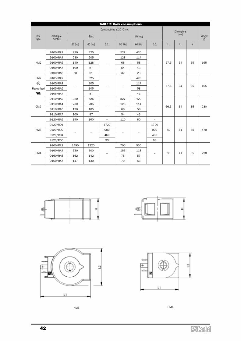
42
TABLE 2: Coils consumptions
Cataloguenumber
CoilType
50 [Hz]
Consumptions at 20 °C [mA]Dimensions
[mm]Weight
[g]
60 [Hz] D.C. 50 [Hz] 60 [Hz] D.C.
Start Working
9100/RA2
9100/RA4
9100/RA6
9100/RA7
9100/RA8
9105/RA2
9105/RA4
9105/RA6
9105/RA7
9110/RA2
9110/RA4
9110/RA6
9110/RA7
9120/RA6
9120/RD1
9120/RD2
9120/RD4
9120/RD6
9160/RA2
9160/RA4
9160/RA6
9160/RA7
HM2
HM2
uRecognized
CM2
HM3
HM4
920
230
140
100
58
–
920
230
120
100
190
–
1490
330
162
147
825
205
128
87
51
825
205
105
87
825
205
105
87
160
–
1320
300
142
130
_
–
–
–
1720
900
460
93
–
527
128
68
54
32
–
527
128
68
54
110
–
700
156
76
70
420
114
58
43
23
420
114
58
43
420
114
58
43
80
–
530
118
57
53
_
–
–
–
1720
900
460
93
–
L1 L2 H
57,5
57,5
66,5
82
63
34
34
34
61
41
35
35
35
35
35
165
165
230
470
220
HM3 HM4

43
with an external diameter of 6 ÷ 9 mm and isprovided with a self-locking device. Cables sized3 x 0,75 mm2 are to be preferred for this junctionbox too.The junction box type 9155/R01 offers aprotection degree IP65/IP68 against dust andwater, according to EN 60529, when correctlyinstalled with the proper gaskets, which aresupplied as standard.The junction box 9150/R45 is equipped with afull-wave bridge rectifier plus VDR for protection.The VDR device, Voltage e-Dependent-Resistor, isa special type of resistor, placed in parallel to thecoil; its purpose is to protect the diodes and thecoil from any excessive voltage generated withinthe ac supply circuit.
WARNING: the junction box 9150/R45 must besolely used with coils 9120/RD6 (220 VRAC).The wrong use of these junction boxes withother types of Castel coils takes quickly to thedestruction of the coil.
The junction boxes 9150, DIN 43650standardized, represent an effective system forthe connection of the coil to the supply circuit,thus ensuring safety also in the presence ofmoisture.These junction boxes, according to assemblyrequirements, allow choosing the position of outercasing compared to inner terminal block. Theclamping screw of casing may be PG9 or PG11,which are respectively suitable for cables with anexternal diameter of 6 ÷ 8 or 8 ÷ 10 mm. Cables sized 3 x 0,75 mm2 are to be preferred.The junction box type 9900 is available withcabled core of different length. In this case,it is not possible to change the position of casingcompared to terminal block.Both the two types offer a protection degree IP65against dust and water, according to EN 60529, when correctly installed with theproper gaskets, which are supplied as standard.Castel has developed a specific junction box, type9155/R01, suitable for use on those refrigeratingsystems working in heavy duty environments, forexample:– exposition to the atmospheric conditions;– rooms with high moisture degree;– cyclic condensing / evaporating on the valve;– cyclic icing / defrosting on the valve.This junction box, according to assemblyrequirements, allows choosing the side position ofouter casing compared to inner terminal block; butit is not possible to point the cable upwards. Thegland nut of casing is suitable to receive cables
CONNECTORS
TABLE 3: General Characteristics of connectors
Cataloguenumber
Nominal
Supply Voltage[V]
Maximum
PgCable length
[m]
Cablethickness
[mm2]Standard Degree
of protectionClass
of insulation
9150/R01
9150/R02
9150/R45
9155/R01
9900/X66
9900/X84
9900/X73
9900/X55
9900/X54
R
–
220 A.C.
–
–
–
250 A.C.
–
–
9
11
–
–
–
1
1,5
2
3
5
–
3 x 0,75
DIN
43650
–
DIN
43650
IP65
EN 60529
IP65/IP68
EN 60529
IP65
EN 60529
Group C VDE
0110-1
/ 89
Available on request.R

44
APPLICATIONS
The solenoid valves, shown in this chapter, areclassified “Pressure accessories” in the senseof the Pressure Equipment Directive 97/23/EC,Article 1, Section 2.1.4 and are subject ofArticle 3, Section 1.3 of the same Directive.They are designed for the applications specifiedin Table 1 where the different fluids areindicated with the following symbols, accordingto an already established code:– W = Water;– L = Air;– B = Secondary coolants (solutions of glycol
and water);– O = Light oils (gas oil).In short these valves may be used:– with fluids in the gaseous state proper to the
Group II (as defined in Article 9, Section 2.2of Directive 97/23/EC and referred to inDirective 67/548/EEC);
– with fluids in the liquid state proper to theGroup I (as defined in Article 9, Section 2.1of Directive 97/23/EC and referred to inDirective 67/548/EEC).
SOLENOID VALVES FOR DIFFERENT FLUIDS
APPLICATION
Castel supplies to its customers the permanentmagnet code 9900/X91 for the normally closedsolenoid valves, shown in this chapter.This product can be used during brazing of thevalve copper connections to the plant pipes;slipping it on the armature, instead of the coil, itallows the protective gas (nitrogen) flowing andavoids any damage to the plunger gasket and tothe diaphragm.
CONSTRUCTION
The main parts of the permanent magnet code9900/X91 are made with the following materials:– three rings of anisotropic ferrite;– anodized aluminum for the body.
PERMANENT MAGNET
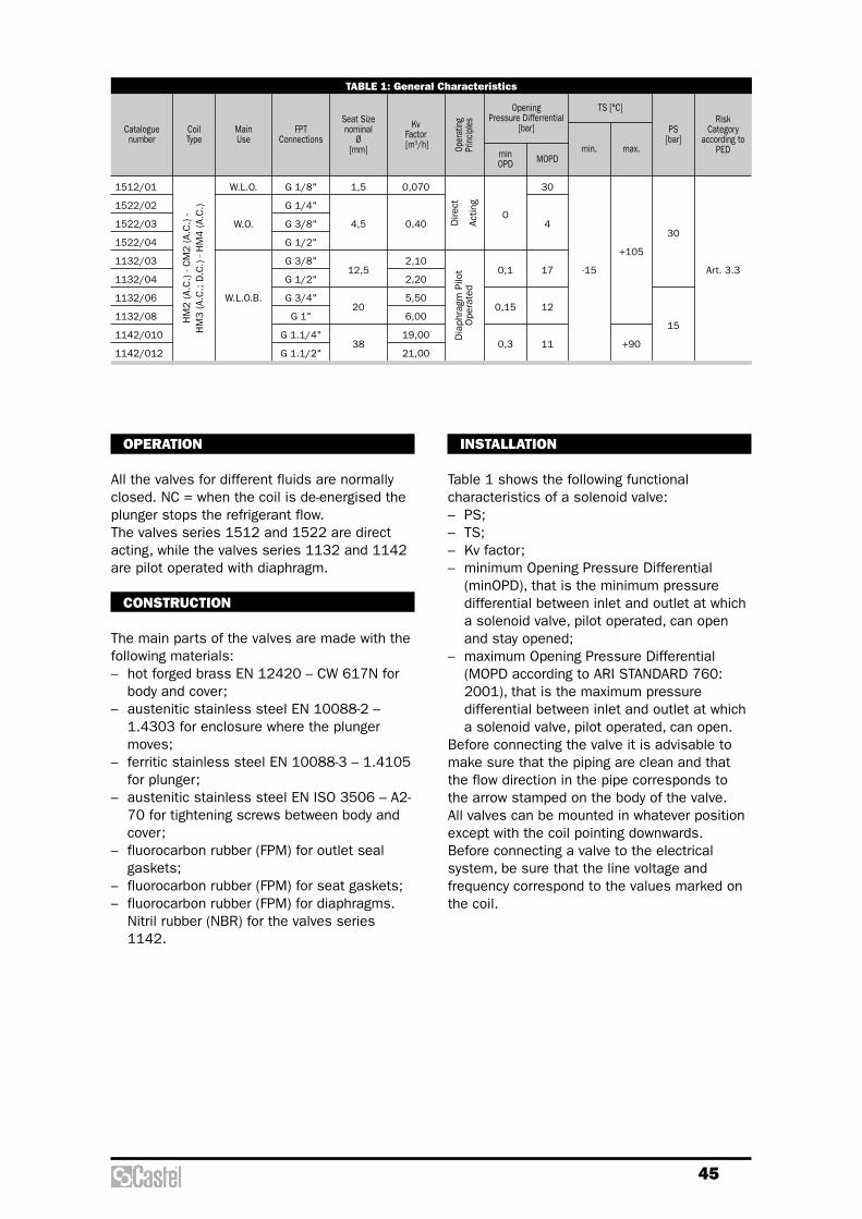
45
OPERATION
All the valves for different fluids are normallyclosed. NC = when the coil is de-energised theplunger stops the refrigerant flow.The valves series 1512 and 1522 are directacting, while the valves series 1132 and 1142are pilot operated with diaphragm.
CONSTRUCTION
The main parts of the valves are made with thefollowing materials:– hot forged brass EN 12420 – CW 617N for
body and cover;– austenitic stainless steel EN 10088-2 –
1.4303 for enclosure where the plungermoves;
– ferritic stainless steel EN 10088-3 – 1.4105for plunger;
– austenitic stainless steel EN ISO 3506 – A2-70 for tightening screws between body andcover;
– fluorocarbon rubber (FPM) for outlet sealgaskets;
– fluorocarbon rubber (FPM) for seat gaskets;– fluorocarbon rubber (FPM) for diaphragms.
Nitril rubber (NBR) for the valves series1142.
TABLE 1: General Characteristics
Cataloguenumber
1,5
4,5
12,5
20
38
G 1/8"
G 1/4"
G 3/8"
G 1/2"
G 3/8"
G 1/2"
G 3/4"
G 1"
G 1.1/4"
G 1.1/2"
W.L.O.
W.O.
W.L.O.B.
0,070
0,40
2,10
2,20
5,50
6,00
19,00
21,00
0
0,1
0,15
0,3
30
4
17
12
11
-15
+105
+90
30
15
Art. 3.3
FPTConnections
Main Use
Seat Sizenominal
Ø[mm]
KvFactor[m3/h] Op
erat
ing
Prin
ciple
s
MOPD
Opening Pressure Differrential
[bar]
minOPD
min.
TS [°C]
max.
PS[bar]
RiskCategory
according to PED
CoilType
HM
2 (A.
C.) -
CM
2 (A.
C.) -
HM
3 (A.
C.; D
.C.) -
HM
4 (A.
C.)
Dire
ct
Actin
gD
iaph
ragm
Pilo
tO
pera
ted
1512/01
1522/02
1522/03
1522/04
1132/03
1132/04
1132/06
1132/08
1142/010
1142/012
INSTALLATION
Table 1 shows the following functionalcharacteristics of a solenoid valve:– PS;– TS;– Kv factor;– minimum Opening Pressure Differential
(minOPD), that is the minimum pressuredifferential between inlet and outlet at whicha solenoid valve, pilot operated, can openand stay opened;
– maximum Opening Pressure Differential(MOPD according to ARI STANDARD 760:2001), that is the maximum pressuredifferential between inlet and outlet at whicha solenoid valve, pilot operated, can open.
Before connecting the valve it is advisable tomake sure that the piping are clean and thatthe flow direction in the pipe corresponds tothe arrow stamped on the body of the valve. All valves can be mounted in whatever positionexcept with the coil pointing downwards. Before connecting a valve to the electricalsystem, be sure that the line voltage andfrequency correspond to the values marked onthe coil.
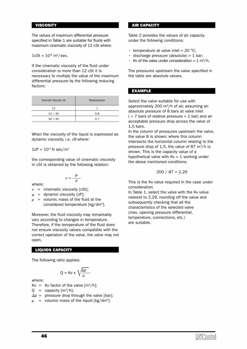
46
AIR CAPACITY
Table 2 provides the values of air capacityunder the following conditions:
• temperature at valve inlet = 20 °C;• discharge pressure (absolute) = 1 bar;• Kv of the valve under consideration = 1 m3/h.
The pressures upstream the valve specified inthe table are absolute values.
EXAMPLE
Select the valve suitable for use withapproximately 200 m3/h of air, assuming anabsolute pressure of 8 bars at valve inlet ( = 7 bars of relative pressure + 1 bar) and anacceptable pressure drop across the valve of1,5 bars. In the column of pressures upstream the valve,the value 8 is shown; where this columnintersects the horizontal column relating to thepressure drop of 1,5, the value of 87 m3/h isshown. This is the capacity value of ahypothetical valve with Kv = 1 working underthe above mentioned conditions.
200 / 87 = 2,29
This is the Kv value required in the case underconsideration. In Table 1, select the valve with the Kv valuenearest to 2,29, rounding off the value andsubsequently checking that all thecharacteristics of the selected valve (max. opening pressure differential,temperature, connections, etc.) are suitable.
When the viscosity of the liquid is expressed asdynamic viscosity, i.e. cP, where:
1cP = 10-3 N sec/m2
the corresponding value of cinematic viscosityin cSt is obtained by the following relation:
mn = ——r
where:n = cinematic viscosity [cSt];m = dynamic viscosity [cP];r = volumic mass of the fluid at the
considered temperature [kg/dm3].
Moreover, the fluid viscosity may remarkablyvary according to changes in temperature.Therefore, if the temperature of the fluid doesnot ensure viscosity values compatible with thecorrect operation of the valve, the valve may notopen.
LIQUIDS CAPACITY
The following ratio applies:
DpQ = Kv x =++——
rwhere:Kv = Kv factor of the valve [m3/h];Q = capacity [m3/h];Dp = pressure drop through the valve [bar];r = volumic mass of the liquid [kg/dm3].
Cinematic Viscosity cSt Reducing factor
12
12 ÷ 30
30 ÷ 45
1
0,8
0,7
VISCOSITY
The values of maximum differential pressurespecified in Table 1 are suitable for fluids withmaximum cinematic viscosity of 12 cSt where:
1cSt = 10-6 m2/sec.
If the cinematic viscosity of the fluid underconsideration is more than 12 cSt it isnecessary to multiply the value of the maximumdifferential pressure by the following reducingfactors:

47
TABLE 2 - Air Capacity (Kv = 1)
Pressuredrop[bar]
18 17 16 15 14 13 12 11 10 9 8 7 6 5 4 3 2 1,5 1,3 1,2 1,1 1,05 1,03 1,015
Capacity [m3/h] (1)
Inlet pressure (absolute) [bar]
0,0025
0,005
0,010
0,015
0,025
0,05
0,1
0,15
0,25
0,5 82,0 80,0 77,0 74,0 72,0 69,5 66,6 63,7 60,6 57,3 54,0
1 115,0 111,0 108,0 104,0 100,0 96,0 92,0 88,0 83,0 78,6 73,5
1,5 138,0 134,0 130,0 125,0 120,0 115,5 110,3 105,0 99,3 93,0 87,0
2 157,0 152,0 147,0 142,0 136,0 130,0 124,0 118,0 111,0 96,0 96,0
2,5 173,0 167,5 161,5 155,5 149,0 142,5 135,5 128,0 120,4 112,0 103,0
3 186,0 180,0 174,0 167,0 160,0 152,0 144,5 136,0 127,0 118,0 108,0
3,5 198,0 191,0 184,0 176,5 168,6 160,3 151,7 142,5 132,6 122,0 110,0
4 208,0 200,0 193,0 184,0 176,0 167,0 157,0 147,0 136,0 124,0 111,0
4,5 216,0 208,6 200,0 191,0 182,0 172,0 161,5 150,4 138,0 125,0
5 224,0 215,0 206,0 195,5 186,0 176,0 164,5 152,3 139,0
5,5 230,0 221,0 211,0 201,0 190,0 178,6 166,3 152,9
6 236,0 226,0 215,0 204,0 192,7 180,0 166,8
6,5 240,0 230,0 218,0 206,7 194,0 180,7
7 244,0 233,0 220,0 208,0 194,7
7,5 246,0 234,0 222,0 208,5
8 249,0 236,0 222,5
8,5 250,0 236,5
9 250,5
1,46 1,42 1,40 1,35
2,2 2,10 2,00 1,95 1,90
3,0 3,0 3,00 2,85 2,80 2,75
4,2 3,9 3,7 3,55 3,45 3,40 3,35
6,2 5,4 5,0 4,8 4,56 4,45 4,40
10,7 8,7 7,5 6,9 6,6 6,40 6,20
17,4 15,0 12,2 10,2 9,6 9,2 8,8
23,8 21,2 18,3 14,6 12,5 11,5 11,0
33,4 30,4 27,0 23,2 18,5 15,6 13,9
50,0 46,0 41,7 36,8 31,0 24,3 19,6
68,0 62,0 55,6 48,0 39,3 27,8
80,0 72,0 63,7 53,8 41,7
88,0 78,0 68,0 55,6
89,5 82,0 69,5
96,0 83,0
97,0
(1) The table provides air capacity values in m3/h under the following conditions:– temperature at value inlet: + 20 °C– pressure at outlet (absolute): 1 bar– Kv of the solenoid valve: 1 m3/h
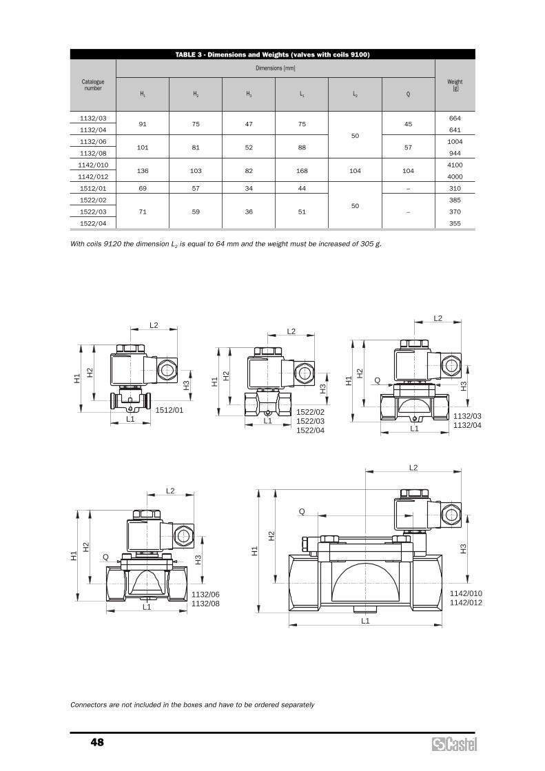
48
With coils 9120 the dimension L2 is equal to 64 mm and the weight must be increased of 305 g.
TABLE 3 - Dimensions and Weights (valves with coils 9100)
Cataloguenumber
Weight[g]
H1 H2 H3 L1 L2 Q
91
101
136
69
71
75
81
103
57
59
47
52
82
34
36
75
88
168
44
51
50
104
50
45
57
104
–
–
664
641
1004
944
4100
4000
310
385
370
355
Dimensions [mm]
1132/03
1132/04
1132/06
1132/08
1142/010
1142/012
1512/01
1522/02
1522/03
1522/04
Connectors are not included in the boxes and have to be ordered separately
H2
H1
L1
L2
H3
H2
L1
H1
H3
L2
1132/031132/04
Q
L1
H2
H1
Q
H3
L2
1142/0101142/012
1132/061132/08
H2
H3H
1
L1
L2
H2
H3H
1
L1
L2
1512/011522/031522/04
1522/02
Q

Safetydevices

50
atmosphere. For this reason, during relief, agas leak occurs through this orifice.Utilized material: EN 12420-CW617N brass.
Disc: obtained through bar machining andequipped with gasket, it ensures the requiredsealing degree on the valve seat. The gasket ismade in P.T.F.E. (Polytetrafluorethylene), amaterial that, during valve estimated servicelife, maintains a good strength and does notcause the disc to stick on the seat. The disc isproperly guided in the body and the guideaction can never fail; there are no glands orretaining rings that hamper the movementthereof.Utilized material: EN 12164-CW614N brass.
Spring: it opposes the pressure and the fluiddynamic actions and always ensures valve re-closing after pressure relief. The spring coils,when the disc has reached the liftcorresponding to the state of relief at full flowrate, are spaced apart by at least half the wirediameter and, in any case, by not less than 2mm. The disc is equipped with a mechanic lockand when it attains it, the spring set does notexceed 85% of the total set.Utilized material: DIN 17223-1 steel for springs.
Setting system: hexagonal head, threadedring nut to be screwed inside the body top bycompressing the spring below. On settingcompletion, the position attained by the ring nutis maintained unchanged laying, in the threadedcoupling, a bonding agent with high mechanicstrength and low viscosity features to makepenetration thereof easier. The setting systemis protected against subsequent unauthorizedinterventions by means of a cap nut that isscrewed outside the body and is sealed withCastel lead to it.
GENERAL DESCRIPTION
Valves series 3030 are safety devicesaccording to the definition given in Article 1,Point 2.1.3, 2nd dash of 97/23/EC Directiveand are the subject of Article 3, Point 1.4 ofaforesaid Directive.The valves above mentioned are standard type,unbalanced, direct-loaded safety valves. Valveopening is produced by the thrust the fluidunder pressure exerts on the disc, when saidthrust exceeds, under setting conditions, theopposing force of the spring acting on the disc.
Valves are identified by means of:– a model number formed of an
alphanumerical coding that includes:– in the first part the family identification
(e.g. 3030/44C);– in the second part the setting pressure,
expressed in bars, multiplied by 10 (e.g.140);
– an alphanumerical serial number.
CONSTRUCTION
Body: squared, obtained through die forgingand subsequent machining. It houses thefollowing elements:– the nozzle with flat sealing seat;– the disc guide;– the setting spring holder;– the threaded seat of the setting adjusting
ring nut.
In the body, above the disc guide, a smallpressure relief hole is provided through whichthe spring holder is put into contact with the
SAFETY VALVES 3030
TABLE 1: General Characteristics of valves 3030
1/2" NPT
3/4" G
12
113
4,1
0,90
3/4" NPT
3/4" G
12
113
4,1
0,90
1" NPT
1.1/4" G
19,5
298
6,8
0,83
Catalogue number 3030/44C 3030/66C 3030/88C
Connections
Flow Diameter [mm]
Flow Section [mm2]
Lift [mm]
Discharge Coefficient “Kd”
PS [bar]
TS [°C]
Set Pressure Range [bar]
Overpressure
Blowdown
Risk category according to PED
55
- 50 / + 150
8 / 50
5% of set pressure
15% of set pressure
IV
Inlet male
Outlet male

51
L
H2H1
D
H3
Ch
safety devices such as safety valves. Suchdevices shall prevent pressure frompermanently exceeding the max allowablepressure PS of the equipment they protect. Inany case, a short pressure peak limited to 10%of admissible maximum pressure is permitted.As to the selection and sizing of the suitableprotection device, users shall refer to thespecific sector or product standards.EN 378-2: 2008 Standard “Refrigeratingsystems and heat pumps – safety andenvironmental requirements – Part 2: Design,construction, testing, marking anddocumentation”, harmonized with 97/23/ECDirective, provides a general outline of theprotection devices to be adopted in refrigeratingsystems and their features (par 6.2.5). It alsoindicates the criteria for the selection of thedevice suitable to the type and sizes of thesystem component to be protected (par. 6.2.6).EN 13136: 2001/A1: 2005 Standard“Refrigerating systems and heat pumps –Pressure relief devices and their associatedpiping – Methods for calculation” highlights thepossible causes of overpressure in a systemand makes available to users the instrumentsfor pressure relief device sizing, among whichthe safety valves.
SCOPE
Use: protection against possible overpressuresof the apparatuses listed below, with regard tothe operating conditions for which they havebeen designed:– refrigerating system and heat pump
components, for instance: condensers, liquidreceivers, evaporators, liquid accumulators,positive displacement compressor discharge,heat exchangers, oil separators, piping(reference: EN 378-2: 2008);
– simple pressure vessels(reference: 87/404/ EEC Directive).
Fluids: the valves can be used with:– refrigerant fluids, in the physical state of gas
or vapour, belonging to Group II according tothe definitions of 97/23/EC Directive, Article9, Point 2.2 (with reference to 67/548/EECDirective of June 27th, 1967);
– air and nitrogen (reference: 87/404/EECDirective).
MARKING
In conformity with the provisions of Article 15 of97/23/EC Directive, the EC marking and theidentification number of the notified bodyinvolved in the production control phase arereported on the valve body.Still on the body, the following information isindicated:– manufacturer’s mark, address and
manufacture country;– valve model;– flow section;– Kd discharge coefficient;– indication of flow direction;– max allowable pressure;– allowable temperature range;– set pressure;– production date;– serial number.
VALVE SELECTION
97/23/EC Directive requires that pressureequipment, in which permissible limits arereasonably likely to be exceeded, shall be fittedwith suitable protection devices, for instance
TABLE 2: Dimensions and Weights of valves 3030
Cataloguenumber
Weight[g]
3030
Ø D L Ch H1 H2 H3
38
38
50
38
38
56
28
28
40
44
44
58
115
115
158
159
159
216
780
780
1960
Dimensions [mm]
3030/44C
3030/66C
3030/88C

52
for this calculation the value of k shall be asmeasured at 25 °C. (Section 7.2.3, StandardEN 13136: 2001/A1:2005).Values of k and calculated values of C for somerefrigerants are given in table A.1 of theaforesaid standard.Following we show the values of k and C for themore useful refrigerants.
SIZING OF SAFETY VALVES DESIGNED TO DISCHARGE GAS OR VAPOUR ATCRITICAL FLOW (Ref. EN 13136: 2001/A1: 2005)
Critical flow occurs when the backpressure pb
(the pressure existing immediately at the outletof a safety valve) is below or equal to thecritical pressure:
[bar abs]
with:– po = actual relieving pressure, upstream the
safety valve; it’s equal to the set pressureplus overpressure. That is a pressureincrease over set pressure at which the dischas its total lift. [bar abs];
– k = isentropic exponent of gas or vapour,based on the actual flowing conditions at thesafety valve inlet.
If k is unknown or anyway difficult to establishit’s possible to suppose:
[bar abs]
A safety valve, which discharges toatmosphere, works in critical flow.
The safety valves designed to discharge gas orvapour at critical flow must be sized as follow:
[mm2]
with:– Ac = minimum flow area of safety valve
[mm2];– Qmd = minimum required discharge capacity,
of refrigerant, of safety valve [kg/h];– Kd = certified coefficient of discharge;– po = actual relieving pressure, upstream the
safety valve, see definition above [bar abs];
– vo = specific volume of gas or vapour atrelieving conditions po e To meaning with To
fluid temperature at valve inlet, settled bythe user or by the designer [m3/kg];
– C = function of isentropic coefficient kcalculated from:
C kk
k
k= × ×
+
+( )−( )
3 9482
1
1
1,
AQ
C Kvpc
md
d
o
o
= ×× ×
×3 4690 9
,,
p pcritical o= ×0 5,
p pkb o
kk
≤+
−⎛⎝⎜
⎞⎠⎟2
1
1
Calculation of minimum required dischargecapacity of safety valve is closely linked tothe type of system where the valve isinstalled, with the causes that may arousethe opening of safety valve, i.e.:
– external heat sources. The minimumrequired discharge capacity shall bedetermined by the following:
[kg/h]
with:– � = density of heat flow rate, it’s assumed
to be 10 [kW/m2];– Asurf = external surface area of the vessel
[m2];– hvap = heat of vaporization of liquid at po
[kJ/kg];
– internal heat sources. The minimum requireddischarge capacity shall be determined bythe following:
[kg/h]
withQh = rate of heat production [kW].
– Excessive pressure caused by compressors.The minimum required discharge capacityshall be determined by the following:
[kg/h]Q V nmd v= × × × ×60 10ρ η
hmdh
vap
=×3600
QA
hmdsurf
vap
=× ×3600 ϕ
RefrigerantIsentropiccoefficient
k
Functionof Isentropiccoefficient
C
R22
R134a
R404A
R407C
R410A
R507
1,17
1,12
1,12
1,14
1,17
1,10
2,54
2,50
2,50
2,51
2,54
2,48

53
– ηv = volumetric efficiency estimated atsuction pressure and discharge pressureequivalent to the safety valve setting.
with:– V = theoretical displacement of
compressor [m3]– n = rotational frequency of compressor
[min –1]– ρ10 = vapour density at refrigerant
saturation pressure / dew point at 10 °C [kg/m3]
These conditions, settled in any case by thedesigner, are considered the most unfavorablefor the safety valve in consequence offunctional defects as:– move mistake;– non-working of automatic safety devices, set
to operate before safety valve.
It shall be excluded:– closeness the refrigerating system, the
presence of flammable substances in solarge quantities to be able to feed a fire.;
– inside the vessel, the presence of a heartsource.
Calculation of minimum discharge capacityPrudentially leaving the vapour overheating atthe outlet of the liquid cooler out of account,the volumetric efficiency of compressor is:
and so the minimum required dischargecapacity:
= 60x0,00224x1450x26,34x0,83=4260 [kg/h]
with ρ10 = 26,34 [kg/m3], vapour density ofR407C at saturation pressure / dew point at10 °C.
Q V nmd v= × × × × =60 10ρ η
ηvdisch e
suction
p
p= − = − =1 0 04 1 0 04
27 256 33
0 83, ,,
,,arg
System descriptionCompact refrigerating system designed to makerefrigerated water and consisting of:– open type reciprocating compressor;– water-cooled, shell-and-tube horizontally
condenser with lower section of shell usedas receiver;
– shell-and-tube horizontally liquid cooler fedwith a thermostatic valve;
– refrigerant fluid R407C.
Compressor data– Bore 82,5 mm– Stroke 69,8 mm– Cylinder number 6– Rotational frequency 1450 rpm– Clearance 4%The theoretical displacement of compressor is:
[m3]
Maximum allowable pressure of the condenser,refrigerant side: PS = 25 bar.
Set pressure of the safety valve installed onthe upper shell section of condenser: pset = 25 bar
Actual relieving pressure of safety valve,choosing one valve type 3030 with anoverpressure of 5%:
[bar abs]
Working conditions of compressorcorresponding to the relieving of safety valve:Condensing temperature:
+ 64 °C (27,25 bar abs)Evaporating temperature:
+ 10 °C (6,33 bar abs)
p pset0 15
1001 27 25= × +
+ = ,
V = × × × =π4
0 0825 0 0698 6 0 002242, , ,
EXAMPLE OF CALCULATION OF MINIMUM REQUIRED DISCHARGE CAPACITY Qmd AND SIZING OFTHE SAFETY VALVE FOR THE HIGH PRESSURE SIDE OF A REFRIGERATING SYSTEM

54
Sizing of minimum flow area of the safety valve
[mm2]
with:– C = 2,51, corresponding to isentropic
exponent k for R407C equal to 1,14,according to table A1 of standard EN13136:2001/A1:2005;
– Kd = 0,83, certified coefficient of dischargefor safety valve 3030/88;
– vo = 0,0104 [m3/kg], specific volume ofoverheating vapour upstream the safety valveduring relieving.This value is referred to the followingoperating conditions, upstream the safetyvalve:– pressure po = 27,25 [bar abs];– temperature To = 100 [°C] (precautionary
temperature, settled in any case by thedesigner).
Conclusion: the selected safety valve is themodel 3030/88 with the followingcharacteristics:– certified coefficient of discharge, Kd = 0,83;– flow section, Ac = 298 [mm2];– set pressure, pset = 25 bar.
In case of single-screw compressor withinjection of pressurized oil, the theoreticaldisplacement is:
[m3]
with:– D = rotor diameter [m]– L = rotor length [m]
VD
Lc =×
×π 2
4
= ×× ×
× =3 4694260
2 51 0 9 0 830 010427 25
154,, , ,
,,
AQ
C Kvpc
md
d
o
o
= ×× ×
× =3 4690 9
,,

55
with:– A = flow area of safety valve [mm2];– Ain = inside area of inlet tube to valve [mm2];– Kdr = Kd x 0,9, derated coefficient of discharge;– C = function of isentropic coefficient k;– ξ = addition of pressure loss coefficients
ξn of any component and piping;The coefficients ξn are relevant to:– pipe elements loss, as connections and
bends;– valves loss;– loss along the pipe and are listed in EN 13136:2001/A1:2005Standard, Table A.4.
Example: assume to install, on the condenserof the previous example, a safety valve type3030/88, set to 25 bar, using a steel unionwith the following characteristics:– din = 28 [mm], inside diameter;– Ain = 616 [mm2], inside area;– L = 60 [mm], length;– flush connection to the shell of condenser,
with a broken edge.From table A.4 it’s possible to have these data:– ξ1 (inlet) = 0,25– ξ2 (length) = λ x L/ din = 0,02 x 60/28 = 0,043
with λ = 0,02 for steel tube– ξT = ξ1 + ξ2 = 0,25 + 0,043 = 0,293Between safety valve and union it’s installed ashut-off valve type 3033/88 (see page 59). Themain characteristics of this valve are:– dR = 20 [mm], inside diameter;– AR = 314 [mm2], inside area;– kv = 20 [m3/h], kv factor.Pressure loss coefficient ξR of shut-off valve isgiven by:
The total pressure loss coefficient is:ξT + ξR = 0,933
We remember the main characteristics of safetyvalve 3030/88 and of refrigerant fluid R407C:– A = 298 [mm2]– Kdr = 0,83 x 0,9 =0,747– C = 2,51
Pressure loss in the upstream line is:
Δpp
in
o
= × × ×⎡⎣⎢
⎤⎦⎥× =0 032
298616
2 51 0 747 0 933 0 02452
, , , , ,
ζR = × ⎡⎣⎢
⎤⎦⎥× =−2 592
31420
10 0 642
3, ,
VALVE INSTALLATIONAs far as the installation of safety relief valvesis concerned, the fundamental points listedbelow shall be taken into account:• safety valves shall be installed near an area
of the system where vapours or gases arepresent and there is no fluid turbulence; theposition shall be as upright as possible, withthe inlet connector turned downwards;
• vessels, joined together with piping rightlyselected by the manufacturer and withoutany stop valve between them, may beconsidered as only one vessel for theinstallation of a safety valve;
• the union between the valve and theequipment to be protected shall be as shortas possible. Furthermore, its passagesection shall not be narrower than the valveinlet section. In any case, EN 13136:2001/A1:2005 Standard states that thepressure loss between protected vessel andsafety valve, at discharge capacity, shall notexceed 3% of the setting value, including anyaccessory mounted on the upstream line;
• in selecting the safety valve location, it shallbe taken into account that valve operationinvolves the discharge of the refrigerant fluidunder pressure, sometimes even at hightemperature. Where the risk exists to causedirect injuries to the persons nearby, anexhaust conveying piping shall be provided,which shall be sized in such a way as not tocompromise valve operation. EN 13136: 2001/A1:2005 Standard statesthat this piping shall not generate, atdischarge capacity, a back pressureexceeding 10% of pressure po, for standardtype valves, unbalanced.
To calculate the pressure loss either in theupstream line (between vessel and safetyvalve) or in the downstream line (betweensafety valve and atmosphere) refer to EN 13136: 2001/A1:2005 Standard, Chapter7.4.
Pressure loss in the upstream lineCalculation of pressure loss is given by:
Δpp
AA
C Kin
o indr= × × ×
⎡
⎣⎢
⎤
⎦⎥ ×0 032
2
, ζ

56
Example: assume to install a discharge pipe onsafety valve type 3030/88 of the previousexample, using a steel tube nominal size 2”with the following characteristics:
- dout = 53 [mm] , inside diameter- Aout = 2206 [mm2] , inside area- L = 3000 [mm] , length- pipe bend 90° with bending radius R equal to
three times external diameter of tube
From table A.4 it’s possible to have these data:- ξ1 (bend) = 0,25- ξ2 (length) = λ x L/ din = 0,02 ξ 3000/53 = 1,13
with λ = 0,02 for steel tube- ξT = ξ1 + ξ2 = 0,25 + 1,13 = 1,38
Pressure loss in the downstream line is:
The obtained value is admissible because lowerthan the value of 0,10 forecast in EN13136:2001/A1:2005 Standard.
The obtained value is admissible because lowerthan the value of 0,03 forecast in EN 13136:2001/A1:2005 Standard.
Pressure loss in the downstream line
Calculation of pressure loss is given by:
with:- P1 = inlet pressure to downstream line
[bar ass]- P2 = outlet pressure to downstream line,
equal to atmospheric pressure [bar ass]- A = flow area of safety valve [mm2]- Aout = inside area of outlet tube to valve
[mm2]- Kdr = Kd x 0,9 , derated coefficient of
discharge- C = function of isentropic coefficient k- Po = actual relieving pressure, upstream the
valve [bar abs]- ξ = addition of pressure loss coefficients
ξn of pipingThe coefficients ξn are relevant to:- pipe elements loss, bends- loss along the pipe and are listed in EN 13136:2001//A1:2005Standard, Table A.4.
[bar]

57
SAFETY VALVES 3060
GENERAL DESCRIPTION
Valves series 3060 are safety devicesaccording to the definition given in Article 1,Point 2.1.3, 2nd dash of 97/23/EC Directiveand are the subject of Article 3, Point 1.4 ofaforesaid Directive.The valves above mentioned are standard type,unbalanced, direct-loaded safety valves. Valveopening is produced by the thrust the fluidunder pressure exerts on the disc, when saidthrust exceeds, under setting conditions, theopposing force of the spring acting on the disc.
Valves are identified by means of:– a model number formed of an
alphanumerical coding that includes:– in the first part the family identification
(e.g. 3060/45C);– in the second part the setting pressure,
expressed in bars, multiplied by 10 (e.g.140);
– an alphanumerical serial number.
CONSTRUCTION
Body: squared, obtained through die forgingand subsequent machining. It houses thefollowing elements:– the nozzle with flat sealing seat;– the disc guide;– the setting spring holder;– the threaded seat of the setting adjusting
ring nut.In the body, above the disc guide, a small
pressure relief duct is provided through whichthe spring holder is put into contact with theoutput connection. Utilized material: EN 12420-CW617N brass.
Disc: obtained through bar machining andequipped with gasket, it ensures the requiredsealing degree on the valve seat. The gasket ismade in P.T.F.E. (Polytetrafluorethylene), amaterial that, during valve estimated servicelife, maintains a good strength and does notcause the disc to stick on the seat. The disc isproperly guided in the body and the guideaction can never fail; there are no glands orretaining rings that hamper the movementthereof.Utilized material: EN 12164-CW614N brass.
Spring: it opposes the pressure and the fluiddynamic actions and always ensures valve re-closing after pressure relief.Utilized material: DIN 17223-1 steel for springs.
Setting system: hexagonal head, threadedring nut to be screwed inside the body top bycompressing the spring below. On settingcompletion, the position attained by the ring nutis maintained unchanged laying, in the threadedcoupling, a bonding agent with high mechanicstrength and low viscosity features to makepenetration thereof easier. The setting systemis protected against subsequent unauthorizedinterventions by means of a cap nut that ishoused into the brass body and is fixed in thisseat with an edge calking operation.
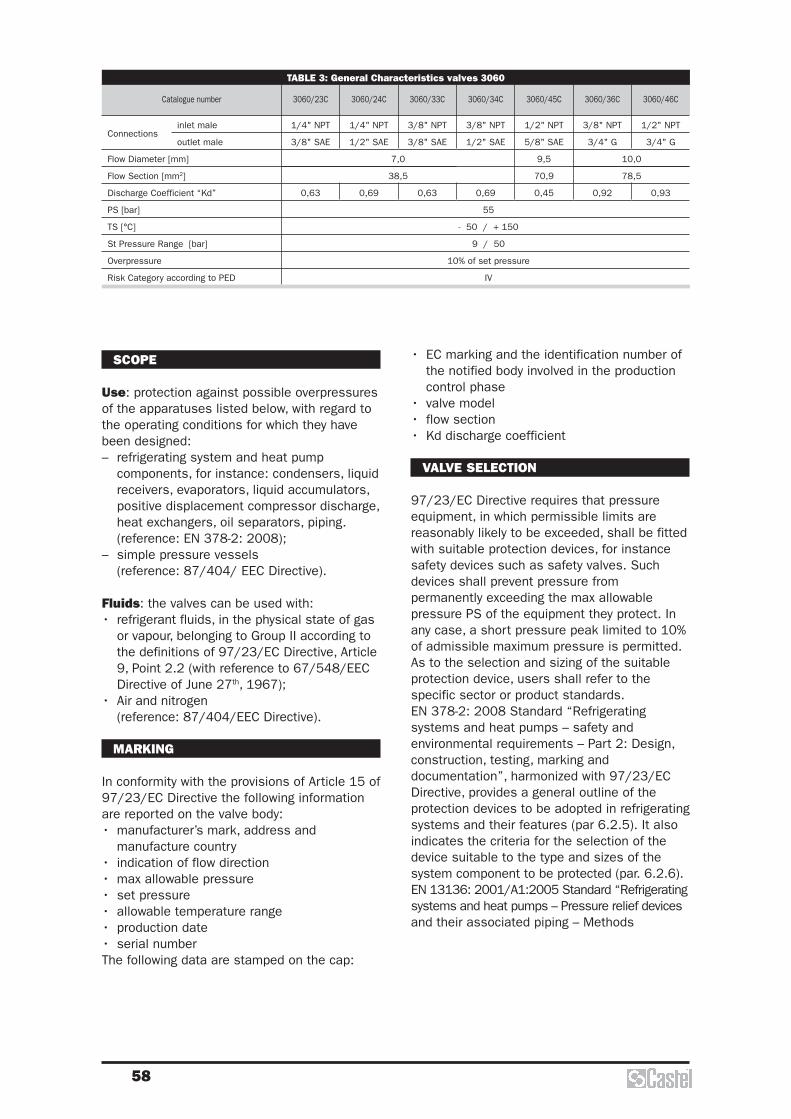
SCOPE
Use: protection against possible overpressuresof the apparatuses listed below, with regard tothe operating conditions for which they havebeen designed:– refrigerating system and heat pump
components, for instance: condensers, liquidreceivers, evaporators, liquid accumulators,positive displacement compressor discharge,heat exchangers, oil separators, piping.(reference: EN 378-2: 2008);
– simple pressure vessels(reference: 87/404/ EEC Directive).
Fluids: the valves can be used with:• refrigerant fluids, in the physical state of gas
or vapour, belonging to Group II according tothe definitions of 97/23/EC Directive, Article9, Point 2.2 (with reference to 67/548/EECDirective of June 27th, 1967);
• Air and nitrogen(reference: 87/404/EEC Directive).
MARKING
In conformity with the provisions of Article 15 of97/23/EC Directive the following informationare reported on the valve body:• manufacturer’s mark, address and
manufacture country• indication of flow direction• max allowable pressure• set pressure• allowable temperature range• production date• serial numberThe following data are stamped on the cap:
58
• EC marking and the identification number ofthe notified body involved in the productioncontrol phase
• valve model• flow section• Kd discharge coefficient
VALVE SELECTION
97/23/EC Directive requires that pressureequipment, in which permissible limits arereasonably likely to be exceeded, shall be fittedwith suitable protection devices, for instancesafety devices such as safety valves. Suchdevices shall prevent pressure frompermanently exceeding the max allowablepressure PS of the equipment they protect. Inany case, a short pressure peak limited to 10%of admissible maximum pressure is permitted.As to the selection and sizing of the suitableprotection device, users shall refer to thespecific sector or product standards.EN 378-2: 2008 Standard “Refrigeratingsystems and heat pumps – safety andenvironmental requirements – Part 2: Design,construction, testing, marking anddocumentation”, harmonized with 97/23/ECDirective, provides a general outline of theprotection devices to be adopted in refrigeratingsystems and their features (par 6.2.5). It alsoindicates the criteria for the selection of thedevice suitable to the type and sizes of thesystem component to be protected (par. 6.2.6).EN 13136: 2001/A1:2005 Standard “Refrigeratingsystems and heat pumps – Pressure relief devicesand their associated piping – Methods
TABLE 3: General Characteristics valves 3060
1/4" NPT
3/8" SAE
0,63
7,0
38,5
10,0
78,5
1/4" NPT
1/2" SAE
0,69
3/8" NPT
3/8" SAE
0,63
3/8" NPT
1/2" SAE
0,69
1/2" NPT
5/8" SAE
9,5
70,9
0,45
3/8" NPT
3/4" G
0,92
1/2" NPT
3/4" G
0,93
Catalogue number 3060/23C 3060/24C 3060/33C 3060/34C 3060/45C 3060/36C 3060/46C
Connections
Flow Diameter [mm]
Flow Section [mm2]
Discharge Coefficient “Kd”
PS [bar]
TS [°C]
St Pressure Range [bar]
Overpressure
Risk Category according to PED
55
- 50 / + 150
9 / 50
10% of set pressure
IV
inlet male
outlet male

59
Ch
H1
L
H2H3
DØfor calculation” highlights the possible causes ofoverpressure in a system and makes availableto users the instruments for pressure reliefdevice sizing, among which the safety valves.For sizing and installation of safety valvesseries 3060 see the previous chapter of safetyvalves series 3030.
TABLE 4: Dimensions and Weights of valves 3060
Cataloguenumber
Weight[g]
3060
Ø D L Ch H1 H2 H3
21,5
21,5
21,5
21,5
24,5
30
30
35
35
35
35
39,0
40
40
20
20
20
20
23
27
27
33,5
33,5
33,5
33,5
37
37
40
46,5
46,5
46,5
46,5
52,5
59,5
59,5
80
80
80
80
89
96,5
99,5
180
195
195
195
240
360
380
Dimensions [mm]
3060/23C
3060/24C
3060/33C
3060/34C
3060/45C
3060/36C
3060/46C
BALL SHUT-OFF VALVES FOR SAFETY VALVES
refrigerant from a section of the system. Thesevalves can be used with the same fluidsforeseen for safety valves series 3030 and3060, in particularly:– refrigerant fluids, in the physical state of gas
or vapour, belonging to Group II according tothe definitions of 97/23/EC Directive, Article9, Point 2.2 (with reference to 67/548/EECDirective of June 27th, 1967);
– air and nitrogen(reference: 87/404/EEC Directive).
CONSTRUCTION
Castel supplies to its customers the valvesseries 3033 and 3063 in open position and theball spindle is protected by means of a capscrewed to the body and sealed with lead to it.Any closing intervention on the valve forcedlycauses the tampering of the seal and thenthese interventions shall be performedexclusively by:
APPLICATIONS
We would like to remember to our customerthat the running of pressure equipments andpressure assemblies is excluded by the scopeof Directive 97/23/EC but it’s regulated incompliance with national regulations of MemberStates of European Communities.We think that these regulations, actually onupdating with the Competent Bodies of all thestates to avoid conflicts with the ESR of PED,could provide for periodical checks on thepressure equipments and assemblies.Any intervention for periodic checking orreplacement of an installed safety valvebecomes very difficult if the protected vessel isnot equipped with a shut-off valve.The shut-off valves series 3033 and 3063,installed between vessel and safety valve, allowto remove the valve for periodic checking orreplacement without blowing off all the

60
TABLE 5: General Characteristics, dimensions and Weights of valves 3033, 3063
Cataloguenumber
Designedfor valve
KvFactor [m3/h]
RiskCategory
according toPED
Weight[g]
min maxPS [bar]
Ø D A C L H1 H2 H3
Art. 3.3
Dimensions [mm]TS [°C]
3063/44
3033/44
3033/88
3060/45C
3060/46C
3030/44C
3030/88C
5
10
20
-50 +150 55
10
13
20
1/2"
NPT
1"
NPT
78
101
107
58
73
77
44,5
59
72
84,5
100
123
162
245
323
350
710
1070
– staff authorized to work on the system;– public servant of a Competent Body.These persons will be responsible for the nextvalve reopening and the new cap sealing withtheir own lead.
The main parts of these valves are made withthe following materials:– hot forged brass EN 12420 – CW 617N for
body;– hot forged brass EN 12420 – CW 617N,
chromium plated, for ball;– steel, with proper surface protection, for the
spindle;– P.T.F.E. for seat ball gaskets;– chloroprene rubber (CR) for outlet seal
gaskets;– glass reinforced PBT for cap that covers the
spindle.
the vessel alone.Valve type 3032/44 is supplied with:– two female threaded connections 1/2” NPT with
swivel nut, code Castel 3039/4;– two O-Ring.These components ensure the perfectalignment of two safety valves 3060/45.The valves series 3032 can be used with thesame fluids foreseen for safety valves series3030 and 3060, in particularly:– refrigerant fluids, in the physical state of gas
APPLICATIONS
The changeover device type 3032 is a servicevalve for dual pressure relief valves that allowsusing one valve while isolating the other from thesystem. This device allows the user to work onthe isolated valve, for periodic checking orreplacement, while the system is completelyoperative and the other valve is in service.N.B.: each safety valve placed on a changeoverdevice must have sufficient capacity to protect
CHANGEOVER DEVICES FOR SAFETY VALVES
SEAL
VALVE 3030/..
BALL VALVE 3033/..
SEAL
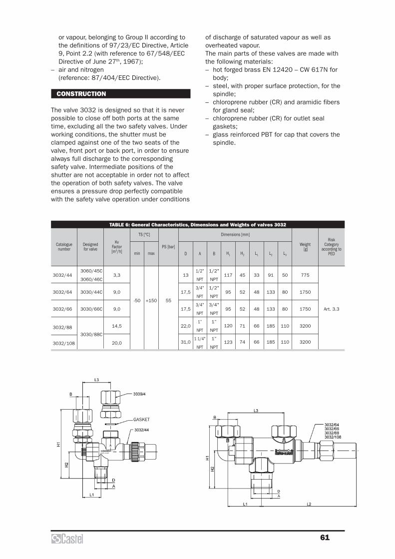
61
of discharge of saturated vapour as well asoverheated vapour.The main parts of these valves are made withthe following materials:– hot forged brass EN 12420 – CW 617N for
body;– steel, with proper surface protection, for the
spindle;– chloroprene rubber (CR) and aramidic fibers
for gland seal;– chloroprene rubber (CR) for outlet seal
gaskets;– glass reinforced PBT for cap that covers the
spindle.
or vapour, belonging to Group II according tothe definitions of 97/23/EC Directive, Article9, Point 2.2 (with reference to 67/548/EECDirective of June 27th, 1967);
– air and nitrogen(reference: 87/404/EEC Directive).
CONSTRUCTION
The valve 3032 is designed so that it is neverpossible to close off both ports at the sametime, excluding all the two safety valves. Underworking conditions, the shutter must beclamped against one of the two seats of thevalve, front port or back port, in order to ensurealways full discharge to the correspondingsafety valve. Intermediate positions of theshutter are not acceptable in order not to affectthe operation of both safety valves. The valveensures a pressure drop perfectly compatiblewith the safety valve operation under conditions
TABLE 6: General Characteristics, Dimensions and Weights of valves 3032
Cataloguenumber
Designedfor valve
KvFactor [m3/h]
RiskCategory
according to PED
Weight[g]
min maxPS [bar]
L3L2L1H2H1
Art. 3.3
Dimensions [mm]TS [°C]
3032/44
3032/64
3032/66
3032/88
3032/108
3060/45C
3060/46C
3030/44C
3030/66C
3030/88C
3,3
9,0
9,0
14,5
20,0
-50 +150 55
117
95
95
120
123
45
52
52
71
74
33
48
48
66
66
91
133
133
185
185
50
80
80
110
110
775
1750
1750
3200
3200
B
1/2"
NPT
1/2"
NPT
3/4"
NPT
1”
NPT
1”
NPT
A
1/2"
NPT
3/4"
NPT
3/4"
NPT
1”
NPT
1 1/4"
NPT
D
13
17,5
17,5
22,0
31,0
GASKET

62
Unions series 3035 allow assembling safetyvalves series 3030 and 3060 or shut-off valvesseries 3032, 3033 and 3063 close to thepressure equipments to protect, set up in arefrigerating system.These unions are designed for installationsaccording to the following two ways:– Make a copper tube jointing the pressure
equipment to the union, fit the end of thistube into the solder connection of the unionand then make a capillary brazing.
– Drill the inner/outer pipe close to thepressure equipment (if possible make acollar on the pipe), put the end of the unioninto this drill and then make a braze welding.
The unions series 3035 are machined by brassbar EN 12164-CW614N.
SAFETY VALVES UNIONS
3060
3035
Tubo di rame
Copper tube
TABLE 7: General Characteristics, Dimensions and Weights of unions 3035
Cataloguenumber ODS
Ø [mm]
PS[bar]
D L Ch
Weight[g]
NPT
Connections Dimensions [mm]
3035/2
3035/3
3035/4
3035/6
3035/8
3035/10
1/4”
3/8”
1/2”
3/4”
1”
1.1/4"
12
18
22
28
36
42
55
18
22
28
35
42
54
33
36,5
44
51
62
67
21
26
32
40
45
55
58
90,5
165
255
364
613
copper tube

63
MARKING
In conformity with the provisions of Article 15 of97/23/EC Directive and of Point 7.3.3 of EN378-2:2008 Standard the following data arereported on the hexagonal nut:• EC marking;• Manufacturer's logo;• Max allowable pressure PS;• Melting point.
INSTALLATION
If a fusible plug is mounted on a pressurevessel or any other part which it protect it shallbe placed in a section where superheatedrefrigerant would not affect its correct function.Fusible plug shall not be covered by thermalinsulation. Discharge from fusible plugs shalltake place so that persons and property are notendangered by the released refrigerant.EN 378-2:2008 Standard, harmonized with the97/23/EC Directive, establishes that a fusibleplug shall not be used as pressure relief deviceon vessels containing refrigerants proper to A2,B1, B2, A3 e B3 groups. The same Standardestablishes that a fusible plug shall not beused as the sole pressure relief devicebetween a refrigerant containing componentand the atmosphere for systems with arefrigerant charge larger than 2,5 kg of groupA1 refrigerant (ex. R22; R134a; R404A;R407C; R410A; R507).
FUSIBLE PLUG SELECTION
97/23/EC Directive requires that pressureequipment, in which permissible limits arereasonably likely to be exceeded, shall be fittedwith suitable protection devices, for instancesafety devices such as fusible plugs. Suchdevices shall prevent pressure frompermanently exceeding the max allowablepressure PS of the equipment they protect. Inany case, a short pressure peak limited to 10%of admissible maximum pressure is permitted.As to the selection and sizing of the suitableprotection device, users shall refer to thespecific sector or product standards.EN 378-2 : 2008 Standard “Refrigeratingsystems and heat pumps – safety andenvironmental requirements – Part 2:Design,construction, testing, marking anddocumentation” provides a general outline ofthe protection devices to be adopted in
GENERAL DESCRIPTION
Fusible plugs series 3080/.C and 3082/.C aresafety devices according to the definition givenin Article 1, Point 2.1.3, 2nd dash of 97/23/ECDirective and are the subject of Article 3, Point1.4 of aforesaid Directive.According to the definition given in Point 3.6.4of EN 378-1:2008 Standard, fusible plug is adevice containing material that melts at apredetermined temperature and therebyrelieving the pressure.Castel has resolved to classify fusible plugsseries 3080/.C and 3082/.C in the Category ofRisk I therefore fixing their use, as protectiondevices, on specific pressure equipments,proper to the same Category of Risk I, incompliance with Annex II, Point 2, of 97/23/ECDirective.In consequence of this choice, fusible plugsseries 3080/.C and 3082/.C cannot be used,as sole protection devices, on pressureequipments proper to Categories of Risk higherthan first.
CONSTRUCTION
The body of the fusible plug is an NPT plugdrilled with a taper hole. A predeterminedquantity of fusible alloy, with checked meltingpoint, is poured inside this hole.The parts of the fusible plugs are made withthe following materials:• Brass EN 12164 – CW 614N, hot tinned, for
the plug.• Eutectic alloy with several components,
cadmium and lead free, for the fusiblematerial.
SCOPE
Use: the fusible plugs are basically used toprotect the components in a refrigeratingsystem or heat pump against possibleoverpressures, with regard to the operatingconditions for which they have been designed,in case of an excessive external heat source,such as fire.Fluids: the fusible plugs can be used withrefrigerant fluids belonging to Group 2according to the definitions of 97/23/ECDirective, Article 9, Point 2.2 (with reference to67/548/EEC Directive of June 27th, 1967).
FUSIBLE PLUGS

64
To find the values of k and C for the moreuseful refrigerants, see the chapter of safetyvalves series 3030Calculation of minimum required dischargecapacity of fusible plug is closely linked to themain cause that may arouse the opening offusible plug, which is the external heat source.The minimum required discharge capacity shallbe determined by the following:
[kg/h]
with– ϕ = density of heat flow rate, it’s
assumed to be 10 [kW/m2]– Asurf = external surface area of the vessel
[m2]– hvap = heat of vaporization of liquid at po
[kJ/kg]
EN 13136 : 2001/A1:2005 Standard alsoestablishes that the following values for Kdr
shall be the maximum used depending on howthe pipe between the vessel and the fusibleplug is mounted on the vessel:• flush or flared connection: Kdr = 0,70• inserted connection: Kdr = 0,55.
QA
hmdsurf
vap
=× ×3600 ϕ
C k
k
k
k= × ×
+
+( )−( )
3 9482
1
1
1,
refrigerating systems and their features (par6.2.5). It also indicates the criteria for theselection of the device suitable to the type andsizes of the system component to be protected(par.6.2.6).EN 13136 : 2001/A1:2005 Standard “Refrigerating systems and heat pumps –Pressure relief devices and their associatedpiping – Methods for calculation”, harmonizedwith 97/23/EC Directive, highlights thepossible causes of overpressure in a systemand makes available to users the instrumentsfor pressure relief device sizing, among whichthe fusible plugs.
SIZING OF FUSIBLE PLUG(REF. EN 13136: 2001/A1:2005)
As the fusible plugs discharge to atmosphere,they always work in critical flow (to know thedefinition of critical flow, see the chapter ofsafety valves series 3030).The fusible plugs must be sized as follow:
[mm2]
with:– Ac = minimum flow area of fusible plug [mm2]– Qmd = minimum required discharge capacity,
of refrigerant, of fusible plug [kg/h]– Kdr =derated coefficient of discharge of
fusible plug, equal to 0,9 x Kd
– po = pressure upstream the fusible plug,inside the equipment to be protected [barabs]
– vo = specific volume of gas or vapour atrelieving conditions po e To , [m3/kg] (To is thefluid temperature at plug inlet, settled by theuser or by the designer)
– C = function of isentropic coefficient k (asmeasured at 25 °C , see Section 7.2.3 , EN13136 : 2001/A1:2005 Standard)calculated from:
A
QC K
vpc
md
dr
o
o
= ××
×3 469,
TABLE 8: General Characteristics, Dimensions and Weights of fusible plugs 3080 e 3082
Cataloguenumber
ConnectionsNPT
FlowDiameter
[mm]
FlowSection[mm2]
Kd PS [bar]
Melting point[°C]
Hexa
gona
l Key Wrench
Torquemin/max
[Nm]
Weight[g]
RiskCategory
according toPED
3080/1C
3080/2C
3080/3C
3080/4C
3082/1C
3082/2C
3082/3C
3082/4C
1/8"
1/4"
3/8"
1/2"
1/8"
1/4"
3/8"
1/2"
4,9
5,7
8,5
9,3
4,9
5,7
8,5
9,3
18,8
25,5
56,7
67,9
18,8
25,5
56,7
67,9
0,91
42
30
79
138
12
17
12
12
17
22
7 / 10
10 / 15
14 / 20
21 / 30
7 / 10
10 / 15
14 / 20
21 / 30
11
23
39
76
11
23
39
76
I

Check valves
66
INSTALLATION
The valves can be installed in any section of arefrigerating system, where it is necessary toavoid an inversion of the refrigerating flow, incompliance with the limits and capacitiesindicated in table 3. Table 1 shows the following functionalcharacteristics of a check valve:– PS;– TS;– Kv factor;– minimum opening pressure differential, that
is the minimum pressure differential betweeninlet and outlet at which a check valve canopen and stay opened.
Before connecting the valve to the pipe it isadvisable to make sure that the refrigeratingsystem is clean. In fact the valves with P.T.F.E.gaskets are particularly sensitive to dirt anddebris. Furthermore check that the flowdirection in the pipe corresponds to the arrowstamped on the body of the valve.
The allowed operating positions are:– types 3122 and 3142 with horizontal axis
and valve cover facing upward;– types 3182 with inlet facing down and the
valve cover facing upward;– types 3112, 3132 and 3133, preferably with
vertical axis and arrow upward. Sloping axis,up to horizontal position, are tolerable.
The brazing of valves with solder connectionsshould be carried out with care, using a lowmelting point filler material. Before starting tobraze, it’s necessary to disassemble the valvesseries 3122, while this operation is notnecessary with solder connection valves. In anycase, it’s important to avoid direct contactbetween the torch flame and the valve body,which could be damaged and compromise theproper functioning of the valve.
APPLICATIONS
The check valves, shown in this chapter, areclassified “Pressure accessories” in the senseof the Pressure Equipment Directive 97/23/EC,Article 1, Section 2.1.4 and are subject ofArticle 3, Section 1.3 of the same Directive.They are designed for installation oncommercial refrigerating systems and on civiland industrial conditioning plants, which userefrigerant fluids proper to the Group II (asdefined in Article 9, Section 2.2 of Directive97/23/EC and referred to in Directive67/548/EEC).For heavy duty, about the operationtemperature, for example installation on thedischarge line close to the compressor, Castelhas developed three new series of valves, types3122, 3142 and 3182, equipped with specialgasket for high temperature, between the bodyand its cover.
MATERIALS
The main parts of the valves are made with thefollowing materials:– hot forged brass EN 12420 – CW 617N for
body and cover;– copper tube EN 12735-1 – Cu-DHP for solder
connections;– austenitic stainless steel AISI 302 for the
spring;– chloroprene rubber (CR) for outlet seal
gaskets. Metal-rubber laminated gaskets forthe valves series 3122, 3142 and 3182;
– P.T.F.E. for seat gasket.
CHECK VALVES

67
TABLE 1: General Characteristics
Catalogue Number
ConnectionsKv Factor [m3/h]
Minimum Opening Pressure Differential
[bar]
TS [°C]PS [bar]
Risk Category according to
PEDSAE Flare
ODS ODM
Ø [in.] Ø [mm] Ø [in.] Ø [mm] min. max.
3112/2 1/4”
– – – –
0,5
0,1
– 40 +105
45
Art. 3.3
3112/3 3/8” 1,5
3112/4 1/2” 1,8
3112/5 5/8” 3,3
3112/6 3/4” 5,0
3122/M22
–
– 22 – 286,6
– 35 +160
3122/7 7/8” – 1.1/8” –
3122/M28 – 28 1.3/8” 358,8
3122/9 1.1/8” – 1.3/8” 35
3122/11 1.3/8” 35 1.5/8”
–
15,2
3122/13 1.5/8” – 2”25,0
I3122/M42 – 42 2”
3122/17 2.1/8” 54
–
40,0
3132/2 1/4” – 0,5
– 40 +105
Art. 3.3
3132/3 3/8” –1,5
3132/M10 – 10
3132/M12 – 121,8
3132/4 1/2” –
3132/5 5/8” 16 3,3
3132/M18 – 18
5,03132/6 3/4” –
3132/7 7/8” 22
3133/M10 – 10 1,4
0,33133/M12 – 12 1,7
3133/5 5/8” 16 3,3
3133/7 7/8” 22 5,0
3142/7 7/8” 22 6,6
0,1 – 35 +160
3142/M28 – 288,8
3142/9 1.1/8” –
3142/11 1.3/8” 35 15,2
3142/13 1.5/8” –25,0
I
3142/M42 – 42
3142/17 2.1/8” 54
40,03142/21 2.5/8” –
3142/25 3.1/8” –
3182/7 7/8” 22 8,5
Art. 3.33182/M28 – 28
9,53182/9 1.1/8” –
3182/11 1.3/8” 35 19,0
3182/13 1.5/8” –37,0
I3182/M42 – 42
3182/17 2.1/8” 54 45,4

68
TABLE 2: Dimensions and Weights
Cataloguenumber
Weight[g]
H H1 L L1 Q Ø D Ch
56
68
73
85
98
84,5
101,5
125,5
142
92
107
132
139
165
107
132
139
165
84,5
101,5
125,5
142
151
177
221
–
28,5
34
37
42,5
–
28,5
34
37
42,5
95
109,5
123,5
–
100
118
141
173
–
170
201
232
256
285
329
130,5
150
195,5
–
100,5
116
143,5
–
60
68
88
104
–
60
68
88
104
60
68
104
16
20
22
27
33
–
16
20
22
27
33
20
22
27
33
–
14
18
20
24
30
–
70
110
140
220
350
1180
1090
1625
2955
4225
95
110
145
210
310
110
145
210
310
1320
1885
3315
4875
5690
1280
1295
1855
3255
4780
Dimensions [mm]
3112/2
3112/3
3112/4
3112/5
3112/6
3122/M22
3122/7
3122/M28
3122/9
3122/11
3122/13
3122/M42
3122/17
3132/2
3132/3
3132/M10
3132/M12
3132/4
3132/5
3132/M18
3132/6
3132/7
3133/M10
3133/M12
3133/5
3133/7
3142/7
3142/M28
3142/9
3142/11
3142/13
3142/M42
3142/17
3142/21
3142/25
3182/7
3182/M28
3182/9
3182/11
3182/13
3182/M42
3182/17
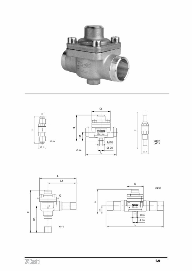
69
3122
3142
3182
Ch
H H
DØDØ
313231333112
Ch
H H
DØDØ
313231333112
3112 31323133
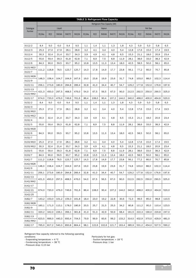
70
TABLE 3: Refrigerant Flow Capacity
Catalogue Number
Refrigerant Flow Capacity [kW]
Liquid Vapour Hot Gas
R134a R22 R404A R407C R410A R134a R22 R404A R407C R410A R134a R22 R404A R407C R410A
3112/2 8,4 9,0 6,0 9,4 9,5 1,1 1,4 1,1 1,3 1,8 4,3 5,9 5,0 5,8 6,5
3112/3 25,3 27,0 17,9 28,1 28,6 3,2 4,1 3,4 4,0 5,4 12,8 17,6 15,0 17,4 19,5
3112/4 30,3 32,4 21,4 33,7 34,3 3,9 4,9 4,1 4,8 6,5 15,3 21,1 18,0 20,9 23,4
3112/5 55,6 59,4 39,3 61,8 62,8 7,1 8,9 7,5 8,8 11,9 28,1 38,6 33,0 38,3 42,9
3112/6 84,3 90,0 59,5 93,7 95,2 10,8 13,5 11,3 13,4 18,0 42,5 58,5 50,0 58,1 65,0
3122/M22111,2 118,8 78,5 123,7 125,7 14,3 17,8 14,9 17,7 23,8 56,1 77,2 66,0 76,7 85,8
3122/7
3122/M28148,3 158,4 104,7 164,9 167,6 19,0 23,8 19,9 23,6 31,7 74,8 103,0 88,0 102,3 114,4
3122/9
3122/11 256,1 273,6 180,9 284,8 289,4 32,8 41,0 34,4 40,7 54,7 129,2 177,8 152,0 176,6 197,6
3122/13421,3 450,0 297,5 468,5 476,0 54,0 67,5 56,5 67,0 90,0 212,5 292,5 250,0 290,5 325,0
3122/M42
3122/17 674,0 720,0 476,0 749,6 761,6 86,4 108,0 90,4 107,2 144,0 340,0 468,0 400,0 464,8 520,0
3132/2 8,4 9,0 6,0 9,4 9,5 1,1 1,4 1,1 1,3 1,8 4,3 5,9 5,0 5,8 6,5
3132/325,3 27,0 17,9 28,1 28,6 3,2 4,1 3,4 4,0 5,4 12,8 17,6 15,0 17,4 19,5
3132/M10
3132/M1230,3 32,4 21,4 33,7 34,3 3,9 4,9 4,1 4,8 6,5 15,3 21,1 18,0 20,9 23,4
3132/4
3132/5 55,6 59,4 39,3 61,8 62,8 7,1 8,9 7,5 8,8 11,9 28,1 38,6 33,0 38,3 42,9
3132/M18
84,3 90,0 59,5 93,7 95,2 10,8 13,5 11,3 13,4 18,0 42,5 58,5 50,0 58,1 65,03132/6
3132/7
3133/M10 25,3 27,0 17,9 28,1 28,6 3,2 4,1 3,4 4,0 5,4 12,8 17,6 15,0 17,4 19,5
3133/M12 30,3 32,4 21,4 33,7 34,3 3,9 4,9 4,1 4,8 6,5 15,3 21,1 18,0 20,9 23,4
3133/5 55,6 59,4 39,3 61,8 62,8 7,1 8,9 7,5 8,8 11,9 28,1 38,6 33,0 38,3 42,9
3133/7 84,3 90,0 59,5 93,7 95,2 10,8 13,5 11,3 13,4 18,0 42,5 58,5 50,0 58,1 65,0
3142/7 111,2 118,8 78,5 123,7 125,7 14,3 17,8 14,9 17,7 23,8 56,1 77,2 66,0 76,7 85,8
3142/M28148,3 158,4 104,7 164,9 167,6 19,0 23,8 19,9 23,6 31,7 74,8 103,0 88,0 102,3 114,4
3142/9
3142/11 256,1 273,6 180,9 284,8 289,4 32,8 41,0 34,4 40,7 54,7 129,2 177,8 152,0 176,6 197,6
3142/13421,3 450,0 297,5 468,5 476,0 54,0 67,5 56,5 67,0 90,0 212,5 292,5 250,0 290,5 325,0
3142/M42
3142/17
674,0 720,0 476,0 749,6 761,6 86,4 108,0 90,4 107,2 144,0 340,0 468,0 400,0 464,8 520,03142/21
3142/25
3182/7 143,2 153,0 101,2 159,3 161,8 18,4 23,0 19,2 22,8 30,6 72,3 99,5 85,0 98,8 110,5
3182/M28160,1 171,0 113,1 178,0 180,9 20,5 25,7 21,5 25,5 34,2 80,8 111,2 95,0 110,4 123,5
3182/9
3182/11 320,2 342,0 226,1 356,1 361,8 41,0 51,3 42,9 50,9 68,4 161,5 222,3 190,0 220,8 247,0
3182/13623,5 666,0 440,3 693,4 704,5 79,9 99,9 83,6 99,2 133,2 314,5 432,9 370,0 429,9 481,0
3182/M42
3182/17 765,0 817,2 540,3 850,8 864,4 98,1 122,6 102,6 121,7 163,4 385,9 531,2 454,0 527,5 590,2
Refrigerant flow capacity referred to the following operating conditions:- Evaporating temperature: + 4 °C- Condensing temperature: + 38 °C- Pressure drop: 0,15 bar
Particularly for hot gas:- Suction temperature: + 18 °C- Pressure drop: 1 bar
Water regulatingvalves
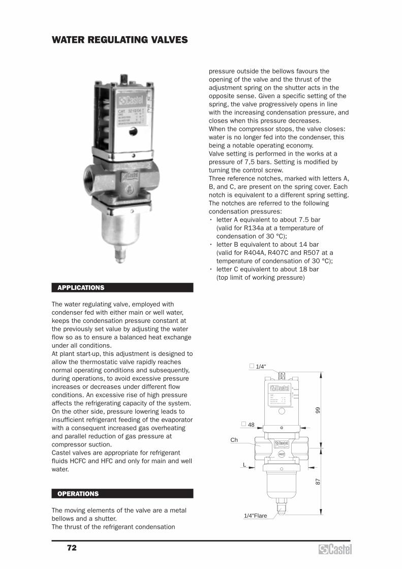
72
APPLICATIONS
The water regulating valve, employed withcondenser fed with either main or well water,keeps the condensation pressure constant atthe previously set value by adjusting the waterflow so as to ensure a balanced heat exchangeunder all conditions. At plant start-up, this adjustment is designed toallow the thermostatic valve rapidly reachesnormal operating conditions and subsequently,during operations, to avoid excessive pressureincreases or decreases under different flowconditions. An excessive rise of high pressureaffects the refrigerating capacity of the system. On the other side, pressure lowering leads toinsufficient refrigerant feeding of the evaporatorwith a consequent increased gas overheatingand parallel reduction of gas pressure atcompressor suction. Castel valves are appropriate for refrigerantfluids HCFC and HFC and only for main and wellwater.
OPERATIONS
The moving elements of the valve are a metalbellows and a shutter. The thrust of the refrigerant condensation
WATER REGULATING VALVES
1/4"
48
Ch
1/4"Flare
8799
L
A02
MADE IN ITALY
RANGE 5-18 bar
MEDIUM R134a-R404A-R12-R22-R502MAX WATER TEMP. 80 |BCMAX WATER PRESS. 10 bar
CAT.BC
A
pressure outside the bellows favours theopening of the valve and the thrust of theadjustment spring on the shutter acts in theopposite sense. Given a specific setting of thespring, the valve progressively opens in linewith the increasing condensation pressure, andcloses when this pressure decreases. When the compressor stops, the valve closes:water is no longer fed into the condenser, thisbeing a notable operating economy.Valve setting is performed in the works at apressure of 7,5 bars. Setting is modified byturning the control screw.Three reference notches, marked with letters A,B, and C, are present on the spring cover. Eachnotch is equivalent to a different spring setting.The notches are referred to the followingcondensation pressures:• letter A equivalent to about 7.5 bar
(valid for R134a at a temperature ofcondensation of 30 °C);
• letter B equivalent to about 14 bar (valid for R404A, R407C and R507 at atemperature of condensation of 30 °C);
• letter C equivalent to about 18 bar (top limit of working pressure)
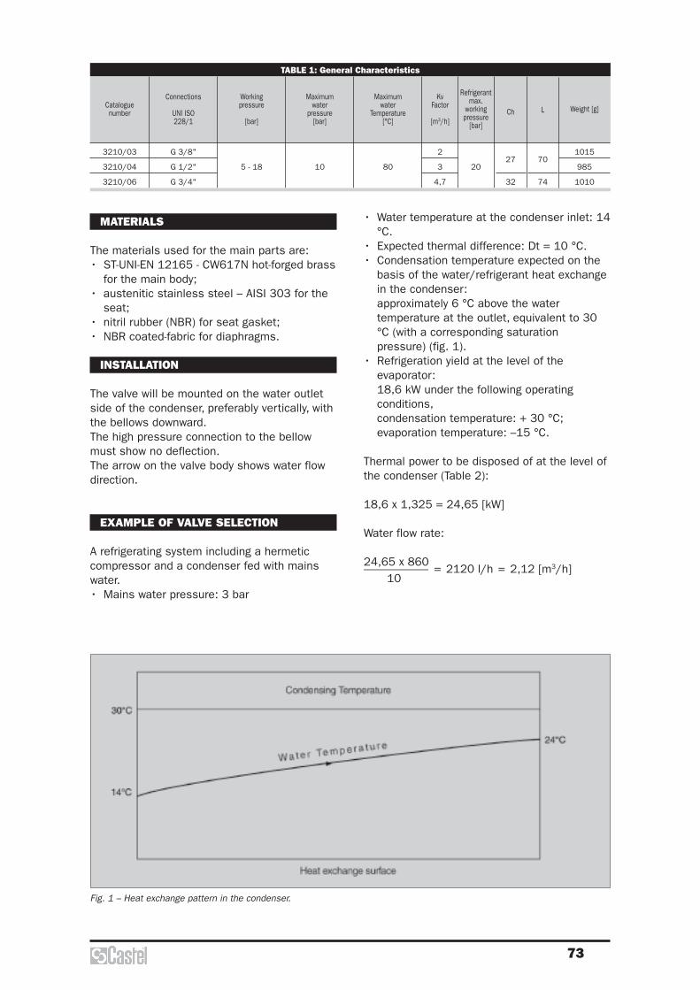
73
• Water temperature at the condenser inlet: 14°C.
• Expected thermal difference: Dt = 10 °C.• Condensation temperature expected on the
basis of the water/refrigerant heat exchangein the condenser:approximately 6 °C above the watertemperature at the outlet, equivalent to 30°C (with a corresponding saturationpressure) (fig. 1).
• Refrigeration yield at the level of theevaporator: 18,6 kW under the following operatingconditions,condensation temperature: + 30 °C;evaporation temperature: –15 °C.
Thermal power to be disposed of at the level ofthe condenser (Table 2):
18,6 x 1,325 = 24,65 [kW]
Water flow rate:
24,65 x 860––––––––––– = 2120 l/h = 2,12 [m3/h]
10
Fig. 1 – Heat exchange pattern in the condenser.
TABLE 1: General Characteristics
Cataloguenumber Weight [g]
Connections
UNI ISO228/1
Working pressure
[bar]
Maximumwater
pressure[bar]
Maximumwater
Temperature[°C]
KvFactor
[m3/h]
Refrigerantmax.
workingpressure
[bar]
Ch L
3210/03
3210/04
3210/06
G 3/8"
G 1/2"
G 3/4"
5 - 18 10 80
2
3
4,7
2027
32
70
74
1015
985
1010
MATERIALS
The materials used for the main parts are:• ST-UNI-EN 12165 - CW617N hot-forged brass
for the main body;• austenitic stainless steel – AISI 303 for the
seat;• nitril rubber (NBR) for seat gasket;• NBR coated-fabric for diaphragms.
INSTALLATION
The valve will be mounted on the water outletside of the condenser, preferably vertically, withthe bellows downward.The high pressure connection to the bellowmust show no deflection.The arrow on the valve body shows water flowdirection.
EXAMPLE OF VALVE SELECTION
A refrigerating system including a hermeticcompressor and a condenser fed with mainswater.• Mains water pressure: 3 bar
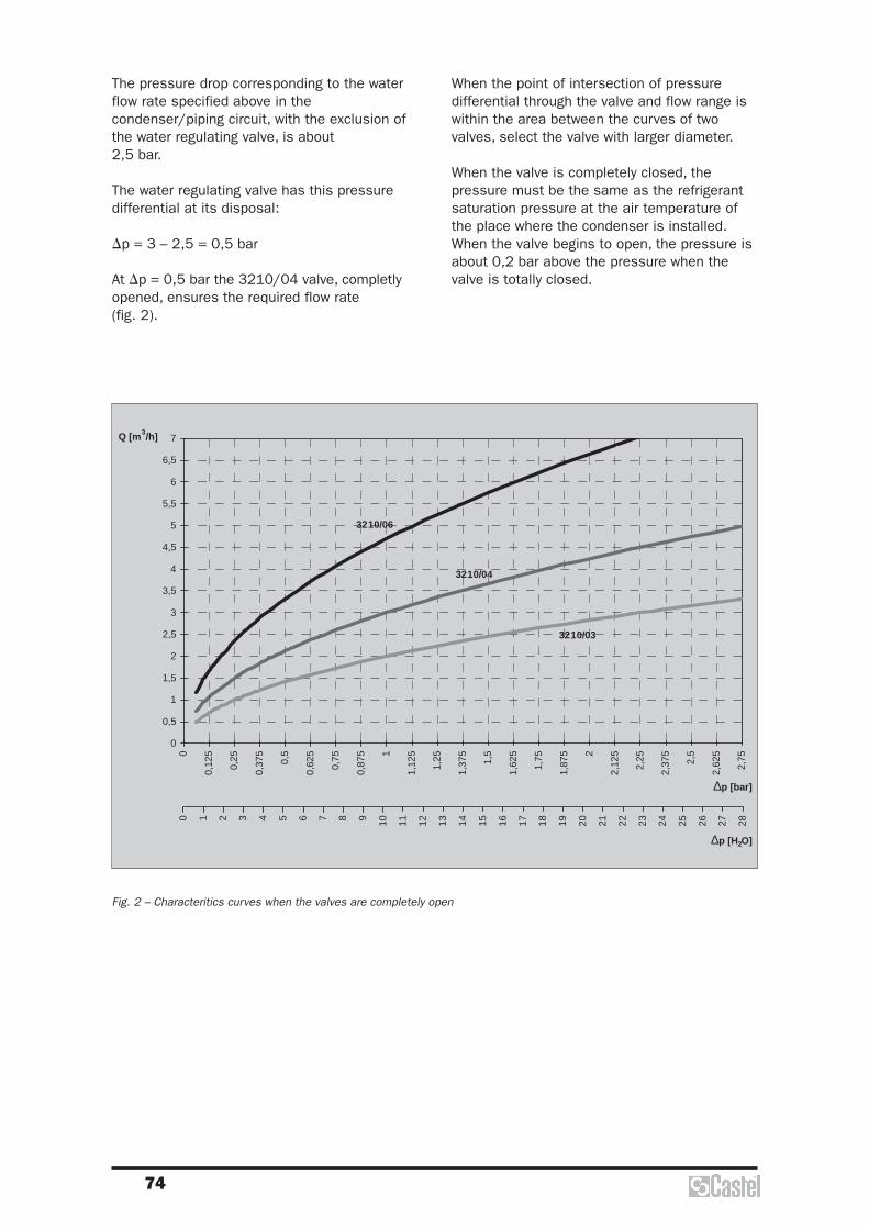
74
When the point of intersection of pressuredifferential through the valve and flow range iswithin the area between the curves of twovalves, select the valve with larger diameter.
When the valve is completely closed, thepressure must be the same as the refrigerantsaturation pressure at the air temperature ofthe place where the condenser is installed.When the valve begins to open, the pressure isabout 0,2 bar above the pressure when thevalve is totally closed.
The pressure drop corresponding to the waterflow rate specified above in thecondenser/piping circuit, with the exclusion ofthe water regulating valve, is about 2,5 bar.
The water regulating valve has this pressuredifferential at its disposal:
Dp = 3 – 2,5 = 0,5 bar
At Dp = 0,5 bar the 3210/04 valve, completlyopened, ensures the required flow rate (fig. 2).
0
0,5
0 1 2 3 4 5 6 7 8 9 10 11 12 13 14 15 16 17 18 19 20 21 22 23 24 25 26 27 28
∆p [H2O]
1
1,5
2
2,5
3
3,5
4
4,5
5
5,5
6
6,5
7
0
0,12
5
0,25
0,37
5
0,5
0,62
5
0,75
0,87
5 1
1,12
5
1,25
1,37
5
1,5
1,62
5
1,75
1,87
5 2
2,12
5
2,25
2,37
5
2,5
2,62
5
2,75
∆p [bar]
Q [m3/h]
3210/04
3210/06
3210/03
Fig. 2 – Characteritics curves when the valves are completely open
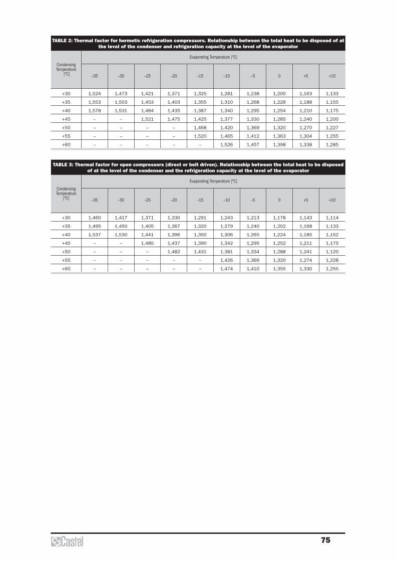
75
TABLE 2: Thermal factor for hermetic refrigeration compressors. Relationship between the total heat to be disposed of atthe level of the condenser and refrigeration capacity at the level of the evaporator
CondensingTemperature
[°C]
Evaporating Temperature [°C]
–35 –30 –25 –20 –15 –10 –5 0 +5 +10
+30
+35
+40
+45
+50
+55
+60
1,524
1,553
1,578
–
–
–
–
1,473
1,503
1,531
–
–
–
–
1,421
1,453
1,484
1,521
–
–
–
1,371
1,403
1,435
1,475
–
–
–
1,325
1,355
1,387
1,425
1,468
1,520
–
1,281
1,310
1,340
1,377
1,420
1,465
1,526
1,238
1,268
1,295
1,330
1,369
1,412
1,457
1,200
1,228
1,254
1,285
1,320
1,363
1,398
1,163
1,188
1,210
1,240
1,270
1,304
1,338
1,133
1,155
1,175
1,200
1,227
1,255
1,285
TABLE 3: Thermal factor for open compressors (direct or belt driven). Relationship between the total heat to be disposedof at the level of the condenser and the refrigeration capacity at the level of the evaporator
CondensingTemperature
[°C]
Evaporating Temperature [°C]
–35 –30 –25 –20 –15 –10 –5 0 +5 +10
+30
+35
+40
+45
+50
+55
+60
1,460
1,495
1,537
–
–
–
–
1,417
1,450
1,530
–
–
–
–
1,371
1,405
1,441
1,485
–
–
–
1,330
1,367
1,396
1,437
1,482
–
–
1,291
1,320
1,350
1,390
1,431
–
–
1,243
1,279
1,306
1,342
1,381
1,426
1,474
1,213
1,240
1,265
1,295
1,334
1,369
1,410
1,178
1,202
1,224
1,252
1,288
1,320
1,355
1,143
1,168
1,185
1,211
1,241
1,274
1,330
1,114
1,133
1,152
1,175
1,120
1,228
1,255


Liquid Indicators &Moisture-Liquid Indicators

78
CONSTRUCTION
New liquid indicators, series 38, and newliquid/moisture indicators, series 39, aremanufactured in a total hermetic constructionto avoid any possible refigerant leaks. Theglass “lens”, with its proper gasket, is housedinto the brass body and is fixed in this seatwith an edge calking operation.
The main parts of the indicators are made withthe following materials:– hot forged brass EN 12420 – CW 617N for
body;– copper tube EN 12735-1 – Cu-DHP for solder
connections;– Glass for lens;– PTFE for outlet seal gaskets;Liquid/moisture indicators series 3770, 3771,3780 and 3781 are manufactured with theglass “lens” directly fused onto a steel metallicring, with proper surface protection.
APPLICATIONS
The indicators, shown in this chapter, areclassified “Pressure accessories” in the senseof the Pressure Equipment Directive 97/23/EC,Article 1, Section 2.1.4 and are subject of Article3, Section 1.3 of the same Directive.The indicators series 3780 are excluded fromthe scope of Directive 97/23/EC, as specified inthe Guidelines 1/8 and 1/9, because they arepiping components.They are designed for installation on commercialrefrigerating systems and on civil and industrialconditioning plants, which use refrigerant fluidsproper to the Group II (as defined in Article 9, Section 2.2 of Directive97/23/EC and referred to in Directive67/548/EEC).Liquid indicators and moisture liquid indicatorsensure a fast and safe inspection of theconditions of the refrigerant fluid in the circuitconcerning regular flow and moisture. Liquidindicators also ensure inspection of the regularreturn of oil to the compressor crankcase.
OPERATION
The moisture/liquid indicators consist of asensitive element as a ring, which changescolor passing from green to yellow according tothe percentage of moisture in the system. Thedata of moisture content, shown in table 1 withthe “green” color, can be consideredadmissible for the proper working of thesystem. When the sensitive element from green
LIQUID INDICATORS &MOISTURE-LIQUID INDICATORS
TABLE 1: Moisture contained in the fluid [p.p.m.]
ColourR22 R134a R404A R407C R410A
Refrigerant fluid
Green
Green
“Chartreuse”
Yellow
<60
60
>60
<75
75
>75
<30
30
>30
<30
30
>30
<30
30
>30
R507
<30
30
>30
fade to yellow, “green Chartreuse”, workingconditions of the system could become difficult.When the sensitive element becomes “yellow”,it’s time to substitute the dehydrator filter.If the charge and working condition are normal,the refrigerant fluid appears perfectly liquidunderneath the “lens” of the indicator. Thepresence of bubbles indicates that therefrigerant fluid is partial evaporating along theliquid line.
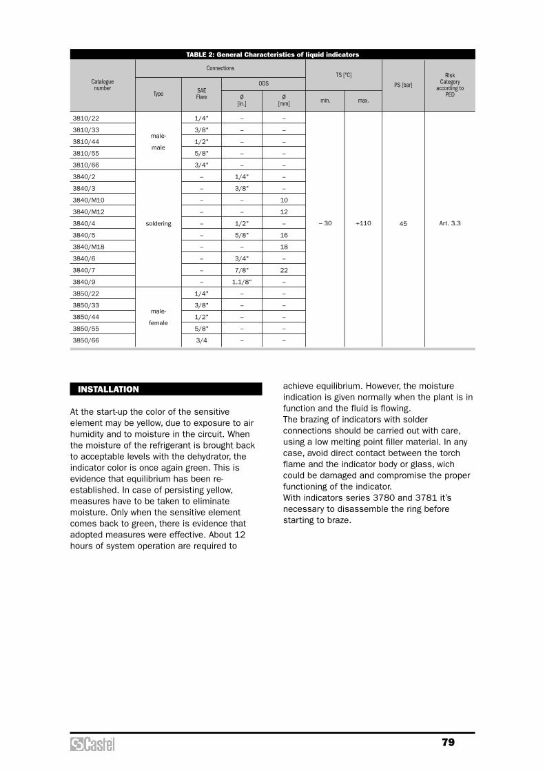
79
TABLE 2: General Characteristics of liquid indicators
Cataloguenumber
Type SAE Flare
RIskCategory
according to PED
PS [bar]ODSTS [°C]
Ø [mm] max.Ø
[in.] min.
Art. 3.3
Connections
male-
male
soldering
male-
female
3810/22
3810/33
3810/44
3810/55
3810/66
3840/2
3840/3
3840/M10
3840/M12
3840/4
3840/5
3840/M18
3840/6
3840/7
3840/9
3850/22
3850/33
3850/44
3850/55
3850/66
1/4"
3/8"
1/2"
5/8"
3/4"
–
–
–
–
–
–
–
–
–
–
1/4"
3/8"
1/2"
5/8"
3/4
–
–
–
–
–
1/4"
3/8"
–
–
1/2"
5/8"
–
3/4"
7/8"
1.1/8"
–
–
–
–
–
–
–
–
–
–
–
–
10
12
–
16
18
–
22
–
–
–
–
–
–
– 30 +110 45
achieve equilibrium. However, the moistureindication is given normally when the plant is infunction and the fluid is flowing.The brazing of indicators with solderconnections should be carried out with care,using a low melting point filler material. In anycase, avoid direct contact between the torchflame and the indicator body or glass, wichcould be damaged and compromise the properfunctioning of the indicator.With indicators series 3780 and 3781 it’snecessary to disassemble the ring beforestarting to braze.
INSTALLATION
At the start-up the color of the sensitiveelement may be yellow, due to exposure to airhumidity and to moisture in the circuit. Whenthe moisture of the refrigerant is brought backto acceptable levels with the dehydrator, theindicator color is once again green. This isevidence that equilibrium has been re-established. In case of persisting yellow,measures have to be taken to eliminatemoisture. Only when the sensitive elementcomes back to green, there is evidence thatadopted measures were effective. About 12hours of system operation are required to

80
1/4"
3/8"
1/2"
5/8"
3/4"
–
–
–
–
–
–
–
–
–
–
1/4"
3/8"
1/2"
5/8"
3/4"
–
–
–
–
–
–
–
–
TABLE 3: General Characteristics of liquid / moisture indicators
Cataloguenumber
Type SAE Flare
RiskCategoryaccording
to PED
PS [bar]
ODS ODM for pipeTS [°C]
Ø [mm]
Ø [mm]
Ø [mm]
Ø hole[mm] max.Ø
[in.]Ø
[in.]Ø
[in.] min.
Art. 3.3
I
Art. 3.3
I
Excluded
Connections
3910/22
3910/33
3910/44
3910/55
3910/66
3940/2
3940/3
3940/M10
3940/M12
3940/4
3940/5
3940/M18
3940/6
3940/7
3940/9
3950/22
3950/33
3950/44
3950/55
3950/66
3770/M28
3770/11
3770/13
3770/M42
3771/11
3771/M42
3771/17
3780/5
3780/M18
3780/7
3780/9
3780/11
3781/M28
male-
male
soldering
male-
female
soldering
saddle
type
level glass
–
–
–
–
–
1/4"
3/8"
–
–
1/2"
5/8"
–
3/4"
7/8"
1.1/8"
–
–
–
–
–
–
–
–
–
1.3/8"
–
2.1/8"
–
–
–
–
–
–
–
–
10
12
–
16
18
–
22
–
–
–
–
–
–
–
–
–
–
35
42
–
–
–
–
–
–
–
–
–
–
–
–
–
–
–
–
–
–
–
–
–
–
–
1.3/8"
1.5/8"
–
–
–
–
–
–
–
–
–
–
–
–
–
–
–
–
–
–
–
–
–
–
–
–
–
28
35
–
42
–
–
–
–
–
5/8"
–
7/8"
1.1/8"
1.3/8"
–
–
16
18
22
28
35
–
–
28
– 30 +110
45
35
38103910
38403940 3850
3950
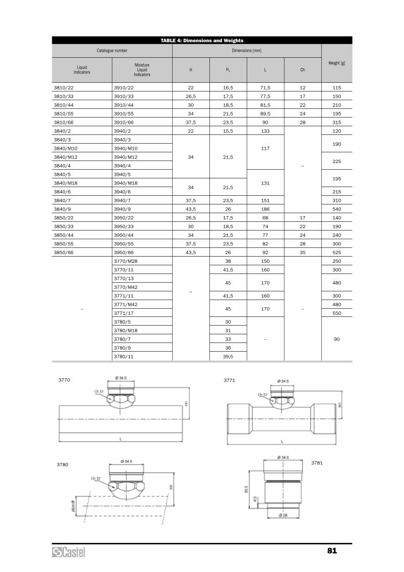
81
3770 3771
3780 3781
MoistureLiquid
IndicatorsH H1 L Ch
22
26,5
30
34
37,5
22
34
34
37,5
43,5
26,5
30
34
37,5
43,5
–
71,5
77,5
81,5
89,5
90
133
117
131
151
186
68
74
77
82
92
150
160
170
160
170
–
12
17
22
24
28
–
17
22
24
28
35
–
Catalogue number
TABLE 4: Dimensions and Weights
LiquidIndicators
Weight [g]
3910/22
3910/33
3910/44
3910/55
3910/66
3940/2
3940/3
3940/M10
3940/M12
3940/4
3940/5
3940/M18
3940/6
3940/7
3940/9
3950/22
3950/33
3950/44
3950/55
3950/66
3770/M28
3770/11
3770/13
3770/M42
3771/11
3771/M42
3771/17
3780/5
3780/M18
3780/7
3780/9
3780/11
Dimensions [mm]
3810/22
3810/33
3810/44
3810/55
3810/66
3840/2
3840/3
3840/M10
3840/M12
3840/4
3840/5
3840/M18
3840/6
3840/7
3840/9
3850/22
3850/33
3850/44
3850/55
3850/66
–
115
150
210
195
315
120
190
225
195
215
310
540
140
190
240
300
525
250
300
480
300
480
550
90
16,5
17,5
18,5
21,5
23,5
15,5
21,5
21,5
23,5
26
17,5
18,5
21,5
23,5
26
38
41,5
45
41,5
45
30
31
33
36
39,5


Dehydrators and Filters
84
In molecular sieve driers, with a chargeconstituted by non-agglomerated products,the dehydrating mass is pressed in betweentwo fine steel mesh disks, or two filteringdisks of various material, kept in place by aspring.In solid core driers, dehydrating anddeacidifying products with binders constitutethe block. Water adsorption combines withthe neutralization of acids that may bepresent in the refrigerant, and with a strongfiltering action.Castel have planned either its productionlines of hermetic driers on this secondsolution that avoid any risk of abrasion of thecharge and consequently the making ofpowder and permit to put the filter in anyposition inside the refrigerating system.It is always advisable to install a moistureindicator downstream the filter, which willshow the refrigerant moisture and,consequently, the degree of efficiency of thefilter.The dehydrating capacity of Castel drier isrelative to the charge of refrigerant and not tothe refrigeration potential of the plant. As amatter of fact, for the same refrigerantpotential and for the same type of refrigerantfluid, there can be different refrigerantcharges according to the type, design andworking conditions of the plant as well as tothe shutter degree.The data shown in the following tables arededuced from the test results of the presentCastel production.It is important to note in the case of a highoil level in the circuit (> 5%) the data shownin the tables will be reduced considerably.
Among contaminating agents causing seriousdamages to refrigerating systems, moistureplays a major role. Its presence, evenpossible in the refrigerating system, is due tomany factors:• inadequate or insufficiently prolonged
vacuum before refrigerant charging;• oil used for topping up remained exposed
to air humidity;• refrigerant used for subsequent additions
contained in non dried vessels;• sealing defects especially in systems not
designed for operation at lowtemperatures.
High temperatures combined with humiditygive rise to complex phenomena enhancingacid formation both in lubricating oil andrefrigerant.Oil organic acids react with metal and favorthe formation of sludge, which are viscousclots consisting of insoluble metal salts andlarge molecules of polymerized oil.Sludge affects the lubrication of the movingelements of the compressor, can clog valvesand filters and cause serious damages.Acids, especially hydrofluoric acid, producedby the hydrolysis of the fluorinated refrigerant(in compressors iron and aluminum act ascatalysts) are particularly corrosive.Acids etch metal surfaces with theconsequent formation of crystal salts, whichstick to surfaces and affect the total heatexchange coefficient in the condenser and inthe evaporator.In the sealed and semi-sealed groups, thesesalts damage the windings of electric motorsas in these groups cold gas cools windingsthrough direct contact.On the other hand, water solubility inrefrigerants in a liquid phase, is quitereduced, especially at low temperatures. As aconsequence, when in the system waterexceeds the very low limits of solubilityadmitted at low temperature, excess waterturns into ice, and blocks expansion valvesand capillaries either partially or totally.Consequently, refrigerating plants must beequipped with a filter drier on the liquid lineand types available on the market areessentially two: molecular sieve driers andsolid core driers.
DEHYDRATION OF REFRIGERANTS
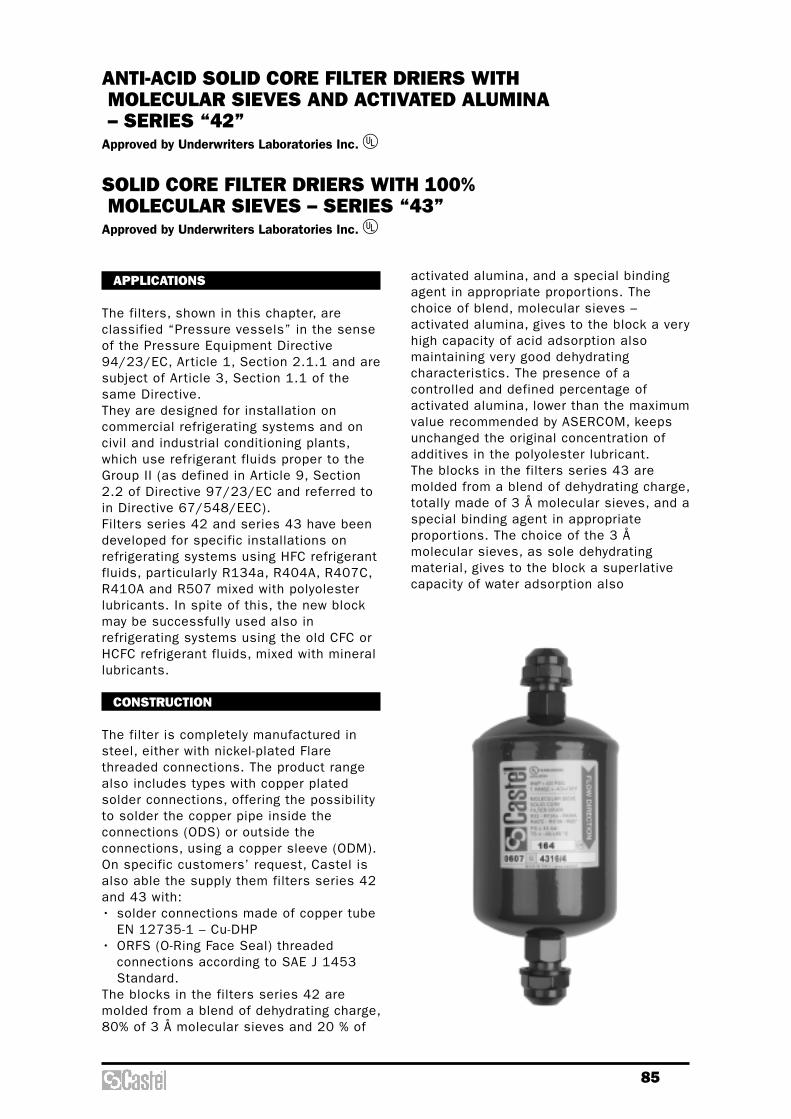
85
activated alumina, and a special bindingagent in appropriate proportions. Thechoice of blend, molecular sieves –activated alumina, gives to the block a veryhigh capacity of acid adsorption alsomaintaining very good dehydratingcharacteristics. The presence of acontrolled and defined percentage ofactivated alumina, lower than the maximumvalue recommended by ASERCOM, keepsunchanged the original concentration ofadditives in the polyolester lubricant.The blocks in the filters series 43 aremolded from a blend of dehydrating charge,totally made of 3 Å molecular sieves, and aspecial binding agent in appropriateproportions. The choice of the 3 Åmolecular sieves, as sole dehydratingmaterial, gives to the block a superlativecapacity of water adsorption also
APPLICATIONS
The filters, shown in this chapter, areclassified “Pressure vessels” in the senseof the Pressure Equipment Directive94/23/EC, Article 1, Section 2.1.1 and aresubject of Article 3, Section 1.1 of thesame Directive.They are designed for installation oncommercial refrigerating systems and oncivil and industrial conditioning plants,which use refrigerant fluids proper to theGroup II (as defined in Article 9, Section2.2 of Directive 97/23/EC and referred toin Directive 67/548/EEC).Filters series 42 and series 43 have beendeveloped for specific installations onrefrigerating systems using HFC refrigerantfluids, particularly R134a, R404A, R407C,R410A and R507 mixed with polyolesterlubricants. In spite of this, the new blockmay be successfully used also inrefrigerating systems using the old CFC orHCFC refrigerant fluids, mixed with minerallubricants.
CONSTRUCTION
The filter is completely manufactured insteel, either with nickel-plated Flarethreaded connections. The product rangealso includes types with copper platedsolder connections, offering the possibilityto solder the copper pipe inside theconnections (ODS) or outside theconnections, using a copper sleeve (ODM).On specific customers’ request, Castel isalso able the supply them filters series 42and 43 with:• solder connections made of copper tube
EN 12735-1 – Cu-DHP• ORFS (O-Ring Face Seal) threaded
connections according to SAE J 1453Standard.
The blocks in the filters series 42 aremolded from a blend of dehydrating charge,80% of 3 Å molecular sieves and 20 % of
ANTI-ACID SOLID CORE FILTER DRIERS WITHMOLECULAR SIEVES AND ACTIVATED ALUMINA– SERIES “42”
Approved by Underwriters Laboratories Inc. u
SOLID CORE FILTER DRIERS WITH 100%MOLECULAR SIEVES – SERIES “43”
Approved by Underwriters Laboratories Inc. u

86
Solid core dehydrator1 – Spring2 – Block3 – Felt4 – Stainless steel mesh
maintaining quite good deacidifyingcharacteristics.The manufacturing process gives aconsiderable compacted ness andstoutness to both the products so thatthey are resistant to shocks andabrasions.The shape of the block is designed in
order to offer the maximum possiblesurface area to the incoming fluid. Theinternal cavity is also positioned in such away as to have a uniform wall thickness.As a result, the fluid encounters aconstant strength at all points, flowslinearly through the block, and ensuresefficient dehydration and minimum chargeloss.The block is chemically inert, notdeliquescent, does not react withrefrigerating fluids, and is capable ofblocking oil by-products dragged into thecircuit. Impurities accumulate in the ringbetween the metal shell and the block; thisprevents filter clogging.
EXAMPLE OF SELECTION
System data:Refrigerant: R407CCondensing temperature: + 50 [°C]Weight of refrigerant: 34 [kg]
According to DIN 8949:2000, the adsorptioncapacity of the drier is given by:
(1.050 – 50) x 34 / 1.000 = 34 g of H2O
where:
1.050 ppm. = moisture in the refrigerantentering the filter according to DIN 8949:200050 ppm. = moisture in the refrigerant flowingout the filter according to DIN 8949:2000
Comparing the absorption capacity requiredwith the values shown in table 3, driermod.4341 should be selected, with a waterabsorption capacity of 40,5 g at 50 °C.If the dehydrating capacity of products isexpressed in water drops, it must beremembered that:
1g H2O = 20 water drops
In this case and when a molecular sieve drier isselected, the following result is obtained:34 x 20 = 680 water drops.
If moisture exceeds the values specified in DIN8949:2000, a drier with a higher adsorptioncapacity shall be selected.
flow
dire
ctio
n
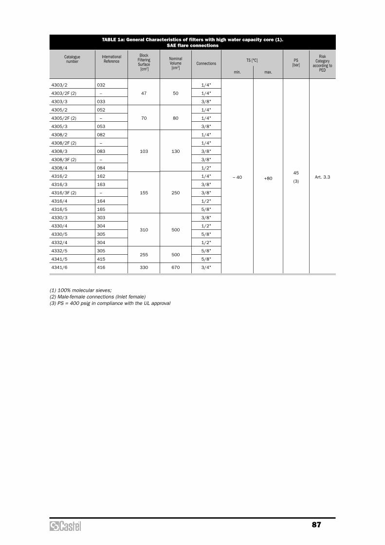
87
TABLE 1a: General Characteristics of filters with high water capacity core (1). SAE flare connections
Cataloguenumber
Block FilteringSurface
[cm2]
NominalVolume[cm3]
1/4"
1/4"
3/8"
1/4"
1/4"
3/8"
1/4"
1/4"
3/8"
3/8"
1/2"
1/4"
3/8"
3/8"
1/2"
5/8"
3/8"
1/2"
5/8"
1/2"
5/8"
5/8"
3/4"
+8045
(3)
Connections
– 40
TS [°C]
4303/2
4303/2F (2)
4303/3
4305/2
4305/2F (2)
4305/3
4308/2
4308/2F (2)
4308/3
4308/3F (2)
4308/4
4316/2
4316/3
4316/3F (2)
4316/4
4316/5
4330/3
4330/4
4330/5
4332/4
4332/5
4341/5
4341/6
032
–
033
052
–
053
082
–
083
–
084
162
163
–
164
165
303
304
305
304
305
415
416
47
70
103
155
310
255
330
50
80
130
250
500
500
670
Art. 3.3
InternationalReference
min. max.
PS[bar]
RiskCategory
according toPED
(1) 100% molecular sieves; (2) Male-female connections (Inlet female)(3) PS = 400 psig in compliance with the UL approval

88
TABLE 1b: General Characteristics of filters with high water capacity core (1).Solder connections
Cataloguenumber
InternationalReference
BlockFilteringSurface
[cm2]
NominalVolume[cm3]
1/4"
1/4"
3/8"
–
1/4"
3/8"
–
–
1/2"
3/8"
–
–
1/2"
5/8"
3/8"
1/2"
5/8"
1/2"
5/8"
5/8"
3/4"
7/8"
1/2"
5/8"
3/4"
7/8"
1.1/8"
–
–
–
10
–
–
10
12
–
–
10
12
–
16
–
–
16
–
16
16
–
–
–
16
–
–
–
3/8"
3/8"
1/2"
–
3/8"
1/2"
–
–
5/8"
1/2"
–
–
5/8"
3/4"
1/2"
5/8"
3/4"
5/8"
3/4"
3/4"
7/8"
1.1/8"
5/8"
3/4"
7/8"
1.1/8"
1.3/8"
–
–
–
12
–
–
12
14
16
–
12
14
16
–
–
16
–
16
–
–
–
–
16
–
–
–
35
– 40 +80
45
(2)
Art. 3.3
I
Ø[in.]
Ø[mm]
Ø[in.]
Ø[mm]
ODS ODM
Connections
min.
TS [°C]
max.
PS[bar]
RiskCategoryaccording
toPED
4303/2S
4305/2S
4305/3S
4305/M10S
4308/2S
4308/3S
4308/M10S
4308/M12S
4308/4S
4316/3S
4316/M10S
4316/M12S
4316/4S
4316/5S
4330/3S
4330/4S
4330/5S
4332/4S
4332/5S
4341/5S
4341/6S
4341/7S
4375/4S
4375/5S
4375/6S
4375/7S
4375/9S
032S
052S
053S
–
082S
083S
–
–
084S
163S
–
–
164S
165S
303S
304S
305S
304S
305S
415S
416S
417S
754S
755S
756S
757S
759S
47
70
103
155
310
255
330
660
50
80
130
250
500
500
670
1340
(1) 100% molecular sieves; (2) PS = 400 psig in compliance with the UL approval
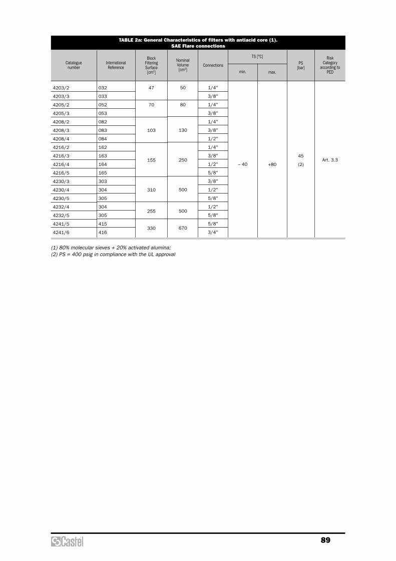
89
TABLE 2a: General Characteristics of filters with antiacid core (1).SAE Flare connections
Catalogue number
InternationalReference
BlockFilteringSurface[cm2]
NominalVolume[cm3]
1/4"
3/8"
1/4"
3/8"
1/4"
3/8"
1/2"
1/4"
3/8"
1/2"
5/8"
3/8"
1/2"
5/8"
1/2"
5/8"
5/8"
3/4"
– 40 +80
45
(2)Art. 3.3
Connectionsmin.
TS [°C]
max.
PS[bar]
RiskCategory
according toPED
4203/2
4203/3
4205/2
4205/3
4208/2
4208/3
4208/4
4216/2
4216/3
4216/4
4216/5
4230/3
4230/4
4230/5
4232/4
4232/5
4241/5
4241/6
032
033
052
053
082
083
084
162
163
164
165
303
304
305
304
305
415
416
47
70
103
155
310
255
330
50
80
130
250
500
500
670
(1) 80% molecular sieves + 20% activated alumina;(2) PS = 400 psig in compliance with the UL approval
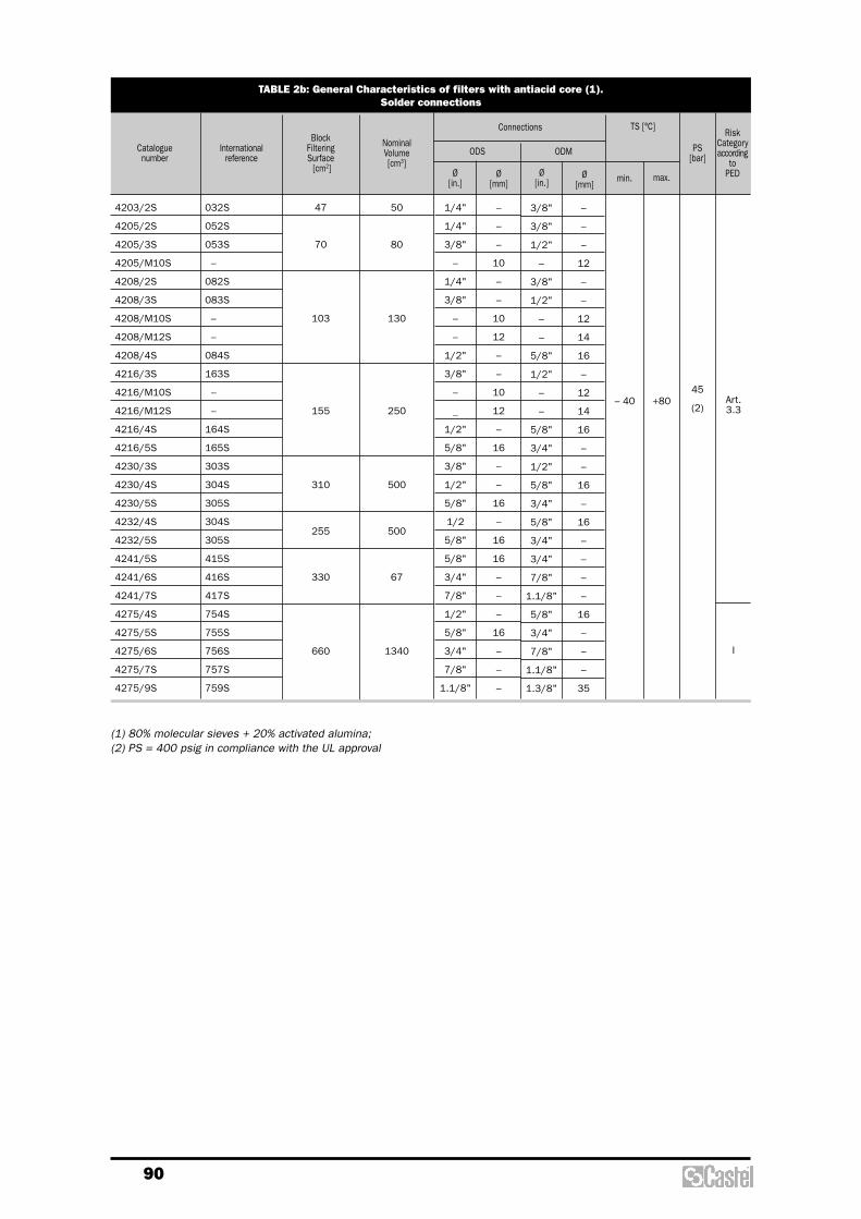
90
TABLE 2b: General Characteristics of filters with antiacid core (1).Solder connections
Cataloguenumber
Internationalreference
BlockFilteringSurface
[cm2]
NominalVolume[cm3]
1/4"
1/4"
3/8"
–
1/4"
3/8"
–
–
1/2"
3/8"
–
_
1/2"
5/8"
3/8"
1/2"
5/8"
1/2
5/8"
5/8"
3/4"
7/8"
1/2"
5/8"
3/4"
7/8"
1.1/8"
–
–
–
10
–
–
10
12
–
–
10
12
–
16
–
–
16
–
16
16
–
–
–
16
–
–
–
3/8"
3/8"
1/2"
–
3/8"
1/2"
–
–
5/8"
1/2"
–
–
5/8"
3/4"
1/2"
5/8"
3/4"
5/8"
3/4"
3/4"
7/8"
1.1/8"
5/8"
3/4"
7/8"
1.1/8"
1.3/8"
–
–
–
12
–
–
12
14
16
–
12
14
16
–
–
16
–
16
–
–
–
–
16
–
–
–
35
– 40 +8045
(2)Art.3.3
I
Ø[in.]
Ø[mm]
Ø[in.]
Ø[mm]
ODS ODM
Connections
min.
TS [°C]
max.
PS[bar]
RiskCategoryaccording
toPED
4203/2S
4205/2S
4205/3S
4205/M10S
4208/2S
4208/3S
4208/M10S
4208/M12S
4208/4S
4216/3S
4216/M10S
4216/M12S
4216/4S
4216/5S
4230/3S
4230/4S
4230/5S
4232/4S
4232/5S
4241/5S
4241/6S
4241/7S
4275/4S
4275/5S
4275/6S
4275/7S
4275/9S
032S
052S
053S
–
082S
083S
–
–
084S
163S
–
–
164S
165S
303S
304S
305S
304S
305S
415S
416S
417S
754S
755S
756S
757S
759S
47
70
103
155
310
255
330
660
50
80
130
250
500
500
67
1340
(1) 80% molecular sieves + 20% activated alumina;(2) PS = 400 psig in compliance with the UL approval
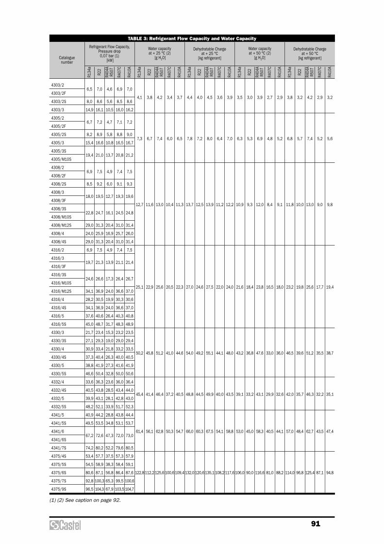
91
(1) (2) See caption on page 92.
TABLE 3: Refrigerant Flow Capacity and Water Capacity
Cataloguenumber
Refrigerant Flow Capacity,Pressure drop0,07 bar (1)
[kW]
R134
a4303/2
4303/2F
4303/2S
4303/3
4305/2
4305/2F
4305/2S
4305/3
4305/3S
4305/M10S
4308/2
4308/2F
4308/2S
4308/3
4308/3F
4308/3S
4308/M10S
4308/M12S
4308/4
4308/4S
4316/2
4316/3
4316/3F
4316/3S
4316/M10S
4316/M12S
4316/4
4316/4S
4316/5
4316/5S
4330/3
4330/3S
4330/4
4330/4S
4330/5
4330/5S
4332/4
4332/4S
4332/5
4332/5S
4341/5
4341/5S
4341/6
4341/6S
4341/7S
4375/4S
4375/5S
4375/6S
4375/7S
4375/9S
6,5
8,0
14,9
6,7
8,2
15,4
19,4
6,9
8,5
18,0
22,8
29,0
24,0
29,0
6,9
19,7
24,6
34,1
28,2
34,1
37,6
45,0
21,7
27,1
30,9
37,3
38,8
46,6
33,6
40,5
39,9
48,2
40,9
49,5
67,2
74,2
53,4
54,5
80,6
92,8
96,5
R22
7,0
8,6
16,1
7,2
8,9
16,6
21,0
7,5
9,2
19,5
24,7
31,3
25,9
31,3
7,5
21,3
26,6
36,9
30,5
36,9
40,6
48,7
23,4
29,3
33,4
40,4
41,9
50,4
36,3
43,8
43,1
52,1
44,2
53,5
72,6
80,2
57,7
58,9
87,1
100,3
104,3
R404
AR5
07
4,6
5,6
10,5
4,7
5,8
10,8
13,7
4,9
6,0
12,7
16,1
20,4
16,9
20,4
4,9
13,9
17,3
24,0
19,9
24,0
26,4
31,7
15,3
19,0
21,8
26,3
27,3
32,8
23,6
28,5
28,1
33,9
28,8
34,8
47,3
52,2
37,5
38,3
56,8
65,3
67,9
R407
C
6,9
8,5
16,0
7,1
8,8
16,5
20,8
7,4
9,1
19,3
24,5
31,0
25,7
31,0
7,4
21,1
26,4
36,6
30,3
36,6
40,3
48,3
23,2
29,0
33,2
40,0
41,6
50,0
36,0
43,4
42,8
51,7
43,8
53,1
72,0
79,6
57,3
58,4
86,4
99,5
103,5
R410
A
7,0
8,6
16,2
7,2
9,0
16,7
21,2
7,5
9,3
19,6
24,8
31,4
26,0
31,4
7,5
21,4
26,7
37,0
30,6
37,0
40,8
48,9
23,5
29,4
33,5
40,5
41,9
50,6
36,4
44,0
43,0
52,3
44,4
53,7
73,0
80,5
57,9
59,1
87,6
100,6
104,7
Water capacity at + 25 °C (2)
[g H2O]
R134
a
4,1
7,3
12,7
25,1
50,2
45,4
61,4
122,8
R22
3,8
6,7
11,6
22,9
45,8
41,4
56,1
112,2
R404
AR5
07
4,2
7,4
13,0
25,6
51,2
46,4
62,8
125,6
R407
C
3,4
6,0
10,4
20,5
41,0
37,2
50,3
100,6
R410
A
3,7
6,5
11,3
22,3
44,6
40,5
54,7
109,4
Dehydratable Chargeat + 25 °C
[kg refrigerant]
R134
a
4,4
7,8
13,7
27,0
54,0
48,8
66,0
132,0
R22
4,0
7,2
12,5
24,6
49,2
44,5
60,3
120,6
R404
AR5
07
4,5
8,0
13,9
27,5
55,1
49,9
67,5
135,1
R407
C
3,6
6,4
11,2
22,0
44,1
40,0
54,1
108,2
R410
A
3,9
7,0
12,2
24,0
48,0
43,5
58,8
117,6
Water capacityat + 50 °C (2)
[g H2O]
R134
a
3,5
6,3
10,9
21,6
43,2
39,1
53,0
106,0
R22
3,0
5,3
9,3
18,4
36,8
33,2
45,0
90,0
R404
AR5
07
3,9
6,9
12,0
23,8
47,6
43,1
58,3
116,6
R407
C
2,7
4,8
8,4
16,5
33,0
29,9
40,5
81,0
R410
A
2,9
5,2
9,1
18,0
36,0
32,6
44,1
88,2
Dehydratable Chargeat + 50 °C
[kg refrigerant]
R134
a
3,8
6,8
11,8
23,2
46,5
42,0
57,0
114,0
R22
3,2
5,7
10,0
19,8
39,6
35,7
48,4
96,8
R404
AR5
07
4,2
7,4
13,0
25,6
51,2
46,3
62,7
125,4
R407
C
2,9
5,2
9,0
17,7
35,5
32,2
43,5
87,1
R410
A
3,2
5,6
9,8
19,4
38,7
35,1
47,4
94,8
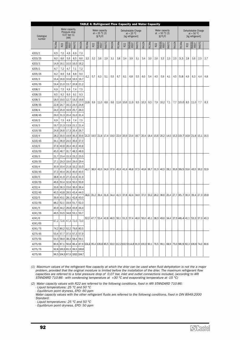
92
TABLE 4: Refrigerant Flow Capacity and Water Capacity
Cataloguenumber
Water capacity,Pressure drop0,07 bar (1)
[kW]
R134
a4203/2
4203/2S
4203/3
4205/2
4205/2S
4205/3
4205/3S
4208/2
4208/2S
4208/3
4208/3S
4208/4
4208/4S
4216/2
4216/3
4216/3S
4216/4
4216/4S
4216/5
4216/5S
4230/3
4230/3S
4230/4
4230/4S
4230/5
4230/5S
4232/4
4232/4S
4232/5
4232/5S
4241/5
4241/5S
4241/6
4241/6S
4241/7S
4275/4S
4275/5S
4275/6S
4275/7S
4275/9S
6,5
8,0
14,9
6,7
8,2
15,4
19,4
6,9
8,5
18,0
22,8
24,0
29,0
6,9
19,7
24,6
28,2
34,1
37,6
45,0
21,7
27,1
30,9
37,3
38,8
46,6
33,6
40,5
39,9
48,2
40,9
49,5
67,2
74,2
53,4
54,5
80,6
92,8
96,5
R22
7,0
8,6
16,1
7,2
8,9
16,6
21,0
7,5
9,2
19,5
24,7
25,9
31,3
7,5
21,3
26,6
30,5
36,9
40,6
48,7
23,4
29,3
33,4
40,4
41,9
50,4
36,3
43,8
43,1
52,1
44,2
53,5
72,6
80,2
57,7
58,9
87,1
100,3
104,3
R404
AR5
07
4,6
5,6
10,5
4,7
5,8
10,8
13,7
4,9
6,0
12,7
16,1
16,9
20,4
4,9
13,9
17,3
19,9
24,0
26,4
31,7
15,3
19,0
21,8
26,3
27,3
32,8
23,6
28,5
28,1
33,9
28,8
34,8
47,3
52,2
37,5
38,3
56,8
65,3
67,9
R407
C
6,9
8,5
16,0
7,1
8,8
16,5
20,8
7,4
9,1
19,3
24,5
25,7
31,0
7,4
21,1
26,4
30,3
36,6
40,3
48,3
23,2
29,0
33,2
40,0
41,6
50,0
36,0
43,4
42,8
51,7
43,8
53,1
72,0
79,6
57,3
58,4
86,4
99,5
103,5
R410
A
7,0
8,6
16,2
7,2
9,0
16,7
21,2
7,5
9,3
19,6
24,8
26,0
31,4
7,5
21,4
26,7
30,6
37,0
40,8
48,9
23,5
29,4
33,5
40,5
41,9
50,6
36,4
44,0
43,0
52,3
44,4
53,7
73,0
80,5
57,9
59,1
87,6
100,6
104,7
(1) Maximum values of the refrigerant flow capacity at which the drier can be used when fluid dehydration is not the a majorproblem, provided that the original moisture is limited before the installation of the drier. The maximum refrigerant flowcapacities are referred to a total pressure drop of 0,07 bar, inlet and outlet connections included, (according to ARISTANDARD 710:86 - with condensing temperature at +30 °C and evaporating temperature at -15 °C)
(2) Water capacity values with R22 are referred to the following conditions, fixed in ARI STANDARD 710:86:- Liquid temperatures: 25 °C and 50 °C- Equilibrium point dryness, EPD: 60 ppmWater capacity values with the other refrigerant fluids are referred to the following conditions, fixed in DIN 8949:2000Standard:- Liquid temperatures: 25 °C and 50 °C- Equilibrium point dryness, EPD: 50 ppm
Water capacityat + 25 °C (2)
[g H2O]
R134
a
3,5
6,2
10,8
21,3
42,7
38,6
52,2
104,4
R22
3,2
5,7
9,9
19,5
38,9
35,2
47,7
95,4
R404
AR5
07
3,6
6,3
11,0
21,8
43,5
39,4
53,4
106,8
R407
C
2,9
5,1
8,8
17,4
34,9
31,6
42,8
85,5
R410
A
3,1
5,5
9,6
19,0
37,9
34,4
46,5
93,0
Dehydratable Chargeat + 25 °C
[kg refrigerant]
R134
a
3,8
6,7
11,6
22,9
45,9
41,5
56,1
112,2
R22
3,4
6,1
10,6
20,9
41,9
37,8
51,3
102,5
R404
AR5
07
3,9
6,8
11,9
23,4
46,8
42,4
57,4
114,8
R407
C
3,1
5,5
9,5
18,7
37,5
34,0
46,0
91,9
R410
A
3,4
6,0
10,3
20,4
40,8
37,0
50,0
100,0
Water capacityat + 50 °C (2)
[g H2O]
R134
a
3,0
5,4
9,3
18,4
36,7
33,2
45,1
90,1
R22
2,6
4,5
7,9
15,6
31,3
28,2
38,3
76,5
R404
AR5
07
3,3
5,9
10,2
20,2
40,5
36,6
49,6
99,1
R407
C
2,3
4,1
7,1
14,0
28,1
25,4
34,4
68,9
R410
A
2,5
4,5
7,7
15,3
30,6
27,7
37,5
75,0
Dehydratable Chargeat + 50 °C
[kg refrigerant]
R134
a
3,3
5,8
10,0
19,7
39,5
35,7
48,4
96,9
R22
2,8
4,9
8,5
16,8
33,6
30,3
41,1
82,3
R404
AR5
07
3,6
6,3
11,0
21,8
43,5
39,4
53,3
106,6
R407
C
2,5
4,4
7,7
15,1
30,2
27,3
37,0
74,0
2,7
4,8
8,3
16,5
32,9
29,8
40,3
80,6

93
TABLE 5: Dimensions and Weights
Catalogue number
4303/2
4303/2F
4303/2S
4303/3
4305/2
4305/2F
4305/2S
4305/3
4305/3S
4305/M10S
4308/2
4308/2F
4308/2S
4308/3
4308/3F
4308/3S
4308/M10S
4308/M12S
4308/4
4308/4S
4316/2
4316/3
4316/3F
4316/3S
4316/M10S
4316/M12S
4316/4
4316/4S
4316/5
4316/5S
4330/3
4330/3S
4330/4
4330/4S
4330/5
4330/5S
4332/4
4332/4S
4332/5
4332/5S
4341/5
4341/5S
4341/6
4341/6S
4341/7S
4375/4S
4375/5S
4375/6S
4375/7S
4375/9S
4203/2
–
4203/2S
4203/3
4205/2
–
4205/2S
4205/3
4205/3S
–
4208/2
–
4208/2S
4208/3
–
4208/3S
–
–
4208/4
4208/4S
4216/2
4216/3
–
4216/3S
–
–
4216/4
4216/4S
4216/5
4216/5S
4230/3
4230/3S
4230/4
4230/4S
4230/5
4230/5S
4232/4
4232/4S
4232/5
4232/5S
4241/5
4241/5S
4241/6
4241/6S
4241/7S
4275/4S
4275/5S
4275/6S
4275/7S
4275/9S
1/4"
1/4"
–
3/8"
1/4"
1/4"
–
3/8"
–
–
1/4"
1/4"
–
3/8"
3/8"
–
–
–
1/2"
–
1/4"
3/8"
3/8"
–
–
–
1/2"
–
5/8"
–
3/8"
–
1/2"
–
5/8"
–
1/2"
–
5/8"
–
5/8"
–
3/4"
–
–
–
–
–
–
–
–
–
1/4"
–
–
–
1/4"
–
3/8"
–
–
–
1/4"
–
–
3/8"
–
–
–
1/2"
–
–
–
3/8"
–
–
–
1/2"
–
5/8"
–
3/8"
–
1/2"
–
5/8"
–
1/2"
–
5/8"
–
5/8"
–
3/4"
7/8"
1/2"
5/8"
3/4"
7/8"
1.1/8"
–
–
–
–
–
–
–
–
–
10
–
–
–
–
–
–
10
12
–
–
–
–
–
–
10
12
–
–
–
16
–
–
–
–
–
16
–
–
–
16
–
16
–
–
–
–
16
–
–
–
52
73
91
103
92
94
111
119
109
110
127
112
146
135
137
154
142
139
146
162
146
158
166
154
151
158
174
158
183
166
245
230
253
237
262
245
187
173
196
179
231
214
232
219
367
373
378
378
378
240
230
220
235
275
260
295
260
380
345
395
380
345
380
430
380
635
690
680
620
630
640
680
640
740
640
1380
1240
1360
1280
1480
1370
1300
1200
1320
1250
1580
1470
1640
1560
1600
2540
2640
2820
2900
3050
SAEFlare Ø
[in.]Ø
[mm] Ø D L
ODS
Connections Dimensions[mm]
Weight[g]
male connections
male - female connections (female - in)
solder connections
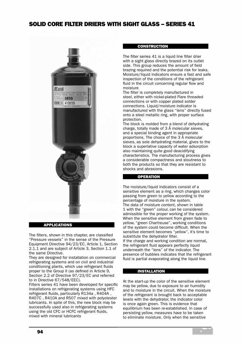
94
APPLICATIONS
The filters, shown in this chapter, are classified “Pressure vessels” in the sense of the Pressure Equipment Directive 94/23/EC, Article 1, Section 2.1.1 and are subject of Article 3, Section 1.1 of the same Directive.They are designed for installation on commercial refrigerating systems and on civil and industrial conditioning plants, which use refrigerant fluids proper to the Group II (as defined in Article 9, Section 2.2 of Directive 97/23/EC and referred to in Directive 67/548/EEC).Filters series 41 have been developed for specific installations on refrigerating systems using HFC refrigerant fluids, particularly R134a , R404A , R407C , R410A and R507 mixed with polyolester lubricants. In spite of this, the new block may be successfully used also in refrigerating systems using the old CFC or HCFC refrigerant fluids, mixed with mineral lubricants
CONSTRUCTION
The filter series 41 is a liquid line filter drier with a sight glass directly brazed on its outlet side. This group reduces the amount of field brazing required and the potential risk for leaks. Moisture/liquid indicators ensure a fast and safe inspection of the conditions of the refrigerant fluid in the circuit concerning regular flow and moistureThe filter is completely manufactured in steel, either with nickel-plated Flare threaded connections or with copper plated solder connections. Liquid/moisture indicator is manufactured with the glass “lens” directly fused onto a steel metallic ring, with proper surface protection.The block is molded from a blend of dehydrating charge, totally made of 3 Å molecular sieves, and a special binding agent in appropriate proportions. The choice of the 3 Å molecular sieves, as sole dehydrating material, gives to the block a superlative capacity of water adsorption also maintaining quite good deacidifying characteristics. The manufacturing process gives a considerable compactness and stoutness to both the products so that they are resistant to shocks and abrasions.
OPERATION
The moisture/liquid indicators consist of a sensitive element as a ring, which changes color passing from green to yellow according to the percentage of moisture in the system.The data of moisture content, shown in table 1 with the “green” colour, can be considered admissible for the proper working of the system. When the sensitive element from green fade to yellow, “green Chartreuse”, working conditions of the system could become difficult. When the sensitive element becomes “yellow”, it’s time to substitute the dehydrator filter.If the charge and working condition are normal, the refrigerant fluid appears perfectly liquid underneath the “lens” of the indicator. The presence of bubbles indicates that the refrigerant fluid is partial evaporating along the liquid line.
INSTALLATION
At the start-up the color of the sensitive element may be yellow, due to exposure to air humidity and to moisture in the circuit. When the moisture of the refrigerant is brought back to acceptable levels with the dehydrator, the indicator color is once again green. This is evidence that equilibrium has been re-established. In case of persisting yellow, measures have to be taken to eliminate moisture. Only when the sensitive
SOLID CORE FILTER DRIERS WITH SIGHT GLASS – SERIES 41
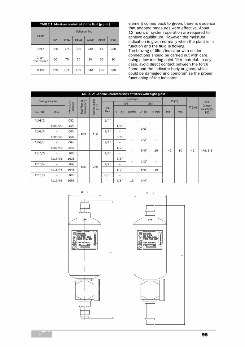
95
TABLE 1: Moisture contained in the fluid [p.p.m.]
Colour
Refrigerant fluid
R22 R134a R404A R407C R410A R507
Green <60 <75 <30 <30 <30 <30
Green Chartreuse”
60 75 30 30 30 30
Yellow >60 >75 >30 >30 >30 >30
TABLE 2: General Characteristics of filters with sight glass
Catalogue Number
Inte
rnat
iona
l Re
fere
nce
Bloc
k Fi
lterin
g Su
rface
[cm
2 ]
Nom
inal
Vol
ume
[cm
3 ]Connections
TS [°C]
PS [bar]
Risk Category
according to PED
SAE Flare
ODS ODM
SAE Flare ODS Ø [in.] Ø [mm] Ø [in.] Ø [mm] min. max.
4108/2 – 082
103 130
1/4” –
– 40 80 45 Art. 3.3
– 4108/2S 082S – 1/4”– 3/8” –
4108/3 – 083 3/8” –
– 4108/3S 083S – 3/8”– 1/2” –
4108/4 – 084 1/2” –
– 4108/4S 084S – 1/2”– 5/8” 16
4116/3 – 163
155 250
3/8” –
– 4116/3S 163S – 3/8”– 1/2” –
4116/4 – 164 1/2” –
– 4116/4S 164S – 1/2” – 5/8” 16
4116/5 – 165 5/8” –
– 4116/5S 165S – 5/8” 16 3/4” –
L
DØ
L
DØ
element comes back to green, there is evidence that adopted measures were effective. About 12 hours of system operation are required to achieve equilibrium. However, the moisture indication is given normally when the plant is in function and the fluid is flowingThe brazing of filter/indicator with solder connections should be carried out with care, using a low melting point filler material. In any case, avoid direct contact between the torch flame and the indicator body or glass, which could be damaged and compromise the proper functioning of the indicator.

96
TABLE 3: Refrigerant Flow Capacity and Water Capacity
Catalogue Number
Refrigerant Flow Capacity, pressure drop 0,07 bar (1)
[kW]
Water Capacity at + 25 °C (2)
[g H2O]
Dehydratable Charge at + 25 °C
[kg refrigerant]
Water Capacity at + 50 °C (2)
[g H2O]
Dehydratable Charge at + 50 °C
[kg refrigerant]
R134
A
R22
R404
A R5
07
R407
C
R410
A
R134
A
R22
R404
A R5
07
R407
C
R410
A
R134
a
R22
R404
A R5
07
R407
C
R410
A
R134
A
R22
R404
A R5
07
R407
C
R410
A
R134
A
R22
R404
A R5
07
R407
C
R410
A
4108/2 6,9 7,5 4,9 7,4 7,5
12,7 11,6 13,0 10,4 11,3 13,7 12,5 13,9 11,2 12,2 11,0 9,3 12,1 8,4 9,1 11,8 10,0 13,0 9,0 9,8
4108/2S 8,5 9,2 6,0 9,1 9,3
4108/3 18,0 19,5 12,7 19,3 19,6
4108/3S 22,8 24,7 16,1 24,5 24,8
4108/4 24,0 25,9 16,9 25,7 26,0
4108/4S 29,0 31,3 20,4 31,0 31,4
4116/3 19,7 21,3 13,9 21,1 21,4
25,1 22,9 25,6 20,5 22,3 27,0 24,6 27,5 22,0 24,0 21,6 18,4 23,8 16,5 18,0 23,2 19,8 25,6 17,7 19,4
4116/3S 24,6 26,6 17,3 26,4 26,7
4116/4 28,2 30,5 19,9 30,3 30,6
4116/4S 34,1 36,9 24,0 36,6 37,0
4116/5 37,6 40,6 26,4 40,3 40,8
4116/5S 45,0 48,7 31,7 48,3 48,9
(1) : Maximum values of the refrigerant flow capacity at which the drier can be used when fluid dehydration is not the a major problem, provided that the original moisture is limited before the installation of the drier. The maximum refrigerant flow capacities are referred to a total pressure drop of 0,07 bar, inlet and outlet connections included, (according to ARI STANDARD 710:86 - with condensing temperature at + 30 °C and evaporating temperature at - 15 °C )
(2) : Water capacity values with R22 are referred to the following conditions, fixed in ARI STANDARD 710:86: - Liquid temperatures: 25 °C and 50 °C - Equilibrium point dryness, EPD: 60 ppm Water capacity values with the other refrigerant fluids are referred to the following conditions, fixed in DIN 8949:2000 Standard: - Liquid temperatures: 25 °C and 50 °C - Equilibrium point dryness, EPD: 50 ppm
TABLE 4: Dimensions and Weights
Catalogue Number
Connections Dimensions [mm] Weight [g]
SAE FlareODS
Ø [in.] Ø [mm] Ø D L
4108/2 1/4" – –
52
182 538
4108/2S – 1/4" – 190 510
4108/3 3/8" – – 191 553
4108/3S – 3/8" – 193 515
4108/4 1/2" – – 198 593
4108/4S – 1/2" – 200 595
4116/3 3/8" – –
73
202 795
4116/3S – 3/8" – 204 780
4116/4 1/2" – – 210 835
4116/4S – 1/2" – 212 805
4116/5 5/8" – – 219 895
4116/5S – 5/8" 16 221 870
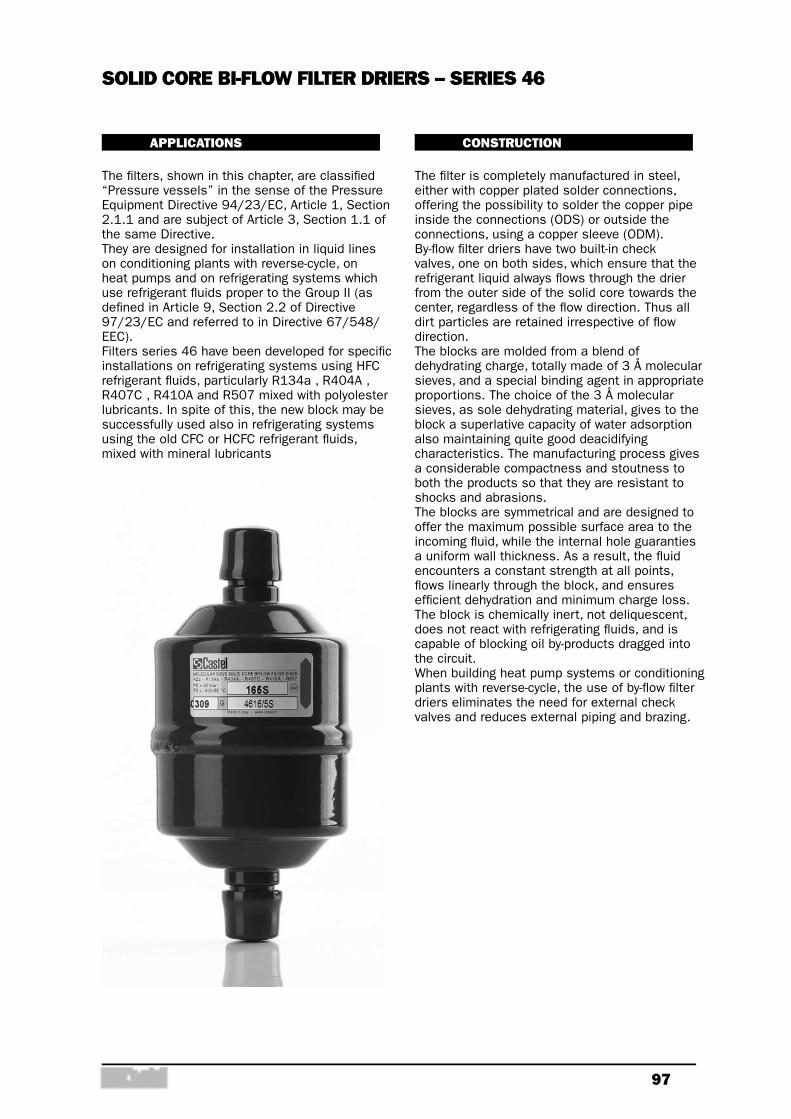
97
APPLICATIONS
The filters, shown in this chapter, are classified “Pressure vessels” in the sense of the Pressure Equipment Directive 94/23/EC, Article 1, Section 2.1.1 and are subject of Article 3, Section 1.1 of the same Directive.They are designed for installation in liquid lines on conditioning plants with reverse-cycle, on heat pumps and on refrigerating systems which use refrigerant fluids proper to the Group II (as defined in Article 9, Section 2.2 of Directive 97/23/EC and referred to in Directive 67/548/EEC).Filters series 46 have been developed for specific installations on refrigerating systems using HFC refrigerant fluids, particularly R134a , R404A , R407C , R410A and R507 mixed with polyolester lubricants. In spite of this, the new block may be successfully used also in refrigerating systems using the old CFC or HCFC refrigerant fluids, mixed with mineral lubricants
CONSTRUCTION
The filter is completely manufactured in steel, either with copper plated solder connections, offering the possibility to solder the copper pipe inside the connections (ODS) or outside the connections, using a copper sleeve (ODM).By-flow filter driers have two built-in check valves, one on both sides, which ensure that the refrigerant liquid always flows through the drier from the outer side of the solid core towards the center, regardless of the flow direction. Thus all dirt particles are retained irrespective of flow direction.The blocks are molded from a blend of dehydrating charge, totally made of 3 Å molecular sieves, and a special binding agent in appropriate proportions. The choice of the 3 Å molecular sieves, as sole dehydrating material, gives to the block a superlative capacity of water adsorption also maintaining quite good deacidifying characteristics. The manufacturing process gives a considerable compactness and stoutness to both the products so that they are resistant to shocks and abrasions.The blocks are symmetrical and are designed to offer the maximum possible surface area to the incoming fluid, while the internal hole guaranties a uniform wall thickness. As a result, the fluid encounters a constant strength at all points, flows linearly through the block, and ensures efficient dehydration and minimum charge loss.The block is chemically inert, not deliquescent, does not react with refrigerating fluids, and is capable of blocking oil by-products dragged into the circuit.When building heat pump systems or conditioning plants with reverse-cycle, the use of by-flow filter driers eliminates the need for external check valves and reduces external piping and brazing.
SOLID CORE BI-FLOW FILTER DRIERS – SERIES 46
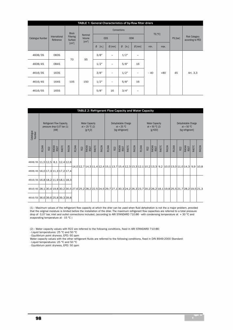
98
TABLE 1: General Characteristics of by-flow filter driers
Catalogue NumberInternational Reference
Block Filtering Surface [cm2]
Nominal Volume [cm3]
Connections
TS [°C]
PS [bar]Risk Category
according to PEDODS ODM
Ø [in.] Ø [mm] Ø [in.] Ø [mm] min. max.
4608/3S 083S
70 95
3/8" – 1/2" –
– 40 +80 45 Art. 3,3
4608/4S 084S 1/2" – 5/8" 16
4616/3S 163S
105 150
3/8" – 1/2" –
4616/4S 164S 1/2" – 5/8" 16
4616/5S 165S 5/8" 16 3/4" –
TABLE 2: Refrigerant Flow Capacity and Water Capacity
Cata
logu
e Nu
mbe
r
Refrigerant Flow Capacity, pressure drop 0,07 bar (1)
[kW]
Water Capacity at + 25 °C (2)
[g H2O]
Dehydratable Charge at + 25 °C
[kg refrigerant]
Water Capacity at + 50 °C (2)
[g H2O]
Dehydratable Charge at + 50 °C
[kg refrigerant]
R134
A
R22
R404
A R5
07
R407
C
R410
A
R134
A
R22
R404
A R5
07
R407
C
R410
A
R134
A
R22
R404
A R5
07
R407
C
R410
A
R134
A
R22
R404
A R5
07
R407
C
R410
A
R134
A
R22
R404
A R5
07
R407
C
R410
A
4608/3S 11,5 12,5 8,1 12,4 12,6
14,0 12,7 14,3 11,4 12,4 15,1 13,7 15,4 12,3 13,3 12,1 10,2 13,3 9,2 10,0 13,0 11,0 14,3 9,9 10,8
4608/4S 16,0 17,3 11,3 17,2 17,4
4616/3S 16,8 18,2 11,9 18,1 18,3
27,6 25,2 28,2 22,5 24,5 29,7 27,1 30,3 24,2 26,3 23,7 20,2 26,2 18,1 19,8 25,5 21,7 28,2 19,5 21,34616/4S 28,1 30,4 19,8 30,2 30,5
4616/5S 36,6 39,6 25,8 39,3 39,8
(1) : Maximum values of the refrigerant flow capacity at which the drier can be used when fluid dehydration is not the a major problem, provided that the original moisture is limited before the installation of the drier. The maximum refrigerant flow capacities are referred to a total pressure drop of 0,07 bar, inlet and outlet connections included, (according to ARI STANDARD 710:86 - with condensing temperature at + 30 °C and evaporating temperature at - 15 °C )
(2) : Water capacity values with R22 are referred to the following conditions, fixed in ARI STANDARD 710:86: - Liquid temperatures: 25 °C and 50 °C - Equilibrium point dryness, EPD: 60 ppm Water capacity values with the other refrigerant fluids are referred to the following conditions, fixed in DIN 8949:2000 Standard: - Liquid temperatures: 25 °C and 50 °C - Equilibrium point dryness, EPD: 50 ppm
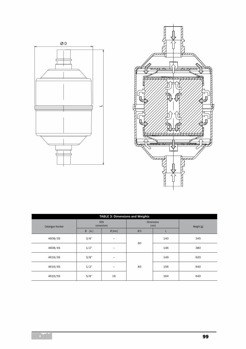
99
TABLE 3: Dimensions and Weights
Catalogue Number
ODS connections
Dimensions [mm] Weight [g]
Ø [in.] Ø [mm] Ø D L
4608/3S 3/8” –
60
140 345
4608/4S 1/2” – 146 380
4616/3S 3/8” –
83
149 620
4616/4S 1/2” – 156 640
4616/5S 5/8” 16 164 640
L
DØ

100
using the old CFC or HCFC refrigerant fluids,mixed with mineral lubricants.The blocks 4490, type A and type B, and theblock 4491, type A, are molded from a blend ofdehydrating charge, totally made of 3 Åmolecular sieves, and a special binding agent inappropriate proportions. The choice of the 3 Åmolecular sieves, as sole dehydrating material,gives to the block a superlative capacity ofwater adsorption also maintaining quite gooddeacidifying characteristics.The blocks 4490, type AA and type AB, and theblock 4491, type AA, are molded from a blend ofdehydrating charge, 80% of 3 Å molecular sievesand 20 % of activated alumina, and a specialbinding agent in appropriate proportions. Thechoice of blend, molecular sieves – activatedalumina, gives to the block a very high capacityof acid adsorption also maintaining very gooddehydrating characteristics. The presence of a controlled and definedpercentage of activated alumina, lower than themaximum value recommended by ASERCOM,keeps unchanged the original concentration ofadditives in the polyolester lubricant.The manufacturing process of blocks series 4490and 4491 gives a considerable compacted ness andstoutness to both the products so that they areresistant to shocks and abrasions.The blocks series 4490 have a volume of 48 cu.in.,equivalent to approx. 800 cm3, and it is used with
FILTER DRIERS WITH REPLACEABLE ANTI-ACID SOLID CORE
Approved by Underwriters Laboratories Inc. uExcept filters 4423/17A, /21A, /25A and4424/25A, /33A
APPLICATIONS
The filters, shown in this chapter, are classified“Pressure vessels” in the sense of thePressure Equipment Directive 97/23/EC,Article 1, Section 2.1.1 and are subject ofArticle 3, Section 1.1 of the same Directive.They are designed for installation oncommercial refrigerating systems and on civiland industrial conditioning plants, which userefrigerant fluids proper to the Group II (asdefined in Article 9, Section 2.2 of Directive97/23/EC and referred to in Directive67/548/EEC).
OPERATIONS
In the case of filters with more than one block,the passage of the fluid takes place in parallel;as a result, the pressure drop does notincrease proportionately to the number ofblocks. A large ring between the block and theinner surface of the filter permits theaccumulation of solid particles, and preventsclogging. Before leaving the filter, the refrigerantfluid must pass through the mesh sieve onwhich blocks are mounted. The danger thatsmall particles of dehydrating material beingintroduced into the system is thus avoided.Furthermore, at filter outlet, a plastic cup, theedge of which closely adheres to the innersurface of the filter, prevents dirt from reachingthe outlet connection during normal operationand block change.
CONSTRUCTION
The filters type 4410 are manufactured in steel,with the exception of the connections which aremade of EN 12735-1 – Cu-DHP copper tube.The filters type 4420 are completelymanufactured in steel and solder connection,are machined with a steel bar EN 10025S355JR.The blocks series 4490 and 4491 has beendeveloped for specific installations onrefrigerating systems using HFC refrigerantfluids, particularly R134a, R404A, R407C,R410A ed R507 mixed with polyolesterlubricants. In spite of this, the new block may besuccessfully used also in refrigerating systems
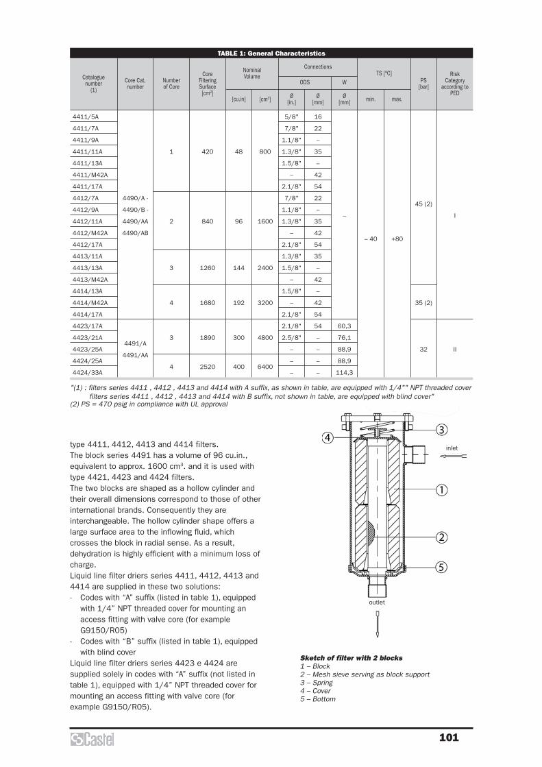
101
type 4411, 4412, 4413 and 4414 filters.The block series 4491 has a volume of 96 cu.in.,equivalent to approx. 1600 cm3. and it is used withtype 4421, 4423 and 4424 filters.The two blocks are shaped as a hollow cylinder andtheir overall dimensions correspond to those of otherinternational brands. Consequently they areinterchangeable. The hollow cylinder shape offers alarge surface area to the inflowing fluid, whichcrosses the block in radial sense. As a result,dehydration is highly efficient with a minimum loss ofcharge.Liquid line filter driers series 4411, 4412, 4413 and4414 are supplied in these two solutions:- Codes with “A” suffix (listed in table 1), equipped
with 1/4” NPT threaded cover for mounting anaccess fitting with valve core (for exampleG9150/R05)
- Codes with “B” suffix (listed in table 1), equippedwith blind cover
Liquid line filter driers series 4423 e 4424 aresupplied solely in codes with “A” suffix (not listed intable 1), equipped with 1/4” NPT threaded cover formounting an access fitting with valve core (forexample G9150/R05).
TABLE 1: General Characteristics
Cataloguenumber
(1)
Core FilteringSurface[cm2]
Numberof Core
Core Cat.number
NominalVolume
5/8"
7/8"
1.1/8"
1.3/8"
1.5/8"
–
2.1/8"
7/8"
1.1/8"
1.3/8"
–
2.1/8"
1.3/8"
1.5/8"
–
1.5/8"
–
2.1/8"
2.1/8"
2.5/8"
–
–
–
800
1600
2400
3200
4800
6400
48
96
144
192
300
400
16
22
–
35
–
42
54
22
–
35
42
54
35
–
42
–
42
54
54
–
–
–
–
–
60,3
76,1
88,9
88,9
114,3
– 40 +80
45 (2)
35 (2)
32
I
II
Ø[in.][cm3][cu.in] Ø
[mm]Ø
[mm]
ODS W
Connections
min.
TS [°C]
max.
PS[bar]
RiskCategory
according toPED
4411/5A
4411/7A
4411/9A
4411/11A
4411/13A
4411/M42A
4411/17A
4412/7A
4412/9A
4412/11A
4412/M42A
4412/17A
4413/11A
4413/13A
4413/M42A
4414/13A
4414/M42A
4414/17A
4423/17A
4423/21A
4423/25A
4424/25A
4424/33A
4490/A -
4490/B -
4490/AA
4490/AB
4491/A
4491/AA
1
2
3
4
3
4
420
840
1260
1680
1890
2520
"(1) : filters series 4411 , 4412 , 4413 and 4414 with A suffix, as shown in table, are equipped with 1/4"" NPT threaded coverfilters series 4411 , 4412 , 4413 and 4414 with B suffix, not shown in table, are equipped with blind cover"
(2) PS = 470 psig in compliance with UL approval
Sketch of filter with 2 blocks1 – Block2 – Mesh sieve serving as block support3 – Spring4 – Cover5 – Bottom
inlet
outlet

102
TABLE 2a: Refrigerant Flow Capacity and Water Capacity (filters)
Cataloguenumber
Refrigerant Flow Capacity,Pressure drop0,07 bar (1)
[kW]
4411/5A
4411/7A
4411/9A
4411/11A
4411/13A
4411/M42A
4411/17A
4412/7A
4412/9A
4412/11A
4412/M42A
4412/17A
4413/11A
4413/13A
4413/M42A
4414/13A
4414/M42A
4414/17A
4423/17A
4423/21A
4423/25A
4424/25A
4424/33A
83
146
200
233
250
146
226
306
333
327
361
426
447
492
670
737
1180
90
158
216
252
270
158
244
331
361
354
391
460
483
532
725
797
1276
59
103
141
164
176
103
159
215
234
230
254
300
315
346
472
519
830
89
156
214
250
268
156
242
328
357
351
387
456
479
527
719
791
1265
90
159
217
253
271
159
245
332
362
355
393
462
485
534
728
800
1281
R134
a
R22
R404
A
R407
C
R410
A
84
168
252
336
504
672
77
154
231
308
462
616
86
172
258
344
516
688
69
138
207
276
414
552
75
150
225
300
450
600
R134
a
R22
R404
A
R407
C
R410
A
90
181
271
361
542
723
83
166
248
331
497
662
92
185
277
370
555
740
74
148
223
297
445
594
81
161
242
323
484
645
R134
a
R22
R404
A
R407
C
R410
A
72
144
216
288
432
576
61
122
183
244
366
488
80
160
240
320
480
640
56
112
168
224
336
448
60
120
180
240
360
480
R134
a
R22
R404
A
R407
C
R410
A
77
155
232
310
465
619
66
131
197
262
394
525
86
172
258
344
516
688
60
120
181
241
361
482
65
129
194
258
387
516
R134
a
R22
R404
A
R407
C
R410
A
Water Capacityat + 25 °C (2)
[g H2O]
Dehydratable Chargeat + 25 °C
[kg refrigerant]
Water Capacityat + 50 °C (2)
[g H2O]
Dehydratable Chargeat + 50 °C
[kg refrigerant]
(1) Maximum values of the refrigerant flow capacity at which the drier can be used when fluid dehydration is not the a majorproblem, provided that the original moisture is limited before the installation of the drier. The maximum refrigerant flowcapacities are referred to a total pressure drop of 0,07 bar, inlet and outlet connections included, (according to ARISTANDARD 710:86 - with condensing temperature at + 30 °C and evaporating temperature at -15 °C)
(2) Water capacity values with R22 are referred to the following conditions, fixed in ARI STANDARD 710:86:- Liquid temperatures: 25 °C and 50 °C- Equilibrium point dryness, EPD: 60 ppmWater capacity values with the other refrigerant fluids are referred to the following conditions, fixed in DIN 8949:2000Standard:- Liquid temperatures: 25 °C and 50 °C- Equilibrium point dryness, EPD: 50 ppm
(3) Maximum values of the refrigerant flow capacity (according to ARI STANDARD 710:86) at which filter driers:- series 4411, 4412, 4413, and 4414 can be used with blocks type 4490/AA and 4490/AB- series 4423 and 4424 can be used with blocks type 4491/AAwhen fluid dehydration is not the a major problem, are the same achieved with block type 4490/A, 4490/B and 4491/A.
TABLE 2b: Refrigerant Flow Capacity and Water Capacity (single block)
Cataloguenumber
Refrigerant Flow Capacity,Pressure drop0,07 bar (1)
[kW]
R134
a
4490/A - 4490/B
4491/A
4490/AA - 4490/AB
4491/AA
–
(3)
84
168
71
143
77
154
65
131
86
172
73
146
69
138
59
117
90
181
77
154
83
166
70
141
92
185
79
157
74
148
63
126
72
144
61
122
61
122
52
104
80
160
68
136
56
112
48
95
77
155
66
132
66
131
56
112
86
12
73
146
60
120
51
102
75
150
64
128
81
161
69
137
60
120
51
102
65
129
55
110
R22
R404
A
R407
C
R410
A
R134
a
R22
R404
A
R407
C
R410
A
R134
a
R22
R404
A
R407
C
R410
A
R134
a
R22
R404
A
R407
C
R410
A
R134
a
R22
R404
A
R407
C
R410
A
Water Capacityat + 25 °C (2)
[g H2O]
Dehydratable Chargeat + 25 °C
[kg refrigerant]
Water Capacityat + 50 °C (2)
[g H2O]
Dehydratable Chargeat + 50 °C
[kg refrigerant]
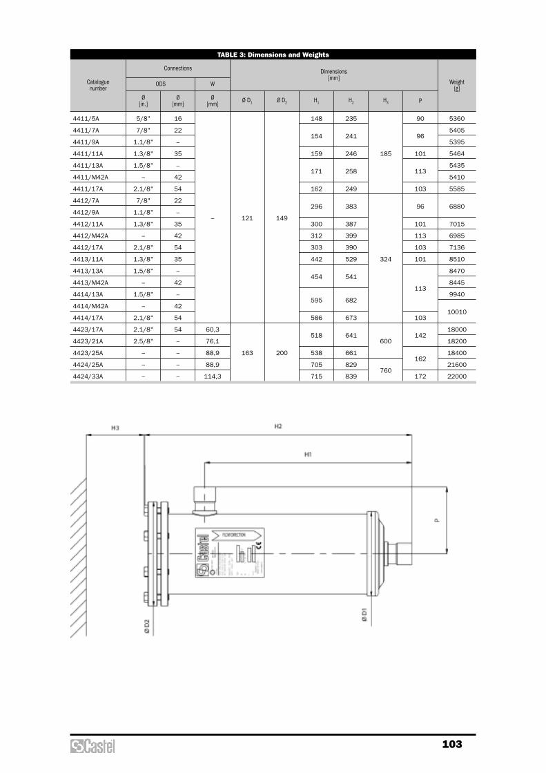
103
TABLE 3: Dimensions and Weights
Cataloguenumber
4411/5A
4411/7A
4411/9A
4411/11A
4411/13A
4411/M42A
4411/17A
4412/7A
4412/9A
4412/11A
4412/M42A
4412/17A
4413/11A
4413/13A
4413/M42A
4414/13A
4414/M42A
4414/17A
4423/17A
4423/21A
4423/25A
4424/25A
4424/33A
5/8"
7/8"
1.1/8"
1.3/8"
1.5/8"
–
2.1/8"
7/8"
1.1/8"
1.3/8"
–
2.1/8"
1.3/8"
1.5/8"
–
1.5/8"
–
2.1/8"
2.1/8"
2.5/8"
–
–
–
16
22
–
35
–
42
54
22
–
35
42
54
35
–
42
–
42
54
54
–
–
–
–
–
60,3
76,1
88,9
88,9
114,3
121
163
149
200
148
154
159
171
162
296
300
312
303
442
454
595
586
518
538
705
715
235
241
246
258
249
383
387
399
390
529
541
682
673
641
661
829
839
185
324
600
760
90
96
101
113
103
96
101
113
103
101
113
103
142
162
172
5360
5405
5395
5464
5435
5410
5585
6880
7015
6985
7136
8510
8470
8445
9940
10010
18000
18200
18400
21600
22000
Ø[in.]
Ø[mm]
Ø[mm]
Ø D1 Ø D2 H1 H2 H3 P
ODS W
Connections Dimensions[mm]
Weight[g]
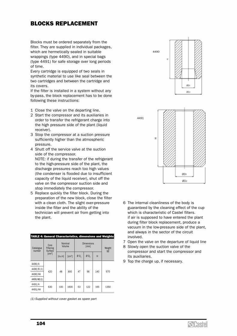
104
Blocks must be ordered separately from thefilter. They are supplied in individual packages,which are hermetically sealed in suitablewrappings (type 4490), and in special bags(type 4491) for safe storage over long periodsof time.Every cartridge is equipped of two seals insynthetic material to use like seal between thetwo cartridges and between the cartridge andits covers.If the filter is installed in a system without anyby-pass, the block replacement has to be donefollowing these instructions:
1 Close the valve on the departing line.2 Start the compressor and its auxiliaries in
order to transfer the refrigerant charge intothe high pressure side of the plant (liquidreceiver).
3 Stop the compressor at a suction pressuresufficiently higher than the atmosphericpressure.
4 Shutt off the service valve at the suctionside of the compressor.NOTE: if during the transfer of the refrigerantto the high-pressure side of the plant, thedischarge pressures reach too high values(the condenser is flooded due to insufficientcapacity of the liquid receiver), shut off thevalve on the compressor suction side andstop immediately the compressor.
5 Replace quickly the filter block. During thepreparation of the new block, close the filterwith a clean cloth. The slight over-pressureinside the filter and the ability of thetechnician will prevent air from getting intothe plant.
BLOCKS REPLACEMENT
TABLE 4: General Characteristics, dimensions and Weights
Cataloguenumber
CoreFilteringSurface[cm2]
4490/A
4490/B (1)
4490/AA
4490/AB (1)
4491/A
4491/AA
420
630
48
100
800
1600
47
53
96
122
140
165
670
1350
[cu.in] [cm3] Ø D1 Ø D2 H
Weight[g]
4490
4491
NominalVolume
Dimensions[mm]
(1) Supplied without cover gasket as spare part
6 The internal cleanliness of the body isguaranteed by the cleaning effect of the cupwhich is characteristic of Castel filters.if air is supposed to have entered the plantduring filter block replacement, produce avacuum in the low-pressure side of the plant,and always in the sector of the circuitinvolved.
7 Open the valve on the departure of liquid line8 Slowly open the suction valve of the
compressor and start the compressor andits auxiliaries.
9 Top the charge up, if necessary.

105
SUCTION LINE:SELECTION CRITERION
With clean systems, refrigerant flow capacityand pressure drops of table 2 are reported to agas speed of 20 m/s for pipes adequate to thefilter connections. For refrigerant flow capacities different from thetable values, under the other same conditions,gas speeds and relative pressure drops throughthe filter can be gained for simpleproportionality.
EXAMPLE
System data:Refrigerant: R407CRefrigerant flow capacity: 130 [kW]Evaporating temperature: + 5 [°C]Suction pipe: Ø 2.1/8”Filter: 4411/17C
In table 2, corresponding to filter type4411/17C refrigerant and evaporatingtemperature, the following data is given:
– refrigerant flow capacity = 141,7 [kW];– pressure drop = 0,21 [bar].
The gas speed in the suction line will be:
[m/s]
Pressure drop through the filter:
[bar]
Remember that the dimensioning of the suctionline in a refrigerating system requires greatattention. In fact the relative pressure loss,included filter, which implies a reduction of flowcapacity sucked by the compressor, influencesdirectly the refrigerating capacity of the plant.This line is normally sized to have a totalpressure loss lower then a variation of thesaturation temperature of 1° C.
0,21130
141,70,177
2
2× =
20130
141,716,8
2
2× =
Approved by Underwriters Laboratories Inc. �Except filters 4421/21C, /25C, /33C
APPLICATIONS
The filters, shown in this chapter, are classified“Pressure vessels” in the sense of thePressure Equipment Directive 97/23/EC,Article 1, Section 2.1.1 and are subject ofArticle 3, Section 1.1 of the same Directive.They are designed for installation oncommercial refrigerating systems and on civiland industrial conditioning plants, which userefrigerant fluids proper to the Group II (asdefined in Article 9, Section 2.2 of Directive97/23/EC and referred to in Directive67/548/EEC).
OPERATION
Good filtering of the refrigerant on the low-pressure side of the system is a guarantee ofprotection for the compressor. Systemcleanliness is ensured by micro filtering cores,which filter out impurities derived frommanufacture and assembly of the refrigeratingsystem.
CONSTRUCTION
The filters type 4410 are manufactured insteel, with the exception of the connectionswhich are made of EN 12735-1 – Cu-DHPcopper tube.The filters type 4420 are completelymanufactured in steel and solder connection,are machined with a steel bar EN 10025S355JR.Zinc plated wire cloths and a filtering baffle form the block, which features a large surface, with controlled porosity. The block can stop solid particles up to 20 micron. At the two ends, soft felt gaskets ensure perfect sealing with the plastic cups. Filters are supplied withan access fitting kit G9150/R05.
MECHANICAL FILTERS WITH REPLACEABLE FILTERINGBLOCK

106
pressure loss in the suction line.To such purpose diagram 2 illustrates theexisting relation between saturationtemperature, in the suction line, and variationof the refrigerant flow capacity of a compressor.
For example diagram 1, referred to R22, allowsto estimate the aforesaid variation in functionof pressure loss and evaporating temperature.After all it’s always important to remember thatthe refrigerant flow capacity of a compressor,under the other same conditions, can reduceconsiderably because of the decrease of thesaturation temperature, consequent to the
TABLE 1: General Characteristics
CatalogueNumber
CoreFilteringSurface[cm2]
Numberof Core
Core Cat.Number
45 (1)
32
I
Ø[in.]
Ø[mm]
Ø[mm]
ODS W
Connections
min.
TS [°C]
max.
PS[bar]
RiskCategory
according toPED
4411/7C
4411/9C
4411/11C
4411/13C
4411/M42C
4411/17C
4411/21C
4421/21C
4421/25C
4421/33C
4495/C
4496/C
1
820
1850
7/8"
1.1/8"
1.3/8"
1.5/8"
–
2.1/8"
2.5/8"
2.5/8"
–
–
22
–
35
–
42
54
–
–
–
–
–
76,1
88,9
114,3
– 40 +80
(1) PS = 470 psig in compliance with the UL approval
Sketch of filter withmechanical block1 – Block2 – Cover3 – Botton4 – Spring
inlet
outlet

107
DIAGRAM 1
DIAGRAM 2
0 5 10 15 20 25 30 350
1
2
3
4
5
6-40 -35
-30
-25
-20
-15
-10-50
+10evapora
tion te
mperature
Pressure loss (kPa)
Equi
vale
nt v
aria
tion
of th
e sa
tura
tion
tem
pera
ture
0
0,5
1
1,5
2
-40 -35 -30 -25 -20 -15 -10 -5 0 5 10
Cor
rect
ion
fact
or o
f ref
riger
ant
flow
cap
acity
Saturation temperature at the suction (°C)
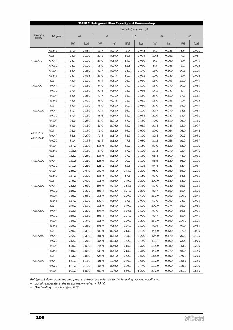
108
TABLE 2: Refrigerant Flow Capacity and Pressure drop
Cataloguenumber Refrigerant
Evaporating Temperature [°C]
[bar][kW][bar][kW][bar][kW][bar][kW][bar][kW]
-30-20-100+5
4411/7C
4411/9C
4411/11C
4411/13C
4411/M42C
4411/17C
4411/21C
4421/21C
4421/25C
4421/33C
R134a
R22
R404A
R407C
R410A
R134a
R22
R404A
R407C
R410A
R134a
R22
R404A
R407C
R410A
R134a
R22
R404A
R407C
R410A
R134a
R22
R404A
R407C
R410A
R134a
R22
R404A
R407C
R410A
R134a
R22
R404A
R407C
R410A
R134a
R22
R404A
R407C
R410A
R134a
R22
R404A
R407C
R410A
13,7
21,5
20,0
19,0
31,7
23,0
36,4
34,0
32,1
53,7
35,0
55,0
51,4
48,6
81,0
50,0
79,0
73,5
69,5
116,0
87,0
137,0
128,0
121,1
202,0
133,5
211,0
197,0
186,4
311,0
133,5
211,0
197,0
186,4
311,0
191,0
302,0
281,0
266,0
446,0
334,0
528,0
491,0
468,0
780,0
0,070
0,100
0,130
0,090
0,200
0,074
0,110
0,140
0,100
0,210
0,075
0,110
0,140
0,100
0,210
0,090
0,130
0,170
0,120
0,250
0,140
0,190
0,270
0,180
0,370
0,250
0,360
0,480
0,330
0,700
0,100
0,150
0,200
0,140
0,300
0,180
0,260
0,340
0,230
0,500
0,540
0,770
1,000
0,690
1,400
9,0
15,6
14,0
12,8
23,0
15,0
26,0
24,0
21,3
38,0
23,0
39,0
36,2
33,2
57,0
33,0
56,0
51,7
47,5
82,0
57,2
97,0
90,0
82,6
143,0
87,5
149,0
138,6
127,0
220,0
87,5
149,0
138,6
127,0
220,0
125,0
213,0
198,0
182,0
315,0
218,0
372,0
346,0
320,0
550,0
0,048
0,074
0,090
0,060
0,140
0,051
0,080
0,100
0,066
0,150
0,052
0,080
0,100
0,068
0,150
0,062
0,090
0,120
0,080
0,180
0,100
0,150
0,190
0,125
0,290
0,180
0,270
0,330
0,210
0,520
0,070
0,110
0,130
0,090
0,200
0,120
0,190
0,220
0,150
0,370
0,360
0,570
0,660
0,440
1,200
6,0
10,8
9,0
8,4
16,0
10,0
18,0
15,0
14,2
26,0
15,0
27,0
22,7
21,9
40,0
21,4
39,0
32,4
31,3
57,0
37,3
66,4
56,5
54,4
98,0
57,0
102,0
87,0
83,7
150,0
57,0
102,0
87,0
83,7
150,0
81,5
146,0
124,0
119,7
215,0
142,0
255,0
217,0
210,0
377,0
0,033
0,052
0,060
0,043
0,100
0,035
0,056
0,070
0,047
0,110
0,036
0,056
0,070
0,047
0,110
0,043
0,064
0,080
0,056
0,120
0,070
0,100
0,130
0,087
0,250
0,120
0,180
0,230
0,150
0,350
0,050
0,074
0,100
0,060
0,150
0,090
0,130
0,170
0,100
0,250
0,270
0,390
0,500
0,300
0,800
3,5
7,2
6,0
5,1
10,6
6,0
12,0
10,0
8,7
17,7
9,0
18,0
14,5
13,4
26,0
13,0
26,0
20,7
19,2
38,0
22,4
44,0
36,0
33,4
65,0
34,3
68,0
55,5
51,4
100,0
34,3
68,0
55,5
51,4
100,0
49,0
97,0
79,3
73,5
143,0
85,0
170,0
138,7
129,0
251,0
0,021
0,037
0,040
0,028
0,100
0,022
0,040
0,050
0,031
0,110
0,023
0,040
0,050
0,031
0,110
0,027
0,046
0,060
0,037
0,100
0,040
0,070
0,100
0,057
0,200
0,070
0,120
0,170
0,100
0,240
0,030
0,050
0,070
0,040
0,100
0,050
0,090
0,120
0,070
0,200
0,150
0,270
0,360
0,200
0,530
0,084
0,120
0,150
0,100
0,230
0,091
0,130
0,160
0,110
0,250
0,092
0,130
0,160
0,110
0,250
0,110
0,150
0,200
0,136
0,300
0,170
0,230
0,310
0,210
0,440
0,300
0,420
0,550
0,380
0,810
0,120
0,170
0,220
0,160
0,340
0,210
0,300
0,390
0,270
0,600
0,630
0,900
1,170
0,790
1,800
17,0
26,0
23,7
22,2
38,4
28,7
43,0
40,0
37,6
63,5
43,5
65,0
60,7
57,0
96,0
62,0
93,0
86,8
81,4
137,0
108,3
162,0
151,3
141,7
239,0
167,0
249,0
232,7
218,0
368,0
167,0
249,0
232,7
218,0
368,0
238,0
356,0
332,0
312,0
526,0
416,0
623,0
581,0
547,0
921,0
Refrigerant flow capacities and pressure drops are referred to the following working conditions: – Liquid temperature ahead expansion valve: + 35 °C– Overheating of suction gas: 6 °C

109
TABLE 4: General Characteristics,dimensions and Weights
Cataloguenumber
44954496
4495/C
4496/C
127
287
820
1850
60
80
87
113
138
168
480
750
[sq.in] [cm2] Ø D1 Ø D2 H
FilteringSurface
Dimensions[mm]
Weight[g]
TABLE 3: Dimensions and Weights
Catalogue Number
4411/7C
4411/9C
4411/11C
4411/13C
4411/M42C
4411/17C
4411/21C
4421/21C
4421/25C
4421/33C
7/8"
1.1/8"
1.3/8"
1.5/8"
–
2.1/8"
2.5/8"
2.5/8"
–
–
22
–
35
–
42
54
–
–
–
–
–
76,1
88,9
114,3
121
163
149
200
154
159
171
162
186
187
205
215
241
246
258
249
273
308
328
338
185
200
96
101
113
103
128
142
162
172
5450
5375
5435
5410
5585
6030
12000
12200
12500
Ø[in.]
Ø[mm]
Ø[mm]
Ø D1 Ø D2 H1 H2 H3 P
ODS W
Connections Dimensions[mm]
Weight[g]
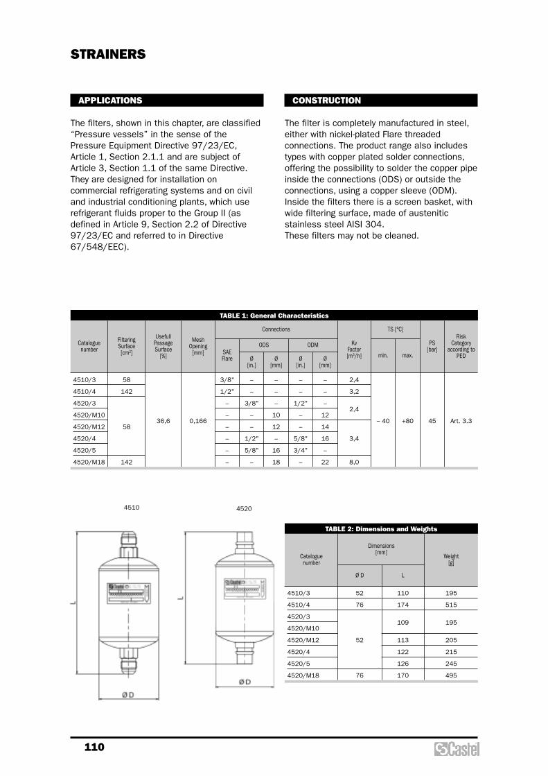
110
CONSTRUCTION
The filter is completely manufactured in steel,either with nickel-plated Flare threadedconnections. The product range also includestypes with copper plated solder connections,offering the possibility to solder the copper pipeinside the connections (ODS) or outside theconnections, using a copper sleeve (ODM).Inside the filters there is a screen basket, withwide filtering surface, made of austeniticstainless steel AISI 304.These filters may not be cleaned.
APPLICATIONS
The filters, shown in this chapter, are classified“Pressure vessels” in the sense of thePressure Equipment Directive 97/23/EC,Article 1, Section 2.1.1 and are subject ofArticle 3, Section 1.1 of the same Directive.They are designed for installation oncommercial refrigerating systems and on civiland industrial conditioning plants, which userefrigerant fluids proper to the Group II (asdefined in Article 9, Section 2.2 of Directive97/23/EC and referred to in Directive67/548/EEC).
STRAINERS
TABLE 1: General Characteristics
Cataloguenumber
UsefullPassageSurface
[%]
MeshOpening
[mm]
KvFactor[m3/h]
FilteringSurface[cm2] SAE
Flare
3/8"
1/2"
–
–
–
–
–
–
–
–
3/8"
–
–
1/2"
5/8"
–
–
–
–
10
12
–
16
18
–
–
1/2"
–
–
5/8"
3/4"
–
–
–
–
12
14
16
–
22
– 40 +80 45 Art. 3.3
Ø[in.]
Ø[mm]
Ø[in.]
Ø[mm]
ODS ODM
Connections
min.
TS [°C]
max.
PS[bar]
RiskCategory
according toPED
4510/3
4510/4
4520/3
4520/M10
4520/M12
4520/4
4520/5
4520/M18
58
142
58
142
36,6 0,166
2,4
3,2
2,4
3,4
8,0
TABLE 2: Dimensions and Weights
Cataloguenumber
4510/3
4510/4
4520/3
4520/M10
4520/M12
4520/4
4520/5
4520/M18
52
76
52
76
110
174
109
113
122
126
170
195
515
195
205
215
245
495
Ø D L
Dimensions[mm]
Weight[g]
4510 4520
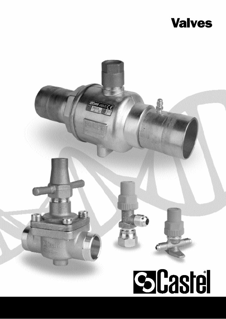
Valves

112
a third one for charging or manometerconnection, types:– 6065 with right access connection;– 6075 with left access connection.
N.B. : the third way must be equiped with avalve core (for example type 8394/A or othersimilar ones) to be ordered separately.
The main parts of the hermetic valves aremade with the following materials:– hot forged brass EN 12420 – CW 617N for
body;– steel, with proper surface protection, or
brass for the spindle;– chloroprene rubber (CR) and aramidic fibers
for gland seal;– glass reinforced PBT for cap that covers the
spindle.
APPLICATIONS
The hermetic valves, shown in this chapter, areclassified “Pressure accessories” in the senseof the Pressure Equipment Directive 97/23/EC,Article 1, Section 2.1.4 and are subject ofArticle 3, Section 1.3 of the same Directive.They are designed for installation oncommercial refrigerating systems and on civiland industrial conditioning plants, which userefrigerant fluids proper to the Group II (asdefined in Article 9, Section 2.2 of Directive97/23/EC and referred to in Directive67/548/EEC).
CONSTRUCTION
These valves are available in the following twotypes:– two-ways shut-off valves types 6010/2 and
6012/22;– three-ways valves; two main connections plus
HERMETIC VALVES
TABLE 1: General Characteristics
Cataloguenumber
KvFactor[m3/h]
–
1/4"
1/4"
1/4"
1/4"
3/8"
1/2"
5/8"
1/4"
3/8"
1/4"
3/8"
3/8"
1/2"
5/8"
1/4"
–
1/4"
3/8"
1/2"
5/8"
–
–
1/4"
–
–
6
10
6
8
10
12
16
0,27
0,39
1,20
2,20
2,80
0,46
1,38
0,46
1,29
1,38
2,55
3,40
-40
+130
+110 45 Art. 3.3
(1) (2) (3) Ø[in.]
Ø[mm]
SAE Flare ODS (4)
Connections
min.
TS [°C]
max.
PS[bar]
Risk Category
according to PED
6010/2
6012/22
6020/222
6020/233
6020/244
6020/255
6065/22M6
6065/23M10
6075/22M6
6075/23M8
6075/23M10
6075/24M12
6075/25M16
6010/2

113
TABLE 2: Dimensions and Weight
Cataloguenumber
H1 H2 H3 H4 H5 I L1 L2 L3 P1
Dimensions [mm]
Weight [g]
6010/2
6012/22
6020/222
6020/233
6020/244
6020/255
6065/22M6
6065/23M10
6075/22M6
6075/23M8
6075/23M10
6075/24M12
6075/25M16
14
25
26,5
25,5
29,5
66
51
52
31
33
31
33
38,5
39,5
–
61
68,5
56,5
58,5
56,5
58,5
68
69
–
115
127
–
–
1
36
–
–
29
62
67
77
79
25
58
55,5
–
25
–
72
84
–
30,5
32
160
145
360
370
520
530
205
200
205
210
220
310
320
6012/22
6020
6065
6075

114
CONSTRUCTION
These valves are available in the following twotypes:– two-ways valves, 90° angle connections,
types 6110 and 6120;– three-ways valves; two main connections
(90° angle) plus a third one for charging, type6132. The access connection may be shutoff by the back-seating of the spindle;
– two-ways valves, 120° angle connections,type 6140.
The main parts of the receiver valves are madewith the following materials:
– hot forged brass EN 12420 – CW 617N forbody;
– steel, with proper surface protection, for thespindle;
– chloroprene rubber (CR) and aramidic fibersfor gland seal;
– glass reinforced PBT for cap that covers thespindle.
APPLICATIONS
The receiver valves, shown in this chapter, areclassified “Pressure accessories” in the senseof the Pressure Equipment Directive 97/23/EC,Article 1, Section 2.1.4 and are subject ofArticle 3, Section 1.3 of the same Directive.They are designed for installation oncommercial refrigerating systems and on civiland industrial conditioning plants, which userefrigerant fluids proper to the Group II (asdefined in Article 9,Section 2.2 of Directive 97/23/EC and referredto in Directive 67/548/EEC).
RECEIVER VALVES
TABLE 1: General Characteristics
Cataloguenumber
KvFactor[m3/h]
–
1/4" f
–
3/8" f
–
1/4"
–
1/4"
1/4"
1/4"
1/4"
3/8"
3/8"
3/8"
1/2"
1/2"
5/8"
3/4"
1/4"
1/4"
3/8"
1/2"
1/2"
5/8"
3/4"
1/4"
3/8"
1/2"
5/8"
1/4"
1/4"
1/8"
1/4"
–
3/8"
1/4"
3/8"
–
3/8"
1/2"
1/2"
3/4"
1/4"
3/8"
3/8"
3/8"
1/2"
1/2"
3/4"
1/4"
3/8"
1/2"
1/2"
1/4"
3/8"
0,44
0,45
1,35
2,40
3,40
6,00
0,44
0,45
1,35
2,40
3,40
6,00
0,45
1,20
2,20
3,85
0,36
-60
+130
+110
+130
45 Art. 3.3
(1) (2) (3)
SAE Flare NPT
Connections
min.
TS [°C]
max.
PS[bar]
RiskCategory
according to PED
6110/21
6110/22
6110/X15
6110/23
6110/32
6110/33
6110/X13
6110/43
6110/44
6110/54
6110/66
6120/22
6120/23
6120/33
6120/43
6120/44
6120/54
6120/66
6132/22
6132/33
6132/44
6132/54
6140/22
6140/23
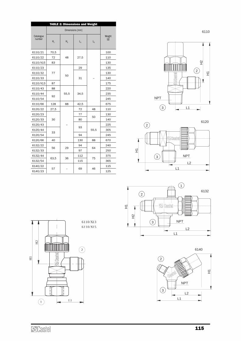
115
H1
H2
L1
2
3
6110
L1
L2
H1
NPT
2
3
6120
H1
L2
L1
NPT
3
2
6140
L2L1
H1
H2
1
2
3 NPT
6132
NPT
H2
H1
L1
6110/X136110/X15
1
2
TABLE 2: Dimensions and Weight
Cataloguenumber
6110/21
6110/22
6110/X15
6110/23
6110/32
6110/33
6110/X13
6110/43
6110/44
6110/54
6110/66
6120/22
6120/23
6120/33
6120/43
6120/44
6120/54
6120/66
6132/22
6132/33
6132/44
6132/54
6140/22
6140/23
70,5
72
83
77
87
88
92
128
27,5
30
33
40
56
63,5
57
48
50
55,5
88
–
29
36
–
27,5
29
31
34,5
42,5
72
77
80
93
94
130
94
97
112
115
69
–
48
50
55,5
88
64
75
46
100
110
130
135
130
140
175
220
235
245
675
110
130
140
225
305
245
670
240
250
375
365
115
125
H1 H2 L1 L2
Dimensions [mm]
Weight [g]

116
The main parts of the stop valves are madewith the following materials:
– hot forged brass EN 12420 – CW 617N forbody;
– brass EN 12164 – CW 614N for spindle andprotection cap;
– chloroprene rubber (CR) for outlet sealgaskets for series 6165 and 6175;
– chloroprene rubber (CR) and aramidic fibersfor gland seal, only for series 6170.
APPLICATIONS
The stop valves, shown in this chapter, areclassified “Pressure accessories” in the senseof the Pressure Equipment Directive 97/23/EC,Article 1, Section 2.1.4 and are subject ofArticle 3, Section 1.3 of the same Directive.They are designed for installation oncommercial refrigerating systems and on civiland industrial conditioning plants, which userefrigerant fluids proper to the Group II (asdefined in Article 9, Section 2.2 of Directive97/23/EC and referred to in Directive67/548/EEC).
CONSTRUCTION
The very compact design of these brass valvesallows minimum dimensional sizes and thefixing flange complies with current marketrequirements.Valves 6170 and 6175 must be completed withthe following devices, to be ordered separately:– valve code 8394/A or code 8394/B;– cap with gasket code 8392/A.
STOP VALVES
TABLE 1: General Characteristics
Cataloguenumber
KvFactor[m3/h]
2
3
–
1/4"
1/4"
3/8"
3/8"
1/2"
5/8"
3/4"
7/8"
1/4"
3/8"
3/8"
1/2"
5/8"
3/4"
7/8"
–
16
–
0,68
1,70
1,70
3,40
4,60
9,00
10,80
-20 +110 45 Art. 3.3
WayNr.
(1) (2) Ø[in.]
Ø[mm]
SAE Flare ODS (3)
Connections
min.
TS [°C]
max.
PS[bar]
RiskCategory
according to PED
6165/22
6165/33
6175/33
6175/44
6175/55
6170/66
6170/77

117
TABLE 2: Dimensions and Weight
Cataloguenumber
H1 H2 H3 Ø D L1 L2 L3 I
Dimensions [mm]
Weight [g]
6165/22
6165/33
6175/33
6175/44
6175/55
6170/66
6170/77
17
20
28,5
52
65
104
8
12
9,5
12,7
15,9
19
22,2
28,6
29
30,5
36
47
–
29
31
36
–
59,5
67
83
38
50
113
120
135
225
235
655
670
I I
L2
L3
H3
L1
H1
H2
L1
H3
H1
H2
BDBD
6170
6165 6175
B 6
.5
B 6
.5
2 2
3 3
1
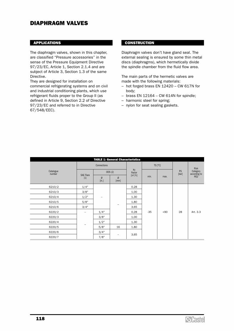
118
CONSTRUCTION
Diaphragm valves don’t have gland seal. Theexternal sealing is ensured by some thin metaldiscs (diaphragms), which hermetically dividethe spindle chamber from the fluid flow area.
The main parts of the hermetic valves aremade with the following materials:– hot forged brass EN 12420 – CW 617N for
body;– brass EN 12164 – CW 614N for spindle;– harmonic steel for spring;– nylon for seat sealing gaskets.
APPLICATIONS
The diaphragm valves, shown in this chapter,are classified “Pressure accessories” in thesense of the Pressure Equipment Directive97/23/EC, Article 1, Section 2.1.4 and aresubject of Article 3, Section 1.3 of the sameDirective.They are designed for installation oncommercial refrigerating systems and on civiland industrial conditioning plants, which userefrigerant fluids proper to the Group II (asdefined in Article 9, Section 2.2 of Directive97/23/EC and referred to in Directive67/548/EEC).
DIAPHRAGM VALVES
TABLE 1: General Characteristics
Cataloguenumber
KvFactor[m3/h]
1/4"
3/8"
1/2"
5/8"
3/4"
–
–
–
1/4"
3/8"
1/2"
5/8"
3/4"
7/8"
–
16
–
0,28
1,00
1,30
1,80
3,65
0,28
1,00
1,30
1,80
3,65
-35 +90 28 Art. 3.3
Ø[in.]
Ø[mm]
SAE Flare(1)
ODS (2)
Connections
min.
TS [°C]
max.
PS[bar]
RiskCategory
according to PED
6210/2
6210/3
6210/4
6210/5
6210/6
6220/2
6220/3
6220/4
6220/5
6220/6
6220/7

119
TABLE 2: Dimensions and Weight
Cataloguenumber
6210/2
6210/3
6210/4
6210/5
6210/6
6220/2
6220/3
6220/4
6220/5
6220/6
6220/7
68
72
86
68
72
86
53,5
62,5
53,5
62,5
58
74
78
98
53
61
70
71
92
94
4,5
6,2
4,5
6,2
36
38
50
36
38
50
52
60
52
60
200
325
335
340
655
195
300
305
580
645
H1 H2 L1 d I D
Dimensions [mm]
Weight[g]
D
L1
d
H2
H1
H2
I
H2
D
H2
H1
H2
H1
d
L1
I
A94 A94
A
1
2 2
6210 6220 6260
1 1
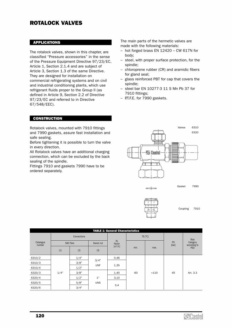
120
The main parts of the hermetic valves aremade with the following materials:– hot forged brass EN 12420 – CW 617N for
body;– steel, with proper surface protection, for the
spindle;– chloroprene rubber (CR) and aramidic fibers
for gland seal;– glass reinforced PBT for cap that covers the
spindle;– steel bar EN 10277-3 11 S Mn Pb 37 for
7910 fittings;– P.T.F.E. for 7990 gaskets.
APPLICATIONS
The rotalock valves, shown in this chapter, areclassified “Pressure accessories” in the senseof the Pressure Equipment Directive 97/23/EC,Article 1, Section 2.1.4 and are subject ofArticle 3, Section 1.3 of the same Directive.They are designed for installation oncommercial refrigerating systems and on civiland industrial conditioning plants, which userefrigerant fluids proper to the Group II (asdefined in Article 9, Section 2.2 of Directive97/23/EC and referred to in Directive67/548/EEC).
CONSTRUCTION
Rotalock valves, mounted with 7910 fittingsand 7990 gaskets, assure fast installation andsafe sealing.Before tightening it is possible to turn the valvein every direction.All Rotalock valves have an additional chargingconnection, which can be excluded by the backsealing of the spindle.Fittings 7910 and gaskets 7990 have to beordered separately.
ROTALOCK VALVES
TABLE 1: General Characteristics
Cataloguenumber
KvFactor[m3/h]
1/4"
1/4"
3/8"
1/2"
3/8"
1/2"
5/8"
3/4"
3/4"
UNF
1"
UNS
0,46
1,35
1,40
3,10
3,4
-60 +110 45 Art. 3.3
(1) (2) (3)
SAE Flare Swivel nut
Connections
min.
TS [°C]
max.
PS[bar]
RiskCategory
according to PED
6310/2
6310/3
6310/4
6320/3
6320/4
6320/5
6320/6
Valves 6310
6320
Gasket 7990
Coupling 7910

121
L2
L1
H1
H2
6310 6320
7990
Guarnizione
7910
Raccordo
12
3
TABLE 2: Dimensions and Weight
Catalogue number
6310/2
6310/3
6310/4
6320/3
6320/4
6320/5
6320/6
68,5
69,5
72
33,5
34,5
36,5
94
97
114,5
117,5
64
77,5
290
300
330
400
415
425
H1 H2 L1 L2
Dimensions [mm]
Weight[g]

122
INSTALLATION
The brazing of capped valves with solderconnections, type 6420, should be carried outwith care, using a low melting point fillermaterial. It‘s necessary to remove the spindleassembly, with gland too, before brazing thebody. It’s important to avoid direct contactbetween the torch flame and the valve body,which could be damaged and compromise theproper functioning of the valve.
APPLICATIONS
The capped valves, shown in this chapter, areclassified “Pressure accessories” in the senseof the Pressure Equipment Directive 97/23/EC,Article 1, Section 2.1.4 and are subject ofArticle 3, Section 1.3 of the same Directive.They are designed for installation oncommercial refrigerating systems and on civiland industrial conditioning plants, which userefrigerant fluids proper to the Group II (asdefined in Article 9, Section 2.2 of Directive97/23/EC and referred to in Directive67/548/EEC).
CONSTRUCTION
The main parts of the capped valves are madewith the following materials:– hot forged brass EN 12420 – CW 617N for
body;– steel, with proper surface protection, for the
spindle;– chloroprene rubber (CR) and aramidic fibers
for gland seal;– glass reinforced PBT for cap that covers the
spindle.
CAPPED VALVES
TABLE 1: General Characteristics
Catalogue number
KvFactor[m3/h]
1/4"
3/8"
1/2"
5/8"
3/4"
–
1/4"
–
1/4"
–
1/4"
3/8"
–
1/2"
5/8"
–
3/4"
–
7/8"
–
–
10
12
–
16
18
–
22
–
0,40
1,00
1,45
1,70
3,50
0,40
1,00
1,45
1,70
3,50
0,35
-60 +110 45 Art. 3.3
Ø[in.]
Ø[mm]
SAE Flare
(2)(1)
ODS (3)
Connections
min.
TS [°C]
max.
PS[bar]
RiskCategory
according to PED
6410/2
6410/3
6410/4
6410/
6410/6
6420/2
6420/3
6420/M10
6420/M12
6420/4
6420/5
6420/M18
6420/6
6420/M22
6420/7
6460/22A E
Until exhaustion of the stockE
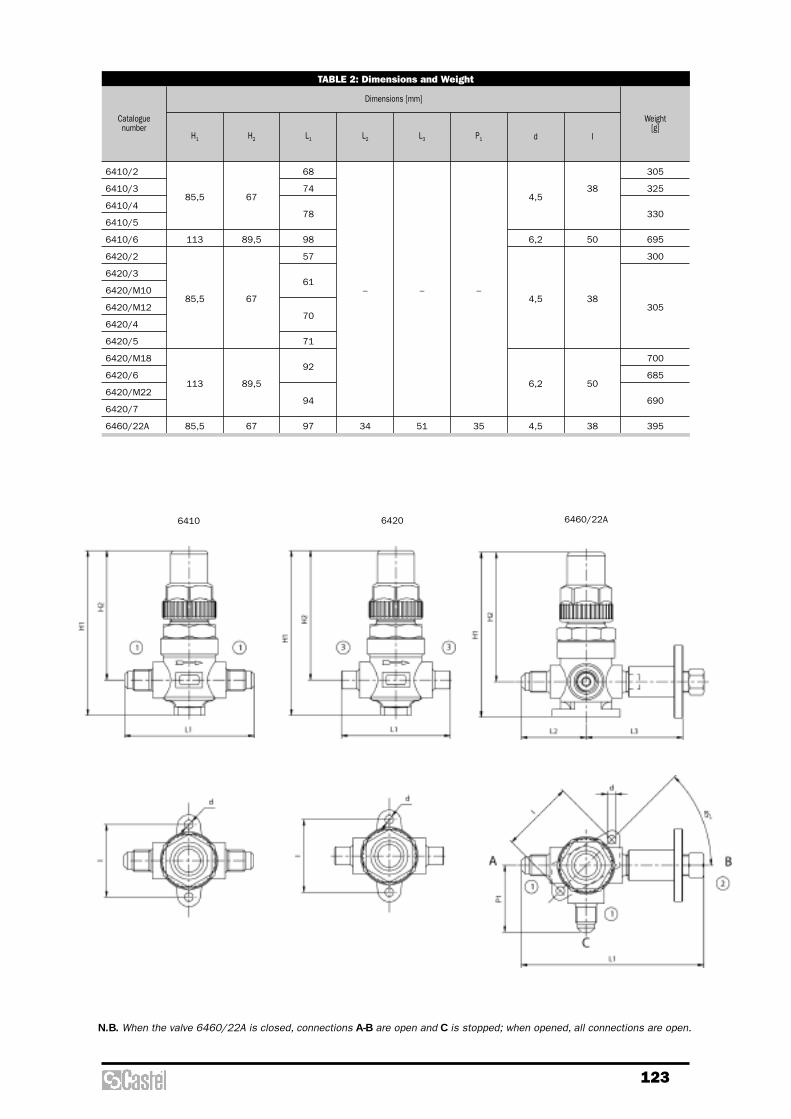
123
TABLE 2: Dimensions and Weight
Cataloguenumber
H1 H2 L1 L2 L3 P1 d I
Dimensions [mm]
Weight [g]
6410/2
6410/3
6410/4
6410/5
6410/6
6420/2
6420/3
6420/M10
6420/M12
6420/4
6420/5
6420/M18
6420/6
6420/M22
6420/7
6460/22A
85,5
113
85,5
113
85,5
67
89,5
67
89,5
67
68
74
78
98
57
61
70
71
92
94
97
–
34
–
51
–
35
4,5
6,2
4,5
6,2
4,5
38
50
38
50
38
305
325
330
695
300
305
700
685
690
395
N.B. When the valve 6460/22A is closed, connections A-B are open and C is stopped; when opened, all connections are open.
6410 6460/22A6420

124
CONSTRUCTION
These valves are available in the following twotypes:– 6512 with straight solder connections;– 6532 with solder angle connections;The main parts of the globe valves are madewith the following materials:– hot forged brass EN 12420 – CW 617N for
body, cover and cap that covers the spindle;– steel, with proper surface protection, for the
spindle;– chloroprene rubber (CR) and aramidic fibers
for gland seal;– metal-rubber laminated for outlet seal
gaskets– P.T.F.E. for seat gaskets.
APPLICATIONS
The globe valves, shown in this chapter, areclassified “Pressure accessories” in thesense of the Pressure Equipment Directive97/23/EC, Article 1, Section 2.1.4 and aresubject of Article 3, Section 1.3 of the sameDirective.They are designed for installation oncommercial refrigerating systems and on civiland industrial conditioning plants, which userefrigerant fluids proper to the Group II (asdefined in Article 9, Section 2.2 of Directive97/23/EC and referred to in Directive67/548/EEC).
GLOBE VALVES
TABLE 1: General Characteristics
Cataloguenumber
KvFactor[m3/h]
–
7/8"
–
1.1/8"
1.3/8"
1.5/8"
–
2.1/8"
–
7/8"
–
1.1/8"
1.3/8"
1.5/8"
–
2.1/8"
22
–
28
–
35
–
42
54
22
–
28
–
35
–
42
54
–
1.1/8"
1.3/8"
1.3/8"
1.5/8"
2"
2"
–
–
1.1/8"
1.3/8"
1.3/8"
1.5/8"
2"
2"
–
28
–
35
35
–
–
–
–
28
–
35
35
–
–
–
–
7,1
8,4
15,0
25,0
40,0
8,2
9,1
18,7
38,0
48,5
-35 +160 45
Art. 3.3
I
Art. 3.3
I
Ø[in.]
Ø[mm]
ODS
Ø[mm]
Ø[in.]
ODM
Connections
min.
TS [°C]
max.
PS[bar]
RiskCategory
according to PED
6512/M22
6512/7
6512/M28
6512/9
6512/11
6512/13
6512/M42
6512/17
6532/M22
6532/7
6532/M28
6532/9
6532/11
6532/13
6532/M42
6532/17

125
TABLE 2: Dimensions and Weight
Cataloguenumber
6512/M22
6512/7
6512/M28
6512/9
6512/11
6512/13
6512/M42
6512/17
6532/M22
6532/7
6532/M28
6532/9
6532/11
6532/13
6532/M42
6532/17
136
166
199
215
147
165
238
28,5
34
37
42,5
44,5
52,5
65
100
118
141
173
80
93
139
–
50
59
86,5
60
68
88
104
60
68
104
94
126
138
94
126
138
1415
1310
2020
3500
5050
1350
1290
1910
4920
4765
H H1 L L1 Q A
Dimensions [mm]
Weight [g]
6512
6532
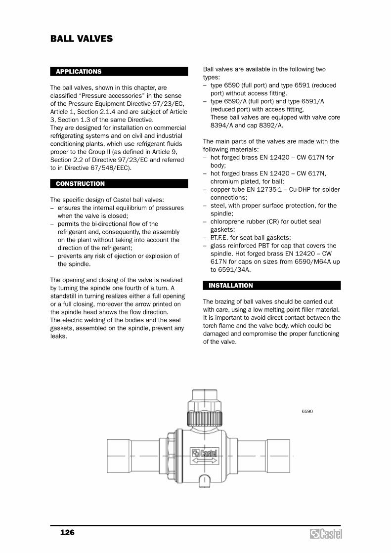
126
BALL VALVES
APPLICATIONS
The ball valves, shown in this chapter, areclassified “Pressure accessories” in the senseof the Pressure Equipment Directive 97/23/EC,Article 1, Section 2.1.4 and are subject of Article3, Section 1.3 of the same Directive.They are designed for installation on commercialrefrigerating systems and on civil and industrialconditioning plants, which use refrigerant fluidsproper to the Group II (as defined in Article 9,Section 2.2 of Directive 97/23/EC and referredto in Directive 67/548/EEC).
CONSTRUCTION
The specific design of Castel ball valves:– ensures the internal equilibrium of pressures
when the valve is closed;– permits the bi-directional flow of the
refrigerant and, consequently, the assemblyon the plant without taking into account thedirection of the refrigerant;
– prevents any risk of ejection or explosion ofthe spindle.
The opening and closing of the valve is realizedby turning the spindle one fourth of a turn. Astandstill in turning realizes either a full openingor a full closing, moreover the arrow printed onthe spindle head shows the flow direction.The electric welding of the bodies and the sealgaskets, assembled on the spindle, prevent anyleaks.
Ball valves are available in the following twotypes:– type 6590 (full port) and type 6591 (reduced
port) without access fitting.– type 6590/A (full port) and type 6591/A
(reduced port) with access fitting. These ball valves are equipped with valve core8394/A and cap 8392/A.
The main parts of the valves are made with thefollowing materials:– hot forged brass EN 12420 – CW 617N for
body;– hot forged brass EN 12420 – CW 617N,
chromium plated, for ball;– copper tube EN 12735-1 – Cu-DHP for solder
connections;– steel, with proper surface protection, for the
spindle;– chloroprene rubber (CR) for outlet seal
gaskets;– P.T.F.E. for seat ball gaskets;– glass reinforced PBT for cap that covers the
spindle. Hot forged brass EN 12420 – CW617N for caps on sizes from 6590/M64A upto 6591/34A.
INSTALLATION
The brazing of ball valves should be carried outwith care, using a low melting point filler material.It is important to avoid direct contact between thetorch flame and the valve body, which could bedamaged and compromise the proper functioningof the valve.
6590

127
TABLE 1: General Characteristics
Withoutaccessfitting
Withaccessfitting
Catalogue number
KvFactor[m3/h]
–
1/4"
3/8"
–
–
1/2"
5/8"
–
5/8"
–
3/4"
7/8"
7/8"
–
1.1/8"
–
1.1/8"
1.3/8"
1.3/8"
1.5/8"
–
1.5/8"
–
2.1/8"
2.1/8"
–
2.5/8"
–
2.5/8"
3"
3.1/8"
3.1/8"
3.1/2"
3.5/8"
4.1/8"
4.1/4"
6
–
–
10
12
–
16
15
16
18
–
22
22
28
–
28
–
35
35
–
42
–
42
54
54
64
–
64
–
80
89
–
105
108
10
15
19
25
32
38
50
65
80
0,8
3
5
14,5
24
40
68
100
178
293
430
-40 +150
45
42
Art. 3.3
I
Ø[in.]
Ø[mm]
Ball PortØ [mm]
ODS
Connections
min.
TS [°C]
max.
PS[bar]
RiskCategory
according to PED
6590/M6
6590/2
6590/3
6590/M10
6590/M12
6590/4
6591/5
6590/M15
6590/5
6590/M18
6590/6
6591/7
6590/7
6591/M28
6591/9
6590/M28
6590/9
6591/11
6590/11
6591/13
6591/M42
6590/13
6590/M42
6591/17
6590/17
6591/M64
6591/21
–
–
6590/3A
6590/M10A
6590/M12A
6590/4A
–
6590/M15A
6590/5A
6590/M18A
6590/6A
–
6590/7A
–
6590/M28A
6590/9A
–
6590/11A
–
6590/13A
6590/M42A
–
6590/17A
6591/M64A
6591/21A
6590/M64A
6590/21A
6591/24A
6591/25A
6590/25A
6591/28A
6591/29A
6591/33A
6591/34A
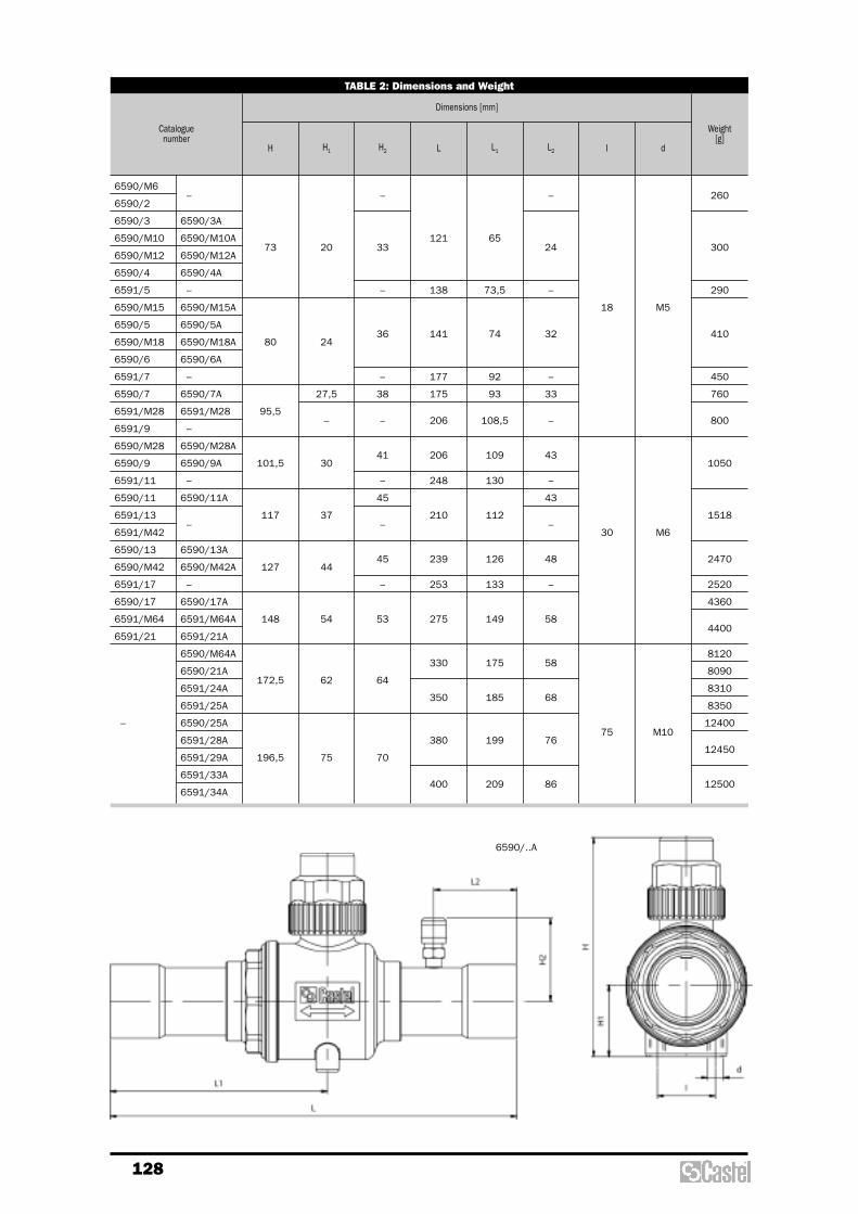
128
TABLE 2: Dimensions and Weight
Cataloguenumber
H H1 H2 L L1 L2 I d
Dimensions [mm]
Weight[g]
–
6590/3A
6590/M10A
6590/M12A
6590/4A
–
6590/M15A
6590/5A
6590/M18A
6590/6A
–
6590/7A
6591/M28
–
6590/M28A
6590/9A
–
6590/11A
–
6590/13A
6590/M42A
–
6590/17A
6591/M64A
6591/21A
6590/M64A
6590/21A
6591/24A
6591/25A
6590/25A
6591/28A
6591/29A
6591/33A
6591/34A
6590/M6
6590/2
6590/3
6590/M10
6590/M12
6590/4
6591/5
6590/M15
6590/5
6590/M18
6590/6
6591/7
6590/7
6591/M28
6591/9
6590/M28
6590/9
6591/11
6590/11
6591/13
6591/M42
6590/13
6590/M42
6591/17
6590/17
6591/M64
6591/21
–
73
80
95,5
101,5
117
127
148
172,5
196,5
20
24
27,5
–
30
37
44
54
62
75
–
33
–
36
–
38
–
41
–
45
–
45
–
53
64
70
121
138
141
177
175
206
206
248
210
239
253
275
330
350
380
400
65
73,5
74
92
93
108,5
109
130
112
126
133
149
175
185
199
209
–
24
–
32
–
33
–
43
–
43
–
48
–
58
58
68
76
86
18
30
75
M5
M6
M10
260
300
290
410
450
760
800
1050
1518
2470
2520
4360
4400
8120
8090
8310
8350
12400
12450
12500
6590/..A

129
CONSTRUCTION
The valves are equipped with:– a little flange for fixing the valve to the
control panel;– a SAE-Flare connection for joining it to the
copper tube;– an NPT (type 8320) or a swivel SAE FLare
(8321) connection for mounting the gauge.The main parts of this valve are made with thefollowing materials:– Hot forged brass EN 12420 – CW 617N for
body;– Steel, with proper surface protection, for the
spindle;– Chloroprene rubber (CR) and aramidic fibers
for gland seal;– Glass reinforced PBT for cap that covers the
spindle.
GAUGE MOUNTING VALVES
TABLE 1: General Characteristics
Cataloguenumber
1/4"
1/4"
1/4"
1/8"
1/4"
–
19
37
40
-60 +130 45 Art. 3.3
H1SAEFlare NPT
–
–
1/4" f
SAEFlare
Connections Dimensions [mm]
min.
TS [°C]
max.
PS[bar]
RiskCategory
according to PED
8320/21
8320/22
8321/22
83
L1
35
L2
17
L3
140
186
Weight[g]
APPLICATIONS
The valves, shown in this chapter, are classified“Pressure accessories” in the sense of thePressure Equipment Directive 97/23/EC,Article 1, Section 2.1.4 and are subject ofArticle 3, Section 1.3 of the same Directive.They are designed for installation oncommercial refrigerating systems and on civiland industrial conditioning plants, which userefrigerant fluids proper to the Group II (asdefined in Article 9, Section 2.2 of Directive97/23/EC and referred to in Directive67/548/EEC). They are used for mounting andintercepting the gauges on control panels.
8320
8321
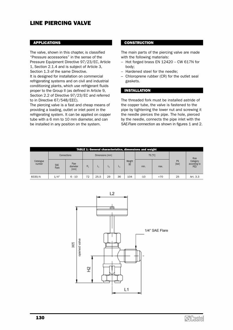
130
CONSTRUCTION
The main parts of the piercing valve are madewith the following materials:– Hot forged brass EN 12420 – CW 617N for
body;– Hardened steel for the needle;– Chloroprene rubber (CR) for the outlet seal
gaskets.
INSTALLATION
The threaded fork must be installed astride ofthe copper tube, the valve is fastened to thepipe by tightening the lower nut and screwing itthe needle pierces the pipe. The hole, piercedby the needle, connects the pipe inlet with theSAE-Flare connection as shown in figures 1 and 2.
APPLICATIONS
The valve, shown in this chapter, is classified“Pressure accessories” in the sense of thePressure Equipment Directive 97/23/EC, Article1, Section 2.1.4 and is subject of Article 3,Section 1.3 of the same Directive.It is designed for installation on commercialrefrigerating systems and on civil and industrialconditioning plants, which use refrigerant fluidsproper to the Group II (as defined in Article 9,Section 2.2 of Directive 97/23/EC and referredto in Directive 67/548/EEC).The piercing valve is a fast and cheap means ofproviding a loading, outlet or inlet point in therefrigerating system. It can be applied on coppertube with a 6 mm to 10 mm diameter, and canbe installed in any position on the system.
LINE PIERCING VALVE
TABLE 1: General characteristics, dimensions and weight
Cataloguenumber
1/4" 6 - 10 72 -10 +70 25 Art. 3.3
H1SAEFlare
Pipe diameter
[mm]
Connections Dimensions [mm]
min.
TS [°C]
max.
PS[bar]
RiskCategory
according toPED
8330/A 25,5
L1
29
L2
36
L3
104
Weight[g]
open
ed v
alve
Threaded brass fittings

132
All straight fittings, from series 7110 to series7170, and all the plug, from series 7510 toseries 7520, are machined by brass bar EN12164 – CW 614N.Seal caps series 7560 and gaskets series 7580 are made with copper Cu – ETP UNI 5649.The main parts of the flanges joints are madewith the following materials:– hot forged brass EN 12420 – CW 617N for
bushes and flanges;– aramidic fibers for seal gasket of the
flanges.
APPLICATIONS
All the fittings, shown in this chapter, areexcluded from the scope of Directive97/23/EC, as specified in the Guidelines 1/8and 1/9, because they are piping components.They are designed for installation oncommercial refrigerating systems and on civiland industrial conditioning plants, which userefrigerant fluids proper to the Group II (asdefined in Article 9, Section 2.2 of Directive97/23/EC and referred to in Directive67/548/EEC).
OPERATION
The sealing system between the end of a maleconnection and a nut series 7010, 7020 and7030 requires a special flaring of the end ofcopper tube, the so-called flared connection.The sealing system between the end of a maleconnection and a Flare-ODS adapter allowsavoiding the flaring process on copper tube end(national laws of some European countriesdon’t accept this operation) because the tubeend is brazed into the solder connection of theadapter. We wish to remember to our customers thatthey may assure no leakage of the maleconnection/adapter system only interposing thecopper gasket 7580, supplied with the sameadapter.Flange joints 7630 consist of two brass bushesfor brazing to the copper tubes. When the fourflange screws are tightened, a gasket, putbetween the two bushes, assures the seal offlanged joints.
CONSTRUCTION
All nuts, from series 7010 to series 7050, andall the elbows, TEE and cross fittings, fromseries 7210 to series 7410, are manufacturedwith hot forged brass EN 12420 – CW 617N.
THREADED BRASS FITTINGS

133
TABLE 1: General Characteristics
Cataloguenumber
InternationalReference
SAE Flare Ø
[in]Ø
[mm]
PS [bar]
Ø D L Ch
Copper pipe Dimensions [mm]Wrenchtorque
min / max[Nm]
Weight [g]
7010/22
7010/33
7010/44
7010/55
7010/66
7010/77
7010/88
NS4–4
NS4–6
NS4–8
NS4–10
NS4–12
NS4–14
NS4–16
1/4"
3/8"
1/2"
5/8"
3/4"
7/8"
1"
1/4"
3/8"
1/2"
5/8"
3/4"
7/8"
1"
6
–
–
16
–
22
–
45
6,5
9,7
13
16,2
19,4
22,5
25,6
15,5
19,5
22,5
25
29,5
36,5
36,5
17
22
25
28
33
41
11 / 14
20 / 25
34 / 47
54 / 75
68 / 71
90 /120
120 / 150
19
38
49
64
97
186
153
SAE Flare nuts (inch tubing)
7020/20
7020/X02
N5–4
CAP NUT
N5-5
CAP NUT
1/4"
5/16"
blind blind 45 –
15,5
15
17
15
11 / 14
8,5 / 11,5
20
14
SAE Flare cap nuts
7020/32
7020/43
7020/54
7020/65
7020/87
NRS4–64
NRS4–86
NRS4–108
NRS4–1210
NRS4–1614
3/8"
1/2"
5/8"
3/4"
1"
1/4"
3/8"
1/2"
5/8"
7/8"
6
–
–
16
22
45
6,5
9,7
13
16,2
22,5
19,5
22,5
25
29,5
36,5
22
25
28
33
41
20 / 25
34 / 47
54 / 75
68 / 71
120 / 150
38
53
69
104
160
SAE Flare reducing nuts (inch tubing)
7030/3M8
7030/3M10
7030/4M10
7030/4M12
7030/4M14
7030/5M12
7030/5M14
7030/6M14
7030/6M18
–
3/8"
1/2"
5/8"
3/4"
–
8
10
10
12
14
12
14
14
18
45
8,3
10,3
10,3
12,3
14,3
12,3
14,3
14,3
18,3
19,5
22,5
25
29,5
22
25
28
33
20 / 25
34 / 47
54 / 75
68 / 71
37
36
53
50
47
70
68
106
98
SAE Flare nuts (metric tubing)
7050/2
7050/3
7050/4
7050/5
US4–4
US4–6
US4–8
US4–10
1/4"
3/8"
1/2"
5/8"
45 –
32
40
46
51
17
22
25
28
11 / 14
20 / 25
34 / 47
54 / 75
39
78
105
140
SAE Flare twin nuts
– –

134
TABLE 2: General Characteristics
Cataloguenumber
InternationalReference
SAE Flare NPT
PS [bar]
L Ch
Connections Dimensions [mm]
Weight[g]
7110/2
7110/3
7110/4
7110/5
7110/6
7110/8
U2–4
U2–6
U2–8
U2–10
U2–12
U2–16
1/4"
3/8"
1/2"
5/8"
3/4"
1"
– 45
38
44
50
58
63
72
12
17
20
23
27
36
23
46
73
113
164
304
SAE Flare unions
1/4" x 3/8"
1/4" x 1/2"
3/8" x 1/2"
3/8" x 5/8"
1/2" x 5/8"
5/8" x 3/4"
– 45
42
45
48
52
54
61,5
17
20
23
23
27
38
58
66
89
98
170
Reducing SAE Flare unions
7130/2
7130/3
7130/4
7130/6
7130/8
U1–4B
U1–6C
U1–8D
U1–12F
U1–16H
1/4"
3/8"
1/2"
3/4"
1"
1/4"
3/8"
1/2"
3/4"
1"
45
38,1
41,2
49,8
57,6
68
14
17
22
27
36
32
48
92
152
277
SAE Flare / NPT unions
7140/21
7140/32
7140/43
7140/54
U1–4A
U1–6B
U1–8C
U1–10D
1/4"
3/8"
1/2"
5/8"
1/8"
1/4"
3/8"
1/2"
45
32,9
41,1
45,2
53,8
12
17
20
23
20
39
64
102
SAE Flare / NPT reducing unions
Available on request
Until exhaustion of the stockE
R
7120/23
7120/24
7120/34
7120/35
7120/45
7120/56
UR2–64
UR2–84
UR2–86
UR2-106
UR2–108
UR2-1210
E
R
R
R

135
TABLE 3: General Characteristics
Cataloguenumber
InternationalReference SAE Flare ODS
m fNPT GAS
Ø[in.]
Ø[mm]
PS [bar]
L Ch
Connections Dimensions [mm]
Weight [g]
7150/21
7150/32
7150/43
7150/54
7150/64
7150/65
U3–4A
UR3–46
UR3–68
UR3–810
UR3–812
UR3–1012
1/4"
3/8"
1/2"
5/8"
3/4"
3/4"
–
1/4"
3/8"
1/2"
1/2"
5/8"
1/8" f
–– – – 45
29
33
38
45
46,5
49,5
14
17
22
25
27
30
21
38
66
99
132
157
Male / female reducing unions (reduced female)
7150/23
7150/24
7150/34
7150/45
7150/46
7150/56
UR3–64
UR3–84
UR3–86
UR3–108
UR3–128
UR3–1210
1/4"
1/4"
3/8"
1/2"
1/2"
5/8"
3/8"
1/2"
1/2"
5/8"
3/4"
3/4"
– – – – 45
33
36
39
44
45
49
22
25
30
34
49
66
74
127
140
150
Male / female reducing unions (reduced male)
7154/2
7156/2
–
1/4"
1/4"
20 – 14 left thread, female
W 21,8 – 14 right thread, female
45 29
25
27
46
52
Cylinder adaptors
7160/2
7160/3
7160/4
R –
1/4"
3/8"
1/2"
1/4"
3/8"
1/2"
– – – – 45
30,5
36
41
17
22
25
31
57
84
Male / female unions
7164/2
7166/2
–
1/4"
–
–
1/4"
–
G1/4"
f
G1/4"
m
– – 45
32,5
32
20
17
45
25
Unions SAE Flare to BSP
7170/22
7170/2M8
7170/33
7170/3M10
7170/44
7170/4M12
7170/55
7170/6M18
US3–44
–
US3–66
–
US3–88
–
US3–1010
–
1/4"
3/8"
1/2"
5/8"
3/4"
– – –
1/4"
–
3/8"
–
1/2"
–
5/8"
–
–
8
–
10
–
12
16
18
45
26,5
33
35
42
45,5
12
17
20
23
27
17
39
55
82
123
Male SAE Flare / solder unions
Available on requestR

136
TABLE 4: General Characteristics
Item
pos
ition
Cataloguenumber SAE
Flare
ODS
Ø[in.]
Ø[mm]
PS [bar]
L1 L2 L3 L4 Ch
Connections Dimensions [mm]
Weight[g]
Wrenchtorque
min/max[Nm]
1
2
3
1
2
3
1
2
3
1
2
3
1
2
3
1
2
3
1
2
3
1
2
3
1
2
3
9900/X58
9900/X62
7580/2
9900/X58
9900/X70
7580/2
9900/X59
9900/X63
7580/3
9900/X59
9900/X71
7580/3
9900/X60
9900/X64
7580/4
9900/X60
9900/X72
7580/4
9900/X61
9900/X65
7580/5
9900/X68
9900/X69
7580/6
9900/X68
9900/X77
7580/6
1/4"
1/4"
3/8"
3/8"
1/2"
1/2"
5/8"
3/4"
3/4"
1/4"
–
3/8"
–
1/2"
–
5/8"
3/4"
–
–
6
–
10
–
12
16
–
18
45
–
21
–
21
–
23,5
–
23,5
–
26
–
–
26
–
27,5
–
30
–
30
–
3,5
–
3,5
–
4
–
4
–
4,5
–
–
4,5
–
5
–
5
–
5
16
–
–
16
–
–
18,5
–
–
18,5
–
–
21
–
–
21
–
–
22,5
–
–
25
–
–
25
–
–
12,5
–
12,5
–
14,7
–
14,7
–
17
–
–
17
–
18
–
20
–
20
–
17
–
17
–
22
–
22
–
27
–
–
27
–
30
–
36
–
36
–
67
83
114
130
207
226
271
404
455
11/14
–
11/14
–
20/25
–
20/25
–
34/47
–
34/47
–
54/75
–
68/71
–
68/71
–
Flare - ODS adapters
POS. 1
POS. 2
POS. 3
Flare/ODS fitting
Nut Connection Copper seal
Copper pipe SAE/Flare connection

137
TABLE 5: General Characteristics
Cataloguenumber
InternationalReference SAE Flare
m fNPT
PS [bar]
H L
Connections Dimensions [mm]
Weight [g]
7210/2
7210/3
7210/4
7210/5
7210/6
E2–4
E2–6
E2–8
E2–10
E2–12
1/4"
3/8"
1/2"
5/8"
3/4"
– – 45
24,5
29,5
32,5
36
42,5
24,5
29,5
32,5
36
42,5
26
49
83
116
192
SAE Flare elbows
7220/2
7220/3
7220/4
7220/6
E1–4B
E1–6C
E1–8D
E1–12F
1/4"
3/8"
1/2"
3/4"
–
1/4"
3/8"
1/2"
3/4"
45
26
29,5
32,5
42,5
24
28,5
32
39,5
33
54
91
183
SAE Flare / NPT elbows
7230/21
7230/32
7230/43
7230/54
E1–4A
E1–6B
E1–8C
E1–10D
1/4"
3/8"
1/2"
5/8"
–
1/8"
1/4"
3/8"
1/2"
45
24,5
29,5
32,5
36
23,5
29,5
31
35
25
46
75
114
SAE Flare / reduced NPT elbows
7240/2
7240/3
7240/4
–
1/4"
3/8"
1/2"
1/4"
3/8"
1/2"
– 45
28,5
32
39,5
28
31
38
56
84
198
Male / female SAE Flare elbows

138
TABLE 6: General Characteristics
Cataloguenumber
InternationalReference SAE Flare
(1) (2) (3) (4)
NPT(3)
PS [bar]
H L
Connections Dimensions [mm]
Weight [g]
7310/2
7310/3
7310/4
7310/5
7310/6
T2–4
T2–6
T2–8
T2–10
T2–12
1/4"
3/8"
1/2"
5/8"
3/4"
1/4"
3/8"
1/2"
5/8"
3/4"
1/4"
3/8"
1/2"
5/8"
3/4"
– – 45
23,5
29
31,5
36
41,5
47
58
63
72
83
32
69
97
153
235
SAE Flare TEE
7320/223
7320/334
7320/445
7320/556
TR2–46
TR2–68
TR2–810
TR2–1012
1/4"
3/8"
1/2"
5/8"
1/4"
3/8"
1/2"
5/8"
3/8"
1/2"
5/8"
3/4"
– – 45
29
32,5
38
41,5
56
63
72
83
77
95
153
228
SAE Flare reducing TEE (reduced side connections)
7320/332
7320/443
7320/554
7320/665
TR2–64
TR2–86
TR2–108
TR2–1210
3/8"
1/2"
5/8"
3/4"
3/8"
1/2"
5/8"
3/4"
1/4"
3/8"
1/2"
5/8"
– – 45
28
32,5
38
41,5
58
63
72
83
77
101
158
220
SAE Flare reducing TEE (reduced central connection)
7330/221
7330/222
T1–4A
T1–4B
1/4"
1/4"
1/4"
1/4"
– –
1/8"
1/4"
45
21
24
47
51
56
198
SAE Flare / NPT TEE (taper central connection)
7340/222 T6–4 1/4" 1/4" 1/4" – – 45 27,5 56 78
Male / female SAE Flare (female central connection)
H
L
H
L
H
L
7330/221
7340/222
7410/2
7410/2 C1–4 1/4" 1/4" 1/4" 1/4" – 45 52 52 55
SAE Flare cross
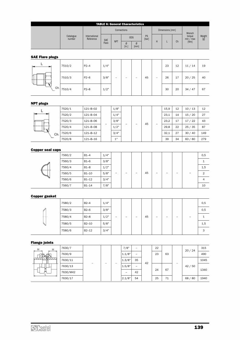
139
TABLE 6: General Characteristics
Cataloguenumber
InternationalReference SAE
Flare NPTODS
Ø[in.]
Ø[mm]
PS [bar]
H L Ch
Connections Dimensions [mm]Wrench torque
min / max[Nm]
Weight[g]
7520/1
7520/2
7520/3
7520/4
7520/6
7520/8
121–B–02
121–B–04
121–B–06
121–B–08
121–B–12
121–B–16
–
1/8"
1/4"
3/8"
1/2"
3/4"
1"
– – 45 –
15,9
23,1
23,2
29,8
32,1
39
12
14
17
22
27
34
10 / 13
15 / 20
17 / 22
25 / 35
30 / 40
60 / 80
12
27
43
87
149
279
NPT plugs
7510/2
7510/3
7510/4
P2–4
P2–6
P2–8
1/4"
3/8"
1/2"
– – – 45 –
23
26
30
12
17
20
11 / 14
20 / 25
34 / 47
19
40
67
SAE Flare plugs
7560/2
7560/3
7560/4
7560/5
7560/6
7560/7
B1–4
B1–6
B1–8
B1–10
B1–12
B1–14
1/4"
3/8"
1/2"
5/8"
3/4"
7/8"
– – – 45 – – – –
0,5
1
1,5
2
4
10
Copper seal caps
L
H H
Ch
Ch
7580/2
7580/3
7580/4
7580/5
7580/6
B2–4
B2–6
B2–8
B2–10
B2–12
1/4"
3/8"
1/2"
5/8"
3/4"
– – – 45 – – – –
0,5
0,5
1
1,5
3
Copper gasket
7630/7
7630/9
7630/11
7630/13
7630/M42
7630/17
– – –
7/8"
1.1/8"
1.3/8"
1.5/8"
–
2.1/8"
–
–
35
–
42
54
42
22
23
24
25
63
67
71
–
20 / 24
42 / 50
68 / 80
315
490
1045
1340
1940
Flange joints


Copper braze - joint pressure fittings

142
dimensions:– 7832 Tees and reducing teesReinforced series 79 show the followingselection of copper braze-joint fittings, with ODS/ IDS millimeters connections, limited to somedimensions:– 7900 Female to female couplings– 7902 Female to female reducing
couplings– 7903 Male to female reducing couplings– 7916 45° female to female elbows– 7917 45° male to female elbows– 7918 90° female to female elbows –
long radius– 7919 90° male to female elbows –
long radius– 7932 Tees and reducing tees
CONSTRUCTION
Dimensions and tolerances of the ODS / IDSconnections ends in copper braze-joint fittingsseries 77, 78 and 79 are in compliance withthe EN 1254-1 : 1998 Standard.All copper braze-joint fittings series 77, 78 and79 are made of seamless copper tube EN12735-2 – CW024A, soft annealed.Technical characteristics of copper fittingsseries 77 and 78, depending on tube nominaldiameters, are given in table 1, while technicalcharacteristics of copper fittings series 79,always depending on nominal diameters, aregiven in table 2.Copper braze-joint fittings series 77, 78 and79, if submitted to ambient-temperature bursttest, guarantee a pressure strength at leastequal to 3 x PS (30 °C rated working-pressureas shown in tables 1 and 2) according to ASMEB16.50 : 2001 Standard.
APPLICATIONS
All the fittings, shown in this chapter, areexcluded from the scope of Directive97/23/EC, as specified in the Guidelines 1/8and 1/9, because they are piping components.They are designed for installation oncommercial refrigerating systems and on civiland industrial conditioning plants, made ofseamless copper tube specified in EN 12735-1: 2001 Standard, which use refrigerant fluidsproper to the Group II (as defined in Article 9,Section 2.2 of Directive 97/23/EC and referredto in Directive 67/548/EEC).
PRODUCTS RANGE
Series 77 show the following selection ofcopper braze-joint fittings, with ODS / IDSmillimeters connections, practically in alldiameter dimensions:– 7700 Female to female couplings– 7702 Female to female reducing
couplings– 7703 Male to female reducing couplings– 7708 90° female to female elbows –
short radius– 7709 90° male to female elbows –
short radius– 7716 45° female to female elbows– 7717 45° male to female elbows– 7718 90° female to female elbows –
long radius– 7719 90° male to female elbows –
long radius– 7732 Tees and reducing tees
Series 78 show the following selection ofcopper braze-joint fittings, with ODS / IDS inchconnections, limited to few diameter
COPPER BRAZE-JOINT PRESSURE FITTINGS

143
INSTALLATION
The internal working pressure-temperaturerating for a copper fitting, is dependent upon,not only fitting strength, but also the adoptedjoining process and the used filler metal. Theworking pressure-temperature values given intables 1 and 2 are referred to a brazingprocess, performed in accordance with thesound engineering practice.We wish to remember the definition of brazingprocess, given in EN 13133 : 2000 Standard.“The process of joining generally applied to thejoining of materials by a heating process duringwhich the parent materials do not melt and thefiller metal is drawn into the joint by capillaryaction. It is generally applicable to joiningsystems where the filler metal melts at 450 °Cor above”.In actual practice brazing is done attemperatures ranging from 630 to 820 °C andthere are two general types of brazing fillermetals, normally used for joining copper tube:– Copper – Phosphorus alloys (the so called B-
CuP), proper to CP Class of EN 1044 : 1999Standard, that are normally used withoutfluxes;
– Silver alloys (the so called B-Ag), proper toAG Class of EN 1044 : 1999, that must beused with their specific fluxes.
TABLE 1
Tube Nominal Diameter
6
–
8
–
10
12
–
14
15
16
18
22
–
28
–
35
–
42
54
64
–
67
76
–
80
89
106
–
1/4"
–
3/8"
–
–
1/2"
–
–
5/8"
–
7/8"
1"
–
1.1/8"
1.3/8"
1.5/8"
–
2.1/8"
–
2.5/8"
–
–
3.1/8"
–
3.1/2"
–
90
90
70
60
60
50
50
45
45
45
40
40
35
30
30
30
25
25
20
20
20
20
18
18
18
18
15
72
72
56
48
48
40
40
36
36
36
32
32
28
24
24
24
20
20
16
16
16
16
14
14
14
12
12
63
63
49
42
42
35
35
32
32
32
28
28
24
21
21
21
18
18
14
14
14
14
13
13
13
11
11
[mm] [in.] -40 / +30 °C +95 °C +150 °C
Working Pressure PS [bar],depending on temperature
TABLE 2
Tube Nominal Diameter
22
–
28
–
35
–
42
54
7/8”
1”
–
1.1/8”
1.3/8”
1.5/8”
–
2.1/8”
60
55
50
50
50
40
40
35
80
73
67
67
67
53
53
47
50
45
40
40
40
35
35
30
[mm] [in.] (1) (2) (1)
67
60
53
53
53
47
47
40
45
41
37
37
37
30
30
26
60
55
49
49
49
40
40
35
(2) (1)
-40 /+ 30 °C +95 °C +150 °C
(2)
Working Pressure PS [bar], depending on temperature
(1) PS values listed in this column are referred to a safety coefficient 4, according to ASME B16.50 : 2001 Standard
(2) PS values listed in this column are referred to a safety cefficient 3, minimum value warranted by Castel for all its products
Note: working pressure shown in this table are incomparison with rated working pressures established inASME B16.50 : 2001 Standard.

144
TABLE 3: General Characteristics
InternationalReference
Cataloguenumber IDS
Ø[mm]
ODSØ
[mm]
Weight[g] Note
Connections
7700/M6
7700/M8
7700/M10
7700/M12
7700/M14
7700/M16
7700/M18
7700/M22
7700/M28
7700/M35
7700/M42
7700/M54
7700/M76
7700/M89
5270/6
5270/8
5270/10
5270/12
5270/14
5270/16
5270/18
5270/22
5270/28
5270/35
5270/42
5270/54
5270/76
5270/89
– –
6
8
10
12
14
16
18
22
28
35
42
54
76
89
6
8
10
12
14
16
18
22
28
35
42
54
76
89
2
3
4
5
8
8
13
20
39
71
89
138
220
350
Female to female couplings (metric tubing)
7702/M10.6
7702/M10.8
7702/M12.8
7702/M12.10
7702/M14.10
7702/M14.12
7702/M16.10
7702/M16.12
7702/M16.14
7702/M18.12
7702/M18.16
7702/M22.12
7702/M22.14
7702/M22.16
7702/M22.18
7702/M28.12
7702/M28.18
7702/M28.22
7702/M35.22
7702/M35.28
7702/M42.28
7702/M42.35
7702/M54.35
7702/M54.42
7702/M67.54
7702/M76.54
5240/10.6
5240/10.8
5240/12.8
5240/12.10
5240/14.10
5240/14.12
5240/16.10
5240/16.12
5240/16.14
5240/18.12
5240/18.16
5240/22.12
5240/22.14
5240/22.16
5240/22.18
5240/28.12
5240/28.18
5240/28.22
5240/35.22
5240/35.28
5240/42.28
5240/42.35
5240/54.35
5240/54.42
5240/67.54
5240/76.54
– –
10
10
12
12
14
14
16
16
16
18
18
22
22
22
22
28
28
28
35
35
42
42
54
54
67
76
6
8
8
10
10
12
10
12
14
12
16
12
14
16
18
12
18
22
22
28
28
35
35
42
54
54
3
6
6
8
9
9
12
9
11
12
13
22
19
23
23
34
29
33
56
56
66
88
166
160
246
314
Female to female reducing couplings (metric tubing)

145
TABLE 4: General Characteristics
InternationalReference
Cataloguenumber IDS
Ø[mm]
ODSØ
[mm]
Weight [g] Note
Connections
7703/M8.6
7703/M10.6
7703/M10.8
7703/M12.6
7703/M12.8
7703/M12.10
7703/M14.10
7703/M14.12
7703/M16.10
7703/M16.12
7703/M16.14
7703/M18.10
7703/M18.12
7703/M18.14
7703/M18.16
7703/M22.12
7703/M22.14
7703/M22.16
7703/M22.18
7703/M28.12
7703/M28.14
7703/M28.16
7703/M28.18
7703/M28.22
7703/M35.18
7703/M35.22
7703/M35.28
7703/M42.22
7703/M42.28
7703/M42.35
7703/M54.28
7703/M54.42
7703/M67.42
7703/M67.54
7703/M76.42
7703/M80.42
7703/M106.54
5243/8.6
5243/10.6
5243/10.8
5243/12.6
5243/12.8
5243/12.10
5243/14.10
5243/14.12
5243/16.10
5243/16.12
5243/16.14
5243/18.10
5243/18.12
5243/18.14
5243/18.16
5243/22.12
5243/22.14
5243/22.16
5243/22.18
5243/28.12
5243/28.14
5243/28.16
5243/28.18
5243/28.22
5243/35.18
5243/35.22
5243/35.28
5243/42.22
5243/42.28
5243/42.35
5243/54.28
5243/54.42
5243/67.42
5243/67.54
5243/76.42
5243/80.42
5243/106.54
8
10
10
12
12
12
14
14
16
16
16
18
18
18
18
22
22
22
22
28
28
28
28
28
35
35
35
42
42
42
54
54
67
67
76
80
106
– –
6
6
8
6
8
10
10
12
10
12
14
10
12
14
16
12
14
16
18
12
14
16
18
22
18
22
28
22
28
35
28
42
42
54
42
42
54
2
3
3
3
6
4
8
5
9
9
8
12
9
11
8
23
20
20
21
32
31
33
29
32
50
65
50
90
102
93
125
146
197
246
270
306
784
= 7700/M6
= 7700/M8
= 7702/M10.6
= 7702/M10.8
= 7700/M10
= 7702/M12.10
= 7700/M12
= 7702/M14.10
= 7702/M14.12
= 7700/M14
= 7702/M16.10
= 7702/M16.12
= 7702/M16.14
= 7700/M16
Male to female reducing couplings (metric tubing)
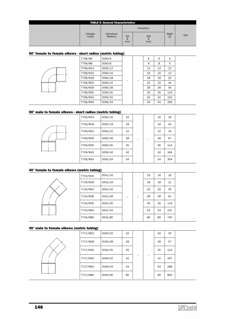
146
TABLE 5: General Characteristics
InternationalReference
Cataloguenumber IDS
Ø[mm]
ODSØ
[mm]
Weight [g] Note
Connections
7708/M6
7708/M8
7708/M14
7708/M16
7708/M18
7708/M22
7708/M28
7708/M35
7708/M42
7708/M54
5090/6
5090/8
5090/14
5090/16
5090/18
5090/22
5090/28
5090/35
5090/42
5090/54
– –
6
8
14
16
18
22
28
35
42
54
6
8
14
16
18
22
28
35
42
54
4
5
12
13
22
34
56
119
163
298
90° female to female elbows - short radius (metric tubing)
7709/M16
7709/M18
7709/M22
7709/M28
7709/M35
7709/M42
7709/M54
5092/16
5092/18
5092/22
5092/28
5092/35
5092/42
5092/54
16
18
22
28
35
42
54
– –
16
18
22
28
35
42
54
18
26
34
67
114
184
304
90° male to female elbows - short radius (metric tubing)
7716/M16
7716/M18
7716/M22
7716/M28
7716/M35
7716/M54
7716/M80
5041/16
5041/18
5041/22
5041/28
5041/35
5041/54
5041/80
– –
16
18
22
28
35
54
80
16
18
22
28
35
54
80
16
21
35
61
119
231
740
45° female to female elbows (metric tubing)
7717/M22
7717/M28
7717/M35
7717/M42
7717/M54
7717/M80
5040/22
5040/28
5040/35
5040/42
5040/54
5040/80
22
28
35
42
54
80
– –
22
28
35
42
54
80
33
57
124
167
288
800
45° male to female elbows (metric tubing)

147
TABLE 6: General Characteristics
InternationalReference
Cataloguenumber IDS
Ø[mm]
ODSØ
[mm]
Weight [g] Note
Connections
7718/M10
7718/M12
7718/M14
7718/M16
7718/M18
7718/M22
7718/M28
7718/M35
7718/M42
7718/M54
7718/M64
7718/M67
7718/M76
7718/M80
7718/M89
5002/10
5002/12
5002/14
5002/16
5002/18
5002/22
5002/28
5002/35
5002/42
5002/54
5002/64
5002/67
5002/76
5002/80
5002/89
– –
10
12
14
16
18
22
28
35
42
54
64
67
76
80
89
10
12
14
16
18
22
28
35
42
54
64
67
76
80
89
7
11
15
20
29
46
79
146
216
353
420
505
880
1340
1670
90° female to female elbows - long radius (metric tubing)
7719/M12
7719/M14
7719/M16
7719/M18
7719/M22
7719/M28
7719/M35
7719/M42
7719/M54
7719/M64
7719/M67
7719/M76
7719/M80
5001/12
5001/14
5001/16
5001/18
5001/22
5001/28
5001/35
5001/42
5001/54
5001/64
5001/67
5001/76
5001/80
12
14
16
18
22
28
35
42
54
64
67
76
80
– –
12
14
16
18
22
28
35
42
54
64
67
76
80
11
16
20
30
47
86
144
210
390
470
550
915
1006
90° male to female elbows - long radius (metric tubing)

148
TABLE 7: General Characteristics
InternationalReference
Cataloguenumber IDS
Ø[mm]
ODSØ
[mm]
Weight[g] Note
Connections
7732/M6
7732/M8
7732/M10
7732/M12
7732/M14
7732/M16
7732/M18
7732/M22
7732/M28
7732/M35
7732/M42
7732/M54
7732/M64
7732/M67
7732/M80
5130/6
5130/8
5130/10
5130/12
5130/14
5130/16
5130/18
5130/22
5130/28
5130/35
5130/42
5130/54
5130/64
5130/67
5130/80
–
6
8
10
12
14
16
18
22
28
35
42
54
64
67
80
6
8
10
12
14
16
18
22
28
35
42
54
64
67
80
6
8
10
12
14
16
18
22
28
35
42
54
64
67
80
5
7
17
14
22
25
36
59
101
185
269
465
510
658
1084
Tees (metric tubing)
7732/M8.6.8
7732/M8.10.8
7732/M10.6.10
7732/M10.8.8
7732/M10.8.10
7732/M10.12.10
7732/M12.8.12
7732/M12.10.12
7732/M12.14.12
7732/M12.16.12
7732/M14.12.14
7732/M14.22.14
7732/M16.12.16
7732/M16.14.16
7732/M16.16.12
7732/M16.22.16
7732/M18.12.18
7732/M18.16.18
7732/M18.22.18
7732/M22.12.22
7732/M22.16.22
7732/M22.18.22
7732/M22.28.22
7732/M28.22.28
7732/M35.28.35
7732/M42.22.42
7732/M42.28.42
7732/M54.42.54
5130/8.6.8
5130/8.10.8
5130/10.6.10
5130/10.8.8
5130/10.8.10
5130/10.12.10
5130/12.8.12
5130/12.10.12
5130/12.14.12
5130/12.16.12
5130/14.12.14
5130/14.22.14
5130/16.12.16
5130/16.14.16
5130/16.16.12
5130/16.22.16
5130/18.12.18
5130/18.16.18
5130/18.22.18
5130/22.12.22
5130/22.16.22
5130/22.18.22
5130/22.28.22
5130/28.22.28
5130/35.28.35
5130/42.22.42
5130/42.28.42
5130/54.42.54
–
8
8
10
10
10
10
12
12
12
12
14
14
16
16
16
16
18
18
18
22
22
22
22
28
35
42
42
54
6
10
6
8
8
12
8
10
14
16
12
22
12
14
16
22
12
16
22
12
16
18
28
22
28
22
28
42
8
8
10
8
10
10
12
12
12
12
14
14
16
16
12
16
18
18
18
22
22
22
22
28
35
42
42
54
7
12
10
13
10
17
12
13
17
22
34
57
22
20
30
58
27
28
45
37
45
43
93
75
110
154
170
354
Reducing tees (metric tubing)

149
TABLE 8: General Characteristics
InternationalReference
Cataloguenumber IDS
Ø[mm]
ODSØ
[mm]
Weight [g] Note
Connections
7832/222
7832/333
5130/222
5130/333
–
1/4"
3/8
1/4"
3/8
1/4"
3/8
8
8
Tees (inch tubing)
7832/323 5130/323 – 3/8” 1/4" 3/8” 14
Reducing tees (inch tubing)

150
TABLE 9: General Characteristics
InternationalReference
Cataloguenumber IDS
Ø[mm]
ODSØ
[mm]
Note
Connections
7900/M22
7900/M28
7900/M35
7900/M42
7900/M54
– – –
22
28
35
42
54
22
28
35
42
54
Female to female couplings, reinforced series (metric tubing)
7916/M22
7916/M28
7916/M35
7916/M42
7916/M54
– – –
22
28
35
42
54
22
28
35
42
54
45° female to female elbows, reinforced series (metric tubing)
7917/M22
7917/M28
7917/M35
7917/M42
7917/M54
–
22
28
35
42
54
– –
22
28
35
42
54
45° male to female elbows, reinforced series (metric tubing)
7902/M28.22
7902/M35.22
7902/M35.28
7902/M42.28
7902/M42.35
7902/M54.35
7902/M54.42
– – –
28
35
35
42
42
54
54
22
22
28
28
35
35
42
Female to female reducing couplings, reinforced series (metric tubing)
7903/M28.22
7903/M35.22
7903/M35.28
7903/M42.28
7903/M42.35
7903/M54.35
7903/M54.42
–
28
35
35
42
42
54
54
– –
22
22
28
28
35
35
42
Male to female reducing couplings, reinforced series (metric tubing)
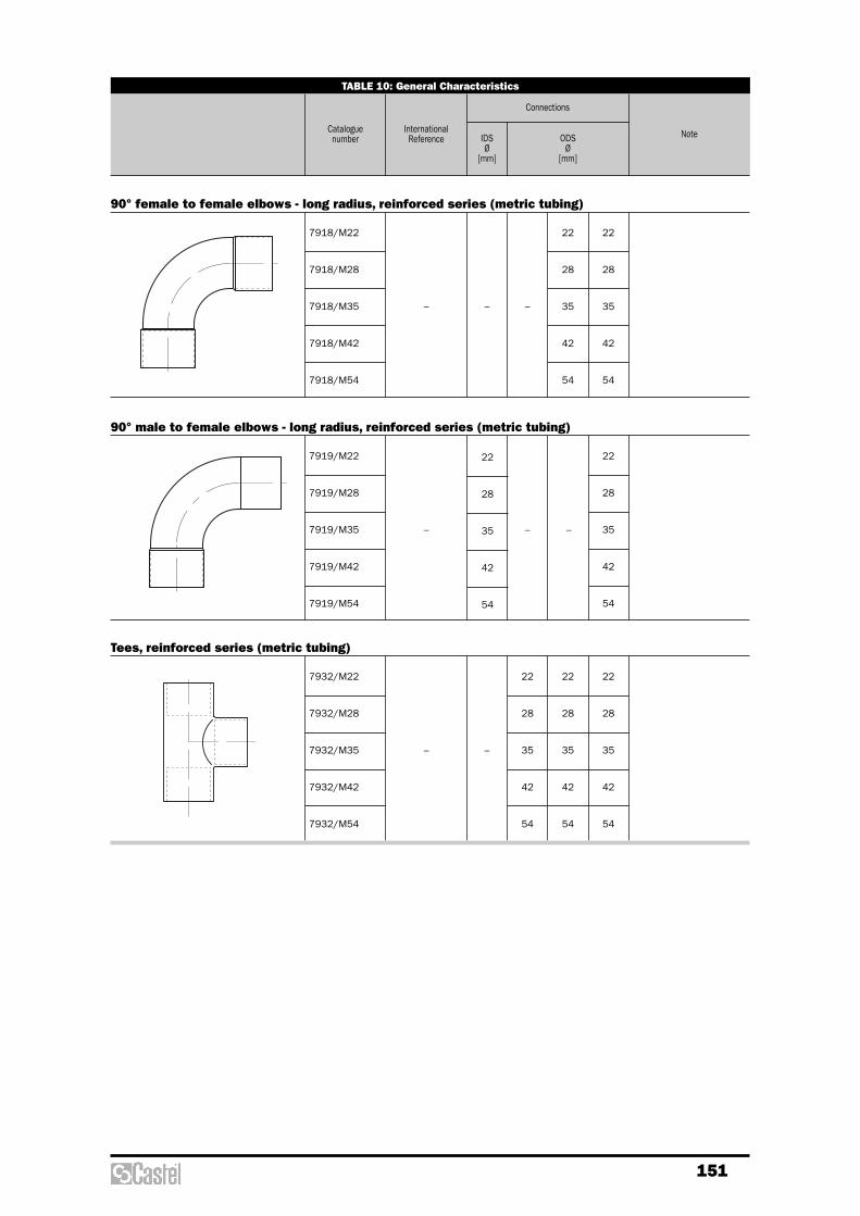
151
TABLE 10: General Characteristics
InternationalReference
Cataloguenumber IDS
Ø[mm]
ODSØ
[mm]
Note
Connections
7918/M22
7918/M28
7918/M35
7918/M42
7918/M54
– – –
22
28
35
42
54
22
28
35
42
54
90° female to female elbows - long radius, reinforced series (metric tubing)
7919/M22
7919/M28
7919/M35
7919/M42
7919/M54
– ––
22
28
35
42
54
22
28
35
42
54
90° male to female elbows - long radius, reinforced series (metric tubing)
7932/M22
7932/M28
7932/M35
7932/M42
7932/M54
– –
22
28
35
42
54
22
28
35
42
54
22
28
35
42
54
Tees, reinforced series (metric tubing)


Access fittings &valve cores
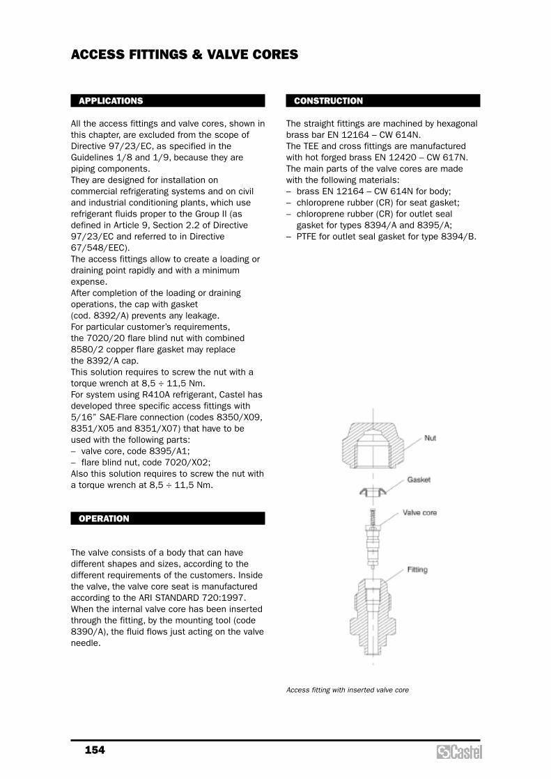
154
CONSTRUCTION
The straight fittings are machined by hexagonalbrass bar EN 12164 – CW 614N.The TEE and cross fittings are manufacturedwith hot forged brass EN 12420 – CW 617N.The main parts of the valve cores are madewith the following materials:– brass EN 12164 – CW 614N for body;– chloroprene rubber (CR) for seat gasket;– chloroprene rubber (CR) for outlet seal
gasket for types 8394/A and 8395/A;– PTFE for outlet seal gasket for type 8394/B.
APPLICATIONS
All the access fittings and valve cores, shown inthis chapter, are excluded from the scope ofDirective 97/23/EC, as specified in theGuidelines 1/8 and 1/9, because they arepiping components.They are designed for installation oncommercial refrigerating systems and on civiland industrial conditioning plants, which userefrigerant fluids proper to the Group II (asdefined in Article 9, Section 2.2 of Directive97/23/EC and referred to in Directive67/548/EEC).The access fittings allow to create a loading ordraining point rapidly and with a minimumexpense.After completion of the loading or drainingoperations, the cap with gasket (cod. 8392/A) prevents any leakage.For particular customer’s requirements,the 7020/20 flare blind nut with combined8580/2 copper flare gasket may replace the 8392/A cap.This solution requires to screw the nut with atorque wrench at 8,5 ÷ 11,5 Nm.For system using R410A refrigerant, Castel hasdeveloped three specific access fittings with5/16” SAE-Flare connection (codes 8350/X09,8351/X05 and 8351/X07) that have to beused with the following parts:– valve core, code 8395/A1;– flare blind nut, code 7020/X02;Also this solution requires to screw the nut witha torque wrench at 8,5 ÷ 11,5 Nm.
OPERATION
The valve consists of a body that can havedifferent shapes and sizes, according to thedifferent requirements of the customers. Insidethe valve, the valve core seat is manufacturedaccording to the ARI STANDARD 720:1997.When the internal valve core has been insertedthrough the fitting, by the mounting tool (code8390/A), the fluid flows just acting on the valveneedle.
ACCESS FITTINGS & VALVE CORES
Access fitting with inserted valve core

155
TABLE 1: General Characteristics
Cataloguenumber SAE Flare ODS IDS
m fNPT
Ø[in.]
Ø[in.]
Ø[mm]
Ø[mm]
PS [bar]
L Ch D H
Connections Dimensions [mm]
8350/22 1/4" –
–
–
–
–
–
–
–
–
–
–
–
1/4" – – – 26 11 – –
Straight access fittings
8350/X01 1/4" – 6 3/8" – 20 11 – –
1/4" – – – 6 90 11 – –
8350/X09 5/16" 1/4" – – – 27 14 9,4 2,1
8351/2
8351/X04
8351/X05
8351/X07
1/4"
5/16"
–
6
–
–
–
3/8"
8-10
6
7
6
30
26
27
11
14
– –
8351/X02 1/4" – 5
1/4"
–
3/8"
8 26 11 – –
8352/22 1/4" – – – – – – 31 11 – –
1/4" –
1/8"
1/4"
3/8"
– – – –
28
33
38
11
14
17
– –
1/4" 1/4" – – – – – 35 17 – –
8354/21
8354/22
8354/23
8362/22
8350/X03
45

156
TABLE 2: General Characteristics
Catalogue number SAE Flare IDS
m fNPT
Ø[in.]
Ø[mm]
PS [bar]
L Ch D H
Connections Dimensions [mm]
Note
1/4" – – – 6
45
43 – – 24
The valve core may beinstalled on each of thetwo 1/4” SAE Flareconnections.
8380/122 1/4" – 1/8" – – 45 – – 24
TEE access fittings
8380/X01
1/4" 1/4" – – – 45
50
49
– – 24
With valve-core openingdevice on femaleconnection.The valve core may beinstalled on each of thetwo 1/4” SAE Flareconnections
The valve core may beinstalled on each of thetwo 1/4” SAE Flareconnections
TEE access fittings with swivel nuts
8380/X06
8380/X08
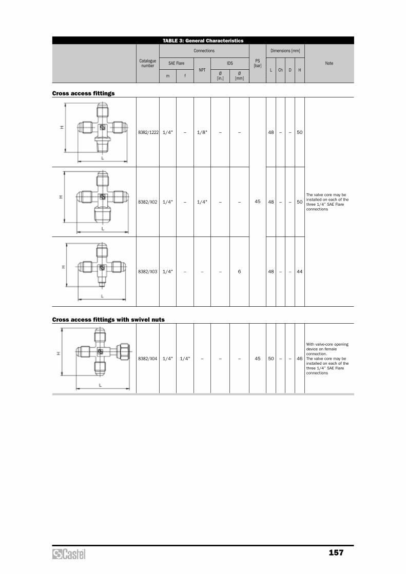
157
TABLE 3: General Characteristics
Cataloguenumber SAE Flare IDS
m fNPT
Ø[in.]
Ø[mm]
PS [bar]
L Ch D H
Connections Dimensions [mm]
Note
1/4" – 1/8" – –
45
48 – – 50
The valve core may beinstalled on each of thethree 1/4” SAE Flareconnections
1/4" – 1/4" – – 48 – – 50
Cross access fittings
1/4" – – – 6 48 – – 44
8382/1222
1/4" 1/4" – – – 45 50 – – 46
With valve-core openingdevice on femaleconnection.The valve core may beinstalled on each of thethree 1/4” SAE Flareconnections
Cross access fittings with swivel nuts
8382/X04
8382/X02
8382/X03
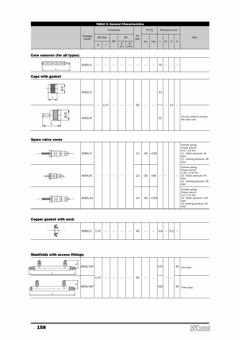
158
TABLE 4: General Characteristics
Cataloguenumber SAE Flare IDS
m fNPT
Ø[in.]
Ø[mm]
PS [bar]
Lmaxmin Ch D H
Connections Dimensions [mm]TS [°C]
Note
– – – – – – – – 75 – – –8390/A
– 1/4” – – – 35 – –
13
– 13 –
Caps with gasket
8392/A
22 The key needs to removethe valve core.8392/B
Core remover (for all types)
1/4" – – – – –45 2,8 – 5,2 –8580/2
Copper gasket with neck
1/4" – – – – –45
175
– –
30 Four ways
162 30 Three ways9900/X87
Manifolds with access fittings
9900/X47
–
–
– – – – –
(1) -40 +100
(2) -30 +90
(4) -40 +100
– – – –
Outside spring.Torque wrench0,4 / 0,8 Nm.(1) - Static pressure: 40[bar](1) - working pressure: 28[bar]
Outside spring.Torque wrench0,4 / 0,5 Nm.(4) - Static pressure: 140[bar](4) -working pressure: 60[bar]
8394/A
Outside spring.Torque wrench0,30 / 0,35 Nm.(2) - Static pressure: 40[bar](2) - working pressure: 28[bar]
8394/B
8395/A1
Spare valve cores

Accessories and spare parts

160
KIT N° ITEM CODE DESCRIPTION SUITABLE FOR PRODUCTS NOTE
ACCESSORIES AND SPARE PARTS FOR SOLENOID VALVES
G9150/R06
9150/R07
9150/R08
9150/R09
9150/R10
9151/R04
9150/R50
9150/R11
9150/R43
008217
008218
008229
004238
200193
009060
008323
200292
004254
008323
200292
200646
004259
008323
200292
009003
004257
004298
008323
004571
200431
004266
004299
008323
004571
009894
004251
004625
008323
004571
009278
009277
004251
004625
008323
200292
004118
004253
004256
004254
004692
008387
008415
008393
004251
008966
004256
004692
Yellow nut for fixing coil
Black screw for fixing coil
O Ring for yellow nut
O Ring under coil
Bracket
Screw
Plunger
Plunger spring
Nut/body O Ring
Plunger
Plunger spring
Diaphragm
Nut/body O Ring
Plunger
Plunger spring
Diaphragm
Cover/body O Ring
Cover/body screws
Plunger
Plunger spring
Diaphragm
Cover/body O Ring
Cover/body screws
Plunger
Plunger spring
Diaphragm
Cover/body O Ring
Cover/body screws
Plunger
Plunger spring
Piston
Piston ring
Cover/body O Ring
Cover/body screws
Plunger
Plunger spring
Diaphragm
Cover/body O Ring
Pilot O Ring
Nut/cover O Ring
Cover/body screws
Piston
Piston ring
Piston spring
Cover/body O Ring
New Pilot O Ring
Old Pilot O Ring
Cover/body screws
All the solenoid valves
All the solenoid valves
All the solenoid valves
All the solenoid valves
N.C. and N.O. solenoid valves type:
1020/..; 1028/..;
1064/..; 1068/..;
1070/4 - /5; 1078/4 - /5 - /M12; 1079/7;
1164/..; 1168/..;
1170/4 - /5; 1178/4 - /5 - /M12; 1512/..;
1522/..; 1132/03 - /04
N.C. solenoid valves type:
1020/..; 1028/..
N.C. solenoid valves type:
1064/..; 1068/..
1098/9; 1099/11
1078/11; 1079/13 - /M42
N.C. solenoid valves type:
1070/4 - /5; 1078/4 - /5 - /M12;
1079/7
N.C. solenoid valves type:
1070/6; 1078/6 - /7; 1079/9
N.C. solenoid valves type:
1090/5 - /6; 1098/5 - /6 - /7; 1099/9
N.C. solenoid valves type:
1050/5 - /6; 1058/5 - /6 - /7; 1059/9
N.C. solenoid valves type:
1078/9; 1079/11
N.C. and N.O. solenoid valves type:
1098/9; 1099/11
1198/9
Diaphragm pilot operated spare
parts for:
1098/9; 1099/11; 1078/11;
1079/13 - /M42
Valves out of stock
Main piston pilot operated
spare parts

161
KIT N° ITEM CODE DESCRIPTION SUITABLE FOR PRODUCTS NOTE
ACCESSORIES AND SPARE PARTS FOR SOLENOID VALVES
9150/R39
9150/R35
9150/R34
9151/R05
9150/R51
9150/R42
9150/R15
9150/R12
9150/R13
9150/R14
008387
008415
008393
004691
008966
004256
004692
N.D.
200646
004259
004238
008757
009003
004257
004254
004238
004298
200286
008757
009894
004251
004254
004238
004625
200286
008757
009278
009277
004251
004254
004238
004625
200286
008757
004118
004253
004256
004254
004238
004692
200286
200581
200292
004242
200581
200292
200520
004244
004298
200581
200292
004617
004625
200581
200292
200552
004246
004242
004309
Piston
Piston ring
Piston spring
Cover/body O Ring
New pilot O Ring
Old pilot O Ring
Cover/body screws
Pre-assembled armature with nuts
Diaphragm
Nut/body O Ring
O Ring under coil
N.O. armature group
Diaphragm
Cover/body O Ring
Nut/body O Ring
O Ring under coil
Cover/body screws
Nut
N.O. armature group
Diaphragm
Cover/body O Ring
Nut/cover O Ring
O Ring under coil
Cover/body screws
Nut
N.O. armature group
Piston
Piston ring
Cover/body O Ring
Nut/cover O Ring
O Ring under coil
Cover/body screws
Nut
N.O. armature group.
Diaphragm
Cover/body O Ring
Pilot O Ring
Nut/cover O Ring
O Ring under coil
Cover/body screws
Nut
Punger
Plunger spring
Nut/body O Ring
Plunger
Plunger spring
Diaphragm
Cover/body O Ring
Cover/body screws
Plunger
Plunger spring
Diaphragm
Cover/body screws
Plunger
Plunger spring
Diaphragm
No 2 pilot O Ring
Nut/cover O Ring
Cover/body screws
N.C. and N.O. solenoid valves type:
1078/11; 1079/13 - /M42
1178/11
N.O. solenoid valves type:
1164/..; 1168/..
1198/9
1178/11
N.O. solenoid valves type:
1170/4- /5; 1178/4 - /5 - /M12
N.O. solenoid valves type:
1190/5 - /6; 1198/5 - /6 - /7
N.O. solenoid valves type:
1150/5 - /6; 1158/5 - /6 - /7
N.O. solenoid valves type:
1178/9
Solenoid valves for different fluids type:
1512/..
Solenoid valves for different fluids type:
1132/03 - /04
Solenoid valves for different fluids type:
1132/06 - /08
Solenoid valves for different fluids type:
1142/010 - /012
Main piston pilot operated
spare parts
Diaphragm pilot operated spare
parts for:
1198/9
1178/11

162
KIT N° ITEM CODE DESCRIPTION SUITABLE FOR PRODUCTS NOTE
ACCESSORIES AND SPARE PARTS FOR CHECK VALVES
9150/R16
9150/R17
9150/R18
9150/R19
9150/R52
9150/R53
9150/R54
9150/R55
003558
001869
004251
004299
003559
000728
004691
004692
003854
000728
008002
004302
003855
001857
004261
004302
003558
001869
008863
004299
003559
000728
009174
004692
003854
000728
009175
004302
003855
001857
009176
004302
Piston
Spring
Cover/body O Ring
Cover/body screws
Piston
Spring
Cover/body O Ring
Cover/body screws
Piston
Spring
Cover/body O Ring
Cover/body screws
Piston
Spring
Cover/body O Ring
Cover/body screws
Piston
Spring
Cover/body gasket
Cover/body screws
Piston
Spring
Cover/body gasket
Cover/body screws
Piston
Spring
Cover/body gasket
Cover/body screws
Piston
Spring
Cover/body gasket
Cover/body screws
Check valves type:
3120/7 - /9 - /M22 - /M28
3140/7 - /9 - /M28
3180/7 - /9 - /M28
Check valves type:
3120/11
3140/11
3180/11
Check valves type:
3120/13 - /M42
3140/13 - /M42
Check valves type:
3120/17
3140/17 - /21 - /25
3160/17; 3180/13 - /M42 - /17
Check valves type:
3122/7 - /9 - /M22 - /M28
3142/7 - /9 - /M28
3182/7 - /9 - /M28
Check valves type:
3122/11
3142/11
3182/11
Check valves type:
3122/13 - /M42
3142/13 - /M42
Check valves type:
3122/17
3142/17 - /21 - /25
3182/13 - /M42 - /17
Valves out of stock
Valves out of stock
Valves out of stock
Valves out of stock

163
KIT N° ITEM CODE DESCRIPTION SUITABLE FOR PRODUCTS NOTE
ACCESSORIES AND SPARE PARTS FOR INDICATORS
9150/R20
9150/R21
003575
007779
004259
004270
007780
004259
Nut
Protection cap
Nut/body O Ring
Pre-assembled nut
Protection cap
Nut/body O Ring
Liquid indicators type:
3610/..; 3620/..; 3640/..; 3650/..
Moisture - liquid indicators type:
3710/..; 3720/..; 3740/..; 3750/..;
3770/..; 3771/..; 3780/..; 3781/..
3610/; 3640/..; 3650/..
out of stock
3710/..; 3740/..; 3750/..;
out of stock
ACCESSORIES AND SPARE PARTS FOR FILTERS
G9150/R05
9150/R57
9150/R58
8354/22
8392/A
8394/B
003319
003322
009406
003324
007677
005535
004592
008336
008304
008305
008307
008403
008345
008344
008303
008306
Access fitting
Cap with gasket
valve core
Spring
Flange gasket
Dehydrating block cover
Dehydrating block bottom
Filtering tube for one block
Mechanical block cover
Mechanical block bottom
Flange gasket
Dehydrating block cover
Dehydrating block bottom
Screw for filtering tube
Filtering tube
Filtering tube
Filtering tube
Mechanical block cover
Mechanical block bottom
Filters with replaceable block type:
4411/..; 4412/..; 4413/..; 4414/..
4421/..; 4423/..; 4424/..
All the filters series 44
Filters with replaceable block type:
4411/..; 4412/..; 4413/..; 4414/..
Filters with replaceable block type:
4411/..A-B; 4412/..A-B; 4413/..A-B;
4414/..A-B
Filters with replaceable block type:
4411/..C
Filters with replaceable block type:
4421/..; 4423/..; 4424/..
Filters with replaceable block type:
4421/..A; 4423/..A; 4424/..A
Filters with replac. block type: 4421/..A
Filters with replac. block type: 4423/..A
Filters with replac. block type: 4424/..A
Filters with replaceable block type:
tipo:4421/..C

164
CHANGEOVER VALVES
9150/R24
9150/R25
004297
004329
004330
004348
000529
000534
000535
001039
3039/44
004260
009036
008281
Gland
Gland seal gaskets
Gland seal gaskets
Washer
Gland
Gland seal gaskets
Gland seal gaskets
Washer
Pair of connetions 1/2"NPT female
Connection/body O Ring
Cap
Cap
Changeover devices 3032/44
- /64 - /66
Changeover valve 3032/108
Changeover valve 3032/44
Changeover valve 3032/64 - /66
HERMETIC VALVES
9150/R23
G9150/R33
003664
000384
000957
000382
007486
000913
004307
004326
Gland
Gland seal gaskets
Gland seal gaskets
Washer
Cap
Spindle
Screw
Spring washer
All the hermetic valves type:
6010/..; 6012/..; 6020/..; 6060/..;
6070/..
Hermetic valves type:
6010/2; 6012/22
Hermetic valves type: 6020/..
6060/..; 6070/..
out of stock
RECEIVER VALVES
9150/R23
9150/R24
9150/R25
003664
000384
000957
000382
007486
000913
001641
004297
004329
004330
004348
009036
001647
000529
000534
000535
001039
008282
001038
Gland
Gland seal gaskets
Gland seal gaskets
Washer
Cap
Spindle
Spindle
Gland
Gland seal gaskets
Gland seal gaskets
Washer
Cap
Spindle
Gland
Gland seal gaskets
Gland seal gaskets
Washer
Cap
Spindle
Receiver valves type:
6110/21 - /22 - /23 - /32 - /33
6120/22 - /23 - /33
6132/..
6140/22 - /23
Receiver valves type:
6110/21 - /22; 6120/22; 6140/22 -
Receiver valves type:
6110/23 - /32 - /33; 6120/23 - /33
Receiver valves type:
6110/43 - /44 - /54
6120/43 - /44 - /54
Receiver valves type:
6110/66
6120/66
BALL SHUT-OFF VALVES
009035
009256
Cap
Cap
Ball shut-off valves 3033/..
Ball shut-off valves 3063/44
KIT N° ITEM CODE DESCRIPTION SUITABLE FOR PRODUCTS NOTE

165
STOP VALVES
9150/R26 000822
000823
000824
007476
Gland
Gland seal gasket
Gland seal gasket
Washer
Stop valves type:
6170/66 - /77
ROTALOCK VALVES
9150/R23 003664
000384
000957
000382
7910/6
7990/6
7910/8
7990/8
Gland
Gland seal gasket
Gland seal gasket
Washer
Steel solder connection
3/4" UNF-16
PTFE gasket for 7910/6
Steel solder connection
1" UNS-16
PTFE gasket for 7910/8
Rotalock valves type:
6310/..
6320/..
To be ordered separately
CAPPED VALVES
9150/R23 003664
000384
000957
000382
007486
002337
005174
007619
007676
Gland
Gland seal gasket
Gland seal gasket
Washer
Cap
Spindle
Nipple/body O Ring
Spindle
Nipple/body O Ring
Capped valves type:
6410/..; 6420/..; 6460/..
Capped valves type:
6410/2 - /3 - /4 - /5
6420/2 - /3 - /M10 - /M12 - /4 - /5
6460/22A.
Capped valves type:
6410/6
6420/M18 - /6 - /M22 - /7
KIT N° ITEM CODE DESCRIPTION SUITABLE FOR PRODUCTS NOTE

166
GLOBE VALVES
9150/R24
9150/R27
9150/R28
9150/R26
9150/R29
9150/R30
004297
004329
004330
004348
001635
004296
007637
004299
004251
008863
007638
004692
004691
009174
000822
000823
000824
007476
001228
000830
004302
007639
008002
009175
007640
004261
009176
Gland
Gland seal gaskets
Gland seal gaskets
Washer
Cap
Cap gasket
Spindle/plate group
Cover/body screws
Cover/body O Ring
Cover/body gasket
Spindle/plate group
Cover/body screws
Cover/body O Ring
Cover/body gasket
Gland
Gland seal gaskets
Gland seal gaskets
Washer
Cap
Cap gasket
Cover/body screws
Spindle/plate group
Cover/body O Ring
Cover/body gasket
Spindle/plate group
Cover/body O Ring
Cover/body gasket
Globe valves type:
(1) 6510/M22 - /7 - /M28 - /9 - /11
6512/M22 - /7 - /M28 - /9 - /11
(1) 6520/7 - /9 - /11
(1) 6530/M22 - /7 - /M28 - /9 - /11
6532/M22 - /7 - /M28 - /9 - /11
Globe valves type:
(1) 6510/M22 - /7 - /M28 - /9
6512/M22 - /7 - /M28 - /9
(1) 6520/7 - /9
(1) 6530/M22 - /7 - /M28 - /9
6532/M22 - /7 - /M28 - /9
Globe valves type:
(1) 6510/M22 - /7 - /M28 - /9
(1) 6520/7 - /9
(1) 6530/M22 - /7 - /M28 - /9
Globe valves type:
6512/M22 - /7 - /M28 - /9
6532/M22 - /7 - /M28 - /9
Globe valves type:
(1) 6510/11; 6512/11
(1) 6520/11; (1) 6530/11;
6532/11
Globe valves type:
(1) 6510/11; (1) 6520/11;
(1) 6530/11
Globe valves type:
6512/11; 6532/11
Globe valves type:
(1) 6510/13 - /M42 - /17
6512/13 - /M42 - /17
(1) 6520/13 - /M42 - /17
(1) 6530/13 - /M42 - /17
6532/13 - /M42 - /17
Globe valves type:
(1) 6510/13 - /M42
6512/13 - /M42
(1) 6520/13 - /M42
Globe valves type:
(1) 6510/13 - /M42
(1) 6520/13 - /M42
Globe valves type:
6512/13 - /M42
Globe valves type:
(1) 6510/17; 6512/17
(1) 6520/17; (1) 6530/13 - /M42 - /17
6532/13 - /M42 - /17
Globe valves type:
(1) 6510/17; (1) 6520/17
(1) 6530/13 - /M42 - /17
Globe valves type:
6512/17
6532/13 - /M42 - /17
(1) Valves out of stock
KIT N° ITEM CODE DESCRIPTION SUITABLE FOR PRODUCTS NOTE

167
BALL VALVES
9150/R46
009055
009750
003752
009036
009751
004296
009037
009752
000530
009038
009753
009754
009207
009208
8394/A
8392/A
Plastic cap
Brass cap
Brass cap gasket
Plastic cap
Brass cap
Brass cap gasket
Plastic cap
Brass cap
Brass cap gasket
Plastic cap
Brass cap
Brass cap gasket
Brass cap
Brass cap gasket
Valve core
Cap with gasket
Ball valves type:
6590/M6 - /2 - /3 - /3A - /M10 -
/M10A - /M12 - /M12A - /4 - /4A
6591/5
6590/M15 - M15A - /5 - /5A - /M18
- /M18A - /6 - /6A
6591/7
Ball valves type:
6590/7 - /7A
6591/M28 - /9
6590/M28 - /M28A - /9 - /9A
6591/11
Ball valves type:
6590/11 - /11A
6591/13 - /M42
6590/13 - /13A - /M42 - /M42A
6591/17
Ball valves type:
6590/17 - /17A
6591/21 - /21A
6591/M64 - /M64A
Ball valves type:
6590/M64A - /21A
6591/24A - /25A
6590/25A
6591/28A - /29A - /33A - /34A
Ball valves with access fitting
COMPRESSOR VALVES
9150/R23 003664
000384
000957
000382
Gland
Gland seal gasket
Gland seal gasket
Washer
Compressor valves type:
6640
Valves out of stock
GAUGE MOUNTING VALVES
9150/R23 003664
000384
000957
000382
Gland
Gland seal gasket
Gland seal gasket
Washer
Gauge mounting valves:
8320/21 - /22
KIT N° ITEM CODE DESCRIPTION SUITABLE FOR PRODUCTS NOTE
168
NOTE
