apps.dtic.mil · individual protection and relocation attributes, and each may represent local...
TRANSCRIPT


I
I Report No. 4845 Bolt Beranek and Newman Inc.
ITable of Contents
I1. Introduction ...... . . . . . . . . . . . . . . . .
1.1 Notation......................................... 12. Memory Architecture ........... . ............. 32.1 Address Spaces .................................... 32.2 Address Transformation ............................ 92.3 Segments F8through FF........................... 162.4 Design Considerations........ ... ....... . ........ 193. Subspace Zero .............................. ....... 223.1 EPROM ............................................ 233.2 Subspace Zero Main-Memory..... . ... 069..69940 253.3 Segment Attributes Registers...................... 253.4 Address Space Attribute Registeroo....... 000..600.. 273.5 Real-Time Clock/Timer... ..................... 283.6 Block Transfer..........., ....... ...... . 000 303.7 Post Event......................313.8 Dual Queue Functions............... . ... ... . 343.9 Various Kernel Functions.. ........... ... 000..0 393.9.1 Enqueue, dequeue, push. remove......qq.......... 403.9.2 Clear-Then-XOR and Clear-Then-Add ............... 413.10 Miso register .... , . .. ....... 0 ...... ....... . 42
3.11 Interprocessor Interrupts and Resets ............. 433.12 Interrupt Control Register....................... 433.13 Microcode Version Number.. ....................... 463.14 Memory Control Registers. ........................ 473.15 PNC status register ...... .. .... ....... ... ..... . 483.16 Verify User Write-Access ....................... 493.17 Conclusion ........... 000........................ 50
I - i

Report No. 4845 Bolt Beranek and Newman Inc.
FIGURES
Physical Address Format................................... 4Virtual Address Format...... ............. ........... 7Processor Node Diagram................... .......... 8Virtual to Physical Address Translation.................. 12Control Registers....................... .*...** ...... 24SAR and ASAR Layout ...................................... 26
- ii -
mr ...... . .y . -- :. . . . ., . .
Report No. 4845 Bolt Beranek and Newman Inc.
1. Introduction
This Quarterly Technical Report, Number 12, describes
aspects of our work performed under Contract No. MDA903-78-C-0356
during the period from 1 May 1981 to 31 July 1981. This is the
twelfth in a series of Quarterly Technical Reports on the design
of a packet speech concentrator. the Voice Funnel.
The hardware design of the Processor Node has been described
previously in Quarterly Technical Reports Numbers 4 and 6. They
describe the memory architecture of the machine and the role
played by the Processor Node Controller (PNC). The PNC is a
microcoded bit-slice processor which implements many special
functions for the Processor Node. This report defines the
functions of the PNC and updates the description of the memory
architecture. It supersedes the description of the memory system
described in Quarterly Technical Report Number 4.
1.1 Notation
Throughout this document, several notational conventions are
used to represent the allowed access modes of a resource and the
symbol names used to access these resources.
The protection mechanism checks all accesses according to
* whether the Processor Node is in Kernel or User mode and whether
V the access is a read, write, or instruction fetch. We have
I

Report No. 4845 Bolt Beranek and Newman Inc.
adopted a convention which is used by several operating systems
to reflect these types of access. The string "RWXrwx" has six
characters. Each one represents one mode of access. "R" means
that it can be read in kernel mode. "W" means that it can be
written in kernel mode. "X" means that it can be fetched as an
instruction in kernel mode. The lower case characters have the
same meanings but for user mode instead of kernel mode. If the
character is present, then that access mode is legal. If
instead, the character is replaced with an underline, then that
access mode is illegal. For example. "RW.rr" means that kernel
read or write accesses or user mode read accesses are legal, but
that user mode writes are illegal as are any instruction fetches.
The second notational consideration is with regard to the
names of symbols that are used to refer to special control
registers or memory locations. Throughout the document, these
symbols are represented in a bold typeface such as AsAr.
Finally, throughout this report, hexadecimal notation is
used for addresses of the various variables and bit values in the
machine.
-2-

Report No. 4845 Bolt Beranek and Newman Inc.
2. Memory Architecture
The computing power of a machine depends as much on the
architecture of its memory system as it does on the architecture
of its processor.
Three considerations dominate the design of the memory
system of the Butterfly Multiprocessor: 1) the software of this
machine is based on "processes" (rather than the strips of the
Pluribus); 2) it will support large and complex software,
requiring protection and separation between the component pieces;
and 3) it is a tightly-coupled multiprocessor, so that shared
memory will be an important form of communications.
The virtual memory system of the Butterfly Multiprocessor
provides each process with up to 256 memory segments. Each
segment can be from 256 to 64K bytes long. Each segment has
individual protection and relocation attributes, and each may
represent local memory (i.e. memory on the same node as the
processor), remote memory, or I/O device registers.
2.1 Address Spaces
The Butterfly Multiprocessor has a 32-bit physical address
space. This address space is the concatenation of the physical
address spaces of all the Processor Nodes in the machine. The
physical address space of each Processor Node consists in turn of
!-3

Report No. 4845 Bolt Beranek and Newman Inc.
4 "subspaces". Each subspace is now IM bytes long. The 32-bit
physical address is organized as an 8-bit Processor Node number
(permitting up to 256 Processor Nodes), a 2-bit subspace number,
2 spare bits, and a 20-bit subspace offset. This address format
is illustrated in Figure 1.
(8) 1(2)1(2)] (20)
PROCESSOR SUBSPACENODE OFFSET
NUMBER U SED
SUBSPACENUMBER
Figure 1 . Physical Address Format {
The 4 subspaces of a Processor Node are:
- Subspace 0 contains the EPROM. a portion of mainmemory, and many special Processor Node controlregisters. It is described in Section 3 of thisreport.
- Subspace 1 contains the control registers on the I/0boards. It is subdivided into four equal parts, onefor each possible I/0 board.
- Subspace 2 contains the memory which is local to thisProcessor Node and which should be addressed directly.
- Subspace 3 indicates that the access should be made viathe switch. Local memory may also be accessed throughSubspace 3 but can be more efficiently accessed throughSubspace 2. This distinction is addressed in moredetail below.
-4

Report No. 4845 Bolt Beranek and Newman Inc.
One of the more important spaces is Subspace 2, where the
physical memory for this Processor Node is located. As with all
subspaces, it is limited in length to 1M bytes. This bounds the
amount of memory that may be placed on a Processor Node. In
addition, only 4 memory boards can be attached to a Processor
Node. Since only 16K-bit memory IC's are presently available,
the maximum amount of memory on one memory board is 128K bytes
and as a result, the maximum amount of memory on a Processor Node
is 512K bytes. The maximum amount of memory in a Butterfly
Multiprocessor with 256 Processor Nodes is thus 128 bytes. In
the future. we expect to use the two unused bits in the Segment
Attribute Register and Physical Address to expand the amount of
physical memory on a node to 4M bytes. With 64K memory chips and
a new memory board layout, this should be achievable.
The 32-bit physical address uniquely represents each
addressable memory and control register in the machine. Its
Processor Node, subspace, and subspace offset are fully
specified. As we will see later, the hardware uses Subspace 3 in
a special way which places limits on how a physical address is
interpreted. Subspace 3 is not a subspace in the usual sense.
Rather, it is a way of indicating to the hardware that this
reference is not to be interpreted as a local reference.
While the physical address space reflects the structure and
A. needs of the hardware, the virtual address space reflects the
structure and needs of the software. The software of the
-5-

Report No. 4845 Bolt Beranek and Newman Inc.
Butterfly Multiprocessor is divided into processes. Each process
executes in its own virtual address space, although the virtual
address spaces of several processes may reference the same
physical memory, if desired. Thus, while there can only be one
physical address space in a machine, there may be many virtual
address spaces in each Processor Node.
The size of the virtual address space is constrained by the
processor being used. The MC68000 is, in a large sense, a 32-bit
machine. As such. address registers within the machine have a
capability for 32-bit operations. However, only the lower 24
bits of the address are actually supported in the current
implementation of the MC68000. As a result, for our purposes, a
virtual address is a 24-bit number.
In the Butterfly Multiprocessor we treat the 24-bit virtual
address as an 8-bit segment number followed by a 16-bit offset
within the segment, as shown in Figure 2.
(8) (8) (16)
UNUSED SEGMENT SEGMENT.NUMBER OFFSET
4-4
Figure 2 . Virtual Address Format
-6-

Report No. 4845 Bolt Beranek and Newman Inc.
This divides the virtual address space into 256 segments. Each
segment can be from 256 to 64K bytes long. Each segment has
independent protection and relocation attributes and may
represent local memory (on the same Processor Node), remote
memory, local I/O device registers, or local control registers.
The structure of the Processor Node is shown in Figure 3.
This figure illustrates the distinction between the virtual and
the physical address spaces. The processor (and as a result, the
programmer) operates in a virtual address space. Every memory
reference undergoes a translation into a physical address by the
Memory Management Unit (MMU) before the access is performed. The
Processor Node Controller, the switch, the I/O devices, and the
memory live in a physical address space. The MMU links these two
spaces.
The goal of a virtual memory system is to allow the software
to be better protected and more easily written. The virtual and
physical address spaces have different constraints. The physical
address space must be large enough that the ultimate main memory,
I/O, and special register spaces can be represented. This space
must be organized so that any physical address can be reached
quickly.
The virtual address space, on the other hand, must be large
enough that the program may be written without becoming
"cramped". There is no reason to suppose that the physical and
-7-"

Report No. 4845 Bolt Beranek and Newman Inc.
PROCESSOR
MC 68000
VIRTUAL
ADDRESSOE MEMORY SPACECNTOER MANAGEMENT
UNIT PHYSICALADDRESS
SPACE
MEMORY INTERFACE]
l BARS BOARDS
II I
I
Processor Node DiagramFigure 3
- 8-

Report No. 4845 Bolt Beranek and Newman Inc.
virtual spaces should be the same size or should be organized in
the same way.
Having decided to implement a virtual memory system. we face
the options of segmentation and paging. Segmentation is the
division of an address space into variable length blocks, usually
by means of a virtual memory mapping. Paging, on the other hand,
divides the space into fixed length pieces. The implications of
the two schemes are quite different. Segments are intended as an
aid to the sophisticated programmer in organizing the protection,
sharing, and location of his process. Pages are used to break up
the full address space into more manageable fixed size pieces for
the operating system. Often demand paging is used to "cache" the
contents of a virtual address space through swapping on a
secondary storage medium.
Segmentation can be implemented on top of paging, as in the
Multics system. However. such a scheme is too complex and
requires too much additional mechanism to be used here. In
addition, since the MC68000 cannot now support demand paging, we
have determined that a simple segmentation scheme is most
appropriate for the Butterfly Multiprocessor.
2.2 Address Transformation
Memory management separates the virtual address space as
seen by the processing elements from the physical address space.
-9-

Report No. 4845 Bolt Beranek and Newman Inc.
The memory manager serves as an interface between these two
spaces, translating virtual addresses into physical addresses.
The time of the mapping is also a convenient one to perform some
ancillary functions such as protection.
The memory management system of the Butterfly Multiprocessor
contains 512 Segment Attribute Registers (SARs) on each Processor
Node. Each SAR defines the address translation and protection
characteristics for one segment. A set of registers are grouped
together to form an address space for a process. There is also a
single Address Space Attribute Register (ASAR) which, when loaded
with the address and extent of a group of SARs, defines the
currently active address space. The layout and use of SARs and
the ASAR are described in Sections 3.3 and 3.4.
A virtual address space consists of 8, 16, 32, 64, 128, or
256 segments. Since there are 512 SARs this means that the
hardware can support from 64 to 2 address spaces simultaneously.
In order to change address spaces, it is only necessary to change
the ASAR. This will permit faster process switching.
In addition to these segments, every address space shares a
set of 8 segments numbered F8 through FF. These segments are
intended to hold operating system data structures. This will be
described in Section 2.3.
- 10 -

Report No. 4845 Bolt Beranek and Newman Inc.
The virtual address translation function has several phases:
1. Using the ASAR and the segment number from the virtualaddress, select the correct SAR. If the segment numberis invalid, give a bus error.
2. Using the SAR selected above and the segment offsetfrom the virtual address, generate the physicaladdress. If the segment offset is too large, give abus error.
3. Using the SAR and the access mode of the memoryreference (e.g., read vs write, instruction vs data),give a bus error if the access is illegal.
4. Process the access on the basis of its subspace field.
While this appears to be very simple and clean, the actual
implementation in the hardware imposes several constraints. This
implementation is shown in more detail in Figure 4. The address
transformation function is defined as follows.
Three bits of the ASAR contain a code which specifies how
many segments are in this process's address space. If a
reference is made to a segment whose number exceeds this limit,
an error will be generated. Since not all address space sizes
can be specified by an ASAR code, it may be necessary to specify
a larger than required segment count. The SARs for unused
- segments may be marked as zero length.
The least significant 9 bits of the ASAR are logically
"ORed" with the 8-bit segment number (padded with a zero on the
g ! - 1 1 -

Report No. 4845 Bolt Beranek and Newman Inc.
SEGMENTADDRESS ATTRIBUTE
REGISTERS
000SPACE A
16 SEGMENTS ADDRESS
SPACE 8 SPACE16 SEGMENTS ATTRIBUTE
040 REGISTER
00SPACE C [ I32SEGMENTS STARTING VIRTUAL ADDRESS
0100
SEGMENT
SPACE D SEGMENT PAGE OFFSET
32 SEGMENTS
0140OSPACE E
16 SEGMENTS0160
SPACE F18 SEGMENTS
0200
SPACE G /SEGMENT ATTRIBUTE
REGISTER NO. 245
0245
SPACE H
0016 SEGMENTS
SPACE I
03016 SGMENTS0340
PHYSICAL ADDRESS
SPACE J32 SEGMENTI
0400
SPACE K128 SEGMENTS
Virtual to Physical Address TranslationFigure 4
- 12-

1Report No. 4845 Bolt Beranek and Newman Inc.
left) to form an index into the array of SARs. During this
logical "OR", the bottom three bits of the ASAR are ignored and
presumed to be zero. The logical "OR" function is used instead
of addition be-ouse it is more quickly and easily calculated by
the hardware. However. it constrains the allocation of SARs as
discussed further in Section 2.4.
Once the correct SAR has been selected, it is combined with
the segment offset from the virtual address to form the correct
physical address. As the figure illustrates, the least
significant 8 bits of the physical address come directly from
the least significant 8 bits of the virtual address, while the
most significant 16 bits come from the SAR directly.
The 8 bits in between are the sum of fields from the SAR and
the segment offset.
Since the segment offset in a virtual address is 16 bits
long, the largest segment is 64K bytes. However, segments need
not be this large. A segment length field in the SAR defines the
actual length. Each segment is defined to start at an offset of
zero and to increase to this limit. The table below gives the
segment length code and the corresponding limit on the number of
bytes in the segment. The number is given in both decimal and
hexadecimal for convenience. The largest valid segment offset is
one less than this limit. The difference in size between two
successive limits is approximately half of the smaller limit.
- 3__ _ _ - --- -- - 1---- - -.

Report No. 4845 Bolt Beranek and Newman Inc.
This scheme is obviously a bit coarse since the smallest object
that can be controlled is 256 bytes long and large objects will
rarely have bounds which accurately match their length.
Segment Length Segment Offset LimitCode (Decimal) (Hex)
0 0 01 256 1002 512 2003 768 3004 1024 4005 1536 6006 2048 8007 3072 coo8 4096 10009 6144 1800
10 8192 200011 12288 300012 16384 400013 24576 600014 32768 800015 65536 10000
For each virtual-to-physical address translation, the MMU
also checks that the access is being performed in a legal mode.
This protection is on a segment-by-segment basis. All of the
locations in a segment are protected identically. The protection
mechanism checks the access according to whether the Processor
Node is in Kernel or User mode and whether the access is a data
read or write or an instruction fetch. If an inconsistency is
detected, a bus error will be generated and the access will be
aborted. The code that specifies which modes of access are legal
is in the SAR for the segment. The table below gives the
protection codes and the corresponding set of legal access modes:
- 14 -

IReport No. 4845 Bolt Beranek and Newman Inc.
Protection Allowed AccessCode Characteristics
0 R-r-x1 RXr-x2 RWXrwx3 RWrw_4 R-r_5 RW_6 R7 RW-r_
Once the correct physical address has been generated and its
validity checked, it is necessary to reference the correct
physical memory location. While the physical address can
uniquely specify the physical location, the hardware takes a
short cut.
The hardware interprets the physical address first on the
basis of the subspace field rather than the Processor Node
number. If the subspace is anything but subspace 3 (implying a
remote memory reference), the access proceeds without regard for
the Processor Node number. If the access is to subspace 3. a
switch message is created even if the Processor Node number
refers to the local Processor Node. This is important in
achieving the highest possible memory speed and simplifies the
hardware. Because of constraints in the PNC microcode, the
software must maintain the correct values in the Processor Node
field of all SARs, not only those that reference subspace 3.
Similarly, the software normally detects when a segment refers to
local memory and declares it to be in Subspace 2.
-15-

Report No. 4845 Bolt Beranek and Newman Inc.
As a result of this implementation, only memory may be
accessed across the switch. It is not possible to generate an
access to a remote Processor Node's I/O device registers, its
Processor Node Controller registers, or its EPROM.
It is possible to send messages out through the switch and
back to oneself simple *f -eferencing subspace 3 with the correct
Processor Node nun,. nis will be useful in testing this
Processor Node's sw " interface and a portion of the switch.
2.3 Segments FS tnrough FF
As described so far, the address space of a process consists
of a set of N segments numbered from zero to N-i. However, in
addition, every address space also has access to the segments F8
through FF. They are set up by the operating system and are
reserved for the operating system's use.
A reference to one of these segments is handled by the
hardware exactly as a normal reference, except that the size code
in the ASAR is not checked to see if the segment number is legal.
During the access, the hardware logically OR's the segment number
and the low nine bits of the ASAR to form the index into the
table of SARa. Notice that the numbers F8, F9, FA, FB, FC, FD,
FE, and FF are all ones in bits 7 through 3. Also notice that
the ASAR is always zero in bits 2 through 0. Thus, the only bit
of the ASAR that is important after the OR operation is bit 8.
- 16 -

Report No. 4845 Bolt Beranek and Newman Inc.
For example, a reference to segment F9 will result in the use of
either SAR F9 or SAR 1F9 depending on the ASAR, but none of the
other bits of the ASAR will be important. By convention, the
operating system keeps both sets of SARS equal.
There are several other conventions on the use of segments
0, F8 and FF. The 68000 can specify addresses as either 16-bit
quantities (called short) or 32-bit quantities (called long).
Short addresses are sign extended. Short addresses take up less
memory and instructions that use them are more efficient. This
means that references to segments zero and FF are more efficient
than those to other segments. To take advantage of this, we have
chosen to access the system code and microcode resources via
these two segments. The convention is that segment zero of every
process and SARs FF and 1FF point to subspace zero with RWXrwx
access. For this reason, the addresses given in Section 3 are
short.
Segment F8 is owned and maintained by the Butterfly
operating system, but may be used under certain circumstances by
application programs. In particular, segment F8 maps in physical
memory locations starting at location 0, with RW_r access.
Currently the entire 64K byte segment is mapped in, but this may
change.
The first 80 (hex) locations contain parameters and
variables which are used to communicate with the subspace zero
-17-
Report No. 4845 Bolt Beranek and Newman Inc.
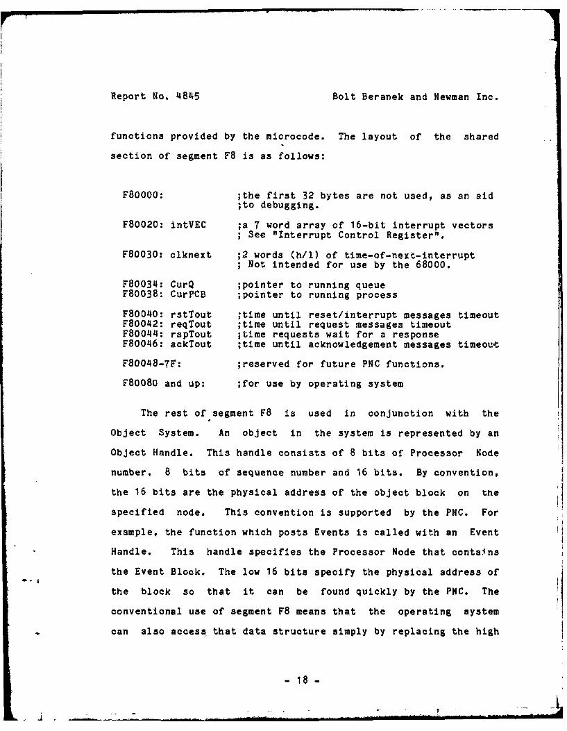
functions provided by the microcode. The layout of the shared
section of segment F8 is as follows:
F80000: ;the first 32 bytes are not used, as an aid;to debugging.
F80020: intVEC ;a 7 word array of 16-bit interrupt vectors; See "Interrupt Control Register".
F80030: clknext ;2 words (h/i) of time-of-next-interruptNot intended for use by the 68000.
F80034: CurQ ;pointer to running queueF80038: CurPCB ;pointer to running process
F80040: rstTout ;time until reset/interrupt messages timeoutF80042: reqTout ;time until request messages timeoutF80044: rspTout ;time requests wait for a responseF80046: ackTout ;time until acknowledgement messages timeou-t
F80048-7F: ;reserved for future PNC functions.
F80080 and up: ;for use by operating system
The rest of segment F8 is used in conjunction with the
Object System. An object in the system is represented by an
Object Handle. This handle consists of 8 bits of Processor Node
number, 8 bits of sequence number and 16 bits. By convention,
the 16 bits are the physical address of the object block on tne
specified node. This convention is supported by the PNC. For
example, the function which posts Events is called with an Event
Handle. This handle specifies the Processor Node that contains
the Event Block. The low 16 bits specify the physical address of
the block so that it can be found quickly by the PNC. The
conventional use of segment F8 means that the operating system
can also access that data structure simply by replacing the high
- 18 -
. ..- - ,..1 ..

Report No. 4845 Bolt Beranek and Newman Inc.
16 bits of the event handle with the constant F8.
Segment F8 is also used in a special way by a class of
special PNC functions which perform indivisible operations for
the 68000. In these cases, addresses in segment F8 are specified
as 32-bit quantities but in fact only the bottom 16 bits are
used. These functions are described in Section 3.9 below.
2.4 Design Considerations
The Memory Management hardware implements a virtual memory
system as described above. The design of any virtual memory
system raises complex issues. This section discusses some of the
decisions which went into this design and elaborates some areas
which require special care in the software which interfaces to
the memory system.
Unfortunately, the ASAR cannot point to any arbitrary map
location because the mapping register which will be used is not
the sum of the ASAR and the segment being addressed, but rather
the "OR" of the two.
In practice, this requires that the rightmost N bits of the
ASAR be zero for a space of 200N segments. The operating system
manages these registers using a "buddy system" allocator which
matches these constraints well.
-19-

Report No. 4845 Bolt Beranek and Newman Inc.
A similar restriction occurs in that the adder in the
translation does not carry past 16 bits in the physical memory
space. This means that there are boundaries in physical memory
every 2*"16 (or 64K) bytes which segments may not cross. This
boundary need not be visible to the application software, and is
easily hidden by the physical memory allocation software: since
the physical memory allocator will not allocate a block of memory
which crosses this boundary, segments which cross it cannot be
constructed.
At any given time a program in the 68000 sees a particular
virtual address space. A virtual address space is limited to a
fixed range of segments. Each segment has certain protection
attributes, and its segment length may also be limited to less
than 64K bytes. Ordinary main memory write requests are
suppressed in hardware if any kind of protection violation
occurs; the 68000 sees a 'bus error' condition. For I/O and
interprocessor accesses the microcode checks explicitly for
access violations. However, protection in subspace zero works a
bit differently.
Subspace zero is mapped into segments 0 and FF with dil
types of access allowed. However, the specific microcode
- functions are protected in three stages. First. an error is
generated in hardware if the fundamental protection requirements
for the specific function are not satisfied. Second, some of the
functions make additional specific checks. Third, if the segment
- 20 -

I
Report No. 4845 Bolt Beranek and Newman Inc.
being referenced is outside the allowable range, hardware
generates a bus error.
There is one quirk in the operation of the protection
mechanism which may need to be understood when debugging
operating system routines. The problem occurs during a kernel
mode reference to a segment which is out-of-range. The hardware
starts to use the invalid SAR specified by the address; if the
SAR specifies anything but subspace zero there is no problem.
However, if all other protection requirements are satisfied, most
subspace zero functions will not be inhibited and will execute
normally, although the 68000 will still get a bus error during
the third stage discussed in the previous paragraph. This may be
bad, since, with very low probability, a wild memory access in
kernel mode could have undesirable effects. Concrete examples
include writing the misc and AsAr, and side effects while reading
the PNC status register.
The solution is to be careful to avoid wild stores when
running in kernel mode; use the user-mode write access routine to
check pointers acquired from unprotected areas. Wild reads
should not cause significant problems, since their side effects
are minimal. This problem would be expensive to fix in hardware
or microcode, and should not be serious, at least during normal
system operations.
- 21 -
Report No. 4845 Bolt Beranek and Newman Inc.
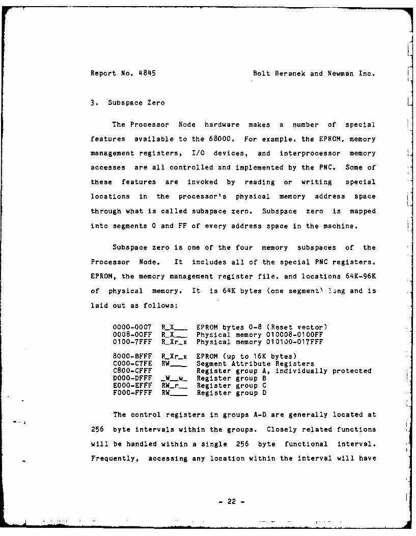
3. Subspace Zero
The Processor Node hardware makes a number of special
features available to the 68000. For example. the EPROM, memory
management registers, I/O devices, and interprocessor memory
accesses are all controlled and implemented by the PNC. Some of
these features are invoked by reading or writing special
locations in the processor's physical memory address space
through what is called subspace zero. Subspace zero is mapped
into segments 0 and FF of every address space in the machine.
Subspace zero is one of the four memory subspaces of the
Processor Node. It includes all of the special PNC registers.
EPROM, the memory management register file. and locations 64K-96K
of physical memory. It is 64K bytes (one segment) !.ng and is
laid out as follows:
0000-0007 R X- EPROM bytes 0-8 (Reset vector)0008-OOFF R X- Physical memory 010008-010OFF0100-7FFF RXrx Physical memory 010100-017FFF
8000-BFFF RXr-x EPROM (up to 16K bytes)COOO-C7FE RW- Segment Attribute RegistersC800-CFFF Register group A, individually protectedDOOO-DFFF _W-w_ Register group BEOOO-EFFF RW_r__ Register group CFOOO-FFFF RW. Register group D
The control registers in groups A-D are generally located at
256 byte intervals within the groups. Closely related functions
will be handled within a single 256 byte functional interval.
Frequently, accessing any location within the interval will have
- 22 -

1Report No. 4845 Bolt Beranek and Newman Inc.
the same effect as referencing the first location in the
interval. Bytes writes are generally not supported.
Figure 5 summarizes the available functions; most of these
are discussed in detail in individual sections below.
Several PNC functions use parameter blocks to pass arguments
to the PNC and return results from the PNC. There is a special
consideration in their use. The PNC checks that the program can
read and write the contents of the parameter block. Normally,
for this purpose, the 68000 Supervisor mode flag and the
Processor Node's Kernel mode flag are combined to yield a
composite "kernel mode". However, in the case of these parameter
blocks, the 68000 Supervisor mode flag is ignored. Since the
operating system uses the Kernel mode flag, there is no problem.
However, it is not good enough to assume that an interrupt
routine is in kernel mode unless the Kernel mode flag has been
set explicitly. A further consideration is that these parameter
blocks must be located in the local memory of the Processor Node.
3.1 EPROM
The specification for EPROM is straightforward, except that
the first 8 bytes appear at locations 0-7, as well as with the
rest of the the EPROM at location 8000 and up. This is so that
the reset interrupt vector is available at power-up. Space is
reserved in the address space for up to 16K bytes of EPROM. As
- 23 -

Report No. 4845 Bolt Beranek and Newman Inc.
Btran DOOG L _W__...w. Request block transfer
rtc EOOO L RW_r_. Read or set real time clock (62.5 usec)sltime E700 S _W_ Set interval timer (62.5 usec)
pnn E100 B RW_r_ Read or set Processor Node numberrrpnn E200 B R-r__ Last reset request's Processor Numberrrint E200 B _W_ Request remote interruptrreset E202 B _W_ Re quest remote reset
leavker E300 S R r_ Read ASAR. leave kernel mode, enable*ntker E302 S R-r__ Read ASAR. enter kernel modeAsAr E304 S RW_r_ Read or Write ASARenticerin E306 S R-....r__ Read ASAR, enter kernel mode, inhibit
PNC-post F300 L _W_ Post Event
PNC..enq E400 L _W_ Supervisor enqueue functionPNC-deq E404 L _W_ Supervisor dequeue functionPNC..push E40O8 L _W_ Supervisor push functionPNC_rem E40C L _W- Supervisor remove queue element functionPNC-cTx E41 0 L _W_..... Clear-then-xor bits in memoryPNC_cTa E414 L _W _ Clear-then-add bits in memory
dq-poll E500 L _W_ Poll dual queuedq-..deq E520 L _W_ Dequeue from dual queue: [event-to-post]dq..pdeq E560 L _W_ High-priority dequeue: [event-to-post)dq-fetch E580 L _W_ Fetch-an-event from dual queuedq-.erzq E5AO L _W_ Enqueue on dual queue: [any long)dq..stack E5EG L. _W_ Stack data on dual queue: [any long]
mSC E600 S _W_ Set PNC misc registerrdverri E400 S R-r_ Microcode version numberrdint FOOO S R____ Read INTrandint FOOO S -_ AND to IN Triorint F002 S _W_ 10R to IN Tr
mCr..PEH[J F100 S R - High word of parity error addressmCr..YEL[] F110 S R_ Low word of parity error addressmCr..CPE[] F120 S _W_...... Clear Parity errormCr..DAR[J F140 S _W_.. Disable Auto-Refresh
4mCr..EAR[J FiCO S _W_ Enable Auto-Refresh
PNCsRC F200 S R - Read and clear PNC status registerUprobe F200 L _W_ Check virtual address
Figure 5 *Control Registers
-24-
Report No. 4845 Bolt Beranek and Newman Inc.
long as an EPROM shorter than 16K is installed, additional images
of the EPROM will occur.
3.2 Subspace Zero Main-Memory
The region of physical memory from 10008 to 17FFF is mapped
by the hardware into addresses 0008 through 7FFF of subspace 0.
This supports the 68000 interrupt vectors (bytes 8-511) and the
operating system kernel including all interrupt handling
routines, the standard protected library routines, and other
standard library routines, as desired. To protect the vectors
and code, this region of subspace zero is given RXr-x access.
Of course, this memory may be mapped in with any protection by
the supervisor using subspace 2 or 3.
3.3 Segment Attributes Registers
There are 512 32-bit SARa, which appear at location COOO in
subspace zero. They can be read or written in kernel mode as
32-bit long integers or 16-bit integers; byte writes are not
supported (the same thing would be written into both bytes of the
word). The bit-wise layout of a SAR is shown in Figure 6.
- 25 -

Report No. 41845 Bolt Beranek and Newman Inc.
SEGMENT ATTRIBUTE REGISTER
N. S S -~--
Processor Page Bits 19:16Node Number Offset of the Physical
Address
Access Code Sgetsize
0 RLr-x 0 0 8 162 R-..Xr...x 1 1 9 244 RWXrwx 2 2 A 326 RW-rw.. 3 3 B 48 Subspace___
8 R-r 4 4 C 64 0 Subspace ZeroA RW... 5 6 D 96 4 1/0C R__ 6 8 E 128 8 Local MemoryE RWr.. 7 12 F 256 C Remote Memory
ADDRESS SPACE ATTRIBUTE REGISTER
I I I I I 1 .1 1 O O~
Kernel]SR
Inh IbisT
Size Code
0 82 164 32668 128A25M
SAR and ASAR LayoutFigure 6
-26-
Report No. 4845 Bolt Beranek and Newman Inc.
3.4 Address Space Attribute Register
The layout of the ASAR is shown in Figure 6. The Address
Space Attribute Register (ASAR) contains a number of important
fields, some of which can be set directly by the user.
Therefore. a user-mode method for setting and/or clearing these
fields is necessary.
The address space size field controls how many segments
appear in the current virtual address space (excluding segments
F8-FF which are always present). The sizes must be powers of
two; the coding is given in Figure 6.
The ASAR is an actual hardware register, but the microcode
keeps a copy of the ASAR in an alu register, and the function
which reads the ASAR actually references that register instead.
In kernel mode all 16 bits can be written with a single operation
by storing into the global variable AsAr. The ASAR can be read
at four different locations. However. all but AsAr have side-
effects which change the value of the ASAR just after the read
has occurred. Reading the variable leavker clears the Kmode and
intINH bits; entker sets the Kmode bit; and entkerin sets both
the Kmode and intINH bits. With these functions, the supervisor
can enter kernel mode or inhibit interrupts and save the previous
state indivisibly.
- 27 -

Report No. 4845 Bolt Beranek and Newman Inc.
3.5 Real-Time Clock/Timer
The PNC maintains a 32-bit time-of-day clock and a 16-bit
interval timer. The resolution of each clock is 62.5
microseconds, giving a maximum timer interval of 4.096 seconds
and a time-of-day period greater than 74 hours. The interval
timer initiates a 68000 interrupt on level 2 when it reaches
zero. At that time, it is reset to request a new interrupt in
4.096 seconds.
These two functions use two internal registers that record
the time-till-next-interrupt (in a PNC register) and time-of-
next-interrupt (in main memory); their difference is the current
time-of-day. The value of the time-of-day is available to the
user and system as rtc. Since rtc is two words long and can
change at any time, care must be taken to read it reliably. The
68000 must execute a "movl rtc, <ea>" instruction which takes two
memory cycles. During the first cycle the PNC calculates the
correct 32-bit time. returns the high word, and stores the low
word into an internal PNC register. During the second cycle it
simply returns the value from that register. Most of the
operations that are done on longs by the 68000 operate in the
correct order. However, pushing arguments on the stack accesses
the words in the wrong order so one should not pass rte directly
as an argument to a function.
- 28 -
Report No. 4845 Bolt Beranek and Newman Inc.
To set the timer interrupt interval, store the number of
62.5 microsecond ticks in the interval, as a short unsigned
integer, into sltime. Only requests which reduce the current
interval are honored. When a timer interrupt occurs, the 68000
should first clear the interrupt request (see niR2 in the INTr),
then reset the timer if desired.
Because of a bug in the current microcode, the programmer
must be careful not to store a zero into the timer since this
will cause the real time clock to loose 4 seconds and the timer
to be reset to expire in 4 seconds. This will be fixed in the
future.
It is also tricky to set rtc reliably. Since this is a rare
event, we do not try to solve this problem directly in the
microcode; instead, a special procedure must be used by the
68000:
The 68000 executes a 'movl' instruction to locationffeOOO (rtc); this will cause two memory cycles, thefirst to write ffeOOO, the second to write ffeO02.During the first cycle we simply store the high word inclknext. During the second cycle we add in the time-till-next-interrupt and store the result in clknext+2;the carry. if any, is ignored. That means that ouranswer is wrong if there was a carry, or if theinterval timer was incremented between the two cyclesand a carry occurred. The 68000 program MUST check forthis by reading the time-of-day clock and comparing thetime it tried to set with the time read; if they arenot within a few ticks of each other this process mustbe repeated.
-29-

Report No. 4845 Bolt Beranek and Newman Inc.
3.6 Block Transfer
A microcode supported block transfer facility is available
to transfer a block of data from one location to another. The
68000 program activates this facility by writing the address of a
parameter block with the following format into Btran.
struct btrctrl /* block transfer control block 1/(char *btto; /* virtual address of destination '/short unsigned bt-len; /0 length of transfer in bytes [minus 1]char *bt.from; /* virtual address of source 1/
1;[ byte count minus one (16 bits, unsigned, but 0 <= bc-i < Ox8 00) J
The protection mechanisms require that the transfer not
cross a segment boundary and not be to or from I/O or subspace
zero. It must also be legal for the 68000 to read and write into
the parameter block and to write into the destination area and
read from the source area. These tests are performed using the
mode the 68000 had when it specified the parameter block.
Protection violations generate a bus error.
There may be from one to three processors involved in a
single block transfer. During a block transfer the source and
destination processors will be quite busy. since the switch will
try to use 3/4 of the total PNC bandwidth in these processors.
I/O transfers have priority over block transfers, but 68000
memory access requests do not, and the 68000 will run a great
deal slower than normal during a block transfer. If the
processor which requested the block transfer is not involved in
-30-

Report No. 4845 Bolt Beranek and Newman Inc.
passing the data, it simply continues normally until it does
another switch operation which interacts with the block transfer.
Because block transfers can use so much switch and processor
bandwidth, it is important to consider their impact on other
switch traffic and system latencies. The most common result of
excessive contention in the switch is that some messages will be
delayed past the timeouts which normally detect broken or missing
hardware. These timeouts are currently set to about 10
milliseconds. If they are exceeded level 7 interrupts result.
In an attempt to help reduce switch contention problems, the
originating processor must break up long block transfer requests
into a series of shorter requests, so that other switch traffic
will have a chance to get through. This is done by the library
routine that handles block transfers.
3.7 Post Event
Events are the central operating system process control
primitive. They may be posted to notify a process of some
interesting happening in the machine. ro post an Event, the
68000 writes the address of a parameter block into PNCpost. The
* parameter block is specified as follows:
TT - 31 -
* - 7 • I ... ... .. .. - _
Report No. 4845 Bolt Beranek and Newman Inc.
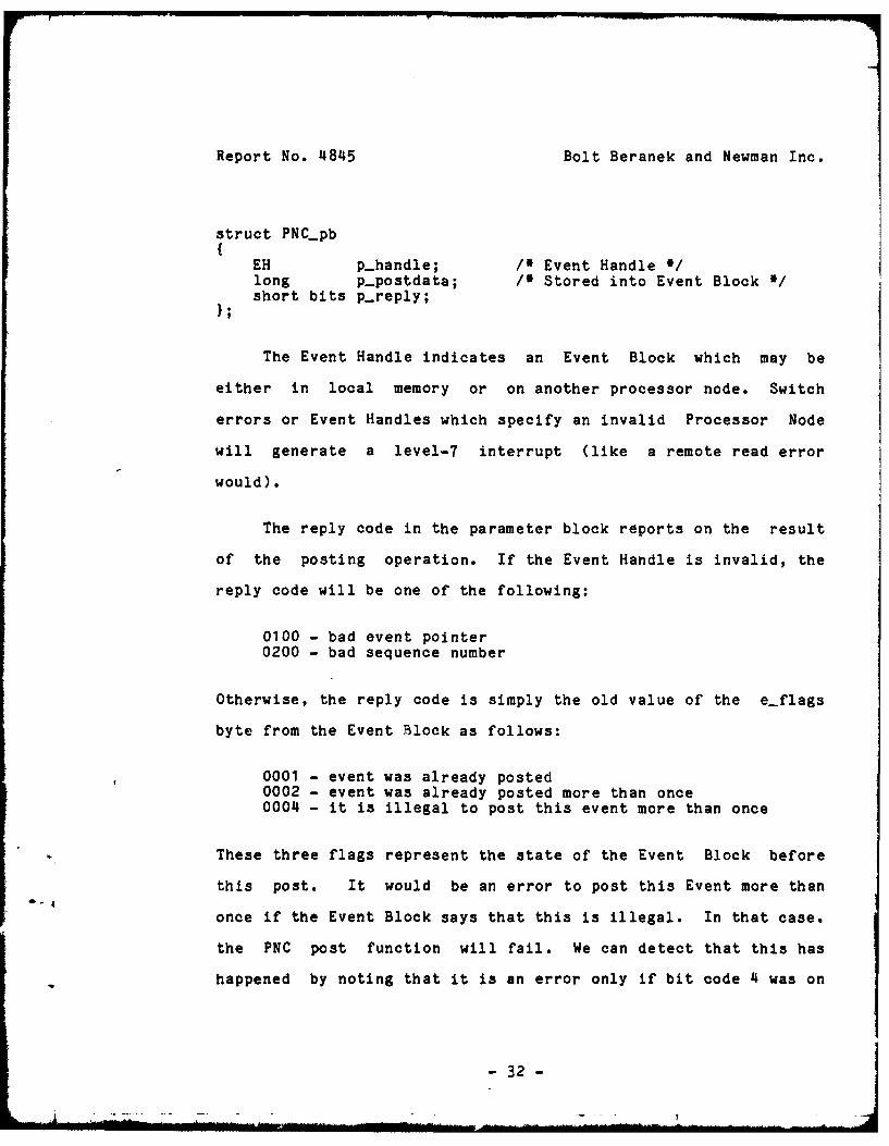
struct PNC.pb{EH p-handle; / Event Handle '/long p.postdata; / Stored into Event Block */short bits p-reply;1;
The Event Handle indicates an Event Block which may be
either in local memory or on another processor node. Switch
errors or Event Handles which specify an invalid Processor Node
will generate a level-7 interrupt (like a remote read error
would).
The reply code in the parameter block reports on the result
of the posting operation. If the Event Handle is invalid, the
reply code will be one of the following:
0100 - bad event pointer0200 - bad sequence number
Otherwise, the reply code is simply the old value of the e-flags
byte from the Event Block as follows:
0001 - event was already posted0002 - event was already posted more than once0004 - it is illegal to post this event more than once
These three flags represent the state of the Event Block before
this post. It would be an error to post this Event more than
once if the Event Block says that this is illegal. In that case,
the PNC post function will fail. We can detect that this has
happened by noting that it is an error only if bit code 4 was on
- 32 -
IReport No. 4845 Bolt Beranek and Newman Inc.
and one of the other bits was also on. Combining the error codes
from above and this constraint, we can see that reply codes O-4
are normal. while codes 5 and above indicate various error
conditions.
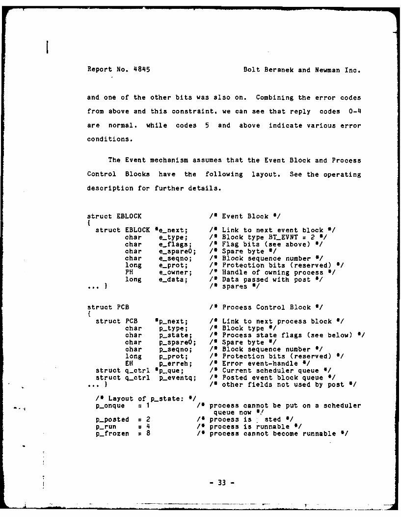
The Event mechanism assumes that the Event Block and Process
Control Blocks have the following layout. See the operating
description for further details.
struct EBLOCK /I Event Block /(struct EBLOCK 'e.next; /I Link to next event block V
char etype; / Block type BT_EVNT = 2 /char e-flags; /* Flag bits (see above) /char e-spareO; /* Spare byte */char e-seqno; /* Block sequence number */long e-prot; / Protection bits (reserved) iPH e-owner; /* Handle of owning process i/long e-data; /I Data passed with post i
} / spares /
struct PCB /* Process Control Block 'l{struct PCB *p.next; /I Link to next process block i
char p-type; /I Block type */char p-state; /* Process state flags (see below) /char p-spareO; /* Spare byte '/char p.seqno; /* Block sequence number /long p-prot; /* Protection bits (reserved) 0/EH p-erreh; /* Error event-handle */
struct q.ctrl 'p.que; /* Current scheduler queue */struct q.ctrl p.eventq; /* Posted event block queue /
.. } /I other fields not used by post /
/0 Layout of p.state: /p-onque = 1 /* process cannot be put on a scheduler
queue now */p.posted = 2 /0 process is sted /p-run = 4 /0 process is runnable 0/p-frozen = 8 /0 process cannot become runnable /
-33-ILI
Report No. 4845 Bolt Beranek and Newman Inc.
In addition to these data structures. the post microcode
also depends on CurQ, a pointer to the currently active scheduler
queue, and on the layout of the array of scheduler queues, to
decide whether to invoke the scheduler.
The actual algorithm used to post an Event is as follows:
1. Check the block type in the specified event block2. Check the sequence number in the specified e'ent block3. Test if the event block is already posted; if so:
3.1 Set posted-more-than-once flag3.2 Return 'was-posted' or 'illegal-multiple-post' reply
4. Set event-posted flag; store user data in event block5. Enqueue the event on the owner's event queue6. Set process-posted flag and process-on-queue flag7. If process-on-queue flag was set, return normal reply8. Compare priority of queue with running-process-queue;
set interrupt level 1 if context switch is required9. Enqueue the process on the proper scheduler queue10. Return normal reply.
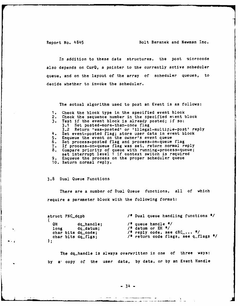
3.8 Dual Queue Functions
There are a number of Dual Queue functions, all of which
require a parameter block with the following format:
struct PNC.dqpb /* Dual queue handling functions */{
QH dq-handle; /* queue handle */long dq-datum; /* datum or EH *char bits dq.ode; /0 reply code, see dRC_ ... *1char bits dq-flgs; /0 return code flags, see q-flags */
- , };
The dq-handle is always overwritten in one of three ways:
by a- copy of the user data, by data, or by an Event Handle
- 34 -
Report No. 4845 Bolt Beranek and Newman Inc.
extracted from the Dual Queue. In the cases when an Event Handle
is returned, this allows the 68000 to post it immediately, using
the same parameter block.
The Dual Queue may be on any Processor Node in the machine.
If the Processor Node portion of the handle is invalid, the
switch error will generate a level-7 interrupt (like a remote
read would).
The various dual queue functions are enqueue. dequeue,
stack, priority-dequeue, fetch (an event), and poll (for data).
These functions and other dual queue features are specified
below.
dq-poll Poll dual queuedq-deq Dequeue from dual queue: [event-to-post]dqpdeq High-priority dequeue: [event-to-post]dq-fetch Fetch-an-event from dual queuedq-enq Enqueue on dual queue: [any long]dq-stack Stack data on dual queue: [any long]
It is important to distinguish between the enqteue/dequeue
functions, as requested by the 68000 and the Chrysalis system
calls which use these functions. It is also important to
distingui between the dequeue function and the extract
operation. If data is available, the dequeue function invokes
the extract operation; otherwise it uses the insert operation.
The same is true for the the enqueue operation, which may do
either an insert or an extract.
-35-

Report No. 4845 Bolt Beranek and Newman Inc.
Dual queues have two sections, a queue header (see layout
below) and a ring buffer. The ring buffer may have either data
entries or Event Handles, or may be empty. A flag bit in the
queue header distinguishes data queues from Event queues. A
queue may be frozen by its owner (for debugging purposes, etc.),
by setting a flag bit; in this case all dual queue requests
return the 'frozen' reply code.
When dual queues are used as locks, an empty queue
represents a locked lock; to unlock the lock, the process which
is holding the lock uses enqueue to store something on the queue
(actually its Process Handle is stored as a debugging aid).
Anyone who needs the lock can use dequeue to wait for the lock,
or poll to test the lock. Setting the 'lock' flag bit limits the
queue to a maximum of one data entry at a time. and thus prevents
inadvertently unlocking a lock more than once.
PNC Dual Queue return codes (high byte). The low byte is thenew value of q.flags, except for errors:
dRCFRZN = 0000 ;reply: frozendRCBQH = 0100 ;error: bad queue handledRC_SNE = 0200 ;error: sequence number errordRC_MUNLK = 0400 ;reply: attempt to multiply unlock (enq)dRC_FULL = 0800 ;reply: queue is full (enq/stack/deq)dRC_EMTY = 1000 ;reply: queue is empty (fetch/poll)dRC_EXTRT = 2000 ;reply: extracted a queue entrydRC_INSRT = 4000 ;reply: inserted a queue entry
- 36 -

IReport No. 4845 Bolt Beranek and Newman Inc.
Queue Header layout (also see operating system documentation):
struct DUALQUE(struct DUALQUE *q-next; /* Link to next queue header '/
char q-type; /* Block type BTDQH = 6 £/char q-flags; / Flag bits (see above) /char q-spareO; / Spare byte '/char q-seqno; / Block sequence number Vlong q-prot; / Protection bits (reserved) VEH q-ownevnt; /* Owner's Event Handle /short q-exadd; /1 Extract address *Ishort q inadd; /* Insert address 'Ishort q-endadd; / End-of-queue address (last+4) /short q-stadd; / Start-of-queue address 'Ichar q-sparel; /* Spare byte */char q-queueh; / Queue address bits 19.16 /long q-lastext; /* At time of last extract: element
which would have been inserted /
long q-exttime; / Time of last extract 'Ilong qinstime; / Time of last insert */
Bits in q-flags:
q-frozen = 8 ;queue is frozen by ownerq lock = 4 ;queue may have only one data entry
= 2 ;must be zero!q-events = 1 ;queue has events (otherwise has data)
A library routine is used to initialize a dual queue. This
routine allocates a queue header and a block of memory for the
ring buffer. The ring buffer must be allocated within a single
64K block. The physical address of the first word is stored in
q queueh and qstadd. Copies of q stadd are stored in qexadd
and q-inadd. The ring length must be an exact multiple of 4
bytes; q-stadd plus the ring length is stored in q-endadd. To
determine the size of the ring buffer, it is necessary to
determine how many objects may be present and how many processes
may be waiting in the Dual Queue. The queue must be large enough
-37
Report No. 4845 Bolt Beranek and Newman Inc.
to support the larger number of items. Each item is 4 bytes long
and space for one item is unused. As a result, the minimum ring
length is 8 bytes.
The dual queue mechanism includes a number of debugging aids
of which the user should be aware. These include the various
legality and overflow checks mentioned above; in addition. the
microcode records the time of last insert and of last extract.
and the identity of the last extractor. When using poll you
should supply an Event Handle, as you would for dequeue. to keep
the debugging information valid. You should supply your process
handle whenever you use fetch, and when you use enqueue to unlock
a lock. A function which examines the current status of a lock
and prints its recent history will be provided to help in
debugging.
The actual Dual Queue algorithm is as follows:
1. Check the block type in the specified queue header.2. Check the sequence number in the specified queue header.3. If the dual queue is frozen, return 'frozen' reply.4. Decode the function requested and the queue state to decide
whether to try to extract an entry or to insert an entry.
To extract:5x. If queue is empty;
reverse queue state and try to insert instead (go to 6i).6x. If last entry in ring,
reset extract address to start of ring.7x. Save the user-data for debugging purposes.8x. Extract an entry.9x. Update the time-of-last-extract.
10x. Return entry with 'extracted something' reply code.
-38-

Report No. 4845 Bolt Beranek and Newman Inc.
To insert:5i. If data queue is not empty and this is a lock:
return 'multiple unlock' reply code.6i. Test if this is a 'polling' or 'fetch' request; if so,
return 'empty' reply code.7i. Test if inserting at the beginning or end of the queue.8i. Update the appropriate ring pointer, unless the queue was
full, otherwise return 'full' reply code.9i. Insert the user data.
10i. Update the time-of-last-insert.11i. Return 'inserted something' reply code.
3.9 Various Kernel Functions
This section describes microcode functions that involve
kernel mode access to control blocks or other data in physical
memory, in the range 0-64K bytes (segment F8). Manipulation of
true virtual addresses is not possible in these functions, and
only very limited error checking is provided. To initiate one of
these functions, the supervisor provides the 24-bit virtual
address of a parameter block in local memory (subspace two), via
a movl instruction. The block will have various formats,
depending on the function involved. Sometimes results are
returned in the parameter block, and sometimes various data
structures are modified. If errors are possible, error codes are
returned in the parameter block. The functions run as
uninterruptable units, which is their primary reason for
existence; their speed advantage, though possibly significant, is
secondary.
- 39 -

Report No. 4845 Bolt Beranek and Newman Inc.
The following functions are avail-able, depending on where
the address of the parameter block is stored:
Name Function
PNCenq Enqueue block on the end of a queuePNCdeq Dequeue(pop) block from the beginning of a queuePNC.push Push block onto the beginning of a queuePNCrem Remove specified block from anywhere on a queuePNC.oTx Clear-then-xor specified bits in memory word;
save old valuePNCcTa Clear-then-add specified bits in memory word;
save old value
In the specification of control blocks, starred parameters
(II) are parameters which are returned by the microcode, as
opposed to normal parameters which are supplied by the
supervisor.
3.9.1 Enqueue, dequeue, push. remove
The scheduler queueing functions expect queued items to have
following format:
word at 0: xxword at 2: address of the next element on the queue.
or 0. which indicates that this is the last elementwords at 4: arbitrary data
The microcode uses only the word at byte 2. The enqueue and push
functions set and maintain the contents of that word; dequeue and
remove use it, but do not modify it. The data in word zero is
established and used only by the 68000 code. The same is true
for all words specified as 'xx' in the other data structures
- 40 -

IHReport No. 4845 Bolt Beranek and Newman Inc.
specified below.
The queue header:
word at 0: xxword at 2: address of the first element on the queue,
or 0, which indicates that the queue is emptyword at 4: xxword at 6: address (0-64K) of the last element on the queue,
or garbage if the queue is empty
The parameter block for the enqueue/push functions:
word at 0: xxword at 2: address of the queue headerword at 4: xxword at 6: address of the element to add
The parameter block for the dequeue(pop)/remove functions:
word at 0: xxword at 2: address of the queue headerword at 4: xxword at 6: address of the element dequeued,'*
or 0, which indicates that the queue was empty**(for remove, this address is supplied by the 68000,and is cleared if the element is not found**)
No validity checking is attempted for these parameters.
3.9.2 Clear-Then-XOR and Clear-Then-Add
The clear-then-xor PNC.oTx and clear-then-add PNCoTa
functions are used to modify a word in supervisor memory and read
back the old value at the same time. They are mostly used to
solve potential interrupt bugs. The old word is read from memory
and stored in the parameter block. Then the bits specified in
the parameter block mask word are cleared from the value of old
- 41 -
Report No. 4845 Bolt Beranek and Newman Inc.
word, the parameter block data word is xor'ed (or added) to the
result, and the word is stored back into memory.
The parameter block for the clear-then functions has the
following format:
word at 0: xxword at 2: address of the word to modifyword at 4: a word which contains the mask of bits to clearword at 6: a word which contains bits to xor or add to memoryword at 8: old value of the word specified**
Note that this can be used to exchange bits, bytes, or entire
words; it can also be used to xor, and, ior. and add to memory,
etc. It is an extension of the idea of using exchange to provide
indivisibility.
3.10 Misc register
The PNC misc register has two sections:
bits 7.4 - path enable selection, paths 3.0bits 3.0 - header checksum. bits 3.0
This register can only be set as a unit by the 68000, so the
operating system should maintain a shadow copy to enable the
fields to be updated separately.
-42-

j Report No. 4845 Bolt Beranek and Newman Inc.
3.11 Interprocessor Interrupts and Resets
To request a remote processor level-7 interrupt, store the
processor number, as a byte, into rrint. This is not really
useful as a high-bandwidth signaling mechanism, since the remote
processor's supervisor pushdown list could overflow if too many
level-7 interrupts arrived at once.
To request a remote processor reset, store the processor
number, as a byte, into rreset. Note that this will completely
destroy the state of the remote 68000 and PNC, and will restart
the remote operating system. Although main memory will be
preserved by the reset, parts of it will be reused by the
operating system during the restart; therefore, important
debugging information may be lost. The reset will always
succeed, except in the presence of broken hardware. It should be
used only in emergencies. The identity of the processor which
last reset a given processor can be read, as a byte. from rrpnn
in the processor which was reset.
3.12 Interrupt Control Register
The interrupt control register (INTr) contains a number of
independent bits, some of which can be set directly by the PNC.
Therefore. non-interruptable methods for setting and clearing
these bits are necessary. This is the INTr layout (a leading n
or means the function is active when the bit is zero):
-43-
Report No. 4845 Bolt Beranek and Newman Inc.
bit 7 - nliteLED red LED on PNC boardbit 6 - rand stop the randomizer clockbit 5 - niR5 -68000 level 5 interrupt requestbit 4 - niR2 -68000 level 2 interrupt requestbit 3 - niR1 -68000 level 1 interrupt requestbit 2 - (Reserved) Used by the PNC - do not changebit 1 - (Reserved) Used by the PNC - do not changebit 0 - niR7 -68000 level 7 interrupt request
Data written into the variable andint is bitwise ANDed into
the INTr, while data written into orint is bitwise ORed into the
INTr; these functions allow bits to be set or cleared with no
chance of error due to interrupt bugs. A 68000 IOR-to-memory
instruction would not work since the PNC might modify the INTr
between the 68000 read and rewrite cycles.
All 8 bits are saved in the low byte of an alu register, and
an attempt to read the INTr actually references that register
instead; the register is also used to restore the real INTr after
certain protection checking functions in the microcode. We plan
to use the high-order byte of the INTr to report certain error
conditions detected by the PNC of the type which do not cause
level 7 interrupts, thus expanding the PNC status register by
eight bits. [This is simply a warnirg of things to come.]
The microcode reset code ;urns on the LED and clears all
interrupts; once the local operating system has successfully
joined the global operating system, it turns off the light to
indicate that the node is in service. If the node goes out of
service the light will be turned on to indicate which Processor
- 44 -

IReport No. 4845 Bolt Beranek and Newman Inc.
INode is having the problem.
I The switch randomizer must be initialized to a different
point in each Processor Node. This is done during initialization
by turning off the clock to the switch randomizer with rand for a
time proportional to the Processor Node number.
Bits 1 and 2 are used exclusively by the microcode; do not
tamper with them.
Bits 0, 3, 4, and 5 control interrupts to the 68000. If any
of these bits are cleared, an interrupt is caused on that
interrupt level. Except for level-7 interrupts, the operating
system must logically clear (really set) the appropriate
interrupt request bit in each interrupt service routine,
otherwise the interrupt will immediately recur when the routine
terminates. Level-? requests are automatically cleared by the
PNC (or the 68000) just as the interrupt routine is being
initiated; thus the level-? handler must be written to be
reentrant, and level-7 events which occur while the handler is
running will cause nested interrupts -- otherwise such events
might be lost completely.
Note that interrupt requests can be lost if a second request
o occurs before the previous request at the same level has been
serviced. You are safe if you do not initiate any action which
could result in an interrupt until you have logically cleared the
-. corresponding interrupt bit.
I45
Report No. 4845 Bolt Beranek and Newman Inc.
There is a microcode routine which provides an interrupt
vector to the 68000 for all external interrupt conditions. The
68000 requests a vector for a specific interrupt level. Levels
1,2.5,6,7 are assigned in the microcode to coincide with the68000 'Interrupt Auto-Vector' of the corresponding level (see the
68000 manual, page 5-5). Levels 3 and 4 use an interrupt vector
provided by an I/O board (if valid, otherwise the Auto-Vector is
used). The full 16-bit interrupt vector supplied to the 68000 is
stored by the microcode in the intVEC array in main memory, with
one entry per interrupt level [1-7J. Currently, this array is of
little interest except for I/0 interrupts.
3.13 Microcode Version Number
Each version of the microcode PROMs will have a distinct
version number which can be read by the 68000 as rdvern. This
version number is specified in the revision line on page 1 of the
microcode listing. When a new set of PROMs is created it will be
assigned a number P and will initially have the version number
OxPO00. Each time the PROMs are patched, a bit will be set in
the low 12 bits of the version number, starting from the right.
For example, PROM set seven will begin as version OxTOO (7.000);
as it is patched its version number will change to 7.001, 7.003,
7.007, 7.OOF, etc.
-46-

IReport No. 4845 Bolt Beranek and Newman Inc.
3.14 Memory Control Registers
JUp to 4 memory boards may be attached to a Processor Node.
Each board contains several control registers. The variables
that control these boards are actually arrays where the subscript
indicates which board is being addressed. For example, to clear
the parity error on board 2. the programmer writes into
mCrCPE[2]. It does not matter what is written into this
variable.
These boards are able to detect parity errors and to report
the address that contains the error. When a parity error is
detected, the physical address (bits 18.0) is saved in mCrPEH
and mCrPEL, the sign bit of mCrPEH is set. and an interrupt is
requested on level 6. The data in these words is not valid
unless the sign bit is set. The sign bit is cleared by writing
anything into mCrCPE.
The dynamic memory chips used on the memory boards must be
refreshed to maintain their data. Normally the PNC does this,
but when power fails, the PNC stops. To prevent loss of data,
battery power may be provided to the memory boards, and special
auto-refresh circuitry may be enabled to support the memory ohile
the rest of the Processor Node is turned off. A memory board
will not do normal read or write operations while in auto-refresh
mode. mCrDAR is used to disable auto-refresh and mCr_EAR is
used to enable it. The proper procedure to be followed during a
-47-I-
Report No. 4845 Bolt Beranek and Newman Inc.
reset is described under the section on the PNC Status Register.
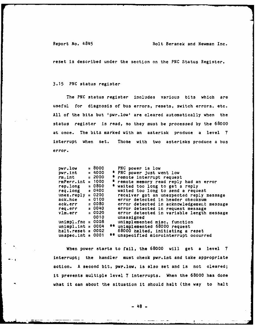
3.15 PNC status register
The PNC status register includes various bits which are
useful for diagnosis of bus errors, resets, switch errors, etc.
All of the bits but Ipwr.lowt are cleared automatically when the
status register is read, so they must be processed by the 68000
at once. The bits marked with an asterisk produce a level 7
interrupt when set. Those with two asterisks produce a bus
error.
pwr.low = 8000 PNC power is lowpwr.int = 4000 * PNC power just went lowrm.int = 2000 * remote interrupt requestrmPerr.int = 1000 * remote memory read reply had an errorrep.long = 0800 ' waited too long to get a replyreq.long = 0400 waited too long to send a requestunex.reply = 0200 receiver got an unexpected reply messageack.hce = 0100 error detected in header checksumack.err = 0080 error detected in acknowledgeme.t messagereq.err = 0040 error detected in request messagevlm.err = 0020 error detected in variable length message
0010 unassignedunimpl.fnc = 0008 unimplemented misc. functionunimpl.int = 0004 I unimplemented 68000 requesthalt.reset = 0002 68000 halted, initiating a resetunspec.int = 0001 ' unspecified microinterrupt occurred
When power starts to fail, the 68000 will get a level 7
4 interrupt; the handler must check pwr.int and take appropriate
action. A second bit, pwr.low, is also set and is not cleared;
it prevents multiple level 7 interrupts. When the 68000 has done
what it can about the situation it should halt (the way to halt
- 48 -

Report No. 4845 Bolt Beranek and Newman Inc.
is to make the supervisor push-down list inaccessible, then cause
a bus error). The microcode will set halt.reset, clear all the
other bits, put memory in auto-refresh mode, and start to reset.
Resetting cannot succeed until power is normal again; if power
goes all the way down and comes back later, the power supply will
initiate a new-power type reset, which will clear halt.reset.
3.16 Verify User Write-Access
When the supervisor stores data at an address provided
directly by a user, it must ensure that the user has the right to
modify that location. It can do this by first storing the
ADDRESS (as a long) into Uprobe. The microcode will determine if
the address would have been legal for a user-mode nonkernel
write, and will otherwise generate a bus error. Addresses in
subspace zero will always generate bus errors, which prevent this
type of store from directly triggering PNC functions, whether or
not such a function would have been legal for the user to reques'*
independently.
For example, imagine a kernel-mode subroutine which stored
the location of a block of data at an address specified by a user
program. If the user specified the address ffdOOO, and the
subroutine did the store without checking, the block transfer
microcc - would be invoked, and it would interpret the address as
the location of a control block specifying block transfer
4

Report No. 4845 Bolt Beranek and Newwan Inc.
para ',ters. Even though the block transfer function checks its
parameters for validity, those checks might well be defeated by
the fact that the subroutine is in kernel mode, and thus valuable
information might be destroyed. Thus the need for checking is
established. Using the checking function solves this problem.
since the address supplied by the user is in subspace zero, and a
bus error is generated during the check function, before the
store instruction is executed in the subroutine.
The checking function considers all addresses in subspace
zero to be illegal for the following reason. Assume instead that
it allowed access to addresses which the user himself could have
accessed. Since the user can write into the address which
triggers a block transfer directly, the previous example would
pass the tests, and still potentially destroy information. More
subtle tests seem impractical in the microcode. If the
restriction that all subspace zero addresses are illegal is
unacceptable in a particular case, it is always possible to leave
kernel mode before doing the requested store operation, and
reenter as necessary.
3.17 Conclusion
This document describes microcode version 1.003 (see
Section3.13). The microcode occupies approximately 3/4 of the
1024 available words of micromemory. The unused space may
- 50 -

Report No. 4845 Bolt Beranek and Newman Inc.
eventually be used for additional PNC functions that will speed
up the system or provide additional functions. Some prime
candidates include the process multiplexer (currently in assembly
language), object management functions, and floating-point
control functions.
The functions described here are the lowest level facilities
of the Processor Node. Many of them will never be seen by the
application programmer since they are used by higher level
operating system functions. We expect to describe those
functions in a future technical report.
5
I
I. - 51 -
Report No. 4845 Bolt Beranek and Newman Inc.
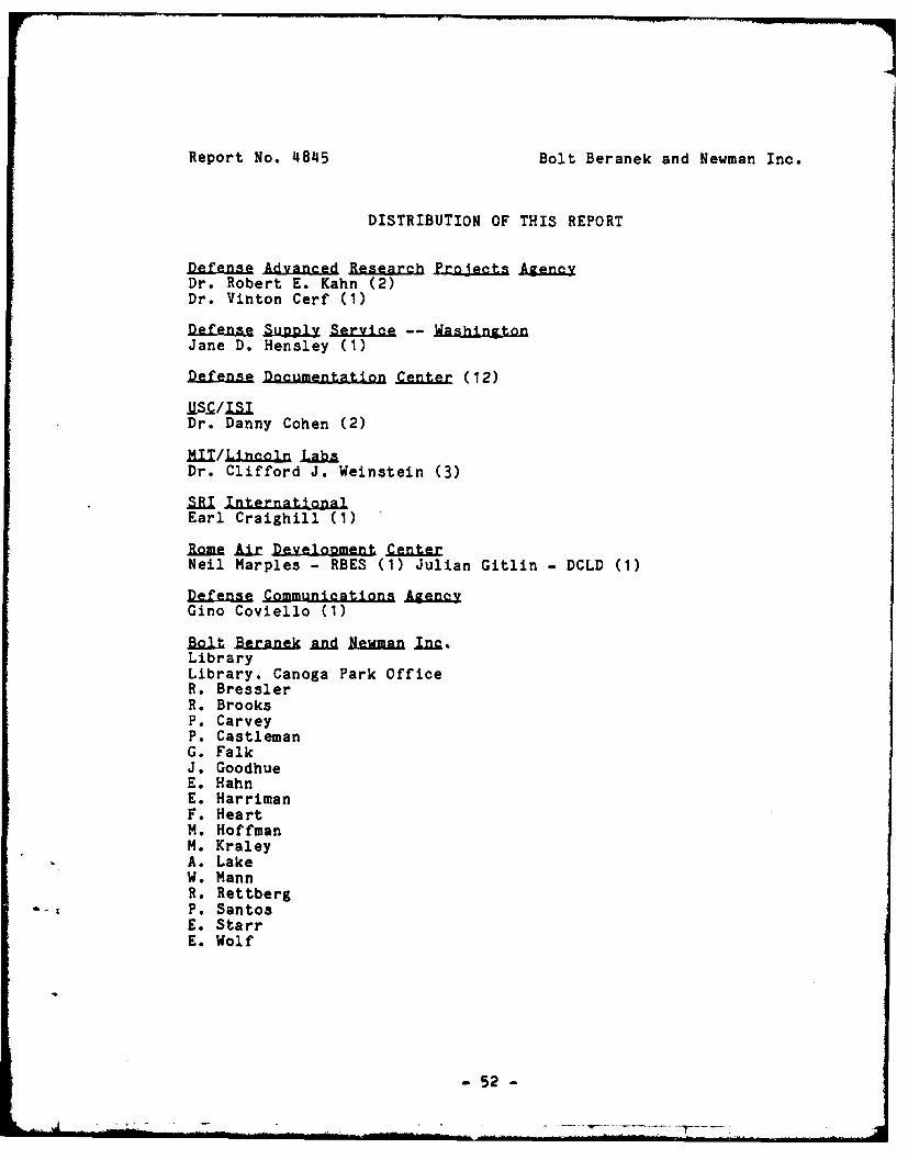
DISTRIBUTION OF THIS REPORT
Defens Ada Reearch Prje AgncyDr. Robert E. Kahn (2)Dr. Vinton Cerf (1)
D s Supply Service -- ahinLtonJane D. Hensley (1)
Defense Documentation Center (12)
Dr. Danny Cohen (2)
1=iT/~nln lab"Dr. Clifford J. Weinstein (3)
SR. InternationalEarl Craighill (1)
Romp Ar Dv t itolmln Cent erNeil Marples - RBES (1) Julian Gitlin - DCLD (1)
Defense Communications AgengyGino Coviello (1)
Ik Branek a-d Newman in.LibraryLibrary. Canoga Park OfficeR. BresslerR. BrooksP. CarveyP. CastlemanG. FalkJ. GoodhueE. HahnE. HarrimanF. HeartM. HoffmanM. KraleyA. LakeW. MannR. RettbergP. SantosE. StarrE. Wolf
- 52 -
' - . . . . . . III .. . . . " . . . ... . . . .. . . .. . . . . . .. '. . .. . .. . . . ... .

Report No. 4845 Bolt Beranek and Newman Inc.
INDEX
ASR............................. 25, 27
Btran.Ot ... o...........f*..... 40.000............... 24, 30
KurQode........... .oo..*oooe.*..... o@....... e.....Sooo 27
PNCd.............................69.0......... 0*. Qo 24,3
PNC-rem............................................ 24, 404PNCsRc............................................... 24 1SAR.................................................... 254
Penr............................ .. *so. 24, 27
inN .......... 2......................o.. 273iornt.............................*s*... .... . 2441Nek .............................................. 24, 27
mis..................................................... 24
pnn....o.....oe........ o.e..o...........*...............*. 24
Urit................................ 244rndven........................................ ...... 24, 46
dq eq........... .-53- 3dq~~ ...-. o .. -.. -s 24-3
Report No. 48A45 Bolt Beranek and Newman Inc.
rt . . . . . . . . . .. . . .. . . . . . . . . . . . 2 , 2
24, 29
-514 -