approved components list foundry
TRANSCRIPT
Approved Components List
Foundry
For the Manufacture of
The Volkswagen Group
„Technology-Specific Part“
Version date: 01. January 2021:
Version 2.3
Bosch_Rexroth_AG_Freigabeliste_VW_Components_Hydraulik_Giesserei_202001_en.docx
Version 2.3 / 01.01.2021 KSU-Klasse 6.1 Page 1 of 28
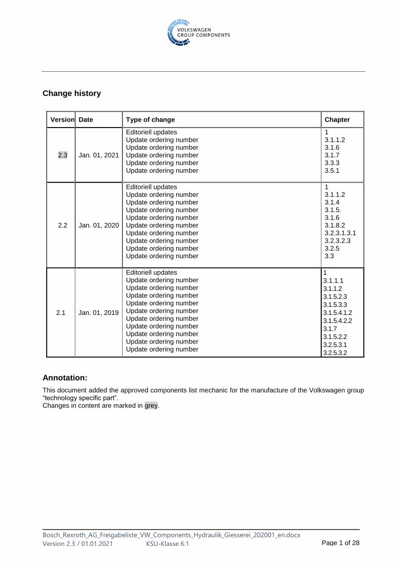
Change history
Version Date Type of change Chapter
2.3 Jan. 01, 2021
Editoriell updates Update ordering number Update ordering number Update ordering number Update ordering number Update ordering number
1 3.1.1.2 3.1.6 3.1.7 3.3.3 3.5.1
2.2 Jan. 01, 2020
Editoriell updates Update ordering number Update ordering number Update ordering number Update ordering number Update ordering number Update ordering number Update ordering number Update ordering number Update ordering number
1 3.1.1.2 3.1.4 3.1.5. 3.1.6 3.1.8.2 3.2.3.1.3.1 3.2.3.2.3 3.2.5 3.3
2.1 Jan. 01, 2019
Editoriell updates Update ordering number Update ordering number Update ordering number Update ordering number Update ordering number Update ordering number Update ordering number Update ordering number Update ordering number Update ordering number
1
3.1.1.1
3.1.1.2
3.1.5.2.3
3.1.5.3.3
3.1.5.4.1.2
3.1.5.4.2.2
3.1.7
3.1.5.2.2
3.2.5.3.1
3.2.5.3.2
Annotation:
This document added the approved components list mechanic for the manufacture of the Volkswagen group “technology specific part”. Changes in content are marked in grey.
Bosch_Rexroth_AG_Freigabeliste_VW_Components_Hydraulik_Giesserei_202001_en.docx
Version 2.3 / 01.01.2021 KSU-Klasse 6.1 Page 2 of 28
Table of contents
Change history ................................................................................................................................. 1
1 Contacts ............................................................................................................................ 4
2 Notes ................................................................................................................................. 5 2.1 Usage ................................................................................................................................ 5 2.2 General information .......................................................................................................... 5
3 Overview ........................................................................................................................... 7 3.1 Pump station with tank and accessories .......................................................................... 7 3.1.1 Pumps ............................................................................................................................... 7 3.1.1.1 Fixed displacement pumps – internal gear pumps ........................................................... 7 3.1.1.2 Variable displacement pumps – axial piston pumps ......................................................... 7 3.1.2 Reservoir ........................................................................................................................... 8 3.1.2.1 Reservoir 100 to 1000 l (DIN-24339, type BN, cover type A) ........................................... 8 3.1.3 Air Breather ....................................................................................................................... 8 3.1.4 Pressure measurement and indicating devices ................................................................ 8 3.1.5 Filters ................................................................................................................................ 9 3.1.5.1 Clogging indicator ............................................................................................................. 9 3.1.5.2 Inline filter in return flow .................................................................................................... 9 3.1.5.2.1 Filter bowl can be unscrewed to the bottom: Standard pressure rating 250 bar .............. 9 3.1.5.2.2 Filter bowl can be unscrewed to the top: Standard pressure rating 100 bar .................... 9 3.1.5.2.3 Filter bowl can be unscrewed to the top: Standard pressure rating 250 bar .................. 10 3.1.5.3 Inline filter in bypass circuit ............................................................................................. 10 3.1.5.3.1 Filter bowl can be unscrewed to the bottom: Standard pressure rating 250 bar ............ 10 3.1.5.3.2 Filter bowl can be unscrewed to the top: Standard pressure rating 100 bar .................. 10 3.1.5.3.3 Filter bowl can be unscrewed to the top: Standard pressure rating 250 bar .................. 10 3.1.5.4 Inline filter in main flow ................................................................................................... 10 3.1.5.4.1 Medium pressure standard pressure rating 250 bar ....................................................... 10 3.1.5.4.2 High pressure standard pressure rating 400 bar ............................................................ 11 3.1.5.5 Replacement elements ................................................................................................... 12 3.1.5.5.1 Pressure differential resistance (collapse pressure) 30 bar ........................................... 12 3.1.5.5.2 Pressure differential resistance (collapse pressure) 330 bar ......................................... 12 3.1.6 Oil-water heat exchangers .............................................................................................. 12 3.1.7 Thermostat ...................................................................................................................... 12 3.1.8 Accumulators .................................................................................................................. 13 3.1.8.1 Accumulator tank ............................................................................................................ 13 3.1.8.2 Accumulator shut-off block (with manual unloading) ...................................................... 13 3.1.8.3 Isolator valve with test connection .................................................................................. 13 3.2 Control devices ............................................................................................................... 14 3.2.1 Directional valves (DC24V; K4, with LED; concealed manual override) ........................ 14 3.2.1.1 Spool valves – direct operated ....................................................................................... 14 3.2.1.1.1 Size 6 .............................................................................................................................. 14 3.2.1.1.2 Size 10 ............................................................................................................................ 14 3.2.1.2 Spool valves – pilot operated .......................................................................................... 15 3.2.1.2.1 Size 16 (pmax 280 bar) .................................................................................................. 15 3.2.1.2.2 Sizes 25 and 32 .............................................................................................................. 15 3.2.1.3 Poppet valves (350 bar, leakage oil-free) ....................................................................... 15 3.2.2 2-way cartridge valves .................................................................................................... 16 3.2.2.1 Cartridge valves .............................................................................................................. 16
Bosch_Rexroth_AG_Freigabeliste_VW_Components_Hydraulik_Giesserei_202001_en.docx
Version 2.3 / 01.01.2021 KSU-Klasse 6.1 Page 3 of 28
3.2.2.2 Control cover ................................................................................................................... 16 3.2.3 Isolator valves ................................................................................................................. 17 3.2.3.1 Check valves ................................................................................................................... 17 3.2.3.1.1 Pipe installation ............................................................................................................... 17 3.2.3.1.2 Plate cartridge valves (angle valves) .............................................................................. 17 3.2.3.1.3 Sandwich plate valves .................................................................................................... 17 3.2.3.2 Check valves – hydraulically pilot operated .................................................................... 18 3.2.3.2.1 Pipe installation ............................................................................................................... 18 3.2.3.2.2 Subplate mounting .......................................................................................................... 18 3.2.3.2.3 Sandwich plate design .................................................................................................... 18 3.2.4 Pressure valves .............................................................................................................. 19 3.2.4.1 Pressure relief valves ..................................................................................................... 19 3.2.4.1.1 Direct operated ............................................................................................................... 19 3.2.4.1.2 Pilot operated .................................................................................................................. 20 3.2.4.2 Pressure reducing valves ............................................................................................... 22 3.2.4.2.1 Direct operated ............................................................................................................... 22 3.2.4.2.2 Pilot operated .................................................................................................................. 23 3.2.5 Flow control valves ......................................................................................................... 24 3.2.5.1 Throttle valves ................................................................................................................. 24 3.2.5.1.1 Pipe fitting ....................................................................................................................... 24 3.2.5.2 Throttle check valves ...................................................................................................... 24 3.2.5.2.1 Pipe fitting ....................................................................................................................... 24 3.2.5.2.2 Sandwich plate valves .................................................................................................... 24 3.2.5.3 Flow control valves ......................................................................................................... 25 3.2.5.3.1 Subplate mounted valves ............................................................................................... 25 3.2.5.3.2 Screw-in cartridge valves ................................................................................................ 25 3.3 Proportional and servo valves ........................................................................................ 26 3.3.1 Directional valves ............................................................................................................ 26 3.3.1.1 Spool valves .................................................................................................................... 26 3.3.1.2 High-response cartridge valve 2-way and 3-way version ............................................. 26 3.3.2 Pressure valves: Pressure relief valves .......................................................................... 26 3.3.3 Flow control valves: 2-way proportional throttle valve for block installation ................... 26 3.4 Cylinders ......................................................................................................................... 27 3.4.1 Tie rod cylinders .............................................................................................................. 27 3.5 Accessories ..................................................................................................................... 27 3.5.1 Cover plates .................................................................................................................... 27
Bosch_Rexroth_AG_Freigabeliste_VW_Components_Hydraulik_Giesserei_202001_en.docx
Version 2.3 / 01.01.2021 KSU-Klasse 6.1 Page 4 of 28
1 Contacts
Central Bosch Rexroth Hydraulics contact:
Daniel DeTroy Global Account Management Maria-Theresienstr. 3 97816 Lohr a.M. Tel. +49 (0 ) 9352 18 5334 E-Mail: [email protected]
Bosch Rexroth Hydraulics contact for Volkswagen AG and Volkswagen Sachsen GmbH:
Bosch Rexroth AG Stefan Bödecker Regionalzentrum Nord – Geschäftsbereich Hydraulik Walsroder Strasse 93 30853 Hannover-Langenhagen Tel. +49 (0) 173 315 6697 Fax +49 (0) 711-811512-5387 E-mail: [email protected]
Bosch Rexroth Hydraulics contact for AUDI AG:
Bosch Rexroth AG Hans-Jürgen Hierling Regionalzentrum Süd – Geschäftsbereich Hydraulik Parkring 4 85748 Garching bei München Tel. +49 (0 )89-12714-323 Fax +49 (0) 89-12714-390 E-mail: [email protected]
Bosch Rexroth Hydraulics contact for Škoda Auto:
Roman Jaroš Škoda Auto Plant M4 Tezebni 2 CZ 293 60 Mladá Boleslav CZ-627 00 Brno Tel. +420 (5) 48126-375 Fax +420 (5) 48 126-112 E-mail: [email protected]
Bosch Rexroth Hydraulics contact for Volkswagen Motor Polska:
Frederic Goetz Krucza 6 62-080 Tarnowo Podgorne Tel. +48 (61) 8167 768 Fax +48 (22) 75 88 735 E-mail: [email protected]
24/7-Hotline of Bosch Rexroth AG
+49 (0) 93 52 / 40 50 60
Bosch_Rexroth_AG_Freigabeliste_VW_Components_Hydraulik_Giesserei_202001_en.docx
Version 2.3 / 01.01.2021 KSU-Klasse 6.1 Page 5 of 28
2 Notes
2.1 Usage
The basis for the following approved components list is the mechanical specification for the component manufacturing of the Volkswagen Group in the current edition. The respective requirements and restrictions must be observed
2.2 General information
This approved components list for the foundry production in plants fo the VOLKSWAGEN group contents hydraulic components that may be used when designing hydraulic systems with flame resisting fluids of the group HFC, e.g. die casting machines (reference oil "Ultrasafe 620" by Petrofer) The use of components that are not listed in this table requires a written special authorization.
A special authorization is not required if the component is not an active functional element. This includes:
Steel components, assembly parts, subplates, cover plates and sandwich plates without hydraulic function, orifice inserts, individual, standard and serial control blocks, manifolds (e.g. type HSR) and stacking systems (e. g. type IH20) and card holders for amplifier cards. The Global Account Management, division DC/SLX4, of Bosch Rexroth AG is responsible for the creation and maintenance of this document. It was compiled in cooperation with Volkswagen AG.
Bosch_Rexroth_AG_Freigabeliste_VW_Components_Hydraulik_Giesserei_202001_en.docx
Version 2.3 / 01.01.2021 KSU-Klasse 6.1 Page 6 of 28
General information on the use of HFC fluids
The characteristics of hydraulic fluids of the HFC group (water glycol, reference oil "Ultrasafe 620 VW Kassel") according to DIN EN ISO 12922 or VDMA 24317 differ from mineral oil in a few important aspects. When designing and manufacturing the hydraulic systems their particularities must be taken into account.
The optimum operating temperature is +40 °C. The lower operating temperature must be taken into consideration with respect to the thermal efficiency. Operating temperatures above 60 °C are not admissible!
The maximum admissible operating pressure is 210 bar.
The density of the HFC fluid is (at 15 °C) approximately 20 % greater than that of mineral oil. Therefore, the suction lines must have greater dimensions.
The air release capacity of water glycol is significantly lower. This must be taken into account when dimensioning the system in order to prevent cavitation and erosion.
To ensure a trouble-free operation of the hydraulic system, the fluid should be monitored (according to the manufacturer's specifications).
Since the HFC hydraulic fluid has a lower dirt separation capacity than mineral oil it is crucial that all solid and liquid foreign substances in this fluid are continuously monitored. Contamination with other fluids (including other HFC fluids) must be prevented in any case.
It is to be ensured that the devices and pipelines of the hydraulic system do not run empty and generate air cushions when the machine is at standstill. Extended standstill times are to be avoided.
The following metal materials or their alloys must not be used: zinc, aluminum, cadmium, magnesium.
The following non-metal materials are unsuitable: FKM seals and materials based on polyurethane PU (Vulkollan or Hydrofit), polyamide (PA), asbestos and leather.
Bosch_Rexroth_AG_Freigabeliste_VW_Components_Hydraulik_Giesserei_202001_en.docx
Version 2.3 / 01.01.2021 KSU-Klasse 6.1 Page 7 of 28
3 Overview
All components with locking functions are marked with a lock "“ symbol. All components that are used have to be free of chromium VI. Carry out all labels in the planning language and in the language at the plant´s location.
3.1 Pump station with tank and accessories
3.1.1 Pumps
3.1.1.1 Fixed displacement pumps – internal gear pumps
Designation (type) Techn. data Order number (manufacturer)
Data sheet
PGH4-3X/020RE11WE4 210 bar; 28.9 l/min with n=1450 (max) R901 330 079
10 227
PGH4-3X/032RE11WE4 210 bar; 46.9 l/min with n=1450 (max) R901 416 754
PGH5-3X/063RE11WE4 210 bar; 92.8 l/min with n=1450 (max) R901 490 711
PGH5-3X/100RE11WE4 210 bar; 143.8 l/min with n=1450 (max) R901 423 214
PGH5-3X/125RE11WE4 210 bar; 179.8 l/min with n=1450 (max) R901 310 644
PGH5-3X/200RE07WE4 115 bar; 287.7 l/min with n=1450 (max) R901 371 526
PGH5-3X/250RE07WE4 90 bar; 359.6 l/min with n=1450 (max) R901 490 712
3.1.1.2 Variable displacement pumps – axial piston pumps
min. pressure at suction port: > 1 bar absolute
Designation (type) Techn. data Order number (manufacturer)
Data sheet
AE-A10VSO18DFR1/31R-PPA12N00 280 bar; 27 l/min with n=1450 R910 939 599
92 711
AE-A10VSO28DFR1/31R-PPA12N00 280 bar; 42 l/min with n=1450 R910 914 036
AE-A10VSO45DFR1/31R-PPA12N00 280 bar; 68 l/min with n=1450 R910 916 405
AE-A10VSO71DFR1/31R-PPA42N00 280 bar; 107 l/min with n=1450 R902 505 437
AE-A10VSO100DFR1/31R-PPA12N00 280 bar; 150 l/min with n=1450 R910 929 637
AE-A10VSO140DFR1/31R-PPB12N00 280 bar; 150 l/min with n=1450 max. R910 944 881
AE-A10VSO28DFLR/31R-PPA12N00 Power controller specification required XXXX XXX XXX
AE-A10VSO45DFLR/31R-PPA12N00 Power controller specification required XXXX XXX XXX
AE-A10VSO71DFLR/31R-PPA42N00 Power controller specification required XXXX XXX XXX
AE-A10VSO100DFLR/31R-PPA12N00 Power controller specification required XXXX XXX XXX
AE-A10VSO140DFLR/31R-PPA12N00 Power controller specification required XXXX XXX XXX
Bosch_Rexroth_AG_Freigabeliste_VW_Components_Hydraulik_Giesserei_202001_en.docx
Version 2.3 / 01.01.2021 KSU-Klasse 6.1 Page 8 of 28
3.1.2 Reservoir
3.1.2.1 Reservoir 100 to 1000 l (DIN-24339, type BN, cover type A)
Stainless steel reservoirs – structural design according to AB10217 The following filling coupling is to be used: MD-019-2-WR033-01-1 with dust protection cap MD-019-5-01-1 (stainless steel version)
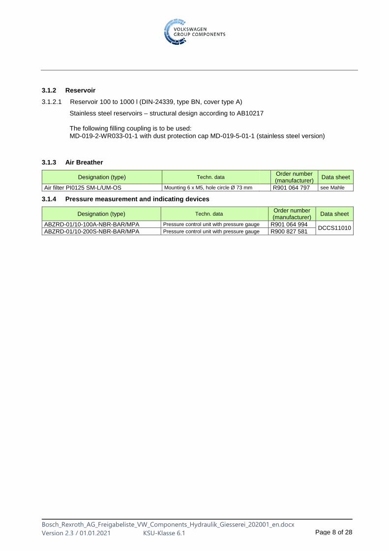
3.1.3 Air Breather
Designation (type) Techn. data Order number (manufacturer)
Data sheet
Air filter PI0125 SM-L/UM-OS Mounting 6 x M5, hole circle Ø 73 mm R901 064 797 see Mahle
3.1.4 Pressure measurement and indicating devices
Designation (type) Techn. data Order number (manufacturer)
Data sheet
ABZRD-01/10-100A-NBR-BAR/MPA Pressure control unit with pressure gauge R901 064 994 DCCS11010
ABZRD-01/10-200S-NBR-BAR/MPA Pressure control unit with pressure gauge R900 827 581
Bosch_Rexroth_AG_Freigabeliste_VW_Components_Hydraulik_Giesserei_202001_en.docx
Version 2.3 / 01.01.2021 KSU-Klasse 6.1 Page 9 of 28
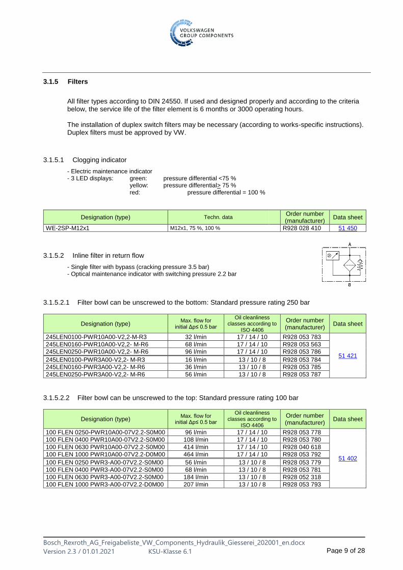
3.1.5 Filters
All filter types according to DIN 24550. If used and designed properly and according to the criteria below, the service life of the filter element is 6 months or 3000 operating hours. The installation of duplex switch filters may be necessary (according to works-specific instructions). Duplex filters must be approved by VW.
3.1.5.1 Clogging indicator
- Electric maintenance indicator - 3 LED displays: green: pressure differential <75 % yellow: pressure differential> 75 % red: pressure differential = 100 %
Designation (type) Techn. data Order number (manufacturer)
Data sheet
WE-2SP-M12x1 M12x1, 75 %, 100 % R928 028 410 51 450
3.1.5.2 Inline filter in return flow
- Single filter with bypass (cracking pressure 3.5 bar) - Optical maintenance indicator with switching pressure 2.2 bar
3.1.5.2.1 Filter bowl can be unscrewed to the bottom: Standard pressure rating 250 bar
Designation (type) Max. flow for
initial Δp≤ 0.5 bar
Oil cleanliness classes according to
ISO 4406
Order number (manufacturer)
Data sheet
245LEN0100-PWR10A00-V2,2-M-R3 32 l/min 17 / 14 / 10 R928 053 783
51 421
245LEN0160-PWR10A00-V2,2- M-R6 68 l/min 17 / 14 / 10 R928 053 563
245LEN0250-PWR10A00-V2,2- M-R6 96 l/min 17 / 14 / 10 R928 053 786
245LEN0100-PWR3A00-V2,2- M-R3 16 l/min 13 / 10 / 8 R928 053 784
245LEN0160-PWR3A00-V2,2- M-R6 36 l/min 13 / 10 / 8 R928 053 785
245LEN0250-PWR3A00-V2,2- M-R6 56 l/min 13 / 10 / 8 R928 053 787
3.1.5.2.2 Filter bowl can be unscrewed to the top: Standard pressure rating 100 bar
Designation (type) Max. flow for
initial Δp≤ 0.5 bar
Oil cleanliness classes according to
ISO 4406
Order number (manufacturer)
Data sheet
100 FLEN 0250-PWR10A00-07V2.2-S0M00 96 l/min 17 / 14 / 10 R928 053 778
51 402
100 FLEN 0400 PWR10A00-07V2.2-S0M00 108 l/min 17 / 14 / 10 R928 053 780
100 FLEN 0630 PWR10A00-07V2.2-S0M00 414 l/min 17 / 14 / 10 R928 040 618
100 FLEN 1000 PWR10A00-07V2.2-D0M00 464 l/min 17 / 14 / 10 R928 053 792
100 FLEN 0250 PWR3-A00-07V2.2-S0M00 56 l/min 13 / 10 / 8 R928 053 779
100 FLEN 0400 PWR3-A00-07V2.2-S0M00 68 l/min 13 / 10 / 8 R928 053 781
100 FLEN 0630 PWR3-A00-07V2.2-S0M00 184 l/min 13 / 10 / 8 R928 052 318
100 FLEN 1000 PWR3-A00-07V2.2-D0M00 207 l/min 13 / 10 / 8 R928 053 793
Bosch_Rexroth_AG_Freigabeliste_VW_Components_Hydraulik_Giesserei_202001_en.docx
Version 2.3 / 01.01.2021 KSU-Klasse 6.1 Page 10 of 28
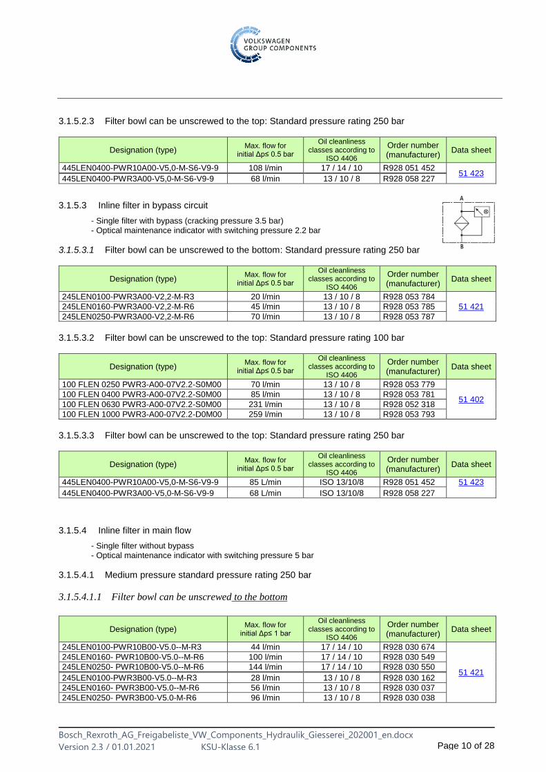
3.1.5.2.3 Filter bowl can be unscrewed to the top: Standard pressure rating 250 bar
Designation (type) Max. flow for
initial Δp≤ 0.5 bar
Oil cleanliness classes according to
ISO 4406
Order number (manufacturer)
Data sheet
445LEN0400-PWR10A00-V5,0-M-S6-V9-9 108 l/min 17 / 14 / 10 R928 051 452 51 423
445LEN0400-PWR3A00-V5,0-M-S6-V9-9 68 l/min 13 / 10 / 8 R928 058 227
3.1.5.3 Inline filter in bypass circuit
- Single filter with bypass (cracking pressure 3.5 bar) - Optical maintenance indicator with switching pressure 2.2 bar
3.1.5.3.1 Filter bowl can be unscrewed to the bottom: Standard pressure rating 250 bar
Designation (type) Max. flow for
initial Δp≤ 0.5 bar
Oil cleanliness classes according to
ISO 4406
Order number (manufacturer)
Data sheet
245LEN0100-PWR3A00-V2,2-M-R3 20 l/min 13 / 10 / 8 R928 053 784
51 421 245LEN0160-PWR3A00-V2,2-M-R6 45 l/min 13 / 10 / 8 R928 053 785
245LEN0250-PWR3A00-V2,2-M-R6 70 l/min 13 / 10 / 8 R928 053 787
3.1.5.3.2 Filter bowl can be unscrewed to the top: Standard pressure rating 100 bar
Designation (type) Max. flow for
initial Δp≤ 0.5 bar
Oil cleanliness classes according to
ISO 4406
Order number (manufacturer)
Data sheet
100 FLEN 0250 PWR3-A00-07V2.2-S0M00 70 l/min 13 / 10 / 8 R928 053 779
51 402 100 FLEN 0400 PWR3-A00-07V2.2-S0M00 85 l/min 13 / 10 / 8 R928 053 781
100 FLEN 0630 PWR3-A00-07V2.2-S0M00 231 l/min 13 / 10 / 8 R928 052 318
100 FLEN 1000 PWR3-A00-07V2.2-D0M00 259 l/min 13 / 10 / 8 R928 053 793
3.1.5.3.3 Filter bowl can be unscrewed to the top: Standard pressure rating 250 bar
Designation (type) Max. flow for
initial Δp≤ 0.5 bar
Oil cleanliness classes according to
ISO 4406
Order number (manufacturer)
Data sheet
445LEN0400-PWR10A00-V5,0-M-S6-V9-9 85 L/min ISO 13/10/8 R928 051 452 51 423
445LEN0400-PWR3A00-V5,0-M-S6-V9-9 68 L/min ISO 13/10/8 R928 058 227
3.1.5.4 Inline filter in main flow
- Single filter without bypass - Optical maintenance indicator with switching pressure 5 bar
3.1.5.4.1 Medium pressure standard pressure rating 250 bar
3.1.5.4.1.1 Filter bowl can be unscrewed to the bottom
Designation (type) Max. flow for
initial Δp≤ 1 bar
Oil cleanliness classes according to
ISO 4406
Order number (manufacturer)
Data sheet
245LEN0100-PWR10B00-V5.0--M-R3 44 l/min 17 / 14 / 10 R928 030 674
51 421
245LEN0160- PWR10B00-V5.0--M-R6 100 l/min 17 / 14 / 10 R928 030 549
245LEN0250- PWR10B00-V5.0--M-R6 144 l/min 17 / 14 / 10 R928 030 550
245LEN0100-PWR3B00-V5.0--M-R3 28 l/min 13 / 10 / 8 R928 030 162
245LEN0160- PWR3B00-V5.0--M-R6 56 l/min 13 / 10 / 8 R928 030 037
245LEN0250- PWR3B00-V5.0-M-R6 96 l/min 13 / 10 / 8 R928 030 038
Bosch_Rexroth_AG_Freigabeliste_VW_Components_Hydraulik_Giesserei_202001_en.docx
Version 2.3 / 01.01.2021 KSU-Klasse 6.1 Page 11 of 28
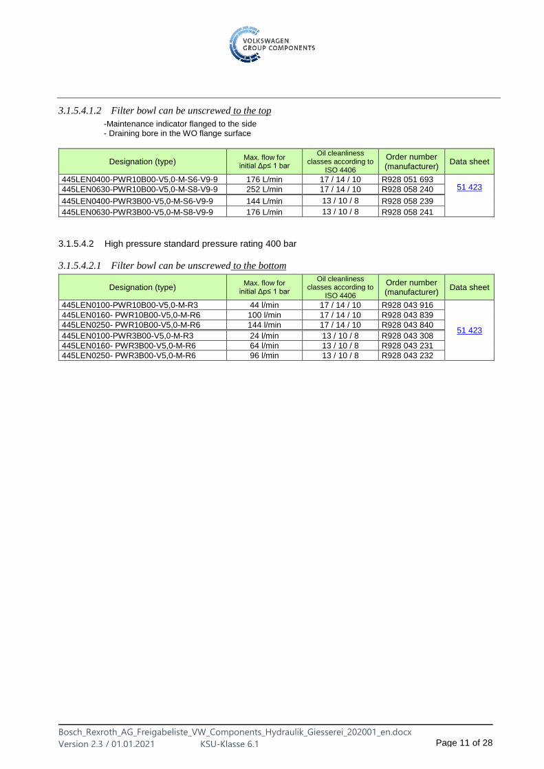
3.1.5.4.1.2 Filter bowl can be unscrewed to the top
-Maintenance indicator flanged to the side - Draining bore in the WO flange surface
Designation (type) Max. flow for
initial Δp≤ 1 bar
Oil cleanliness classes according to
ISO 4406
Order number (manufacturer)
Data sheet
445LEN0400-PWR10B00-V5,0-M-S6-V9-9 176 L/min 17 / 14 / 10 R928 051 693 51 423 445LEN0630-PWR10B00-V5,0-M-S8-V9-9 252 L/min 17 / 14 / 10 R928 058 240
445LEN0400-PWR3B00-V5,0-M-S6-V9-9 144 L/min 13 / 10 / 8 R928 058 239
445LEN0630-PWR3B00-V5,0-M-S8-V9-9 176 L/min 13 / 10 / 8 R928 058 241
3.1.5.4.2 High pressure standard pressure rating 400 bar
3.1.5.4.2.1 Filter bowl can be unscrewed to the bottom
Designation (type) Max. flow for
initial Δp≤ 1 bar
Oil cleanliness classes according to
ISO 4406
Order number (manufacturer)
Data sheet
445LEN0100-PWR10B00-V5,0-M-R3 44 l/min 17 / 14 / 10 R928 043 916
51 423
445LEN0160- PWR10B00-V5,0-M-R6 100 l/min 17 / 14 / 10 R928 043 839
445LEN0250- PWR10B00-V5,0-M-R6 144 l/min 17 / 14 / 10 R928 043 840
445LEN0100-PWR3B00-V5,0-M-R3 24 l/min 13 / 10 / 8 R928 043 308
445LEN0160- PWR3B00-V5,0-M-R6 64 l/min 13 / 10 / 8 R928 043 231
445LEN0250- PWR3B00-V5,0-M-R6 96 l/min 13 / 10 / 8 R928 043 232

Bosch_Rexroth_AG_Freigabeliste_VW_Components_Hydraulik_Giesserei_202001_en.docx
Version 2.3 / 01.01.2021 KSU-Klasse 6.1 Page 12 of 28
3.1.5.5 Replacement elements
For all pressure ratings - Pleated filter elements
3.1.5.5.1 Pressure differential resistance (collapse pressure) 30 bar
Designation (type) Order number (manufacturer)
Data sheet
1.0160 PWR10-A00-0-M ISO 17/14/10 R928 005 891
51 420
1.0250 PWR10-A00-0-M ISO 17/14/10 R928 005 927
1.0400 PWR10-A00-0-M ISO 17/14/10 R928 005 963
1.0630 PWR10-A00-0-M ISO 17/14/10 R928 005 999
1.1000 PWR10-A00-0-M ISO 17/14/10 R928 006 035
2.0100 PWR10-A00-0-M ISO 17/14/10 R928 006 755
2.0160 PWR10-A00-0-M ISO 17/14/10 R928 006 809
2.0250 PWR10-A00-0-M ISO 17/14/10 R928 006 863
2.0400 PWR10-A00-0-M ISO 17/14/10 R928 006 917
2.0630 PWR10-A00-0-M ISO 17/14/10 R928 006 971
1.0160 PWR3-A00-0-M ISO 13/10/8 R928 005 889
1.0250 PWR3-A00-0-M ISO 13/10/8 R928 005 925
1.0400 PWR3A00-0-M ISO 13/10/8 R928 005 961
1.0630 PWR3-A00-0-M ISO 13/10/8 R928 005 997
1.1000 PWR3-A00-0-M ISO 13/10/8 R928 006 033
2.0100 PWR3-A00-0-M ISO 13/10/8 R928 006 753
2.0160 PWR3-A00-0-M ISO 13/10/8 R928 006 807
2.0250 PWR3-A00-0-M ISO 13/10/8 R928 006 861
2.0400 PWR3-A00-0-M ISO 13/10/8 R928 006 915
2.0630 PWR3-A00-0-M ISO 13/10/8 R928 006 969
3.1.5.5.2 Pressure differential resistance (collapse pressure) 330 bar
Designation (type) Order number (manufacturer)
Data sheet
2.0100 PWR10-B00-0-M ISO 17/14/10 R928 006 764
51 420
2.0160 PWR10-B00-0-M ISO 17/14/10 R928 006 818
2.0250 PWR10-B00-0-M ISO 17/14/10 R928 006 872
2.0400 PWR10-B00-0-M ISO 17/14/10 R928 006 926
2.0630 PWR10-B00-0-M ISO 17/14/10 R928 006 980
2.0100 PWR3-B00-0-M ISO 13/10/8 R928 006 762
2.0160 PWR3-B00-0-M ISO 13/10/8 R928 006 816
2.0250 PWR3-B00-0-M ISO 13/10/8 R928 006 870
2.0400 PWR3-B00-0-M ISO 13/10/8 R928 006 924
2.0630 PWR3-B00-0-M ISO 13/10/8 R928 006 978
3.1.6 Oil-water heat exchangers
Designation (type) Techn. dataOrder number (manufacturer)
Data sheet
Heat exchanger TPL00-K-006-22/IG/VE 4 kW (18 l/min); up to 10 bar R900 028 816 DCCS11049-
111
3.1.7 Thermostat
Designation (type) Techn. dataOrder number (manufacturer)
Data sheet
Temperatursensor TR7439 + TT3050 + E35030 2 x normally open/normally closed contacts, programmable
R901 479 122 by IFM
Bosch_Rexroth_AG_Freigabeliste_VW_Components_Hydraulik_Giesserei_202001_en.docx
Version 2.3 / 01.01.2021 KSU-Klasse 6.1 Page 13 of 28
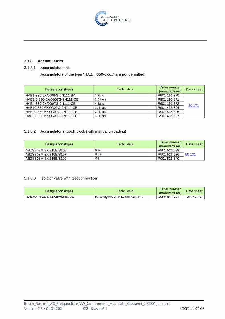
3.1.8 Accumulators
3.1.8.1 Accumulator tank
Accumulators of the type "HAB...-350-6X/..." are not permitted!
Designation (type) Techn. dataOrder number (manufacturer)
Data sheet
HAB1-330-6X/0G05G-2N111-BA 1 liters R901 191 370
50 171
HAB2,5-330-6X/0G07G-2N111-CE 2,5 liters R901 191 371
HAB4-330-6X/0G07G-2N111-CE 4 liters R901 191 372
HAB10-330-6X/0G09G-2N111-CE- 10 liters R901 435 304
HAB20-330-6X/0G09G-2N111-CE- 20 liters R901 435 305
HAB32-330-6X/0G09G-2N111-CE- 32 liters R901 435 307
3.1.8.2 Accumulator shut-off block (with manual unloading)
Designation (type) Techn. dataOrder number (manufacturer)
Data sheet
ABZSS08M-3X/315E/S108 G ¾ R901 526 539
50 131 ABZSS08M-3X/315E/S107 G1 ¼ R901 526 536
ABZSS08M-3X/315E/S109 G2 R901 526 540
3.1.8.3 Isolator valve with test connection
Designation (type) Techn. dataOrder number (manufacturer)
Data sheet
Isolator valve AB42-02/AMR-PA for safety block; up to 400 bar; G1/2 R900 015 297 AB 42-02
Bosch_Rexroth_AG_Freigabeliste_VW_Components_Hydraulik_Giesserei_202001_en.docx
Version 2.3 / 01.01.2021 KSU-Klasse 6.1 Page 14 of 28
3.2 Control devices
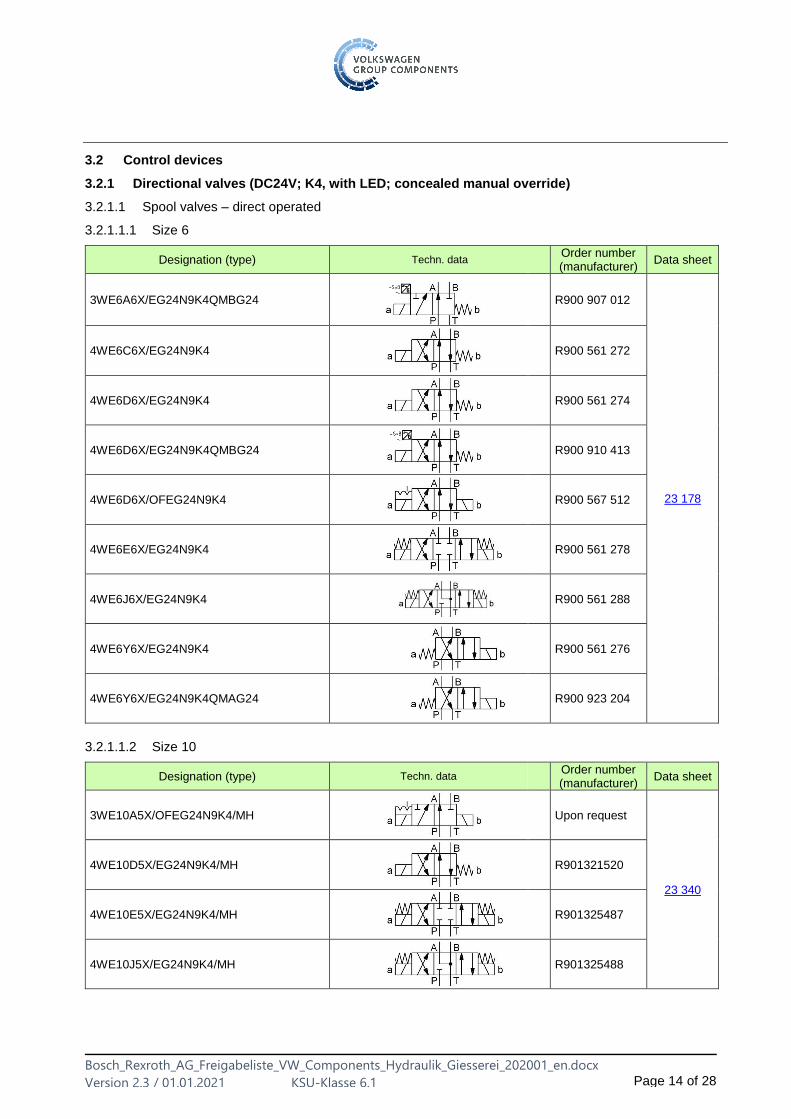
3.2.1 Directional valves (DC24V; K4, with LED; concealed manual override)
3.2.1.1 Spool valves – direct operated
3.2.1.1.1 Size 6
Designation (type) Techn. dataOrder number (manufacturer)
Data sheet
3WE6A6X/EG24N9K4QMBG24
R900 907 012
23 178
4WE6C6X/EG24N9K4
R900 561 272
4WE6D6X/EG24N9K4
R900 561 274
4WE6D6X/EG24N9K4QMBG24
R900 910 413
4WE6D6X/OFEG24N9K4
R900 567 512
4WE6E6X/EG24N9K4
R900 561 278
4WE6J6X/EG24N9K4
R900 561 288
4WE6Y6X/EG24N9K4
R900 561 276
4WE6Y6X/EG24N9K4QMAG24
R900 923 204
3.2.1.1.2 Size 10
Designation (type) Techn. data Order number (manufacturer)
Data sheet
3WE10A5X/OFEG24N9K4/MH
Upon request
23 340
4WE10D5X/EG24N9K4/MH
R901321520
4WE10E5X/EG24N9K4/MH
R901325487
4WE10J5X/EG24N9K4/MH
R901325488
Bosch_Rexroth_AG_Freigabeliste_VW_Components_Hydraulik_Giesserei_202001_en.docx
Version 2.3 / 01.01.2021 KSU-Klasse 6.1 Page 15 of 28
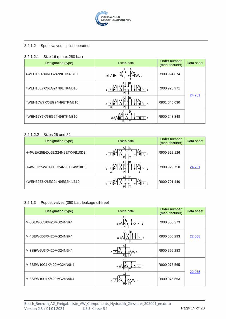
3.2.1.2 Spool valves – pilot operated
3.2.1.2.1 Size 16 (pmax 280 bar)
Designation (type) Techn. dataOrder number (manufacturer)
Data sheet
4WEH16D7X/6EG24N9ETK4/B10
R900 924 874
24 751
4WEH16E7X/6EG24N9ETK4/B10
R900 923 971
4WEH16W7X/6EG24N9ETK4/B10
R901 045 630
4WEH16Y7X/6EG24N9ETK4/B10
R900 248 848
3.2.1.2.2 Sizes 25 and 32
Designation (type) Techn. dataOrder number (manufacturer)
Data sheet
H-4WEH25E6X/6EG24N9ETK4/B10D3
R900 952 126
24 751 H-4WEH25W6X/6EG24N9ETK4/B10D3
R900 929 750
4WEH32E6X/6EG24N9ES2K4/B10
R900 701 440
3.2.1.3 Poppet valves (350 bar, leakage oil-free)
Designation (type) Techn. dataOrder number (manufacturer)
Data sheet
M-3SEW6C3X/420MG24N9K4
R900 566 273
22 058 M-4SEW6D3X/420MG24N9K4
R900 566 293
M-3SEW6U3X/420MG24N9K4
R900 566 283
M-3SEW10C1X/420MG24N9K4
R900 075 565
22 075
M-3SEW10U1X/420MG24N9K4
R900 075 563
Bosch_Rexroth_AG_Freigabeliste_VW_Components_Hydraulik_Giesserei_202001_en.docx
Version 2.3 / 01.01.2021 KSU-Klasse 6.1 Page 16 of 28
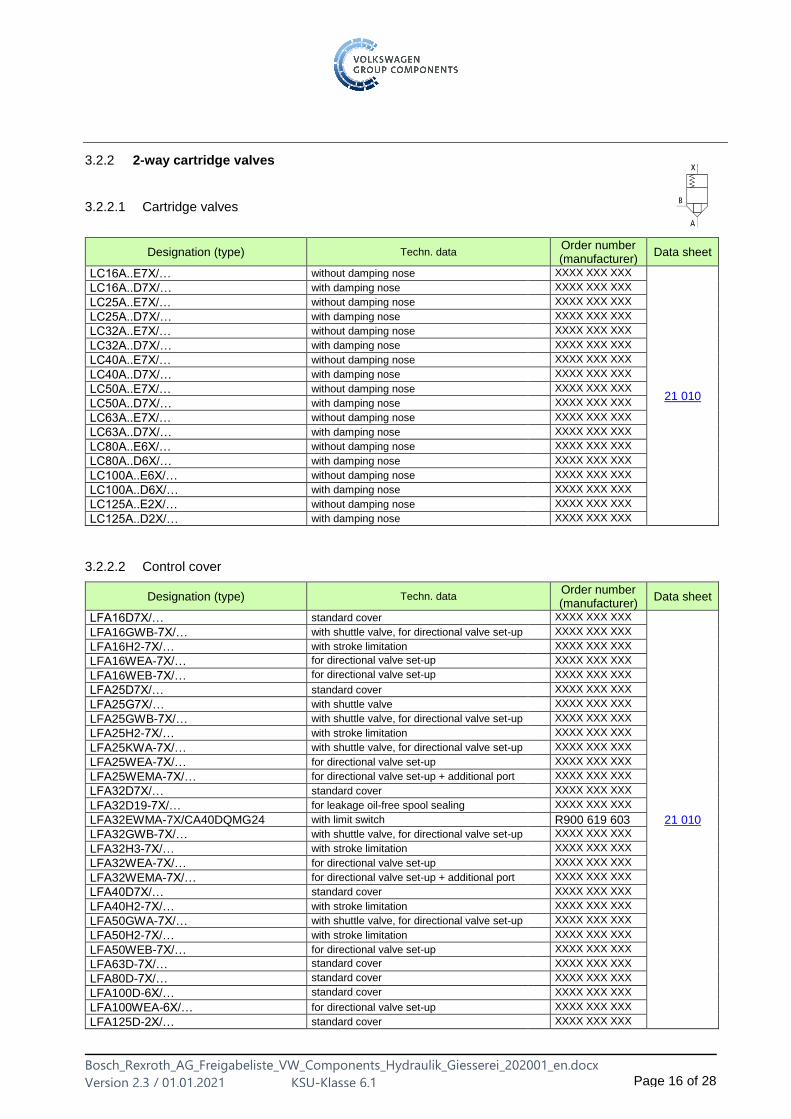
3.2.2 2-way cartridge valves
3.2.2.1 Cartridge valves
Designation (type) Techn. dataOrder number (manufacturer)
Data sheet
LC16A..E7X/… without damping nose XXXX XXX XXX
21 010
LC16A..D7X/… with damping nose XXXX XXX XXX
LC25A..E7X/… without damping nose XXXX XXX XXX
LC25A..D7X/… with damping nose XXXX XXX XXX
LC32A..E7X/… without damping nose XXXX XXX XXX
LC32A..D7X/… with damping nose XXXX XXX XXX
LC40A..E7X/… without damping nose XXXX XXX XXX
LC40A..D7X/… with damping nose XXXX XXX XXX
LC50A..E7X/… without damping nose XXXX XXX XXX
LC50A..D7X/… with damping nose XXXX XXX XXX
LC63A..E7X/… without damping nose XXXX XXX XXX
LC63A..D7X/… with damping nose XXXX XXX XXX
LC80A..E6X/… without damping nose XXXX XXX XXX
LC80A..D6X/… with damping nose XXXX XXX XXX
LC100A..E6X/… without damping nose XXXX XXX XXX
LC100A..D6X/… with damping nose XXXX XXX XXX
LC125A..E2X/… without damping nose XXXX XXX XXX
LC125A..D2X/… with damping nose XXXX XXX XXX
3.2.2.2 Control cover
Designation (type) Techn. dataOrder number (manufacturer)
Data sheet
LFA16D7X/… standard cover XXXX XXX XXX
21 010
LFA16GWB-7X/… with shuttle valve, for directional valve set-up XXXX XXX XXX
LFA16H2-7X/… with stroke limitation XXXX XXX XXX
LFA16WEA-7X/… for directional valve set-up XXXX XXX XXX
LFA16WEB-7X/… for directional valve set-up XXXX XXX XXX
LFA25D7X/… standard cover XXXX XXX XXX
LFA25G7X/… with shuttle valve XXXX XXX XXX
LFA25GWB-7X/… with shuttle valve, for directional valve set-up XXXX XXX XXX
LFA25H2-7X/… with stroke limitation XXXX XXX XXX
LFA25KWA-7X/… with shuttle valve, for directional valve set-up XXXX XXX XXX
LFA25WEA-7X/… for directional valve set-up XXXX XXX XXX
LFA25WEMA-7X/… for directional valve set-up + additional port XXXX XXX XXX
LFA32D7X/… standard cover XXXX XXX XXX
LFA32D19-7X/… for leakage oil-free spool sealing XXXX XXX XXX
LFA32EWMA-7X/CA40DQMG24 with limit switch R900 619 603 LFA32GWB-7X/… with shuttle valve, for directional valve set-up XXXX XXX XXX
LFA32H3-7X/… with stroke limitation XXXX XXX XXX
LFA32WEA-7X/… for directional valve set-up XXXX XXX XXX
LFA32WEMA-7X/… for directional valve set-up + additional port XXXX XXX XXX
LFA40D7X/… standard cover XXXX XXX XXX
LFA40H2-7X/… with stroke limitation XXXX XXX XXX
LFA50GWA-7X/… with shuttle valve, for directional valve set-up XXXX XXX XXX
LFA50H2-7X/… with stroke limitation XXXX XXX XXX
LFA50WEB-7X/… for directional valve set-up XXXX XXX XXX
LFA63D-7X/… standard cover XXXX XXX XXX
LFA80D-7X/… standard cover XXXX XXX XXX
LFA100D-6X/… standard cover XXXX XXX XXX
LFA100WEA-6X/… for directional valve set-up XXXX XXX XXX
LFA125D-2X/… standard cover XXXX XXX XXX
Bosch_Rexroth_AG_Freigabeliste_VW_Components_Hydraulik_Giesserei_202001_en.docx
Version 2.3 / 01.01.2021 KSU-Klasse 6.1 Page 17 of 28
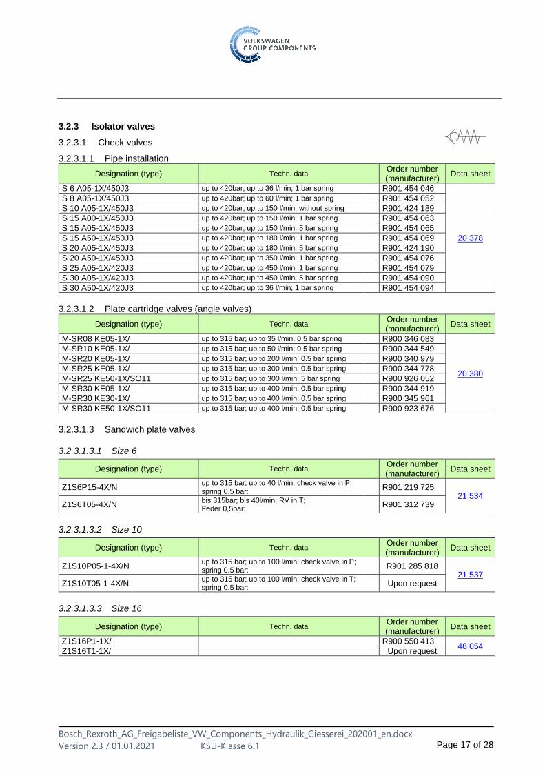
3.2.3 Isolator valves
3.2.3.1 Check valves
3.2.3.1.1 Pipe installation
Designation (type) Techn. dataOrder number (manufacturer)
Data sheet
S 6 A05-1X/450J3 up to 420bar; up to 36 l/min; 1 bar spring R901 454 046
20 378
S 8 A05-1X/450J3 up to 420bar; up to 60 l/min; 1 bar spring R901 454 052
S 10 A05-1X/450J3 up to 420bar; up to 150 l/min; without spring R901 424 189
S 15 A00-1X/450J3 up to 420bar; up to 150 l/min; 1 bar spring R901 454 063
S 15 A05-1X/450J3 up to 420bar; up to 150 l/min; 5 bar spring R901 454 065
S 15 A50-1X/450J3 up to 420bar; up to 180 l/min; 1 bar spring R901 454 069
S 20 A05-1X/450J3 up to 420bar; up to 180 l/min; 5 bar spring R901 424 190
S 20 A50-1X/450J3 up to 420bar; up to 350 l/min; 1 bar spring R901 454 076
S 25 A05-1X/420J3 up to 420bar; up to 450 l/min; 1 bar spring R901 454 079
S 30 A05-1X/420J3 up to 420bar; up to 450 l/min; 5 bar spring R901 454 090
S 30 A50-1X/420J3 up to 420bar; up to 36 l/min; 1 bar spring R901 454 094
3.2.3.1.2 Plate cartridge valves (angle valves)
Designation (type) Techn. dataOrder number (manufacturer)
Data sheet
M-SR08 KE05-1X/ up to 315 bar; up to 35 l/min; 0.5 bar spring R900 346 083
20 380
M-SR10 KE05-1X/ up to 315 bar; up to 50 l/min; 0.5 bar spring R900 344 549
M-SR20 KE05-1X/ up to 315 bar; up to 200 l/min; 0.5 bar spring R900 340 979
M-SR25 KE05-1X/ up to 315 bar; up to 300 l/min; 0.5 bar spring R900 344 778
M-SR25 KE50-1X/SO11 up to 315 bar; up to 300 l/min; 5 bar spring R900 926 052
M-SR30 KE05-1X/ up to 315 bar; up to 400 l/min; 0.5 bar spring R900 344 919
M-SR30 KE30-1X/ up to 315 bar; up to 400 l/min; 0.5 bar spring R900 345 961
M-SR30 KE50-1X/SO11 up to 315 bar; up to 400 l/min; 0.5 bar spring R900 923 676
3.2.3.1.3 Sandwich plate valves
3.2.3.1.3.1 Size 6
Designation (type) Techn. dataOrder number (manufacturer)
Data sheet
Z1S6P15-4X/N up to 315 bar; up to 40 l/min; check valve in P; spring 0.5 bar:
R901 219 725 21 534
Z1S6T05-4X/N bis 315bar; bis 40l/min; RV in T; Feder 0,5bar:
R901 312 739
3.2.3.1.3.2 Size 10
Designation (type) Techn. dataOrder number (manufacturer)
Data sheet
Z1S10P05-1-4X/N up to 315 bar; up to 100 l/min; check valve in P; spring 0.5 bar: R901 285 818
21 537 Z1S10T05-1-4X/N
up to 315 bar; up to 100 l/min; check valve in T; spring 0.5 bar:
Upon request
3.2.3.1.3.3 Size 16
Designation (type) Techn. dataOrder number (manufacturer)
Data sheet
Z1S16P1-1X/ R900 550 413 48 054
Z1S16T1-1X/ Upon request
Bosch_Rexroth_AG_Freigabeliste_VW_Components_Hydraulik_Giesserei_202001_en.docx
Version 2.3 / 01.01.2021 KSU-Klasse 6.1 Page 18 of 28
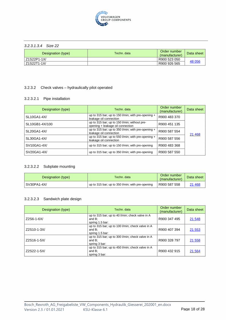
3.2.3.1.3.4 Size 22
Designation (type) Techn. dataOrder number (manufacturer)
Data sheet
Z1S22P1-1X/ R900 523 050 48 056
Z1S22T1-1X/ R900 926 565
3.2.3.2 Check valves – hydraulically pilot operated
3.2.3.2.1 Pipe installation
Designation (type) Techn. dataOrder number (manufacturer)
Data sheet
SL10GA1-4X/ up to 315 bar; up to 150 l/min; with pre-opening + leakage oil connection R900 483 370
21 468
SL10GB1-4X/100 up to 315 bar; up to 150 l/min; without pre-opening + leakage oil connection R900 451 135
SL20GA1-4X/ up to 315 bar; up to 350 l/min; with pre-opening + leakage oil connection R900 587 554
SL30GA1-4X/ up to 315 bar; up to 550 l/min; with pre-opening + leakage oil connection R900 587 556
SV10GA1-4X/ up to 315 bar; up to 150 l/min; with pre-opening R900 483 368
SV20GA1-4X/ up to 315 bar; up to 350 l/min; with pre-opening R900 587 550
3.2.3.2.2 Subplate mounting
Designation (type) Techn. dataOrder number (manufacturer)
Data sheet
SV30PA1-4X/ up to 315 bar; up to 350 l/min; with pre-opening R900 587 558 21 468
3.2.3.2.3 Sandwich plate design
Designation (type) Techn. dataOrder number (manufacturer)
Data sheet
Z2S6-1-6X/ up to 315 bar; up to 40 l/min; check valve in A and B; spring 1.5 bar:
R900 347 495 21 548
Z2S10-1-3X/ up to 315 bar; up to 100 l/min; check valve in A and B; spring 1.5 bar:
R900 407 394 21 553
Z2S16-1-5X/ up to 315 bar; up to 300 l/min; check valve in A and B; spring 3 bar:
R900 328 797 21 558
Z2S22-1-5X/ up to 315 bar; up to 450 l/min; check valve in A and B; spring 3 bar:
R900 432 915 21 564
Bosch_Rexroth_AG_Freigabeliste_VW_Components_Hydraulik_Giesserei_202001_en.docx
Version 2.3 / 01.01.2021 KSU-Klasse 6.1 Page 19 of 28
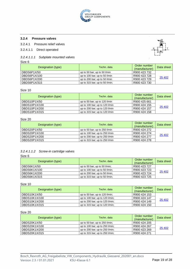
3.2.4 Pressure valves
3.2.4.1 Pressure relief valves
3.2.4.1.1 Direct operated
3.2.4.1.1.1 Subplate mounted valves
Size 6
Designation (type) Techn. dataOrder number (manufacturer)
Data sheet
DBDS6P1X/50 up to 50 bar; up to 50 l/min R900 423 732
25 402 DBDS6P1X/100 up to 100 bar; up to 50 l/min R900 423 728
DBDS6P1X/200 up to 200 bar; up to 50 l/min R900 423 729
DBDS6P1X/315 up to 315 bar; up to 50 l/min; R900 423 730
Size 10
Designation (type) Techn. dataOrder number (manufacturer)
Data sheet
DBDS10P1X/50 up to 50 bar; up to 120 l/min R900 425 661
25 402 DBDS10P1X/100 up to 100 bar; up to 120 l/min R900 424 155
DBDS10P1X/200 up to 200 bar; up to 120 l/min R900 424 157
DBDS10P1X/315 up to 315 bar; up to 120 l/min R900 424 158
Size 20
Designation (type) Techn. dataOrder number (manufacturer)
Data sheet
DBDS20P1X/50 up to 50 bar; up to 250 l/min R900 424 272
25 402 DBDS20P1X/100 up to 100 bar; up to 250 l/min R900 424 274
DBDS20P1X/200 up to 200 bar; up to 250 l/min R900 424 277
DBDS20P1X/315 up to 315 bar; up to 250 l/min R900 424 278
3.2.4.1.1.2 Screw-in cartridge valves
Size 6
Designation (type) Techn. dataOrder number (manufacturer)
Data sheet
DBDS6K1X/50 up to 50 bar; up to 50 l/min; R900 423 727
25 402 DBDS6K1X/100 up to 100 bar; up to 50 l/min; R900 423 723
DBDS6K1X/200 up to 200 bar; up to 50 l/min; R900 423 724
DBDS6K1X/315 up to 315 bar; up to 50 l/min; R900 423 725
Size 10
Designation (type) Techn. dataOrder number (manufacturer)
Data sheet
DBDS10K1X/50 up to 50 bar; up to 120 l/min; R900 424 153
25 402 DBDS10K1X/100 up to 100 bar; up to 120 l/min; R900 424 147
DBDS10K1X/200 up to 200 bar; up to 120 l/min; R900 424 149
DBDS10K1X/315 up to 315 bar; up to 120 l/min; R900 424 150
Size 20
Designation (type) Techn. dataOrder number (manufacturer)
Data sheet
DBDS20K1X/50 up to 50 bar; up to 250 l/min; R900 424 205
25 402 DBDS20K1X/100 up to 100 bar; up to 250 l/min; R900 424 267
DBDS20K1X/200 up to 200 bar; up to 250 l/min; R900 423 269
DBDS20K1X/315 up to 315 bar; up to 250 l/min; R900 424 271
Bosch_Rexroth_AG_Freigabeliste_VW_Components_Hydraulik_Giesserei_202001_en.docx
Version 2.3 / 01.01.2021 KSU-Klasse 6.1 Page 20 of 28
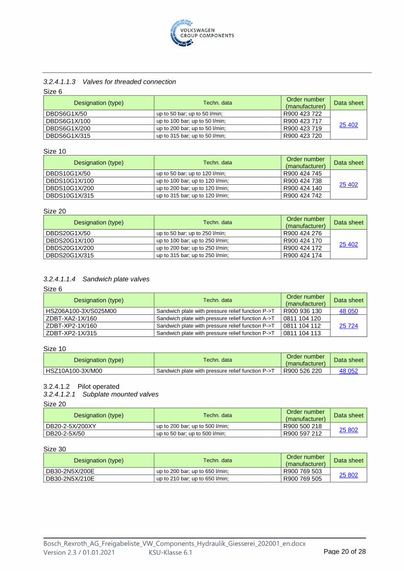
3.2.4.1.1.3 Valves for threaded connection
Size 6
Designation (type) Techn. dataOrder number (manufacturer)
Data sheet
DBDS6G1X/50 up to 50 bar; up to 50 l/min; R900 423 722
25 402 DBDS6G1X/100 up to 100 bar; up to 50 l/min; R900 423 717
DBDS6G1X/200 up to 200 bar; up to 50 l/min; R900 423 719
DBDS6G1X/315 up to 315 bar; up to 50 l/min; R900 423 720
Size 10
Designation (type) Techn. dataOrder number (manufacturer)
Data sheet
DBDS10G1X/50 up to 50 bar; up to 120 l/min; R900 424 745
25 402 DBDS10G1X/100 up to 100 bar; up to 120 l/min; R900 424 738
DBDS10G1X/200 up to 200 bar; up to 120 l/min; R900 424 140
DBDS10G1X/315 up to 315 bar; up to 120 l/min; R900 424 742
Size 20
Designation (type) Techn. dataOrder number (manufacturer)
Data sheet
DBDS20G1X/50 up to 50 bar; up to 250 l/min; R900 424 276
25 402 DBDS20G1X/100 up to 100 bar; up to 250 l/min; R900 424 170
DBDS20G1X/200 up to 200 bar; up to 250 l/min; R900 424 172
DBDS20G1X/315 up to 315 bar; up to 250 l/min; R900 424 174
3.2.4.1.1.4 Sandwich plate valves
Size 6
Designation (type) Techn. dataOrder number (manufacturer)
Data sheet
HSZ06A100-3X/S025M00 Sandwich plate with pressure relief function P->T R900 936 130 48 050
ZDBT-XA2-1X/160 Sandwich plate with pressure relief function A->T 0811 104 120
25 724 ZDBT-XP2-1X/160 Sandwich plate with pressure relief function P->T 0811 104 112
ZDBT-XP2-1X/315 Sandwich plate with pressure relief function P->T 0811 104 113
Size 10
Designation (type) Techn. dataOrder number (manufacturer)
Data sheet
HSZ10A100-3X/M00 Sandwich plate with pressure relief function P->T R900 526 220 48 052
3.2.4.1.2 Pilot operated 3.2.4.1.2.1 Subplate mounted valves
Size 20
Designation (type) Techn. dataOrder number (manufacturer)
Data sheet
DB20-2-5X/200XY up to 200 bar; up to 500 l/min; R900 500 218 25 802
DB20-2-5X/50 up to 50 bar; up to 500 l/min; R900 597 212
Size 30
Designation (type) Techn. dataOrder number (manufacturer)
Data sheet
DB30-2N5X/200E up to 200 bar; up to 650 l/min; R900 769 503 25 802
DB30-2N5X/210E up to 210 bar; up to 650 l/min; R900 769 505

Bosch_Rexroth_AG_Freigabeliste_VW_Components_Hydraulik_Giesserei_202001_en.docx
Version 2.3 / 01.01.2021 KSU-Klasse 6.1 Page 21 of 28
3.2.4.1.2.2 Screw-in cartridge valves
Size 10
Designation (type) Techn. dataOrder number (manufacturer)
Data sheet
DB10K2-4X/50Y up to 50 bar; up to 100 l/min; R900 408 654
25 731 DB10K2-4X/100Y up to 100 bar; up to 100 l/min; R900 430 681
DB10K2-4X/200Y up to 200 bar; up to 100 l/min; R900 481 084
3.2.4.1.2.3 2-way cartridge valves
Cartridge valve
Designation (type) Techn. dataOrder number (manufacturer)
Data sheet
LC16DB20E7X/ R900 912 531
21 050
LC16DB40E7X/ R900 912 532
LC25DB40D7X/ R900 912 555
LC32DB20D7X/ R900 912 556
LC32DB20E7X/ R900 912 543
LC32DB40E7X/ R900 910 773
LC32DB40E7X/004 leakage oil-free R900 919 236
LC32DB50E7X/ R900 947 666
LC402DB20D7X/ R900 928 821
LC40DB20E7X/ R900 938 012
LC40DB40E7X/ R900 927 969
LC40DB40E7X/-104 leakage oil-free R900 947 917
Control cover
Designation (type) Techn. dataOrder number (manufacturer)
Data sheet
LFA16DB2-7X/… pressure limitation XXXX XXX XXX
21 050
LFA16DBWD1-7X/… pressure limitation with shut-off XXXX XXX XXX
LFA32DAWB2-7X/… pressure limitation with shut-off XXXX XXX XXX
LFA32DB2-7X/… pressure limitation XXXX XXX XXX
LFA32DBE-7X/… proportional pressure limitation XXXX XXX XXX
LFA32DBEM-7X/… proportional pressure limitation XXXX XXX XXX
LFA32DBW-7X/… pressure limitation with shut-off XXXX XXX XXX
LFA32DR2-7X/… pressure reduction XXXX XXX XXX
LFA40DB2-7X/… pressure limitation XXXX XXX XXX
LFA40DBW2-7X/… pressure limitation with shut-off XXXX XXX XXX
LFA40DR2-7X/… pressure reduction XXXX XXX XXX
Bosch_Rexroth_AG_Freigabeliste_VW_Components_Hydraulik_Giesserei_202001_en.docx
Version 2.3 / 01.01.2021 KSU-Klasse 6.1 Page 22 of 28
3.2.4.2 Pressure reducing valves
3.2.4.2.1 Direct operated
3.2.4.2.1.1 Subplate mounted valves
Size 6
Designation (type) Techn. dataOrder number (manufacturer)
Data sheet
DR6DP2-5X/150Y up to 150 bar; up to 60 l/min; with check v. R900 413 242 26 564
DR6DP2-5X/210YM up to 210 bar; up to 60 l/min; without check v. R900 455 316
Size 10
Designation (type) Techn. dataOrder number (manufacturer)
Data sheet
DR10DP2-4X/75Y up to 75 bar; up to 80 l/min; with check v. R900 500 471 26 580
DR10DP2-4X/210Y up to 210 bar; up to 80 l/min; with check v. R900 594 125

Bosch_Rexroth_AG_Freigabeliste_VW_Components_Hydraulik_Giesserei_202001_en.docx
Version 2.3 / 01.01.2021 KSU-Klasse 6.1 Page 23 of 28
3.2.4.2.1.2 Sandwich plate valves
Size 6
Designation (type) Techn. dataOrder number (manufacturer)
Data sheet
ZDR6DA2-4X/150YM up to 150 bar; up to 80 l/min; in channel A; without check v. R900 445 958
26 570
ZDR6DA2-4X/150Y up to 150 bar; up to 50 l/min; in channel A; with check v. R900 410 849
ZDR6DA2-4X/210YM up to 210 bar; up to 50 l/min; in channel A; without check v. R900 423 213
ZDR6DA2-4X/210Y up to 210 bar; up to 50 l/min; in channel A; with check v. R900 410 855
ZDR6DB2-4X/150YM up to 150 bar; up to 50 l/min; in channel B; without check v. R900 431 172
ZDR6DB2-4X/210YM up to 210 bar; up to 50 l/min; in channel B; without check v. R900 463 269
ZDR6DP2-4X/150YM up to 150 bar; up to 50 l/min; in channel P; without check v. R900 483 787
ZDR6DP2-4X/210YM up to 210 bar; up to 50 l/min; in channel P; without check v. R900 483 788
Size 10
Designation (type) Techn. dataOrder number (manufacturer)
Data sheet
ZDR10DA2-5X/150YM up to 150 bar; up to 80 l/min; in channel A; without check v. R900 406 225
26 585
ZDR10DA2-5X/150Y up to 150 bar; up to 80 l/min; in channel A; with check v. R900 410 884
ZDR10DA2-5X/210YM up to 210 bar; up to 80 l/min; in channel A; without check v. R900 428 474
ZDR10DA5-5X/210Y up to 210 bar; up to 80 l/min; in channel A; with check v. R900 406 651
ZDR10DB2-5X/150YM up to 150 bar; up to 80 l/min; in channel B; without check v. R900 408 340
ZDR10DB2-5X/210YM up to 210 bar; up to 80 l/min; in channel B; without check v. R900 443 484
ZDR10DP2-5X/150YM up to 150 bar; up to 80 l/min; in channel P; without check v. R900 410 880
ZDR10DP2-5X/210YM up to 210 bar; up to 80 l/min; in channel P; without check v. R900 410 876
3.2.4.2.2 Pilot operated Size 10
Designation (type) Techn. data Order number (manufacturer)
Data sheet
DR10-5-5X/200YM up to 200 bar; up to 150 l/min; without check v. R900 598 358 26 892
Size 20
Designation (type) Techn. data Order number (manufacturer)
Data sheet
DR20-5-5X/200YM up to 200 bar; up to 300 l/min; without check v. R900 597 233 26 892
3.2.4.2.2.1 2-way cartridge valves
Cartridge valve: See chapter 3.2.4.1.2.3 Control cover
Designation (type) Techn. data Order number (manufacturer)
Data sheet
LFA32DR2-7X/… pressure reduction XXXX XXX XXX 21 050
LFA40DR2-7X/… pressure reduction XXXX XXX XXX
Bosch_Rexroth_AG_Freigabeliste_VW_Components_Hydraulik_Giesserei_202001_en.docx
Version 2.3 / 01.01.2021 KSU-Klasse 6.1 Page 24 of 28
3.2.5 Flow control valves
3.2.5.1 Throttle valves
3.2.5.1.1 Pipe fitting
Designation (type) Techn. data Order number (manufacturer)
Data sheet
MG6G1X/ bis 315bar; bis 15l/min; G1/4; R901 349 757
27 219
MG8G1X/ bis 315bar; bis 30l/min; G3/8; R901 400 315
MG10G1X/ bis 315bar; bis 50l/min; G1/2; R901 449 202
MG15G1X/ bis 315bar; bis 125l/min; G3/4; R901 255 443
MG20G1X/ bis 315bar; bis 200l/min; G1; R900 422 149
MG25G1X/ bis 315bar; bis 300l/min; G1 1/4; Bitte anfragen
MG30G1X/ bis 315bar; bis 400l/min; G1 1/2; R901 196 137
3.2.5.2 Throttle check valves
3.2.5.2.1 Pipe fitting
Designation (type) Techn. data Order number (manufacturer)
Data sheet
MK6G1X/ bis 315bar; bis 15l/min; G1/4; R901 353 428
27 219
MK8G1X/ bis 315bar; bis 30l/min; G3/8; R901 226 940
MK10G1X/ bis 315bar; bis 50l/min; G1/2; R900 420 289
MK15G1X/ bis 315bar; bis 125l/min; G3/4; R901 410 695
MK20G1X/ bis 315bar; bis 200l/min; G1; R901 224 660
MK25G1X/ bis 315bar; bis 300l/min; G1 1/4; Bitte anfragen
MK30G1X/ bis 315bar; bis 400l/min; G1 1/2; R901 433 235
3.2.5.2.2 Sandwich plate valves Size 6
Designation (type) Techn. data Order number (manufacturer)
Data sheet
Z2FS6A2-4X/2Q up to 315 bar; up to 80 l/min; in channel A; discharge throttle.
R900 427 254
27 506 Z2FS6B2-4X/2Q up to 315 bar; up to 80 l/min; in channel B; discharge throttle.
R900 423 224
Z2FS6-2-4X/2Q up to 315 bar; up to 80 l/min; in channel A+B R900 481 622
Size 10
Designation (type) Techn. data Order number (manufacturer)
Data sheet
Z2FS10-5-3X/ up to 315 bar; up to 160 l/min; in channel A+B
R900 989 095
27 518 Z2FS10A5-3X/S2 up to 315 bar; up to 160 l/min; in channel A; discharge throttle.
R900 571 890
Z2FS10B5-3X/S2 up to 315 bar; up to 160 l/min; in channel B; discharge throttle.
R900 989 106
Size 16
Designation (type) Techn. data Order number (manufacturer)
Data sheet
Z2FS16A8-3X/S2 up to 350 bar; up to 250 l/min; in channel A R900 348 227 27 526
Z2FS16-3X/S2 up to 350 bar; up to 250 l/min; in channel A+B
R900 457 256
Bosch_Rexroth_AG_Freigabeliste_VW_Components_Hydraulik_Giesserei_202001_en.docx
Version 2.3 / 01.01.2021 KSU-Klasse 6.1 Page 25 of 28
3.2.5.3 Flow control valves
3.2.5.3.1 Subplate mounted valves Size 6
Designation (type) Techn. data Order number (manufacturer)
Data sheet
2FRM6A76-3X/32QR up to 315 bar; up to 32 l/min; with check valve Upon request 28 163
Size 10
Designation (type) Techn. data Order number (manufacturer)
Data sheet
2FRM10-3X/25LB up to 315 bar; up to 25 l/min; R900 423 256 28 389
2FRM10-3X/50LB up to 315 bar; up to 50 l/min; R900 423 261
3.2.5.3.2 Screw-in cartridge valves Size 6
Designation (type) Techn. data Order number (manufacturer)
Data sheet
2FRM6K2-1X/6QR up to 315 bar; up to 6 l/min; R901 249 167 28 155
2FRM6K2-1X/32QR up to 315 bar; up to 32 l/min; R901 254 684
Size 10
Designation (type) Techn. data Order number (manufacturer)
Data sheet
2FRM10K2-1X/60QR up to 315 bar; up to 60 l/min; R901 470 820 28 155

Bosch_Rexroth_AG_Freigabeliste_VW_Components_Hydraulik_Giesserei_202001_en.docx
Version 2.3 / 01.01.2021 KSU-Klasse 6.1 Page 26 of 28
3.3 Proportional and servo valves
Preferably, components with integrated electronics are to be used. If this is not possible, the respective control electronics must be added.
3.3.1 Directional valves
3.3.1.1 Spool valves
Designation (type) Techn. dataOrder number (manufacturer)
Data sheet
4WRKE10…3X/6EG24…K31/…D3M up to 350 bar; with integrated electronics XXXX XXX XXX
29 075 4WRKE16…3X/6EG24…K31/…D3M up to 350 bar; with integrated electronics XXXX XXX XXX
4WRKE25…3X/6EG24…K31/…D3M up to 350 bar; with integrated electronics XXXX XXX XXX
4WRKE35…3X/6EG24…K31/…D3M up to 350 bar; with integrated electronics XXXX XXX XXX
4WRLE16…Z.SJ-3XH/G24:K0/A1M P,A,B up to 350 bar; with integrated electronics XXXX XXX XXX 29 089
4WRPE6…SJ-2X/G24K0.M up to 315 bar; with integrated electronics XXXX XXX XXX 29 025
4WRPE10… SJ-2X/G24K0.M up to 315 bar; with integrated electronics XXXX XXX XXX
4WRVE25…-2XH/G24.K0/B5M P,A,B up to 350 bar; with integrated electronics XXXX XXX XXX 29 077
4WRZ10…-7X/...M up to 350 bar; without integrated electronics XXXX XXX XXX 29 115
3.3.1.2 High-response cartridge valve 2-way and 3-way version
Designation (type) Techn. dataOrder number (manufacturer)
Data sheet
2WRCE32S…-3X/PG24K31/… up to 420 bar, 2-way cartridge valve XXXX XXX XXX
29 137
2WRCE40S…-3X/PG24K31/… up to 420 bar, 2-way cartridge valve XXXX XXX XXX
2WRCE63K…-1X/SG15/M… up to 420 bar, 2-way cartridge valve XXXX XXX XXX
2WRCE80K…-1X/SG15/M… up to 420 bar, 2-way cartridge valve XXXX XXX XXX
2WRCE100K…-1X/SG15/M… up to 420 bar, 2-way cartridge valve XXXX XXX XXX
3WRCE63L…-1X/SG15/M … up to 420 bar, 3-way cartridge valve XXXX XXX XXX
3WRCE80L…-1X/SG15/M… up to 420 bar, 3-way cartridge valve XXXX XXX XXX
3.3.2 Pressure valves: Pressure relief valves
Designation (type) Techn. dataOrder number (manufacturer)
Data sheet
DBET-6X/…G24K4…SO33 up to 420 bar; without integrated electronics Upon request 29 162
DBETE-6X/…G24K31…SO33 up to 420 bar; with integrated electronics Upon request
DBETR-1X/…G24K4M up to 350 bar; without integrated electronics Upon request 29 166
(Z)DBEE6…-2X/…G24NK31M up to 315 bar; with integrated electronics Upon request 29 158
3.3.3 Flow control valves: 2-way proportional throttle valve for block installation
Designation (type) Techn. dataOrder number (manufacturer)
Data sheet
2WFC(E)40S…-1X/..…M up to 315 bar; with integrated electronics XXXX XXX XXX 29 403
Bosch_Rexroth_AG_Freigabeliste_VW_Components_Hydraulik_Giesserei_202001_en.docx
Version 2.3 / 01.01.2021 KSU-Klasse 6.1 Page 27 of 28
3.4 Cylinders
3.4.1 Tie rod cylinders
Piston rod with square, with drain port if required
Designation (type) Techn. data Order number (manufacturer)
Data sheet
CDT3....3X/...H…E…TB… 160 bar; Pistons 25-200 mm; rods 12-140 mm XXXX XXX XXX
17 049 CGT3....3X/...H…E…TB…
160 bar; Pistons 25-200 mm; rods 12-140 mm XXXX XXX XXX
H = Piston rod hardened and hard chromium-plated E = End position cushioning adjustable on both sides B = with leakage oil connection (only for concealed cylinders)
3.5 Accessories
3.5.1 Cover plates
Designation (type) Techn. data Order number (manufacturer)
Data sheet
HSA06A001-3X/M00 up to 315 bar; as cover plate with porting pattern A06
R900 316 232 48 042
Notes: