approved by: mr. fathalla...
TRANSCRIPT

First Semester Report
Fall-2012
-Full Report-
By
Prepared to partially fulfill the requirements for
ECE401: Senior Design I
Department of Electrical and Computer Engineering
Colorado State University
Fort Collins, Colorado 80523
Project Advisor: Dr. George Collins
Graduate Advisor: Mr. Fathalla Eldali
Approved By: _ Mr. Fathalla Eldali _

Pag
e1
Have you ever wondered how it is to live in Dark?! There is one thing that it is known as
a fact, “You cannot lose what you never had”. Do we know what the price of power is? Look
around you, will you find something operating without some kind of power involved? In order
for us to understand how important to live in a place where is no outages, we need to know what
the outages are? How we intend to avoid it? Why does it happened?
Under the supervision of Dr. Collins, our main goal of this semester was to learn and earn
the skills needed to use Siemens software Power System Simulation for Engineering which
called (PSS®E). This program is used to conduct power flow analysis in such way is that we
could design and run simulation on bulk electric system models. This program is available in the
electrical and computer engineering labs. This study will help to achieve our goal and that is
reaching to a better understanding in how power plant works.
Then, we will be able to create a case with necessary multiple files such as *.con,*.mon,
and *.sub and it will include all the information necessary to begin simulation. After that, we will
be evaluating and running some tests to provide a better solution to overcome the overloads. We
planning to create documents that help students to investigate and learn PSS®E for power flow
analysis in power system class.

Pag
e2
I. Introduction ............................................................................................................................. 4
II. Project summary ...................................................................................................................... 6
III. Fall semester accomplishments............................................................................................ 6
Lab 1: Introduction to Power Flow in PSS®E ........................................................................ 6
Lab 2: One-Line Diagrams ...................................................................................................... 8
Lab 3: Solving for Outages ...................................................................................................... 9
Lab 4: AC Contingency Calculation Report .......................................................................... 10
IV. Current work ...................................................................................................................... 11
a. Writing contingency file................................................................................................. 11
b. Writing monitor file ....................................................................................................... 11
c. Writing subsystem file ................................................................................................... 11
V. Conculation and Future Work ............................................................................................... 12
Future Plan ................................................................................................................. 12
Timeline and assignment ........................................................................................... 12
Conclusion ................................................................................................................. 13
Appendix A: List of Abbreviations ........................................................................................... 14
Appendix B: Budget .................................................................................................................. 14
Appendix C: Timelines ............................................................................................................. 15
Appendix D: Lab results and necessities................................................................................... 18
VI. Acknowledgement ............................................................................................................. 20

Pag
e3
Figure 1. sample.sav capture ........................................................................................................... 7
Figure 2. a slider file *.sld .............................................................................................................. 8
Figure 3. outage preformed on the sample.sld ................................................................................ 9
Figure 4. ACCC report .................................................................................................................. 10
Figure 5. a slider file *.sld ............................................................................................................ 18
Figure 6. *.con, *.mon, and *.sub files. ........................................................................................ 19
Pag
e4
This project is meant to develop the stability and brings on better solution and backups
plans for any given power plant. The power simulation system for engineers PSS®E is going to
be our main tool that we will use to serve the goals of this project. Our study will focus on the
power flow and the way it behaves in normal conditions. This study will be applied before we
turn our attention to learn about the behavior of the power flow under any fault or outage.
The study of the power flow analysis using the power simulation system for engineers
will be going through different stations starting by introduction to get more familiarized with the
power simulation system for engineers program and get to know the main element of the power
plant. At first it is necessary to be educated about the power plant and its main elements such as
busses, branches, generators, and transformers. Introducing some of the main terms this report will be focused on we should start with
Power Flow. The user should be able to analyze the performance of power systems in both
normal operating conditions and under fault (short-circuit) condition. The study in normal
steady-state operation is called a power-flow study (load-flow study) and it targets on
determining the voltages, currents, and real and reactive power flows in a system under a given
load conditions. The purpose of power flow studies is to plan ahead and prepare for “system
normal minus one” (N-1) contingences. Power flow studies are fundamental for planning engineers to analyze proposed power
system upgrades. A power flow study also can be used to determine the best and most effective
design of power systems. The PSS/E interface supports a variety of interactive facilities including: • Introduction, modification and deletion of network data using a spreadsheet • Creation of networks and one-line diagrams • Steady-state analyses (load flow, fault analysis, optimal power flow, etc.) • Presentation of steady-state analysis results PSS®E which is focused on power flow, rather than dynamic simulations. PSS®E uses a
graphical user interface that is comprised of all the functionality of state analysis; including load
flow, fault analysis, optimal power flow, equivalency, and switching studies. PSS®E provides the user with a wide range of assisting programs for installation, data input,
output, manipulation and preparation. More importantly, PSS®E allows the user of having a
control over the applications of these computational tools. Buses: this is often in circuit analysis referred to as a node. Busses connect components
(machines, loads, etc.) in the circuit to one another. Branches: they represent transmission lines and they are characterized by impedance.

Pag
e5
Loads: loads are the elements which consume power; loads in AC systems consume real and
reactive power. Machines: they generate power and provide it for the system. 2 Winding Transformer: two to one Transformer Switched Shunts: capacitive or inductive to reduce reactive power in the system This report will be covering five different chapters including this introduction to give our
audience the complete idea of the project with as much details as needed. After this introduction chapter there comes the project summery this project is to deliver
our purpose and goals and what can be said about the project in few words. The next chapter is
the
Fall semester accomplishment where there is what progress has the team done during the
fall semester of the project. Next chapter is about what is the team currently working on with
more explanation about that. Finally we sum up with conclusion that contains what the team has
earned from this semester and what are goals have been accomplished and what is the plan for
the spring semester with the targets that the team will be working to achieve.

Pag
e6
We chose the project to be our senior design project because of our interests in Power
field in our future career. These interests led us to work with Dr. Collins to research in power
area using software called Power System Simulation for Engineering (PSS®E). In order for us to
be introduce to the PSS®E, Dr. Collins suggested that we work on the lab manuals for his class
Power Systems. We completed working the labs until lab 5 which did not work as it’s supposed
to be due to the structure of the lab built on old version of PSS®E that is different of what the
CSU computers lab have ( version 32.0.3) . As we went through the labs, we gained a better
understanding of the software and we started to rearrange lab 5 titled “Multiple ACCC Report”.
We plan to finish editing this lab before January 1st of 2013 to work correctly.
For this semester, our goal is to get familiar with PSS®E software and master the basic tools
to propose studies using the program to upgrades power system on Bonanza TOT1A. These labs
introduce the fundamental of power flow analysis. We accomplished the following labs learning
and revising:
Introduction to Power Flow in PSS®E
The purpose of this lab is to get to know important components used to analyze the power
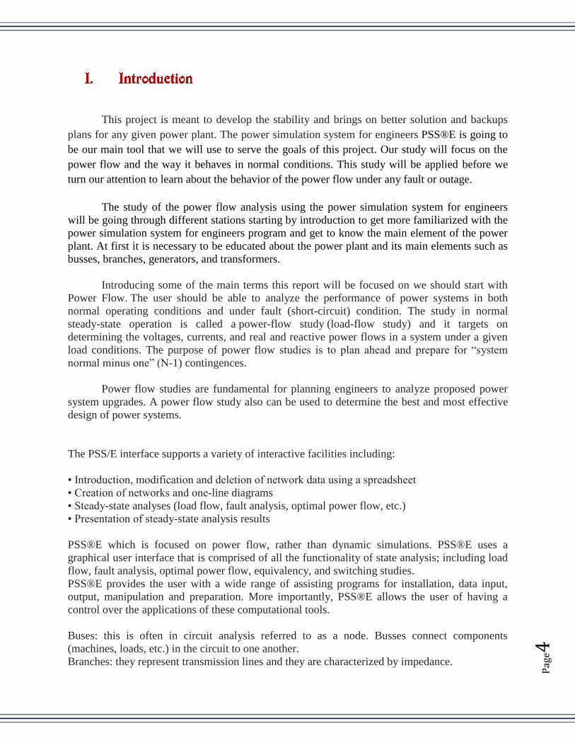
flow study. This lab introduce the save file *.sav which is a binary image of the load power flow
working case. The file specified to 19 tabs of all the components and functions in the system.
Through the lab we focused on six tabs and they are:
Bus: includes the buses name, number, voltage in kV, code, etc.
Branch: shows transmission lines and data record of the system.
Load: shows the elements that consume power both real and reactive power.
Machine: generate power and apply it to the system.
2 Winding Transformer: shows the data records block of the system.
Switched shunt: it shows the capacitive or inductive that reduces the reactive power in the
system.
Pag
e7
The save file is storage of all the data of any power system that need to analyze for configure the
power flow behavior Figure 1.
Figure 1. Sample.sav capture

Pag
e8
One-Line Diagrams
In the second the lab, we started to know an important file called slider file *.sld which is
a one-line diagram represent of three phases power system. These phases are balanced in power
engineering therefore, they can be examine as single phase. Slider file is a grid as in Figure 2
where it shows the power system on sample case that we are using in these labs. slider file is
linked to the save file where it shows all the data records so any changes in either file will
change in the other one. We learn a lot by doing this lab and allow us to think of creating a slider
file if we have save file handy. All the components shown are color coded based on voltage flow.
One more thing we learned after creating or editing the slider file is that we solve the system
using the PSS®E to create all necessary calculations in a power flow analysis. The result grid
shown in Figure 2, shows the percentage of the loads in the branches and what needs to looking
for to overcome any overloads. Overloads appear in dark red color that is over 100% of it is rated
capacity. Also, we followed the direction of the power flow during the analysis.
Figure 2. A slider file *.sld

Pag
e9
Solving for Outages
In lab 3, the purpose is to learn how to solve for outages in power system. Using the
slider file created in lab 2, we created fault outages and then solve these outages. The benefit of
creating an outage is to learn how the power flow performance changes through the system.
After solving the system in lab 2, we took a bus or other elements out of service and investigate
its impact to the system. The transmission line that connected to equipment where it’s out of
service are changed into dotted lines and the grid is grayed out. Dotted lines mean the items are
not in service anymore and the system has to be solved again. Figure 3.
Figure 3. Outage preformed on the sample.sld
Pag
e10
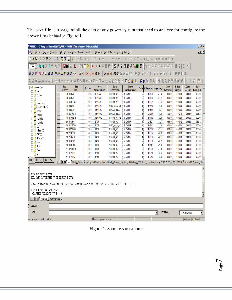
AC Contingency Calculation Report
ACCC; AC Contingency Calculation report is a result of a power flow study on a specific
zone. In order to interpret an ACCC report we have to write three important files which are
Contingency file *.con, Monitor file *.mon, and Subsystem file *.sub. these files set up to
overcome any necessary overloads that needs to be taking care of. In lab 3, we did this manually
but here using ACCC method will take care of that automatically. Below is a portion of ACCC
report taking from the lab manual that shows the monitor branches and the name of the
contingency with loads. Figure 4.
Figure 4. ACCC report

Pag
e11
We conducted to work in fixing lab 5 multiple ACCC report. We need to design the lab so
that the user (student of Power System class) will have an easy access to complete the lab in the
PSS®E 32 version without any problems. On the sample case that we are working on, the grid
has 9 zones and each zone will need a contingency, monitor, and subsystem files to run ACCC
report. The files are shown below:
a- Writing contingency file *.con: it’s the way to trip equipment, once at a time from
service. When system has no outages is called system intact N-0 and when a single line is
taken out of service, it’s referred to N-1. Below is portion of the code from the lab 5
manual:
COM
COM Contingency Description File for zone# Study, Outages
COM
TRACE
CONTINGENCY NUC-MD5
TRIP LINE FROM BUS 151 TO BUS 152
END
b- Writing monitor file *.mon: this file will choose branches to be supervised during N-1
contingency by the power flow software for prescribed zone. Below is portion of the code
from the lab 5 manual:
COM
COM Monitored Element Description File for zone# Study, Outage
COM
MONITOR BRANCHES IN SUBSYSTEM OVERAL
MONITOR VOLTAGE RANGE SUBSYSTEM OVERAL 0.90 1.10
MONITOR VOLTAGE DEVIATION SUBSYSTEM OVERAL 0.5 0.5
MONITOR INTERFACE ZONE6H RATING 500 MW
152 3004
3002 3004
END
END
c- Writing subsystem file *.sub: this file direct power flow analysis to only look at a
specific zone of the network. Below is portion of the code from the lab 5 manual:
COM
COM System description file for zone# FLOW STUDY
COM
SUBSYSTEM OVERAL

Pag
e12
BUS 101
BUS 102
BUS 151
BUS 152
BUS 153
BUS 154
BUS 155
END
END
Future Plan:
During the spring semester the team will have another sample case of the power
simulation system for engineers to work with. We will need to apply everything we learned
during Fall semester in this project. Since the older sample file is no longer valid to use by
student the team will help creating new lab manuals that apply to the new case to make it easy
for other students to learn about PSS®E. then, a study for the system when it is under fault will
be applied to find contingency plans (solutions), then test them and see if they are the appropriate
and if they can overcome the overloads and outages effects on the system.
Timeline and Assignments:
During the January of 2013 our team is expected to be done with creating the first lab
which is an introduction to power flow analyzing. In February the team will be covering creating
and modifying the .con, .sub, .mon files and do the configurations and apply the contingency
analyzes. A second lab manual for the creating and modifying will be created after we finish the
study.
In March the team is expected to have the study of the analyzes overloads which will be
creating, adding and simulate solutions to the under fault given system. A lab manual will be
created to teach about the testing the system for overloads.
In April, the team is expected to be done with the reanalyzing and evaluate the found
contingency plans.

Pag
e13
Job to do Khamal Meshari date
Research for the first
lab of the new sample
case
Working together 1/21/13 - 2/4/13
Outlines and main
points
2/4/13 - 2/18/13
Create the lab and do
the writing
Writing the lab Check and ask the
adviser questions if
needed
2/18/13 - 2/25/13
Test the lab and make
sure of no mistakes
Working together then meeting the adviser for
last changes
2/25/13 - 3/4/13
covering creating and
modifying the .con,
.sub, .mon files for the
new case and do the
configurations and
apply contingency
Working together 3/4/13 - 3/18/13
Creating a 2nd
lab
about con, .sub, .mon
files
Study, research and outline 3/18/13 - 3/25/13
Creating a 2nd lab
about con, .sub, .mon
files
Review and make sure
of no mistakes
Writing the lab 03/25/13 - 4/1/13
study of the analyzes
overloads which will
be creating, adding and
simulate solutions to
the under fault given
system
Working together 04/1/13 - 04/08/13
A lab manual will be
created to teach about
the testing the system
for overloads.
Research and outline 04/08/13 - 04/15/13
Writing the lab Review and make sure
of no mistake
04/15/13 – 04/22/13
reanalyzing and
evaluate the found
contingency plans.
Working together 0/4/22/13 - 04/3013
Conclusion:
This project is meant to benefit the industry of power generation with studies of the
overcoming the system when is under fault or outage on a smaller fake case that will help us as
student to get trained and be very familiar with power plants. Power simulation system for
engineers PSS®E is the software that we used to serve our purposes. Also new lab manual for
students of the power systems class will be created to make sure they have the best knowledge of
the PSS®E in the easiest way.
Pag
e14
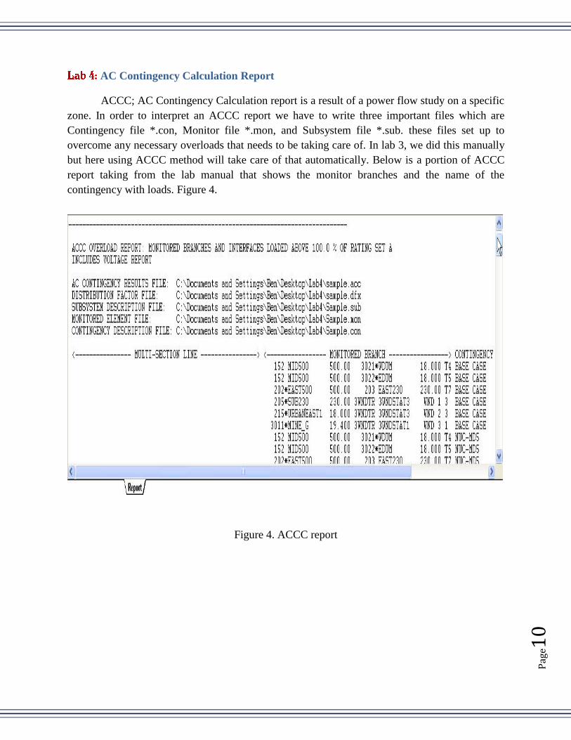
Appendix A: List of Abbreviations
PSS®E : Power System Simulation for Engineering
ACCC : AC Contingency Calculation
N-1 : Contingency
E-Day : Engineering Day
Appendix B: Budget
As of right now, our project budget is very limited because we will be researching and
completing lab and creating lab manual using PSS®E program which is provided on the lab
computers by Colorado State University. This program is what we basically all need. We might
need to spend some money on E- Day supplies for a couple poster boards, some double-sided
tape, and to print out large posters on a plotter.

Pag
e15
Appendix C: Timelines
Friday, August 31, 2012
Task Week #
Meshari’s project plan. Khamal’s project plan.
I worked in set up the equipment and
timeline the project.
Review the PSS®E labs Week 1
As of this week, I will start working in
PSS®E labs first, introduction to PSS®E
how to use it and get familiar with.
Second, working on One-line diagrams
which is simplified graphical
representation of a three phase power
system, used extensively in power flow
studies.
Rewrite lab 1,2 Week 2
Working in Solving for outages in the
power system by creating, solving, and
recording the effect of individual
outages.
Rewrite lab 3 Week 3
Create AC contingency Calculation
report and get an understanding of
ACCC feature of PSS®E to perform a
power flow study on a particular zone.
Rewrite lab 4 Week 4
Multiple ACCC report. Rewrite lab 5 Week 5
Multiple ACCC report. Cont.. Rewrite lab 6 Week 6
Load Shedding by developing and
analyzing load shedding strategies
based on a simplified model for a small
city. Develop power systems from
scratch.
Check all labs and make sure
no mistakes were made.
Week 7
From week 8 till week 15, we intend to build a new lab titled “Addition
of Generation” demo to be presented next year for the student using
PSS®E. this lab will be in a wind farm as a base case and analyze the
effects using PSS®E.
Week 8-15
Pag
e16
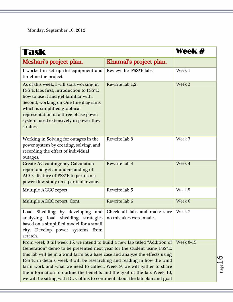
Monday, September 10, 2012
Task Week #
Meshari’s project plan. Khamal’s project plan.
I worked in set up the equipment and
timeline the project.
Review the PSS®E labs Week 1
As of this week, I will start working in
PSS®E labs first, introduction to PSS®E
how to use it and get familiar with.
Second, working on One-line diagrams
which is simplified graphical
representation of a three phase power
system, used extensively in power flow
studies.
Rewrite lab 1,2 Week 2
Working in Solving for outages in the
power system by creating, solving, and
recording the effect of individual
outages.
Rewrite lab 3 Week 3
Create AC contingency Calculation
report and get an understanding of
ACCC feature of PSS®E to perform a
power flow study on a particular zone.
Rewrite lab 4 Week 4
Multiple ACCC report. Rewrite lab 5 Week 5
Multiple ACCC report. Cont. Rewrite lab 6 Week 6
Load Shedding by developing and
analyzing load shedding strategies
based on a simplified model for a small
city. Develop power systems from
scratch.
Check all labs and make sure
no mistakes were made.
Week 7
From week 8 till week 15, we intend to build a new lab titled “Addition of
Generation” demo to be presented next year for the student using PSS®E.
this lab will be in a wind farm as a base case and analyze the effects using
PSS®E. in details, week 8 will be researching and reading in how the wind
farm work and what we need to collect. Week 9, we will gather to share
the information to outline the benefits and the goal of the lab. Week 10,
we will be sitting with Dr. Collins to comment about the lab plan and goal
Week 8-15

Pag
e17
Friday, October 19, 2012
Task Date
Meshari’s project plan. Khamal’s project plan.
I worked in set up the equipment and
timeline the project.
Review the PSS®E labs 8/20/12
As of this week, I will start working in
PSS®E labs first, introduction to PSS®E
how to use it and get familiar with.
Second, working on One-line diagrams
which is simplified graphical
representation of a three phase power
system, used extensively in power flow
studies.
Rewrite lab 1,2 8/27/12
Working in Solving for outages in the
power system by creating, solving, and
recording the effect of individual
outages.
Rewrite lab 3 9/3/12
Create AC contingency Calculation
report and get an understanding of
ACCC feature of PSS®E to perform a
power flow study on a particular zone.
Rewrite lab 4 9/10/12
Multiple ACCC report. Rewrite lab 5 10/1/12
Creating Multiple files for different
Zones in the Sample file.
Rewrite lab 5 11/15/12
Testing *.Con, *.Mon, and *.Sub Files in PSS®E 12/2/12
and revise. Week 11-14, start working in the lab and create the format and
redo it multiple times to insure we cover all the possible errors that may
occur during the lab steps.

Pag
e18
Appendix D: Lab results and necessities
Figure 5. A slider file *.sld, we created in Lab 2 that shows how our learning skills improved in
establishing a slider file for a system

Pag
e19
Figure 6. We created the three files needed to create ACCC report for zone 2 as a sample will be
published in lab 5 manual.

Pag
e20
Special thanks are due to Prof. George Collins, Senior Project supervisor of the Project
Bonanza Effects on TOT1A, who gave us the chance to be part of this team to learn and have
this phenomenal experience which hopefully will give us a little taste of the power industry.
Mr. Fathalla Eldali, who being around when we needed him planning and answering
questions regarding power in general. Also, thanks to him for his contributions regarding using
the PSS®E program.
Mr. Joe Liberatore, our industry advisor for his contributions in planning our goals for
next semester. We will need his professional skills in learning PSS®E.