approach to the weight estimation in the conceptual design
TRANSCRIPT

Research ArticleApproach to the Weight Estimation in the Conceptual Design ofHybrid-Electric-Powered Unconventional Regional Aircraft
Francesco Centracchio Monica Rossetti and Umberto Iemma
Roma Tre University Department of Engineering Rome Italy
Correspondence should be addressed to Francesco Centracchio francescocentracchiouniroma3it
Received 15 June 2018 Accepted 27 September 2018 Published 17 October 2018
Guest Editor Vladislav Zitricky
Copyright copy 2018 Francesco Centracchio et al This is an open access article distributed under the Creative Commons AttributionLicense which permits unrestricted use distribution and reproduction in any medium provided the original work is properlycited
The present work deals with the development of an innovative approach to the weight estimation in the conceptual design of aHybrid-Electric-Powered (HEP) Blended Wing Body (BWB) commercial aircraft In the last few decades the improvement ofthe environmental impact of civil aviation has been the major concern of the aeronautical engineering community in order toguarantee the sustainable development of the system in presence of a constantly growing market demand The sustained effort inthe improvement of the overall efficiency of conventional aircraft has produced a new generation of vehicles with an extremely lowlevel of emissions and noise capable of covering the community requirements in the short term Unfortunately the remarkableimprovements achieved represent the asymptotic limit reachable through the incremental enhancement of existing conceptsAny further improvement to conform to the strict future environmental target will be possible only through the introduction ofbreakthrough concepts The aeronautical engineering community is thus concentrating the research on unconventional airframesinnovative low-noise technologies and alternative propulsion systems The BWB is one of the most promising layouts in termsof noise emissions and chemical pollution The further reduction of fuel consumption that can be achieved with gaselectrichybridisation of the power-plant is herein addressed in the context of multidisciplinary analyses In particular the payload andrange limits are assessed in relation to the technological development of the electric components of the propulsion system Thepresent work explores the potentialities of an energy-based approach for the initial sizing of a HEP unconventional aircraft in theearly conceptual phase of the design A detailed parametric analysis has been carried out to emphasise how payload range anddegree of hybridisation are strictly connected in terms of feasible mission requirements and related to the reasonable expectationsof development of electric components suitable for aeronautical applications
1 Introduction
For many decades aeronautics and air transport have beenan essential component of our global society for all countriesthis industry has a substantial impact on the global economicsocial and cultural development The civil aviation systemcurrently involves about 29 million employees worldwidethrough direct indirect and induced activities and ensuresthe transfer of passengers and goods fromto themost remoteareas of the planet in a constantly decreasing time As matterof fact the aviation industry has constantly grown through-out the last century and is expected to further increase inthe near future The average annual rate of 44 in termsof transport capacity (revenue passenger kilometres RPK)
experienced over the period 1989-2009 [1] is foreseen togrow to more than 5 in the 2030 horizon [2] This growth(see Figure 1) is mostly due to the progressive access to thecivil aviation system of the emerging economies (such asAsia Middle-East Africa and Latin America) with morethan 6 RPK annual increment during the last decades [23]
Although aviation currently accounts for only 2-3 (seeFigure 2) of the 36 billion metric tons of 1198621198742 emissions ofanthropic origin [4] these emissions are projected to grow inthe foreseeable future as the air traffic increases a 75 1198621198742
increment was recorded between 1990 and 2012 and it isforeseen to grow 300 by 2050 unless preventive action istaken [5]
HindawiJournal of Advanced TransportationVolume 2018 Article ID 6320197 15 pageshttpsdoiorg10115520186320197
2 Journal of Advanced Transportation
0500
10001500200025003000350040004500
RPK
1995Change 1995-2010
Asia
Pac
ific
Asia
Pac
ific
Euro
pe
Euro
pe
Nor
th A
mer
ica
Nor
th A
mer
ica
Mid
dle E
ast
Mid
dle E
ast
Latin
Am
Car
ib
Latin
Am
Car
ib
Afr
ica
Afr
ica
012345678910
RPK
Gro
wth
[]
Change 2010-2030Growth Rate 2010-2030
Figure 1 ICAO passenger traffic forecast by ICAO statistical region [9]
Agriculture14
Waste and Wastewater
3
Energy supply26 Industry
19
Forestry17
Transport13
Residential and Commercial Buildings
8
Global GHG by Section2004 (IPCC)
Aviation CO2
emissions 2
Global CO2 emissions
98
Part of AviationGlobal CO2 Emissions
Aviation 13
Other 13
Road 74
Global CO2 emissionsper transport ()
Figure 2 Aviation contribution to global 1198621198742 emissions [9]
However carbon dioxide emissions are not the onlycontribution to the global warming of the aeronauti-cal transportation system Also the water vapour cloudformation ozone generation methane reduction partic-ulates carbon monoxide unburnt hydrocarbons sootoxides of sulphur and nitrogen oxides should be consid-ered [6] For sake of clarity 1198621198742 and water vapour are
grouped under the label GreenndashHousendashGas (GHG) emis-sions responsible for the temperature of Earthrsquos surfaceincrease As 90 of 1198621198742 emissions from global commer-cial aircraft are associated with vehicles carrying morethan 100 passengers (twin-aisle and single-aisle aircraft)research should focus on developing innovative technolo-gies to reduce emissions for large aircraft [7] Most likely
Journal of Advanced Transportation 3
these solutions will be then suitable for smaller aircraft aswell
With regard to Paris Climate Change Conference(COP21) in 2015 where it was established to keep the globaltemperature rise below 2∘C compared to preindustrial levels[8] the contribution of air transport to global warming inthe near future can no longer be ignored [6]
For these reasons since the 90s the international institu-tions involved have formulated quantitative goals for limitingGlobal GHG emissions establishing common targets to befulfilled by the future aviation 1198621198742 emissions per RPKreduction of 60 by 2035 and 75 by 2050 with regard toreference year 2000119873119874119909 emissions reduction of 84by 2035and 90 by 2050 with regard to year 2000
The International Civil Aviation Organisation (ICAO)has developed since 2010 a number of measures whichinclude technological standards alternative fuels operationaland market-based measures aiming at promoting standardsand regulations for aviation safety security efficiency capac-ity and environmental protection [9] In order to con-cur with all the partner countries on the development ofcommon trading schemes and policies for carbon neutralgrowth ICAO established the Global Market-Based Measure(GMBM) in 2016 as an international agreement to tacklegrowth in carbon dioxide emissions of aviation industry from2020 onwards [4 6] This action supports the 2035 globalaviation industry as carbon neutral growth ambition andseems to be a promising mean to achieve the halving of 1198621198742
emissions by 2050 [12] Among others ICAO has establishedthe Committee on Aviation and Environmental Protection(CAEP) to formulate new 1198621198742 Standard to be applied toaircraft of the next generation [4] However to satisfy theselong termgoals not only is effort from industries sufficient butalso contribution fromGovernment Institutions is necessaryon both Research and Development (RampD) and policy bymeans of respectively subsidises and new regulation for AirTraffic Management (ATM) [12]
Beside the environmental considerations presented thereare other motivations inducing an increasing interest in HEPaircraft The airline companies are economically interested inreducing fuel burnt per flight due to the typical fluctuation offuel price and its uncertain trend as fossil-fuel reserves willrun short [7] (historical trend provided by Federal ReserveBank of St Louis is reported in Figure 3 for the period012002ndash062018)
As it can be appreciated in Figure 4 IATA has reportedin its Press-room Fact Sheets [13] that global commercialairline industryrsquos fuel bill has been estimated to be 21of totaloperating expenses in 2017 and it is foreseen to be around 24in 2018
As a short-term alternative to standard fuel SustainableAlternative Jet Fuels (SAJF) are strongly appealing themarket[7 14] Potential alternatives that have been intensely studiedinclude hydrogen blending of ethanol and bio-diesel withconventional jet fuel nuclear power and compressed orliquefied natural gas Ploetner et al in [15] reported a compar-ison between possible scenarios for emissions reduction bymeans of new aircraftfleet and procedures in 2050 All studiesconsidered in the paper have shown that available aircraft
0000050010001500200025003000350040004500
Dol
lars
per
Gal
lon
Figure 3 Kerosene-type jet fuel prices in US Gulf Coast [10]
-113 -75-56
-41
5
147
-261
-46
17383 92 107 138
36 34238
338
minus10
40
90
140
190
240
minus30minus20minus10
01020304050
2002 2003 2004 2005 2006 2007 2008 2009 2010 2011 2012 2013 2014 2015 2016 2017 2018F
Net Profits ($ Billion)
Total Industry Fuel Costs ($ billion)
Figure 4 Industry fuel costs and net profits trends in aviation [11]
technology improvements are not sufficient to achieve thestrict targets imposed by institutions for 2035 while air trafficgrows In a long-term scenario (2050) if novel configurationsradical technologies on aircraft level alternative fuels andramp-up timelines in aircraft production are consideredGHG global emissions can be limited to 15 to 35 comparedto 2005 baseline when air traffic growth is accounted
Although dual energy sources and novel high-efficiencyconfigurations are key aspects to accomplish the demandingrequest of emissions abatement the current state of the art inspecific power of each electric component and specific energy119867119887 of todayrsquos batteries (as well as low energy density 984858119887) is stillfar from being effective for aeronautical applications All thepapers dealing with the issue of hybrid aircraft state that akey role is given to the efficiency of the elements that con-stitute the power-plant which makes electric hybridisationappealing for the reduction of GHG emissions in aviationIt is worth noting that despite the high gravimetric energyof fuel 119867119891 and the related energy density 984858119891 the efficiencyassociated with conventional engine chain 120578119905ℎ119888ℎ is rather low incomparison with electrical chain 120578119890119897119888ℎ
Conv
120578119905ℎ119888ℎ ≃ 03119867119891 = 128 119896119882ℎ119896119892984858119891 = 104 119896119882ℎ119897
4 Journal of Advanced Transportation
Elect
120578119890119897119888ℎ ≃ 085119867119887 = 026 119896119882ℎ119896119892984858119887 = 069 119896119882ℎ119897
(1)
Although the technological development of electricengines controllers generators inverters batteries etc is notadvanced enough for aeronautical applications it is necessaryto identify which specific power specific energy and energydensity are required to have an advantage in this field
The reason why hybridisation is nowadays not yet feasiblefor commercial aircraft while it can be considered as wellestablished for ground vehicles is the substantial weightand volumetric penalty of the electric components causedby the high level of energy and power required Indeed allalternative energy sources have a volumetric energy densitymuch lower than kerosene and consequently weight volumeand drag penalties must be taken into account to quantifythe possible advantage of substituting traditional fuel [7]Today the fuel is stored in the wings of aircraft in order toaccomplish few specific requirements (i) it surrounds thecentre of gravity to keep its position constant while fuel isburnt (ii) its weight counter-balance the bending momentdue to the lift force (iii) it does not affect the volume forpayload Another important aspect is the weight reductiona conventional aircraft is subjected to during the missionas fuel is burnt The amount of lost weight depends on thescheduled range and it is of course more significant for long-haul mission This implies that the actual energy requiredfor a fuel-powered aircraft would definitely be less than theenergy required for the same mission of a batteryndashpoweredaircraft As reported in [16] the minimum gravimetric energyof batteries required in aeronautics is about 500 kWhkgand even so the energy storage density will be 25 timeslower than jet fuel corresponding to a high volume demandand additional weight Moreover safety is also an importantaspect to be considered all standards must be reviewed andchanged in order to account for novel propulsion systems andenergy storing
Beside technical considerations it is also mandatory toanalyse whether these technologies would be costly effectivefor the demand market [17] An envisioned starting pointfor electrification of aircraft is the application for Urban AirTaxis or regional segment [16] until an acceptable repaymentof investment for development and operating costs wouldnot be demonstrated airlines will not invest in such aproduct For example in case of regional segment an aircraftgenerally flies 6ndash8 sectors per day so that the issue of highrecharging speed and long life cycle batteries to maximise thenumber of occurring flights will be crucial for the investorsIt can be concluded that despite the promising emissionreduction foreseen for alternative propulsion systems therestill exist significant limits with regard to market demandtechnological development and regulation and integration inexisting infrastructures [17] For these reasons it is crucial thatfurther studies will be carried out in order to achieve a 360-degree view of the technological scenarios of the future
The paper is organised as follows Section 2 presentsthe main features of the BWB configuration including thereference to a selection of works available in the literature onthis specific concept Section 3 deals with the fundamentaldefinitions needed to address the performance analysis of ahybrid propulsion system The conceptual approach devel-oped in the present work is presented in Section 4 wherethe functional relationship between weight and hybridisationfactor is obtained Section 5 is dedicated to the analysisof the results obtained with the method presented theregion of feasible hybridisation in the space of the relevantparameters is determined through the Monte Carlo methodwith Latin Hypercube sampling for different mission profilesFinally Section 6 summarises the main outcomes of thework Numerical simulations have been carried out usingthe MCRDO (Multidisciplinary Conceptual Robust DesignOptimisation) framework FRIDA (Framework for InnovativeDesign in Aeronautics) briefly described in the Appendix
2 Case Study The Blended WingBody Concept
The Blended Wing Body (BWB) is a tailless unconventionalaircraft concept characterised by a blended functionalitybetween the portions of the airframe dedicated to the payloadallocation (the fuselage) and generation of lift (the wing)The BWB concept with respect to tubendashandndashwings (TAW)layouts turns out to have smaller aspect ratios and taperratios In addition it allows to exploit a greater useful volumecompared to that of the standard configurations and seemsto be one of the most promising candidates for the futuresubsonic jetliners It belongs to the flying-wing categoryand the ratio of the lifting surface to the wetted surfaceis increased with respect to conventional TAW layouts (seeFigure 5) as well as a reduced wetted surface to volume ratio
Several aerodynamic analyses and wind tunnel exper-iments have demonstrated that the lift to drag ratio isconsiderably improved (up to 20 with respect to classicalconfigurations [18]) also due to the reduced interferencedrag As a consequence several advantages are foreseen asthe reduction of green-house gases emissions and the loweracoustic impact on the community Furthermore in severalrenowned studies the benefits of BWB layout with respect toTAW configuration are given also in terms of fuel efficiencyand Direct Operational Costs (DOC) Notwithstanding itis worth noting that several issues in both the design andthe weight estimation arise since the pressurisation of thenoncircular cross-sections of the centre body is requiredMoreover due to the horizontal tail absence the aspectsconcerning the longitudinal stability are crucial
It is worth noting that contrary to common belief therevolutionary potential of BWB configuration over TAWlayout has been grasped almost at the beginning of theaviation history [19 20] Several tailless biplane aircrafthave been designed between 1911 and 1931 for examplethe Dndash8 by John Dunne and the Hillrsquos Pterodactyl series[21] Furthermore even the Northrop Corporation has beenengaged in the development of flying-wings it will suffice
Journal of Advanced Transportation 5
Figure 5 Comparison between tube-and-wings (TAW) andBlendedWing Body (BWB) layouts for a 110ndashpax class aircraft
to consider the example of the Nndash1M designed in 1940and the Nndash9M [22] Late in the World War II the HortenHo 229 designed in 1944 by Reimar and Walter Hortengoes down in history as the first flying-wing powered by jetengines In 1947 another jet-powered prototype the YBndash49has been developed by Northrop Corporation Between 50sand 80s two concurring facts have biased the research andthe development of BWB aircraft the huge growth of thecommercial aviation industry in which the reliable and well-assessed TAW configuration ensured the market stabilityand the awareness of the flying-wing potential in militaryindustry These factors oriented the research mainly towardsmilitary applications Notwithstanding due to the success ofthe Grumman B2 Spirit a strategic bomber designed by theNorthrop Corporation the interest in the BWB configurationfor civil applications has been reawaken Early studies of theBWB aircraft as it is known today have been conducted inthe late 90s by the American aerospace company McDonnellDouglas (for a 800ndashpax subsonic transport aircraft with amission of 7000 nm at a Mach number of 085 [23]) and afterits merger with Boeing company an ever-increasing attentionhas been paid to the development of flying-wing conceptsOne of the most renowned designs of a BWB is the Xndash48conceived by Boeing in cooperation with the NASA LangleyResearch Center Three versions of the prototype (Xndash48AXndash48B and Xndash48C) have been developed between 2004 and2012 [20] A different BWB project was presented by AirbusDeutschland GmbH with the aim of comparing a two-bridgeconfiguration with the A380 (for a mission of 7650 nm with700 passengers divided into three classes [24])
On the European side the 5th 6th and 7th FrameworkPrograms (FP5 FP6 and FP7 programs) made possible theacquisition of knowledge and skills aimed at the analysisand development of BWB configuration for civil applications
The FP5 program includes the MOB (MultidisciplinaryOptimisation of a Blended Wing Body [25]) and VELA(Very Efficient Large Aircraft [26]) projects in the MOBproject a Computational Design Engine (CDE) for the BWBmultidisciplinary design and optimisation was developedwhereas VELA analysed two BWB configurations (VELA1 and VELA 2) used as baseline for the design of theVELA 3 a BWB aircraft powered by 4 engines mountedunder the wing During FP6 the NACRE project (NewAircraft Concept Research [27]) investigated the integrationof concepts and technologies required for Novel AircraftConcepts at aircraft component level (wing fuselage andengine integration) for novel aircraft The project ACFA2020(Active flight Control for Flexible Aircraft 2020 [28]) fundedunder FP7 produced the design of an innovative ultraefficienthigh-capacity BWBaircraft following theACAREguidelinesFinally within Horizon 2020 program (H2020) the ARTEMproject (Aircraft noise Reduction Technologies and relatedEnvironmental iMpact [29]) has been instituted in order toexplore future aircraft configurations as the BWB hereinpresented in addition to other innovative concepts withintegrated engines and distributed hybrid electric propulsionsystems
This brief (nonexhaustive) synthesis shows how not onlythe industry sector but also academia always has had keeninterest in the flying-wing configurations development Thisfact reflects that both industries and research community areinvolved in the technological challenge of designing radi-cally innovative aircraft to replace the existing no-longer-sustainable fleet
3 Hybrid Electric PropulsionMain Definitions
When dealing with hybridisation of vehicles beside choosingthe power-plant that suits the application case the designermust define whether the system is dominated by thermal orelectric component [30] For this purpose over the yearsseveral hybridisation parameters to quantify such domina-tion were introduced by different authors Some of thesedefinitions are addressed here in chronological order
Baumann et al in [30] were the first to introduce thedegree of hybridisation for hybrid electric vehicle (119863119874119867119867119864119881)defined as the ratio of the maximum power output of impliedenergy conversion machines in the power train
119863119874119867119867119864119881 = 1 minus 1003816100381610038161003816119875119898119886119909119864119872 minus 1198751198981198861199091198681198621198641003816100381610038161003816119875119898119886119909119864119872 + 119875119898119886119909119868119862119864 (2)
where119875119898119886119909 is the nominal power output of the electric motor(subscript 119864119872) and internal combustion engine (subscript119868119862119864) The authors stated that 119863119874119867119862119881 = 0 is a conventionalvehicle powered by ICE and 119863119874119867119867119864119881 = 1 is a fully electricconfiguration By means of this parameter the designerdetermines the vehicle configuration (ie parallel or series)and the control strategy
6 Journal of Advanced Transportation
In 2004 Lukic and Emadi [31] defined the hybridisationfactor to conduct a study about optimal hybridisation level forparallel-hybrid electric cars
119867119865 = 119875119864119872119875119864119872 + 119875119868119862119864 = 119875119864119872119875V119890ℎ119894119888119897119890 = 119888119900119899119904119905 (3)
where119875 is themaximumpower of electricmachine (subscript119864119872) and internal combustion engine (subscript 119868119862119864) and119875V119890ℎ119894119888119897119890 is the maximum total traction power to propel thevehicle As for (2)119867119865 can vary between 0 for conventionaland 1 for fully electric
Other definitions were introduced by Buecherl et al in[32] namely the two hybridisation factors1198671198651 and1198671198652
1198671198651 = 119875119864119872119875119868119862119864 (4)
1198671198652 = 119875119864119872119875119864119872 + 119875119868119862119864 (5)
where 119875 is meant as the available power for traction ofthe electromotive (subscript 119864119872) and combustion (subscript119868119862119864) engines The authors aimed to find parameters topredict the hybrid vehicle performances in terms of fuelconsumption additional cost and weight reliability anddimensions all in once by means of the aforementioneddescriptors Differently from the previous definitions 1198671198651can assume values from 0 up to infinity while1198671198652 is boundedbetween 0 and 1 However in [33] the authors assert that119867119865 descriptors do not take into account the technical andeconomic characteristics of energy storage devices
The descriptor 1198671198652 was successively adopted by Pornetet al in [34] together with the degree of electrification (DE)previously discussed by Schmitz et al in terms of exergy ofthe system in [35]
119863119864 = 119864119864119897119890119888119905119903119894119888119894119899119904119905119864119879119900119905119886119897119894119899119904119905 (6)
This further synthesis function represents the ratio of theinstalled electric energy over the total installed energy toovercome the issue of accounting for the energy storageand conversion The function DE is suitable for all kinds ofenergy sources (eg jet-fuel bio-fuel battery fuel-cell andsolar panel) In [34] a parallel-hybrid architecture is analysedThe restriction to this particular power train scheme comesfrom the definition of power at the drive shaft used in HFdescriptor
Lorenz et al in [36] compared several hybrid powertrain concepts for all kinds of vehicles from road vehiclesto aircraft For this purpose they found a more generaldefinition the degree of hybridisation (DoH) for power
119867119901 = 119875119890119898119875119905119900119905 (7)
where P is the maximum installed power of electric motor(subscript 119890119898) and of the sum of conventional engine andelectric motor (subscript 119905119900119905) Referring to the installed
power this definition is suitable for both serial and parallelsystems Moreover because 119867119901 does not account for energystorage the authors suggest the use of an additional parame-ter for energy
119867119864 = 119864119890119897119864119905119900119905 (8)
Inspired by the Ragone gravimetric diagram for batterieswhich accounts for specific power and specific energy toclassify energy storage devices in [36] the authors depicted atwo-dimensional space by means of119867119875 and119867119864 parametersto identify hybrid power systems
In 2014 Isikveren et al used the aforementioned defi-nitions of 119867119901 (ratio of maximum installed power) and 119867119890
(ratio of energy source storage) in [37] to introduce a sizingmethodology of dual-energy storage-propulsion-power sys-tem (DESPPS) of aircraft Introducing new parameters for theoperating time of each power chain during the flight missionnamely the activation ratio (120601) and for the supplied powerthe supplied power ratio (Φ) they connected the power andenergy descriptors with a functional correlation
120601 = int1198790120596119887119889119905
int1198790(120596119886 + 120596119887) 119889119905 (9)
Φ = 119875119878119880119875119887119875119878119880119875119905119900119905 (10)
where 120596 is the power control parameter of electric (b) andconventional (a) supplied power in terms of duration of usewithin a designed mission In the paper they stated119867119901 to bea solely function of Φ whereas they stated 119867119864 to be relatedto both Φ and 120601 In [37] an example of a DoH trade studyfor DESPPS is reported in a diagrammatic representationcalled Onion Curves similarly as Lorenz et al presented theRagone diagram in [36] In 2015 Pornet and Isikveren appliedthose figures of merit in [38] to quantify how hybridisationof aircraft can help reach the targets imposed by ACARE andEC
A different approach was introduced by Marwa et alin [39] They define 120573 as the total energy mass fractionand 120594 as the percent hybrid parameter provided thatthe energy sources operate uncoupled Depending on theselected power-plant different equations of the modifiedBreguet range formulation are given
120594 = 119882119887119886119905119905119890119903119910119882119887119886119905119905119890119903119910 +119882119891119906119890119897
= 119882119887119886119905119905119890119903119910119882119890119899119890119903119892119910
(11)
120573 = 119882119890119899119890119903119892119910119882119890119899119890119903119892119910 +119882119901119886119910119897119900119886119889 +119882119864119874119882
(12)
By means of those parameters it is possible to write thederivatives of range and loiter equations with regard to 120594variable so that a sensitivity analysis can be performed
Recently Voskuijl et al in [40] analysed a parallel-hybridconfiguration introducing two different approaches constantpower split (119878 = 119888119900119904119905) and constant operating mode of gas
Journal of Advanced Transportation 7
turbine (119875119890119898 = 119875119904ℎ119886119891119905 minus 119875119892119886119904119905119906119903119887119894119899119890119888119900119899119904119905) The keyword of thiswork is to identify how and when to use the electric power Asmatter of fact beside the classic DoH parameters as definedin [37] and the activation ratio (120601) they introduced
119878119894 = 119875119890119898119894119875119904ℎ119886119891119905119894 (13)
In [40] the authors stated when using a constant powersplit for all the mission phases the supplied power ratio hasapproximately the same value as for the power split
In the present study a serial-hybrid configuration isconsidered as it better fits with a distributed electric fanspropulsion For this reason the definitions of hybridisationparameters employed to investigate feasibility and benefit ofdual-energy sources for aircraft are the ones referring to theelectric and conventional installed powers reported in (7)and (8) Considering a constant power split for each missionsegment as suggested in [40] the DoH for power 120574119867 andfor energy 120574119864 are linked to each other by means of the chainefficiencies so that they can be written as follows
120574119867 = 119875119890119897119894119899119904119905119875119905119900119905119894119899119904119905 (14)
120574119864 = 120574119867120574119867 + (1 minus 120574119867) (120578119890119897119888ℎ120578119905ℎ
119888ℎ) (15)
4 A Conceptual Approach toAircraft Hybridisation
Aircraft design can be divided into three main phases withan increasing level of detail The first stage is the conceptualdesign and follows the preliminary design whereas the detaildesign precedes the manufacturing It is widely felt that theconceptual phase is the most critical as many requirementsmust be met (range payload speed specifications etc)together with regulatory compliance and environmental con-straints Due to this reason in the last 20 years optimisationtechniques and conceptual design processes have made astrict dichotomy
The conceptual stage first step is the estimation of thetake-off gross weight as long as the design mission doesnot include dropped payload or combat phases The well-known take-off weight 1198820 buildup method [41] starts fromconsidering the aircraft weight at the initial instant of itsmission as it follows
1198820 = 119882119888 +119882119901 +119882119891 +119882119890 (16)
119882119888 being the crewweight119882119901 the payload weight119882119891 the fuelweight and 119882119890 the aircraft empty weight Note that 119882119888 and119882119901 are known as they are part of the mission requirementsOn the contrary 119882119891 and 119882119890 which are both functions ofthe total aircraft weight must be estimated with an iterativeprocess Specifically it is possible to handle (16) achieving thefollowing form
1198820 = 119882119888 +1198821199011 minus (120596119890 + 120596119891) (17)
where 120596119890 = 1198821198901198820 is the empty-weight fraction with 119882119890
the aircraft empty weight whereas 120596119891 = 1198821198911198820 is the totalfuel fraction 119882119891 being the weight of the fuel burnt over theentire mission The term 120596119890 can be computed using suitablefitting relations based on historical trends and the regressioncoefficients are dependent on aircraft category Instead 120596119891which must include the unusable fuel (about 6 of trappedfuel and reserve) can be evaluated as it follows
120596119891 = 106(1 minus 119873prod119894=1
119882119894119882119894minus1
) (18)
119873 being the number of mission phases with 119882119894minus1 and 119882119894respectively theweight at the beginning and at the end of eachphaseThe fuel weight fractions related to warm-up and take-off climb and landing can be estimated using historical datawhereas one can calculate the cruise fuel weight fraction 120596119862
119891
and loiter fuel weight fraction 120596119864119891 by means of the Breguet
equations as it follows
120596119862119891 = exp(minus 119877(120578119901119861119878119865119862)10038161003816100381610038161003816119862 (119871119863)|119862) (19)
120596119864119891 = exp(minus 119864(120578119901119861119878119865119862)10038161003816100381610038161003816119864 (1119881infin) (119871119863)1003816100381610038161003816119864) (20)
where 119877 is the mission range 119864 is the loiter endurance 120578119901is the propeller efficiency 119861119878119865119862 is the brake specific fuelconsumption 119871119863 is the aerodynamic efficiency and 119881infin isthe flight speed
The described approach is quite inconsistent for hybridelectric aircraft since both weight fractions 120596119891 and 120596119890 donot take into account electric components and in particularthe weight of the battery pack which concurs to provideenergy it is therefore necessary to extend the standard weightestimation method by making some assumptions
Let us consider the empty weight fraction 120596119890 historicaltrends do not include hybrid electric aircraft so it is notpossible to include such category in the term 120596119890 in theregression used to solve (17) A valuable strategy could bethe addition of the battery weight 119882119887 within (16) so thatadditional masses can be taken into account during theiterative process that bring to the take-off weight calculationAs for the empty weight and the fuel weight it is possible todefine the battery weight fraction 120596119887 = 1198821198871198820 Given theabove (17) can be rewritten as it follows
1198820 = 119882119888 +119882119901
1 minus (120596119890 + 120596119867119891 + 120596119887) (21)
Several techniques can be used in order to achieve a goodprediction of 120596119887 and the one used in this work is based onthe total energy balance
Let us focus now on the fuel weight fraction 120596119891 byimposing the specific energies119867119891 and119867119887 and the conversionchain efficiencies 120578119905ℎ119888ℎ and 120578119890119897119888ℎ for a given hybridisation ratiothere could exist a certain amount of required fuel in addition
8 Journal of Advanced Transportation
to the batteries to fulfil the mission Of course in case of fullyelectric configurations the fuel weight fraction equals zerosince the only electric energy is used It is therefore possible toimpose a functional relation between the fuel weight fractionsand the hybridisation ratio in order to rewrite (18) such as thefollowing
120596119867119891 = 1061 minus 119873prod
119894=1
[ 119882119894119882119894minus1
+ (1 minus 119882119894119882119894minus1
) 120574119867119894 ]= 106(1 minus 119873prod
119894=1
119882119867119894119882119867119894minus1
)(22)
0 lt 120574119867119894 lt 1 being a factor which takes into account the degreeof hybridisation for the i-th mission phase Recalling theBreguet equations it is possible to interpret each119882119867
119894 119882119867119894minus1 as
the weight ratio of the current mission segment for an aircraftcharacterised by a lower fuel consumption which does notnecessarily mean that the aircraft consumes less fuel due tothe different power sources specific energies
5 Results and Discussion
In this section the preliminary weight estimation of a hybridelectric high-capacity regional BWB aircraft is presentedIn order to assess the benefits introduced by hybridisationa comparison between a conventional propulsion systemand the novel hybrid electric configuration is addressedfor the same aircraft layout and mission The presentedBWB configuration is a first-attempt sketch where it wasverified that the internal volume is sufficient for passengers(cabin) fuel cargo auxiliaries and batteries It was obtainedwithout accounting any optimisation procedure and conse-quently there still exists margin to improve its aerodynamicperformances The case studyrsquos mission requirements aresummarised in Table 1 with the main relevant parameters
Using the classical weight estimation procedure (alreadyimplemented in the framework FRIDA) the maximum take-off gross weight has been estimated for the fixed missionprofile in which the fuel and empty weight fractions aregiven as output Following this approach a Monte Carlo withLatin Hypercube Sampling (MCndashLHS) varying the missionrequirements in terms of payload and range can be carriedout in order to estimate for each coordinate of the range-payload plane the required amount of fuel In Figure 6 theobtained fuel masses are shown in a surface the black curveidentifies all those solutions for which the same amount offuel is required changing the payload and range parameters
It is worth noting that the novel BWB used for thiswork has a centre-body layout such that the same payloadis distributed in a shorter length (see Figure 5) withoutintroducing space penalties and the amount of fuel requiredto accomplish the mission is already lower due to the highercruise aerodynamic efficiency with respect to a conventionalconfiguration
By means of the modified weight estimation algorithmexplained in the previous section a feasibility study has beenassessed within FRIDA with regard to the technological
Table 1 Mission requirements and relevant parameters
Parameter Symbol Unit ValueRange R nmi 900Payload P 100Crew Cr 5Cruise Mach M - 05Altitude h ft 25000Reference surface 119878119903119890119891 m2 32603Total span b m 3245Total length l m 2785Aerodynamic efficiency (cruise) (119871119863)119862 - 190Fuel consumption (cruise) BSFC g(kWh) 2110Thermal chain efficiency (cruise) 120578119905ℎ119888ℎ - 035Propeller efficiency (cruise) 120578119901 - 090Fuel specific energy H119891 kWhkg 1208
development of electric components Focusing on the batteryspecific energy a maximum DoH can be estimated for someexpectations of 119867119887 foreseen in the near future (ie 20352050 and over) Obviously the occurring limits depend onthe mission requirements the higher the range and payloadthe higher the weight of batteries which consequently bringslower feasible DoH values The obtained results are relatedto the mission requirements summarised in Table 1 and areshown in Figure 7
These curves are parametrised through the technologicallevel of batteries where the lower value of 119867119887 stands fortodayrsquos specific energy of Li-ion batteries (250 Whkg) As itcan be noted for each curve an asymptotic limit occurs incorrespondence with a certain 120574119867 which makes the batteryweight such that (21) in the iterative procedure of weightestimation returns an indefinite value It is interesting tohighlight that a minimum specific energy of battery requiredto ensure a gain in terms of fuel burnt is between about 500Whkg and 750Whkg for the presented case study
In Figure 8 the feasible region of hybridisation has beentraced performing MCndashLHS analysis exploring the domain120574119867ndash119867119887 The solutions represented by samples on the darkarea are those for which about the same amount of fuelas for the conventional configuration is required provingthat hybridising the vehicle does not always provide animprovement The area where the fuel burnt per missionstarts decreasing is the right side of the oblique separationline meaning that moving through the dark area the fuelamount remains constant As a consequence there will beonly an increment in the gross weight without any reductionof fuel burnt If the combination of 120574119867 and 119867119887 returns asolution on the left side it means that despite hybridisationthe amount of fuel consumed is higher than its conventionalpropulsion counterpart It is worth noting that given todayrsquos119867119887 whateverDoH is chosen there is no convenience in intro-ducing battery as additional energy sources for propulsion(see black square in the graph) Moreover it is shown that tohave a fully electric configuration for this mission batteriesshould have a specific energy of about 315 kWhkg
Journal of Advanced Transportation 9
10
8
6
4
2
0200
400600
8001000
12001400
16001800
Range [nmi]
Fuel
mas
s [to
n]
6080
100120
140160
180200
Payload [pax]
Figure 6 Maximum Take-Off Mass (MTOM) as a function of the design range and the number of passengers related to the regional BWBaircraft for 120574119867 = 0 (a) the black line indicates the design solutions characterised by the same amount of fuel burnt as the reference case
0
5
10
15
20
0 02 04 06 08 1
Batte
ry m
ass [
ton]
Hb=025 kWhkg Hb=050 kWhkg Hb=075 kWhkg Hb=100 kWhkg
Hb=125 kWhkg Hb=150 kWhkg Hb=175 kWhkg Hb=200 kWhkg
(
(a) Battery
1
2
3
4
5
6
0 02 04 06 08 1
Fuel
mas
s [to
n]
Hb=025 kWhkg Hb=050 kWhkg Hb=075 kWhkg Hb=100 kWhkg
Hb=125 kWhkg Hb=150 kWhkg Hb=175 kWhkg Hb=200 kWhkg
(
(b) Fuel
Figure 7 Battery-packmass (a) and fuel mass (b) as functions of 120574119867 related to the regional BWB aircraft with the battery specific energy asparameter
In order to demonstrate the aforementioned states otherdesign spaces have been explored In particular the twoextreme configurations respectively minimum and maxi-mum range payload are represented by the vertexes of thesurface in Figure 6 Let us first analyse the result related to theminimum range and payload (50ndashpax and 100 nmi) depictedin Figure 9
It is worth noting how the black demarcation line changesits slope becoming about vertical and translates towards
the axis origin Therefore it is intuitive to catch that thesmaller the gross weight the lower the required gravimetricenergy to have an advantage in the hybrid electric propulsionMoreover the technological level required to achieve a fullyelectric configuration also moves towards lower values of119867119887A different behaviour can be observed for the solution atmax-imum range payload (200ndashpax and 1800 nmi) in Figure 10
The demarcation line changes its slope while movingtowards right ie higher values of119867119887 In the analysed domain
10 Journal of Advanced Transportation
0
02
04
06
08
1
0 05 1 15 2 25 3Hb [kWhkg]
fully-electrictodayrsquos technological limit
0
2
4
6
8
10
Fuel
mas
s [to
n]
(
Figure 8 Parametric analysis of fuel mass consumption as function of degree of hybridisation and battery specific energy technology incomparison with iso-fuel solutions (black area) for the configuration characterised by mission requirements of a range of 100-pax and 900nmi
0
02
04
06
08
1
0 05 1 15 2 25 3 0
2
4
6
8
10
Fuel
mas
s [to
n]
Hb [kWhkg]
fully-electrictodayrsquos technological limit
(
Figure 9 Parametric analysis of fuel mass consumption as function of degree of hybridisation and battery specific energy technology incomparison with iso-fuel solutions (black area) for the configuration characterised by mission requirements of 50-pax and a range of 100nmi
Table 2 Hybrid electric chain relevant parameters
Parameter Symbol Unit ValueBattery specific energy H119887 kWhkg 1State of charge SoC - 020Electric chain efficiency 120578119890119897119888ℎ - 085Electric motor efficiency 120578119890119898 - 098Generator efficiency 120578119892 - 095
there does not exist any point in the design space for having afully electric configuration In addition the interesting case of119867119887 asymp 1 kWhkg provides a gain or a loss in terms of requiredfuel depending on the selected value of 120574119867
Finally from the simulations performed above it can beconcluded that for the mission in Table 1 hybrid electricpropulsion with battery and fuel as dual-energy sources isforeseen for 2050 when a specific energy of 1 kWhkg isassumed to be a realist prevision Given this parameter andothers reported in Table 2 the modified weight estimation
algorithm presented in Section 4 has been used to carry outthe initial sizing of a hybrid electric propelled BWB
For the sake of clarity four different cases of DoH havebeen analysed
(i) the conventional configuration with 120574119867 = 0(ii) the case of 120574119867 = 065 corresponding to themaximum
achievable DoH for this mission
(iii) the case of equal distribution between fuel and batteryweight at take-off 120574119867 = 026
(iv) the solution relative to the minimum utopia pointdistance for a biobjective optimisation problemaimedat minimising both the fuel and the battery weightsvarying 119867119887 and 120574119867 the optimisation problem hasbeen solved using FRIDA by means of MODPSOalgorithm and returned the solution 120574119867 = 038
In Figure 11 a comparison of weight percentages withregard to the resulting MTOM of battery fuel payload andcrew and empty weight is shown
Journal of Advanced Transportation 11
0
02
04
06
08
1
0 05 1 15 2 25 3
fully-electric NAtodayrsquos technological limit
0
2
4
6
8
10
Fuel
mas
s [to
n]
Hb [kWhkg](
Figure 10 Parametric analysis of fuel mass consumption as function of degree of hybridisation and battery specific energy technology incomparison with iso-fuel solutions (black area) for the configuration characterised by mission requirements of 200-pax and a range of 1800nmi
37
52
11
payload amp crewemptyfuel
H = 0
(a)
32
52
88
payload amp crewempty
fuelbattery
H = 026
(b)
28
52
7
13
payload amp crewempty
fuelbattery
H = 038
(c)
payload amp crewempty
fuelbattery
19
50
4
27
H = 065
(d)
Figure 11 Regional high-capacity BWB aircraft MTOM breakdown for 120574119867 = 0 (a) 120574119867 = 026 (b) 120574119867 = 038 (c) and 120574119867 = 065 (d)
As it can be deduced from Figure 11 the empty weightfraction 120596119890 is about constant as 120574119867 increases This is dueto the overall weight increment because of the presenceof the battery pack which requires a more resistant andconsequently heavier structure Moreover the masses break-down highlights the gain in terms of fuel burnt while thehybridisation factor increases
6 Conclusions
This paper explores the hybrid electric BWB aircraft con-figuration initial sizing methodology Since the currenttechnology is approaching a saturation point innovativelayouts must be defined Accounting for the challengingtargets imposed by authorities the feasibility of introducing
12 Journal of Advanced Transportation
alternative energy source in aviation has become commontogether with the research of novel airframe design solutionsIt is intuitive to understand that such dichotomy turns outto be an important technology breakthrough Exploringthe classical weight estimation methodologies to extend itfor unconventional propulsion system foreseen in the nearfuture is the essence of this work After a synthesis of themain definition introduced over the last decades to accountdual-energy sources for vehiclersquos propulsion the modifiedversion of the weight estimation procedure for the aircraftinitial sizing has been outlined Through the modified algo-rithm several MCndashLHS analyses have been performed withthe aim of clarifying the functional relations between missionrequirements and technological development Results haveconfirmed how feasibility and technology are strictly con-nected to each other so that not only the achievable DoHbut also the effective gain is left to the future technologicaldevelopment
Appendix
The MCRDO Framework FRIDA
The Multidisciplinary Conceptual Robust Design Optimisa-tion (MCRDO) framework FRIDA (Framework for Innova-tive Design in Aeronautics) has been used for the analysespresented in this work FRIDA can deeply describe theaircraft from amultidisciplinary point of view so that it turnsout to be suitable for all those applications that require theaircraft configuration definition the environmental impactestimation (taking into account both the acoustical andchemical emissions) combined with financial metrics Itis worth noting that FRIDA being developed to assessthe conceptual design of both conventional and innovativeaircraft (forwhich the designer cannot rely onpast experienceor literature data) the algorithms used for the aircraft analysisare whenever possible prime-principle based
The aerodynamic analysismakes use of an integral formu-lation based on a quasi-potential flow [42] The formulationis coupled with a boundary-layer integral model to takeinto account the effects of viscosity providing an adequateestimation of the viscous drag which is essential for the studyof flight mechanics and performance analysis
120593 (x 119905) = int119878119861
(119866120594 minus 120593120597119866120597119899 ) 119878 (y)minus int
119878119908
[Δ120593119879119864]120591 120597119866120597119899 119889119878 (y)(A1)
The numerical solution of (A1) is provided by a zeroth-order Boundary Element Method (BEM) FRIDA can alsosimulate entire missions and suitable corrections are usedto take into account the aerodynamic effects of high-liftdevices (flaps and slats) air-brakes and landing gears [41] thedecision lies in the goal of reducing the computational costssince an aerodynamic analysis at each sample of the trajectorywould be too time-consuming
The flight mechanics are solved in order to guaranteethe static longitudinal stability fundamental requirement for
each flight condition by imposing that the derivative of thepitching moment with respect to the centre of gravity is lessthan zero
119889119888119898119889120572 lt 0 (A2)
The structural weight evaluation is addressed startingfrom the knowledge of the characteristic dimensions of thewing and tail elements (spars stringers ribs and coverings)and the fuselage geometric sketch subsequently the weightsof engines landing gear and fixed equipment are added Anaccurate analysis of masses distribution at each sample ofthe trajectory (including payload crew fuel and operationalitems) allows the estimation of the actual position of thecentre of gravity
A 6ndashDOF torsional-bending beam equivalent model ofthe wing is assessed within FRIDA and the nodal generalisedforces due to the aerodynamic loads are computed Themodes of vibration and the natural frequencies of the beamrepresenting the wing are also calculated The solution of thestructural problem is determined using a modal approachconsidering constant boundary conditions in the joint sec-tions of wings and tail surfaces with the fuselage or the centrebody in the BWB configuration The approximate modes ofvibration are calculated with a Finite Element Method (FEM)model of the wing using the following representation for thedisplacements
u (x 119905) = 119872sum119898=1
119902119898 (119905) Φ119898 (x) (A3)
The solution of (A3) allows the estimation of the diagonalmatrix Ω of the natural frequencies of the beam representingthe wing The module also evaluates the nodal generalisedforces due to the aerodynamic loads acting on the wingthus the direct and shear stresses distributions this allowscomputing both the normal and the shear stress at the wingroot location
The flutter and divergence speeds estimation is alsoperformed in FRIDA To carry out an efficient aeroelasticanalysis a reduced ordermodel (ROM) based on a finite-stateapproximation is employed for the evaluation of the matrixcollecting the aerodynamic forces [43]
The analysis of entire mission requires the knowledgeof the engine operating points at each sample of thetrajectory Since the complete engine thermofluidynamicalanalysis would be too burdensome a semiempirical tur-bofan model based on both prime-principle and availableexperimental data is implemented within FRIDA For agiven flight condition knowing the engine features such amodel provides the percentage of throttle as a function ofthe flight mechanics variables (altitude drag force actualaircraft weight acceleration of the aircraft etc) and thepropulsion system characteristics (number of engines enginepitch bypass ratio maximum thrust per engine at sea leveletc) For each operating point the jets velocity is calculatedthrough the momentum equation and their temperatures areestimated with the energy balance Thereafter the amount
Journal of Advanced Transportation 13
of fuel consumed is also estimated in order to update thecurrent aircraft weight
The aeroacoustic models within FRIDA allow the estima-tion of the airframe noise [44 45] the fancompressor noise[46] and the buzzndashsaw noise [47] as a function of the distancefrom the observers the directivity (polar and azimuthal)angles and the actual aircraft configuration in terms of wetsurfaces and engine operating point The jet noise is evaluatedbymeans of polynomial regressions of experimental data Forthe calculation of the 13 octave band Sound Pressure Level(SPL) the algorithms also take into account the Dopplereffect the atmospheric absorption [48] and the groundreflection Through a proper postprocessing the SoundExposure Level (SEL) and the Effective Perceived NoiseLevel (EPNL) are also estimated Moreover FRIDA includesan innovative sound quality assessment method [49ndash52]developed during progression of EC-funded SEFA (SoundEngineering For Aircraft FP6 2004ndash2007) and COSMA(Community Noise Solutions to Minimise aircraft noiseAnnoyance FP7 2009ndash2012) projects In addition suitablemetamodels for taking into account the noise shielding effectsfor BWB configuration have been recently implemented [5354]
FRIDA also includes a financial module which allows theestimation of financial implications from an airline companyperspective [55ndash57] Positive cash flows (related to revenues)and negative cash flows (fuel and maintenance costs andsocial costs related to noise pollution) are estimated andactualised in order to estimate the Net Present Value 119873119875119881of the airliner
The single-objective minimisation algorithms imple-mented in FRIDA are the sparsendashSQP Sequential QuadraticProgramming [58 59] and the FORTRAN GA a GeneticAlgorithm developed by [60] The multiobjective minimiza-tion algorithms are two gradient-free methods The first isthe NSGA-II Non-dominated Sorting Genetic Algorithmdescribed by [61] The second one recently implemented isa Particle Swarm Optimisation (PSO) algorithm introducedby [62] the PSO implementation peculiarity lies in thedeterministic distribution (MODPSO) of the particles andhas been developed by the Resistance amp Optimisation Team[63 64] of the CNRndashINSEAN (a detailed analysis of theimpact on the solution due to the initial particles positioncan be found in literature [63] as well as an initial com-parison between the NSGA-II and the MODPSO efficiencies[52])
Data Availability
The data used to support the findings of this studymay be released upon application to the coordinatorof the ARTEM project (H2020 grant agreement No769350) who can be contacted through the third author atumbertoiemmauniroma3it
Conflicts of Interest
The authors declare that they have no conflicts of interest
Acknowledgments
This research has received funding from the EuropeanUnionrsquos Horizon 2020 research and innovation programmeunder project ARTEM (Aircraft noise Reduction Technolo-gies and related Environmental iMpact) grant agreement No769350
References
[1] The International Bank fir Reconstruction and DevelopmentldquoAir Transport and Energy Efficiencyrdquo 2012
[2] AIRBUS Global Market ForecastGrowing Horizons 201720362017
[3] IATA ldquoPassenger demandrdquo Tech Rep InternationalAir Trans-port Association 2018
[4] ICAO ldquoEnvironmental report 2016rdquo Tech Rep InternationalCivil Aviation Organization 2016
[5] ICAO ldquoEnvironment giaccndash4rdquo Tech Rep International CivilAviation Organization 2012
[6] M Cames J Graichen and H Pulles ldquoIssues at stake at the10th session of the ICAO committee on avitaion environmentalprotection (CAEP10)rdquo Tech Rep European Parlament (EU)2016
[7] ldquoNational Academies of Sciences Engineering and MedicineCommercial Aircraft Propulsion and Energy Systems ResearchReducing Global Carbon Emissionsrdquo 2016
[8] United Nations ldquoParis agreementrdquo Tech Rep 2015[9] ICAO ldquoEnvironmental report 2010rdquo Tech Rep International
Civil Aviation Organization 2010[10] US Energy Information Administration ldquoKerosene-Type Jet
Fuel Prices US Gulf Coast [WJFUELUSGULF]rdquo FederalReserve Bank of St Louis 2018 httpsfredstlouisfedorgseriesWJFUELUSGULF
[11] IATA ldquoIndustry Economics Performance Table ndash ForecastTablerdquo 2018 httpswwwiataorgpressroomfacts figuresfact sheetsDocumentsfact-sheet-fuelpdf
[12] Sustainable Aviation ldquoCO2 roadndashmaprdquo Tech Rep SustainableAviation UK 2016
[13] IATA ldquoFact sheet fuelrdquo Tech Rep International Air TransportAssociation 2018
[14] ICAO ldquoConference on aviation and alternative fuelsrdquo TechRep International Civil Aviation Organization 2017
[15] K O Ploetner R Raoul M UrbanMHornung G Tay andOOguntona ldquoTechnological and operational scenarios on aircraftfleet-level towards ATAG and IATA 2050 emission targetsrdquo inProceedings of the 17th AIAA Aviation Technology Integrationand Operations Conference 2017 USA June 2017
[16] R Thomson N Sachdeva M Nazukin and N MartinezAircra electrical propulsion the next chapter of aviation RolandBerger LTD 2017
[17] ldquoEC Flightpath 2050 europersquos vision for aviationrdquo Tech RepEuropean Commission 2011
[18] N Qin A Vavalle A Le Moigne M Laban K Hackett and PWeinerfelt ldquoAerodynamic considerations of blended wing bodyaircraftrdquo Progress in Aerospace Sciences vol 40 no 6 pp 321ndash343 2004
[19] R Merino-Martinez ldquoDesign and analysis of the control andstability of a blended wing body aircraftrdquo 2014
14 Journal of Advanced Transportation
[20] P Okonkwo and P Chukwuemeka ldquoConceptual designmethodology for blended wing body aircraftrdquo 2016
[21] R MWood and S X S Bauer ldquoFlying wings flying fuselagesrdquoin Proceedings of the 39th Aerospace Sciences Meeting andExhibit USA January 2001
[22] T Ikeda ldquoAerodynamic analysis of a blended-wing-body air-craftrdquo 2006
[23] R H Liebeck ldquoDesign of the Blended Wing Body SubsonicTransportrdquo Journal of Aircra vol 41 no 1 pp 10ndash25 2004
[24] S M Lee ldquoKonzeptionelle Untersuchung einer Flying WingZweideckkonfigurationrdquo 2003
[25] Community Research and Development Information Ser-vice ldquoMOB A computational design engine incorporatingmulti-disciplinary design and optimisation for blended wingbody configurationrdquo 2003 httpscordiseuropaeuprojectrcn54240 enhtml
[26] Community Research and Development Information Ser-vice ldquoVELA Very efficient large aircraftrdquo 2005 httpscordiseuropaeuprojectrcn64926 enhtml
[27] Community Research and Development InformationService ldquoNACRE New aircraft concepts researchrdquo 2010httpscordiseuropaeuprojectrcn75773 enhtml
[28] Community Research and Development Information ServiceldquoACFA2020 Active Control for Flexible 2020 Aircraftrdquo 2011httpscordiseuropaeuprojectrcn88419 enhtml
[29] Community Research and Development Information ServiceldquoARTEM Aircraft noise Reduction Technologies and relatedEnvironmental iMpactrdquo 2017 httpscordiseuropaeuprojectrcn212367 enhtml
[30] B M Baumann G Washington B C Glenn and G RizzonildquoMechatronic design and control of hybrid electric vehiclesrdquoIEEEASME Transactions on Mechatronics vol 5 no 1 pp 58ndash72 2000
[31] S M Lukic and A Emadi ldquoEffects of drivetrain hybridizationon fuel economy and dynamic performance of parallel hybridelectric vehiclesrdquo IEEE Transactions on Vehicular Technologyvol 53 no 2 pp 385ndash389 2004
[32] D Buecherl I Bolvashenkov andH GHerzog ldquoVerification ofthe optimumhybridization factor as design parameter of hybridelectric vehiclesrdquo in Proceedings of the International Symposiumon Power Electronics Electrical Drives Automation andMotionSPEEDAM 2006 May 2006
[33] I Bolvashenkov H-G Herzog and A Engstle ldquoFactor ofhybridization as a design parameter for hybrid vehiclesrdquo inProceedings of the International Symposium on Power Electron-ics Electrical Drives Automation and Motion 2006 SPEEDAM2006 pp 926ndash929 Italy May 2006
[34] C Pornet C Gologan P C Vratny et al ldquoMethodology forsizing and performance assessment of hybrid energy aircraftrdquoJournal of Aircra vol 52 no 1 pp 341ndash352 2015
[35] O Schmitz and M Hornung ldquoUnified Applicable PropulsionSystem Performance Metricsrdquo Journal of Engineering for GasTurbines and Power vol 135 no 11 p 111201 2013
[36] L Lorenz A Seitz H Kuhn and A Sizmann ldquoHybrid powertrains for future mobilityrdquo 2013
[37] A T Isikveren S Kaiser C Pornet and P C Vratny ldquoPre-design strategies and sizing techniques for dual-energy aircraftrdquoAircraEngineering andAerospaceTechnology vol 86 no 6 pp525ndash542 2014
[38] C Pornet and A T Isikveren ldquoConceptual design of hybrid-electric transport aircraftrdquo Progress in Aerospace Sciences vol79 pp 114ndash135 2015
[39] M Marwa S M Martin B C Martos and R P AndersonldquoAnalytic and numeric forms for the performance of propeller-powered electric and hybrid aircraftrdquo in Proceedings of the 55thAIAA Aerospace Sciences Meeting USA January 2017
[40] M Voskuijl J van Bogaert and A G Rao ldquoAnalysis anddesign of hybrid electric regional turboprop aircraftrdquo CEASAeronautical Journal vol 9 no 1 pp 15ndash25 2018
[41] D P Raymer Aircra Design a Conceptual Approach AIAAWashington DC USA 1992
[42] L Morino ldquoBoundary integral equations in aerodynamicsrdquoApplied Mechanics Reviews vol 46 no 8 pp 455ndash466 1993
[43] L Morino F Mastroddi R De Troia G L Ghiringhelliand P Mantegazza ldquoMatrix fraction approach for finite-stateaerodynamic modelingrdquo AIAA Journal vol 33 no 4 pp 703ndash711 1995
[44] M R Fink ldquoApproximate prediction of airframe noiserdquo Journalof Aircra vol 13 no 11 pp 833-834 1976
[45] M R Fink ldquoAirframe Noise Prediction Methodrdquo Tech RepFAA 1977
[46] C L Morfey and M J Fisher ldquoShock-wave radiation fromsupersonic ducted rotorrdquo 13e Aeronautical Journal vol 74 no715 pp 579ndash585 1970
[47] M F Heidmann ldquoInterim prediction method for fan andcompressor source noiserdquo Tech Rep NASA 1979
[48] L C Sutherland J E Piercy H E Bass and L B EvansldquoMethod for calculating the absorption of sound by the atmo-sphererdquo13e Journal of the Acoustical Society of America vol 56no S1 pp S1ndashS1 1974
[49] U Iemma M Diez and V Marchese ldquoMatching the aircraftnoise to a target sound A novel approach for optimal designunder community noise constraintsrdquo in Proceedings of the 13thInternational Congress on Sound and Vibration 2006 ICSV2006 pp 3643ndash3650 Austria July 2006
[50] U Iemma M Diez C Leotardi and F Centracchio ldquoOn theuse of noise annoyance as a design optimization constraintTheCOSMA experiencerdquo in Proceedings of the 18th InternationalCongress on Sound and Vibration 2011 ICSV 2011 pp 426ndash433Brazil July 2011
[51] M Diez and U Iemma ldquoMultidisciplinary conceptual designoptimization of aircraft using a sound-matching-based objec-tive functionrdquo Engineering Optimization vol 44 no 5 pp 591ndash612 2012
[52] U Iemma L Burghignoli F Centracchio and V GalluzzildquoMulti-objective optimization of takeoff and landing proce-dures Level abatement vs quality improvement of aircraftnoiserdquo in Proceedings of the 43rd International Congress onNoise Control Engineering Improving the World 13rough NoiseControl INTERNOISE 2014 Australia November 2014
[53] L Burghignoli F Centracchio U Iemma and M RossettildquoMulti-objective optimization of a BWB aircraft for noiseimpact abatementrdquo in Proceedings of the In 25th InternationalCongress on Sound and Vibration ICSV25 Hiroshima Japan2018
[54] F Centracchio L Burghignoli M Rossetti and U IemmaldquoNoise shielding models for the conceptual design of uncon-ventional aircraftrdquo in Proceedings of the In 47th InternationalCongress and Exposition on Noise Control Engineering Inter-Noise Chicago Illinois USA 2018
[55] U Iemma F P Vitagliano and F Centracchio ldquoLife-cycle costsand infrastructural investments induced by unconventionallow-noise aircraftrdquo in Proceedings of the 44th International
Journal of Advanced Transportation 15
Congress and Exposition on Noise Control Engineering INTER-NOISE 2015 USA August 2015
[56] U Iemma F Pisi Vitagliano and F Centracchio ldquoMulti-objective design optimization of sustainable commercial air-craft performance and costsrdquo International Journal of Sustain-able Engineering vol 10 no 3 pp 147ndash157 2017
[57] U Iemma F Pisi Vitagliano and F Centracchio ldquoA multi-objective design optimisation of eco-friendly aircraft theimpact of noise fees on airplanes sustainable developmentrdquoInternational Journal of Sustainable Engineering pp 1ndash13 2017
[58] P E Gill W Murray and M A Saunders ldquoSNOPT anSQP algorithm for large-scale constrained optimizationrdquo SIAMReview vol 47 no 1 pp 99ndash131 2005
[59] J F Bonnans J C a Gilbert and C A Sagastizabal Numer-ical Optimization 13eoretical and Practical Aspects SpringerBerlin Germany 2006
[60] D L Carroll ldquoChemical laser modeling with genetic algo-rithmsrdquo AIAA Journal vol 34 no 2 pp 338ndash346 1996
[61] K Deb A Pratap S Agarwal and T Meyarivan ldquoA fastand elitist multiobjective genetic algorithm NSGA-IIrdquo IEEETransactions on Evolutionary Computation vol 6 no 2 pp 182ndash197 2002
[62] J Kennedy and R Eberhart ldquoParticle swarm optimizationrdquoin Proceedings of the IEEE International Conference on NeuralNetworks pp 1942ndash1948 Perth Australia December 1995
[63] E F CampanaMDiez G Fasano andD Peri ldquoInitial ParticlesPosition for PSO in Bound Constrained Optimizationrdquo inProceedings of the 4th International Conference ICSI 2013
[64] M Diez A Serani C Leotardi et al ldquoA Proposal of PSOParticlesrsquo Initialization for Costly Unconstrained OptimizationProblems ORTHOinitrdquo in Advances in Swarm Intelligence vol8794 of Lecture Notes in Computer Science pp 126ndash133 SpringerInternational Publishing Cham 2014
International Journal of
AerospaceEngineeringHindawiwwwhindawicom Volume 2018
RoboticsJournal of
Hindawiwwwhindawicom Volume 2018
Hindawiwwwhindawicom Volume 2018
Active and Passive Electronic Components
VLSI Design
Hindawiwwwhindawicom Volume 2018
Hindawiwwwhindawicom Volume 2018
Shock and Vibration
Hindawiwwwhindawicom Volume 2018
Civil EngineeringAdvances in
Acoustics and VibrationAdvances in
Hindawiwwwhindawicom Volume 2018
Hindawiwwwhindawicom Volume 2018
Electrical and Computer Engineering
Journal of
Advances inOptoElectronics
Hindawiwwwhindawicom
Volume 2018
Hindawi Publishing Corporation httpwwwhindawicom Volume 2013Hindawiwwwhindawicom
The Scientific World Journal
Volume 2018
Control Scienceand Engineering
Journal of
Hindawiwwwhindawicom Volume 2018
Hindawiwwwhindawicom
Journal ofEngineeringVolume 2018
SensorsJournal of
Hindawiwwwhindawicom Volume 2018
International Journal of
RotatingMachinery
Hindawiwwwhindawicom Volume 2018
Modelling ampSimulationin EngineeringHindawiwwwhindawicom Volume 2018
Hindawiwwwhindawicom Volume 2018
Chemical EngineeringInternational Journal of Antennas and
Propagation
International Journal of
Hindawiwwwhindawicom Volume 2018
Hindawiwwwhindawicom Volume 2018
Navigation and Observation
International Journal of
Hindawi
wwwhindawicom Volume 2018
Advances in
Multimedia
Submit your manuscripts atwwwhindawicom
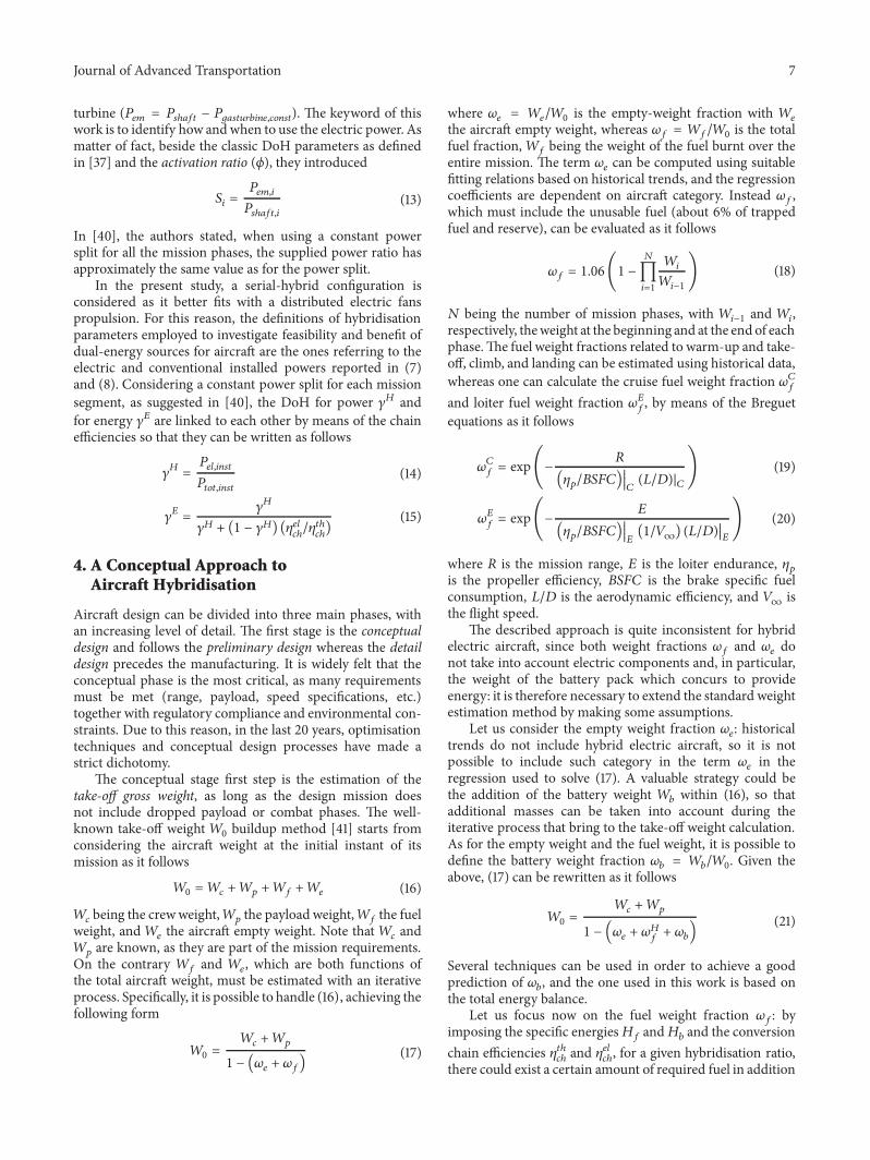
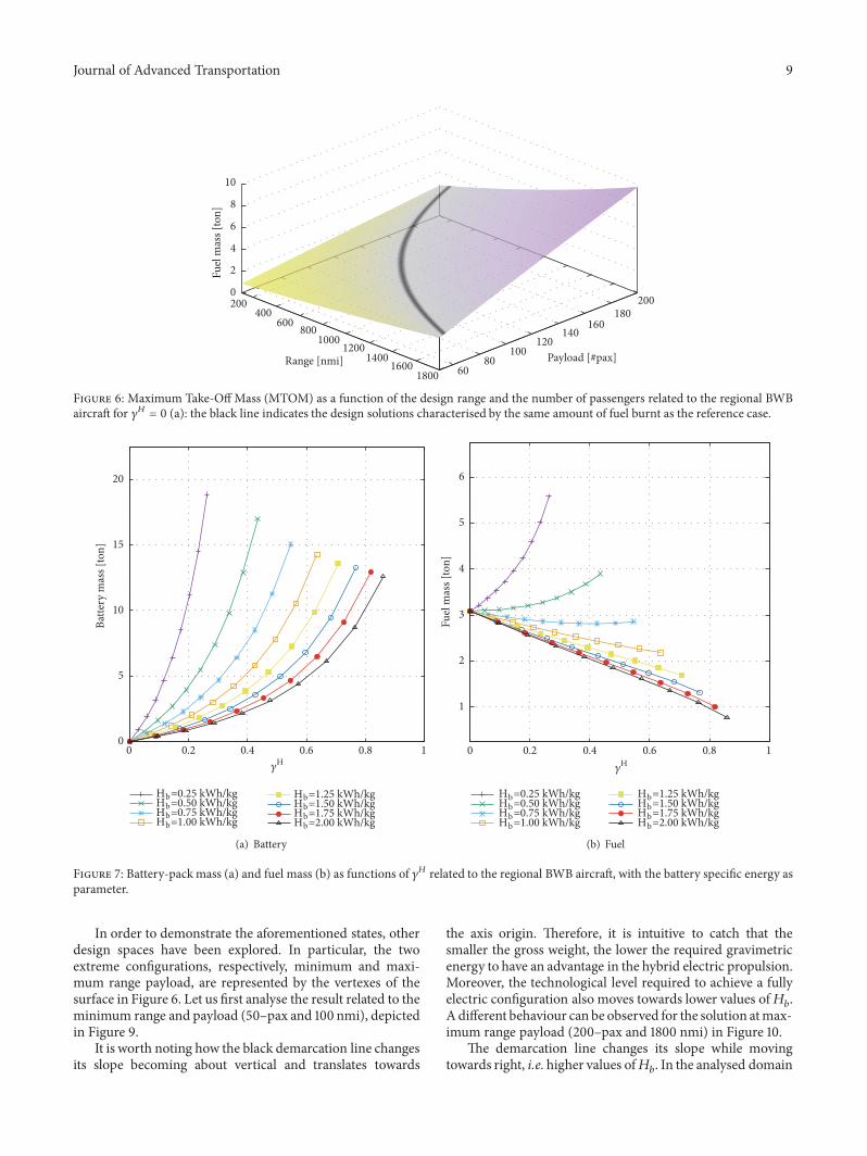

International Journal of
AerospaceEngineeringHindawiwwwhindawicom Volume 2018
RoboticsJournal of
Hindawiwwwhindawicom Volume 2018
Hindawiwwwhindawicom Volume 2018
Active and Passive Electronic Components
VLSI Design
Hindawiwwwhindawicom Volume 2018
Hindawiwwwhindawicom Volume 2018
Shock and Vibration
Hindawiwwwhindawicom Volume 2018
Civil EngineeringAdvances in
Acoustics and VibrationAdvances in
Hindawiwwwhindawicom Volume 2018
Hindawiwwwhindawicom Volume 2018
Electrical and Computer Engineering
Journal of
Advances inOptoElectronics
Hindawiwwwhindawicom
Volume 2018
Hindawi Publishing Corporation httpwwwhindawicom Volume 2013Hindawiwwwhindawicom
The Scientific World Journal
Volume 2018
Control Scienceand Engineering
Journal of
Hindawiwwwhindawicom Volume 2018
Hindawiwwwhindawicom
Journal ofEngineeringVolume 2018
SensorsJournal of
Hindawiwwwhindawicom Volume 2018
International Journal of
RotatingMachinery
Hindawiwwwhindawicom Volume 2018
Modelling ampSimulationin EngineeringHindawiwwwhindawicom Volume 2018
Hindawiwwwhindawicom Volume 2018
Chemical EngineeringInternational Journal of Antennas and
Propagation
International Journal of
Hindawiwwwhindawicom Volume 2018
Hindawiwwwhindawicom Volume 2018
Navigation and Observation
International Journal of
Hindawi
wwwhindawicom Volume 2018
Advances in
Multimedia
Submit your manuscripts atwwwhindawicom