applying the process safety standards
DESCRIPTION
Safety standardTRANSCRIPT
Copyright exida Asia Pacific © 2014
Singapore +65 6222 5160 Vietnam +84 854 042 580Hong Kong +852 2633 7727Australia / NZL +64 3 472 7707Germany +49 89 4900 0547USA +1 215 453 1720
Canada +1 403 475 1943United Kingdom +44 2476 456 195Netherlands +31 318 414 505Switzerland +41 22 364 14 34Mexico +52 55 5611 9858South Africa +27 31 267 1564
Exida Contacts
Applying the Process Safety StandardsSteve Burke, CFSE
The Representative Office of exida Asia Pacific Pte. Ltd. in Ho Chi Minh city
Copyright exida Asia Pacific © 2014 [email protected] 22
What is…?
Today’s Objective– Introduce Process Safety Concepts and Essential Principles
Standards to help with design a Safety Instrumented System (SIS) Determine level of safety performance; Safety Integrity Level (SIL) Safety Requirement Specification (SRS) Safety Instrumented Function (SIF) Design and Equipment Selection Verification and Validation of your SIF design Overview of CyberSeurity Overview of Alarm Management
– Who are exida and what we do…
Copyright exida Asia Pacific © 2014 [email protected] 44
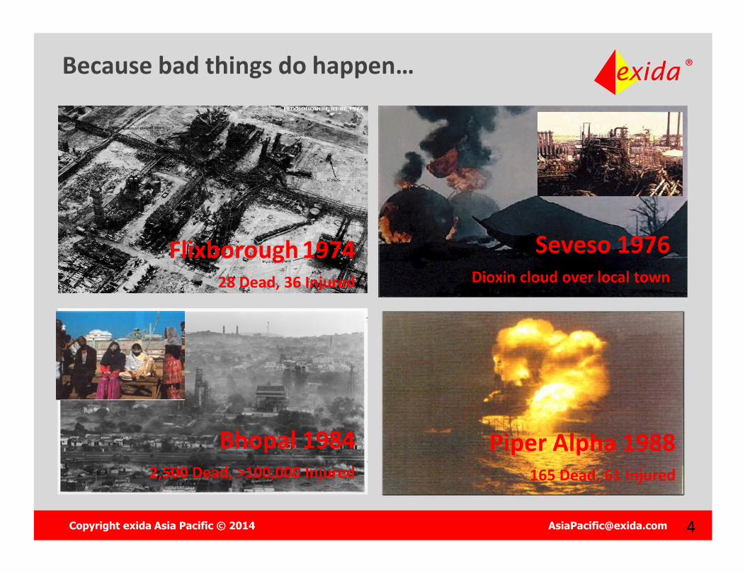
Because bad things do happen…
Bhopal 19842,500 Dead, >100,000 Injured
Flixborough 197428 Dead, 36 Injured
Seveso 1976Dioxin cloud over local town
Piper Alpha 1988165 Dead, 61 Injured
Copyright exida Asia Pacific © 2014 [email protected] 55
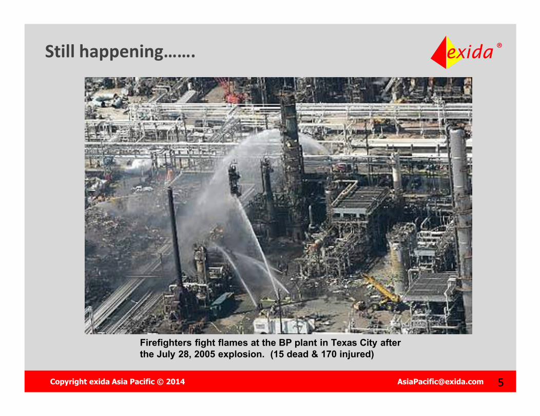
Still happening…….
Firefighters fight flames at the BP plant in Texas City after the July 28, 2005 explosion. (15 dead & 170 injured)
Copyright exida Asia Pacific © 2014 [email protected] 66
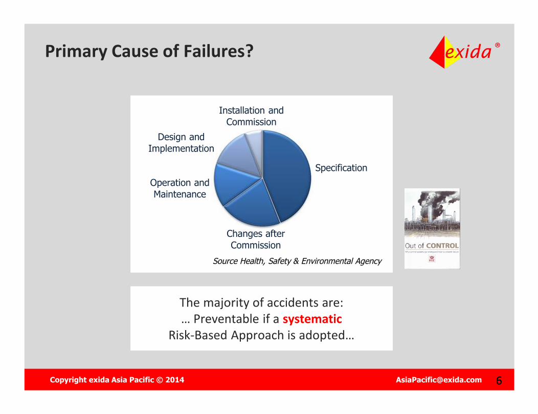
Primary Cause of Failures?
Specification
Changes after Commission
Operation and Maintenance
Design and Implementation
Installation and Commission
Source Health, Safety & Environmental Agency
The majority of accidents are:… Preventable if a systematic
Risk-Based Approach is adopted…
The majority of accidents are:… Preventable if a systematic
Risk-Based Approach is adopted…
Copyright exida Asia Pacific © 2014 [email protected] 77
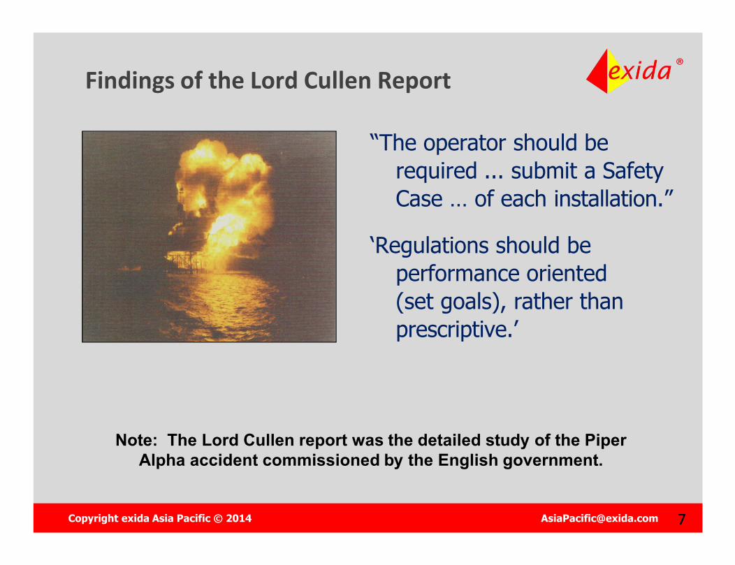
Findings of the Lord Cullen Report
“The operator should be required ... submit a Safety Case … of each installation.”
‘Regulations should be performance oriented (set goals), rather than prescriptive.’
Note: The Lord Cullen report was the detailed study of the Piper Alpha accident commissioned by the English government.
Copyright exida Asia Pacific © 2014 [email protected] 99
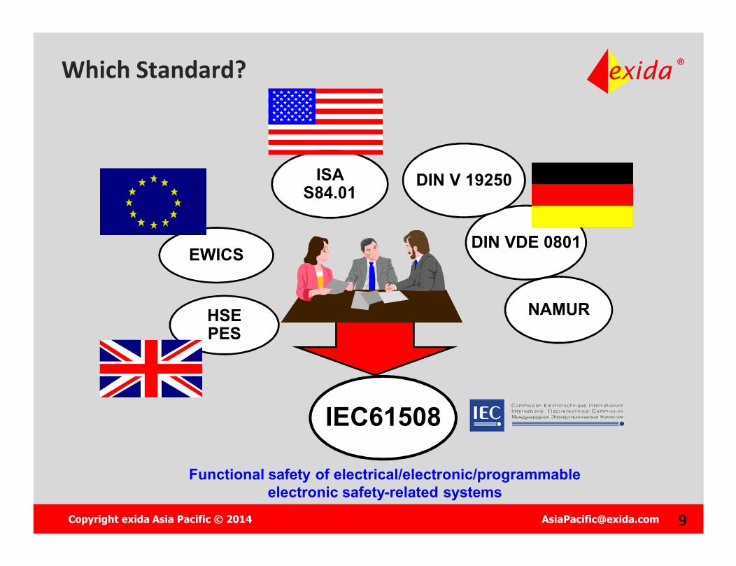
Which Standard?
DIN VDE 0801
DIN V 19250
NAMUR
ISAS84.01
HSEPES
EWICS
IEC61508
Functional safety of electrical/electronic/programmable electronic safety-related systems
Copyright exida Asia Pacific © 2014 [email protected] 1010
Which Standard?
IEC 61508Functional Safety for E/E/PES Safety Related Systems
IEC 61508Functional Safety for E/E/PES Safety Related Systems
Copyright exida Asia Pacific © 2014 [email protected] 1111
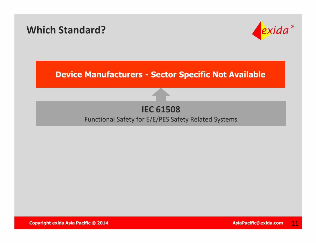
Device Manufacturers - Sector Specific Not AvailableDevice Manufacturers - Sector Specific Not Available
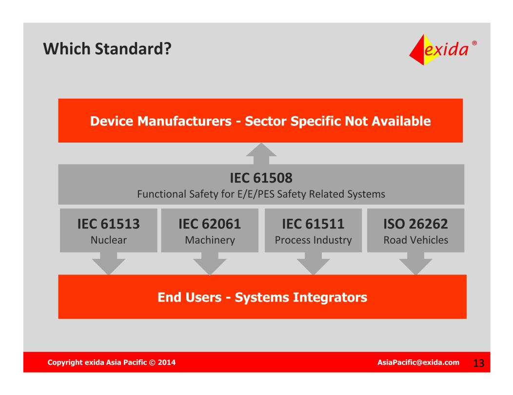
Which Standard?
IEC 61508Functional Safety for E/E/PES Safety Related Systems
IEC 61508Functional Safety for E/E/PES Safety Related Systems
Copyright exida Asia Pacific © 2014 [email protected] 1212
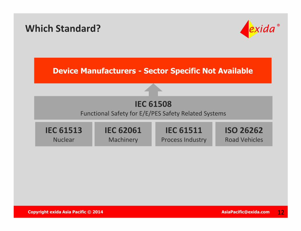
Device Manufacturers - Sector Specific Not AvailableDevice Manufacturers - Sector Specific Not Available
Which Standard?
IEC 61513Nuclear
IEC 61513Nuclear
IEC 61511Process Industry
IEC 61511Process Industry
IEC 61508Functional Safety for E/E/PES Safety Related Systems
IEC 61508Functional Safety for E/E/PES Safety Related Systems
ISO 26262Road VehiclesISO 26262Road Vehicles
IEC 62061Machinery
IEC 62061Machinery
Copyright exida Asia Pacific © 2014 [email protected] 1313
Device Manufacturers - Sector Specific Not AvailableDevice Manufacturers - Sector Specific Not Available
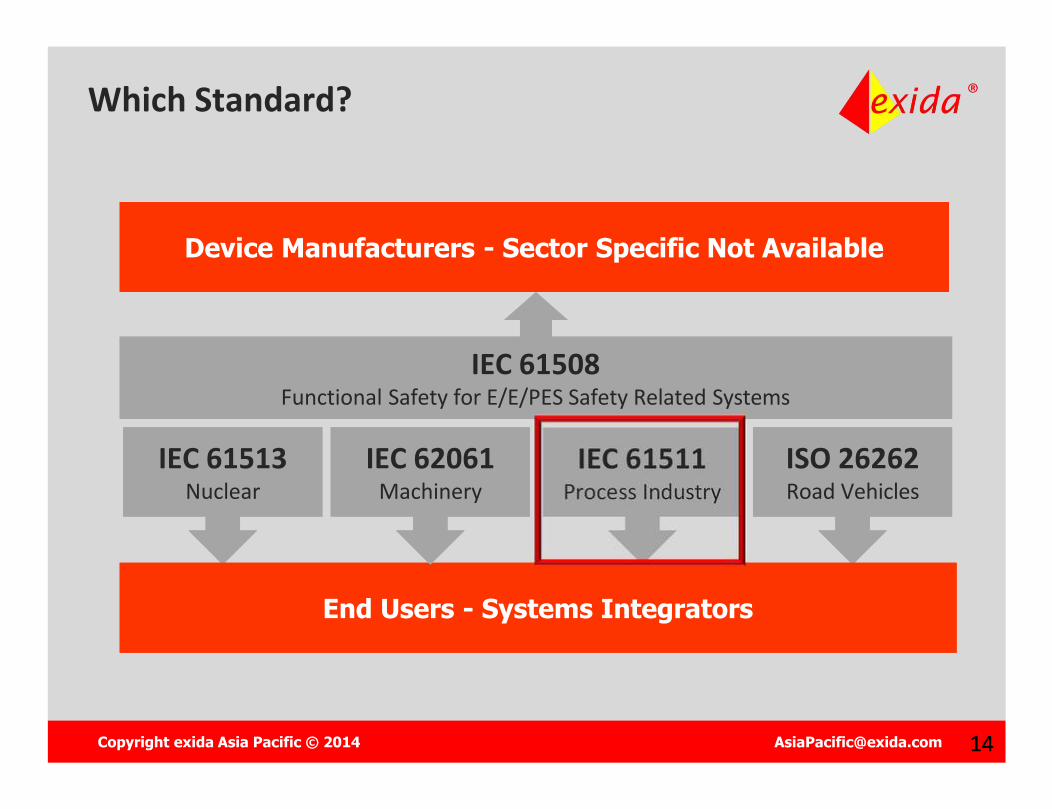
Which Standard?
IEC 61513Nuclear
IEC 61513Nuclear
IEC 61511Process Industry
IEC 61511Process Industry
IEC 61508Functional Safety for E/E/PES Safety Related Systems
IEC 61508Functional Safety for E/E/PES Safety Related Systems
ISO 26262Road VehiclesISO 26262Road Vehicles
End Users - Systems IntegratorsEnd Users - Systems Integrators
IEC 62061Machinery
IEC 62061Machinery
Copyright exida Asia Pacific © 2014 [email protected] 1414
Device Manufacturers - Sector Specific Not AvailableDevice Manufacturers - Sector Specific Not Available
Which Standard?
IEC 61513Nuclear
IEC 61513Nuclear
IEC 61511Process Industry
IEC 61511Process Industry
IEC 61508Functional Safety for E/E/PES Safety Related Systems
IEC 61508Functional Safety for E/E/PES Safety Related Systems
ISO 26262Road VehiclesISO 26262Road Vehicles
End Users - Systems IntegratorsEnd Users - Systems Integrators
IEC 62061Machinery
IEC 62061Machinery

Copyright exida Asia Pacific © 2014 [email protected] 1515
Relationship IEC 61508 – IEC 61511
Manufacturers and Suppliers of Devices
IEC 61508
Manufacturers and Suppliers of Devices
IEC 61508
Safety Instrumented System designers, Integrators and users
IEC 61511
Safety Instrumented System designers, Integrators and users
IEC 61511
Process Sector Safety Instrumented System StandardsProcess Sector Safety Instrumented System Standards
Copyright exida Asia Pacific © 2014 [email protected] 16
Copyright © 2013 exida
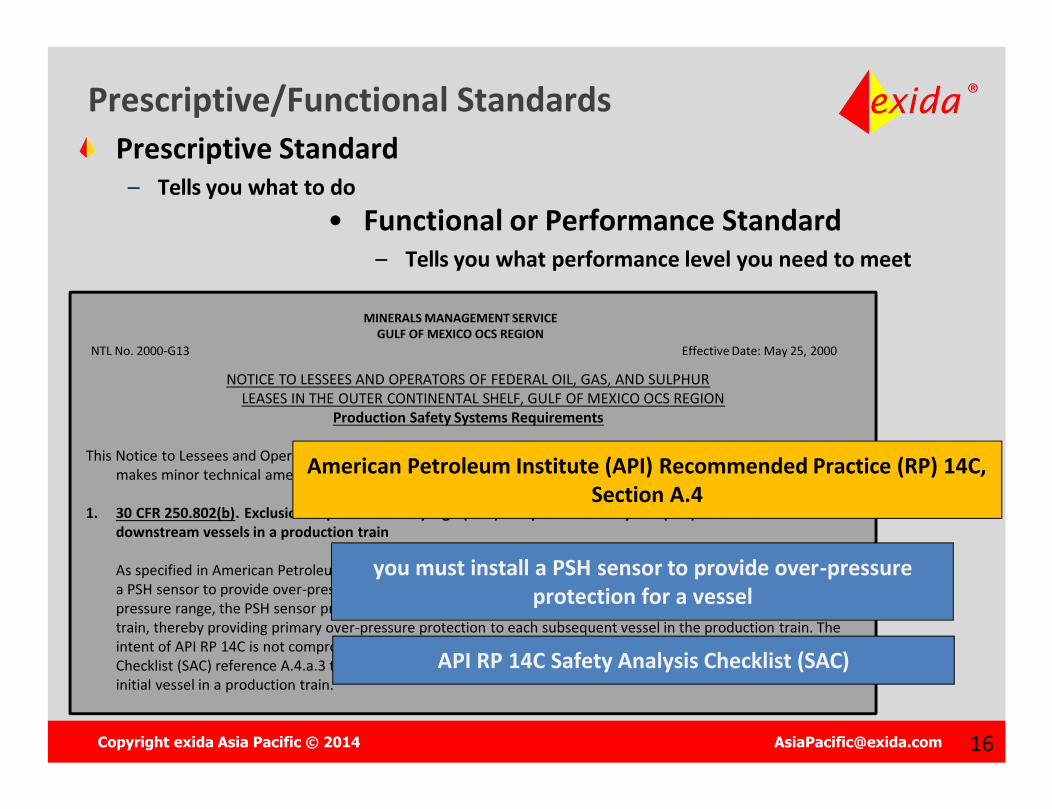
Prescriptive/Functional StandardsPrescriptive Standard
– Tells you what to do
MINERALS MANAGEMENT SERVICEGULF OF MEXICO OCS REGION
NTL No. 2000-G13 Effective Date: May 25, 2000
NOTICE TO LESSEES AND OPERATORS OF FEDERAL OIL, GAS, AND SULPHURLEASES IN THE OUTER CONTINENTAL SHELF, GULF OF MEXICO OCS REGION
Production Safety Systems Requirements
This Notice to Lessees and Operators (NTL) supersedes NTL No. 2000-G09, dated March 29, 2000, on this subject. It makes minor technical amendments and corrects some cited authorities.
1. 30 CFR 250.802(b). Exclusion of pressure safety high (PSH) and pressure safety low (PSL) sensors on downstream vessels in a production train
As specified in American Petroleum Institute (API) Recommended Practice (RP) 14C, Section A.4, you must install a PSH sensor to provide over-pressure protection for a vessel. If an entire production train operates in the same pressure range, the PSH sensor protecting the initial vessel will detect the highest pressure in the production train, thereby providing primary over-pressure protection to each subsequent vessel in the production train. The intent of API RP 14C is not compromised under this scenario. Therefore, you may use API RP 14C Safety Analysis Checklist (SAC) reference A.4.a.3 to exclude all subsequent PSH sensors other than the PSH sensor protecting the initial vessel in a production train.
you must install a PSH sensor to provide over-pressure protection for a vessel
American Petroleum Institute (API) Recommended Practice (RP) 14C, Section A.4
API RP 14C Safety Analysis Checklist (SAC)
• Functional or Performance Standard– Tells you what performance level you need to meet
Copyright exida Asia Pacific © 2014 [email protected] 1717
Copyright © 2013 exida
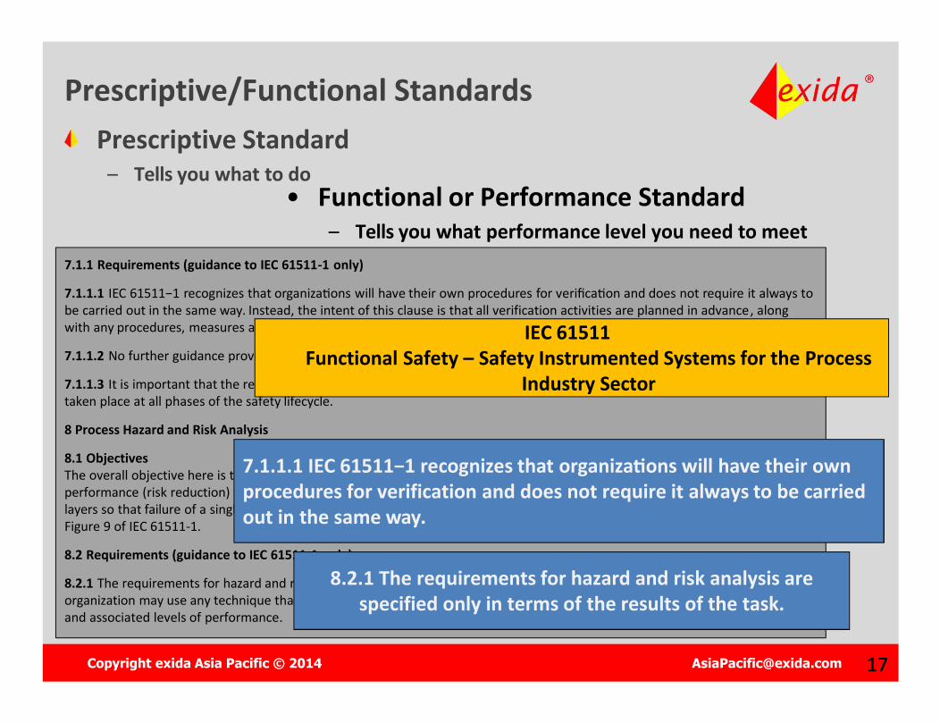
Prescriptive Standard– Tells you what to do
7.1.1 Requirements (guidance to IEC 61511-1 only)
7.1.1.1 IEC 61511−1 recognizes that organiza�ons will have their own procedures for verifica�on and does not require it always to be carried out in the same way. Instead, the intent of this clause is that all verification activities are planned in advance, along with any procedures, measures and techniques that are to be used.
7.1.1.2 No further guidance provided.
7.1.1.3 It is important that the results of verification are available so that it can be demonstrated that effective verification hastaken place at all phases of the safety lifecycle.
8 Process Hazard and Risk Analysis
8.1 ObjectivesThe overall objective here is to establish the need for safety functions (e.g., protection layers) together with associated levels of performance (risk reduction) that are needed to ensure a safe process. It is normal in the process sector to have multiple safety layers so that failure of a single layer will not lead to or allow a harmful consequence. Typical safety layers are represented in Figure 9 of IEC 61511-1.
8.2 Requirements (guidance to IEC 61511-1 only)
8.2.1 The requirements for hazard and risk analysis are specified only in terms of the results of the task. This means that an organization may use any technique that it considers to be effective, provided it results in a clear description of safety functions and associated levels of performance.
7.1.1.1 IEC 61511−1 recognizes that organiza�ons will have their own procedures for verification and does not require it always to be carried out in the same way.
IEC 61511Functional Safety – Safety Instrumented Systems for the Process
Industry Sector
8.2.1 The requirements for hazard and risk analysis are specified only in terms of the results of the task.
• Functional or Performance Standard– Tells you what performance level you need to meet
Prescriptive/Functional Standards
Copyright exida Asia Pacific © 2014 [email protected] 18
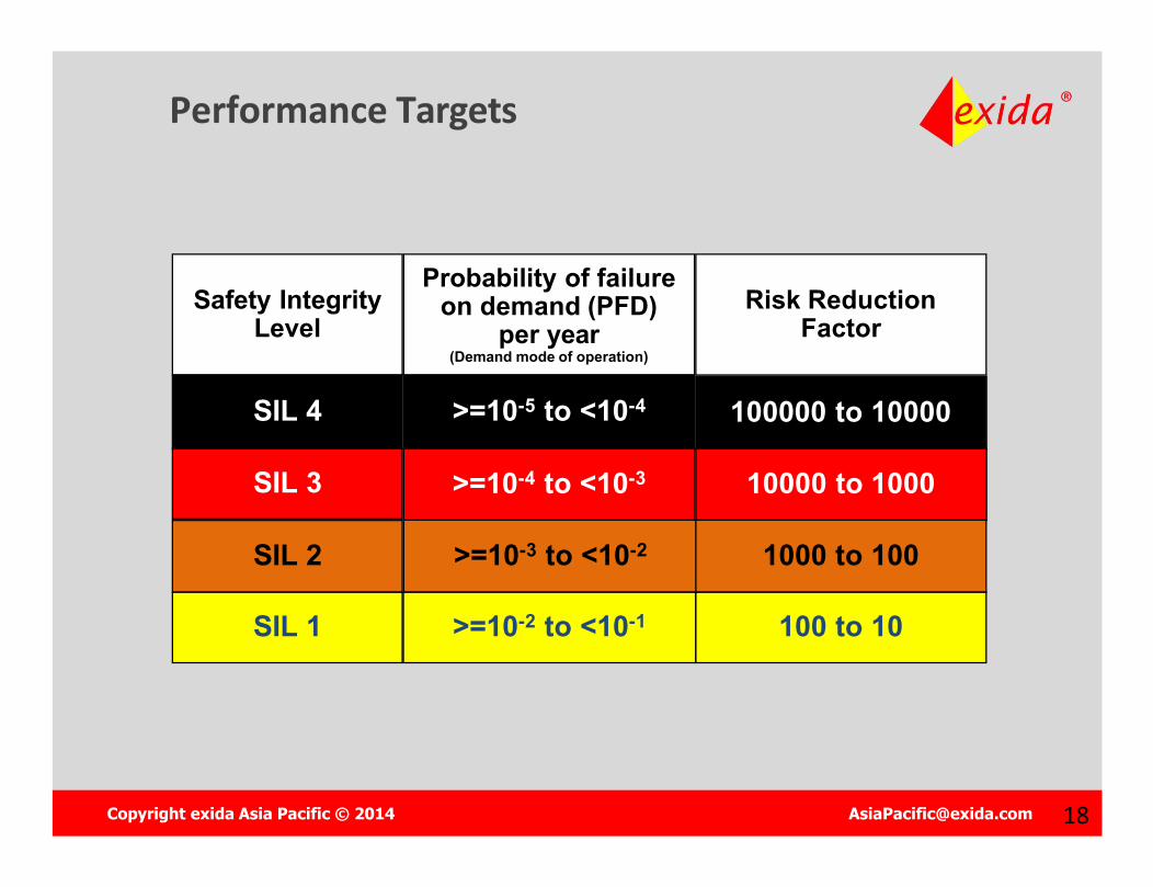
Performance Targets
Safety Integrity Level
Probability of failure on demand (PFD)
per year(Demand mode of operation)
Risk Reduction Factor
SIL 4 >=10-5 to <10-4 100000 to 10000
SIL 3 >=10-4 to <10-3 10000 to 1000
SIL 2 >=10-3 to <10-2 1000 to 100
SIL 1 >=10-2 to <10-1 100 to 10
Copyright exida Asia Pacific © 2014 [email protected] 20
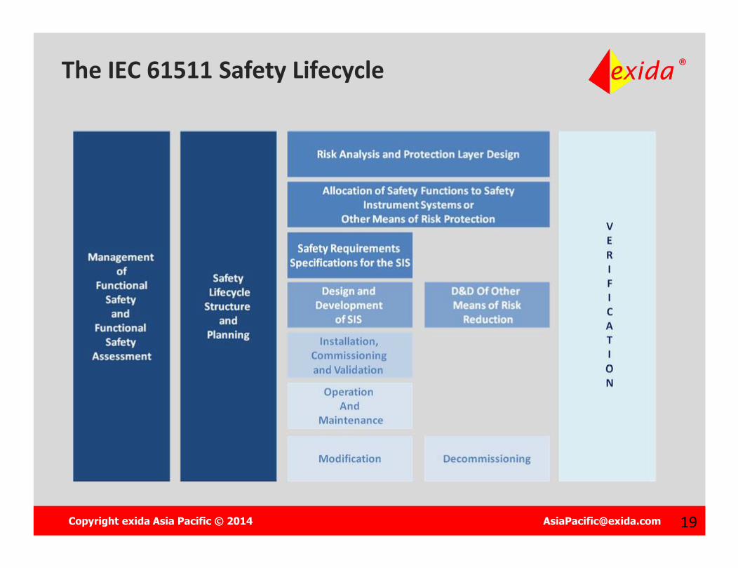
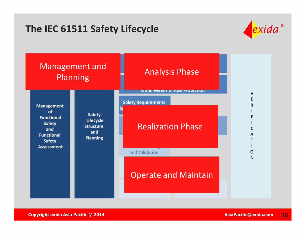
The IEC 61511 Safety Lifecycle
Management and Planning
Management and Planning Analysis PhaseAnalysis Phase
Realization PhaseRealization Phase
Operate and MaintainOperate and Maintain
Copyright exida Asia Pacific © 2014 [email protected] 21
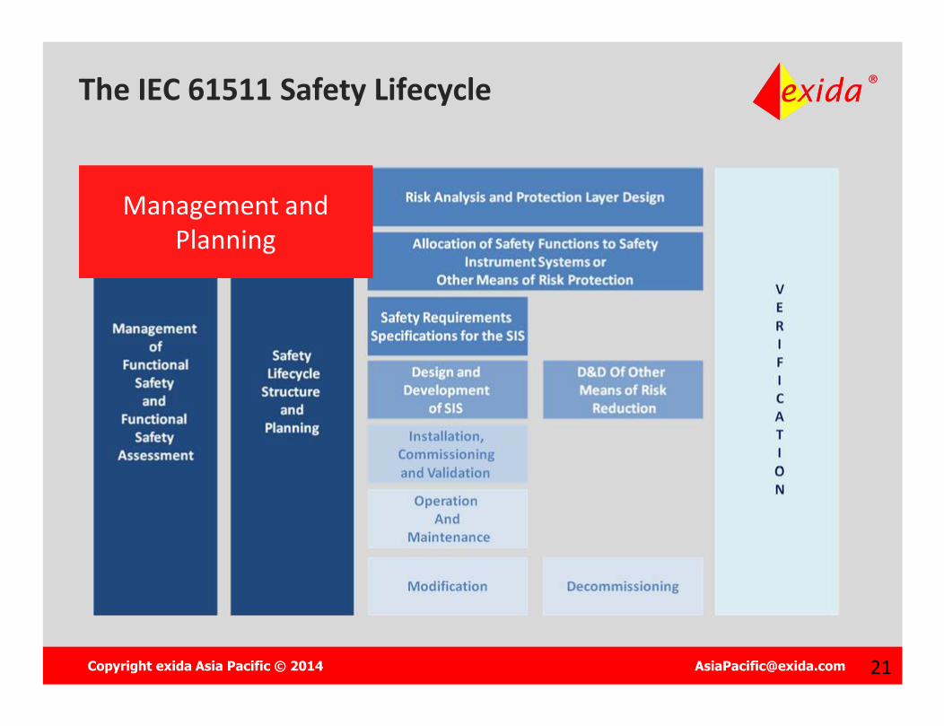
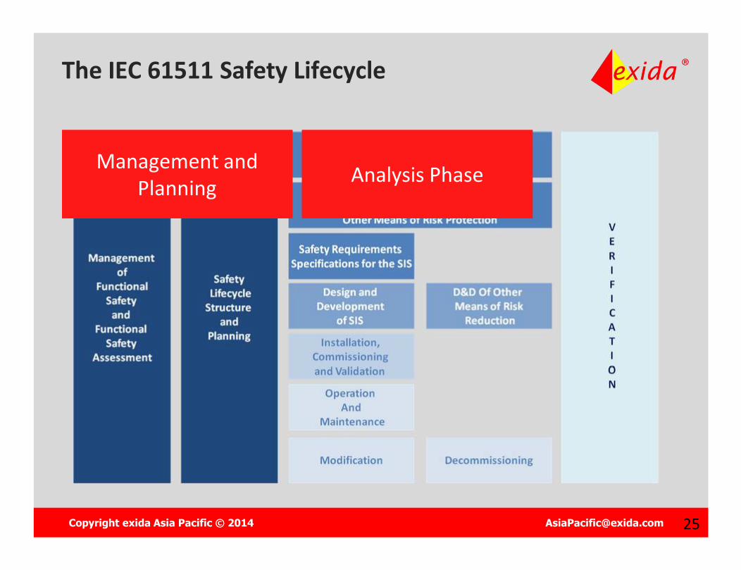
The IEC 61511 Safety Lifecycle
Management and Planning
Management and Planning
Copyright exida Asia Pacific © 2014 [email protected] 22
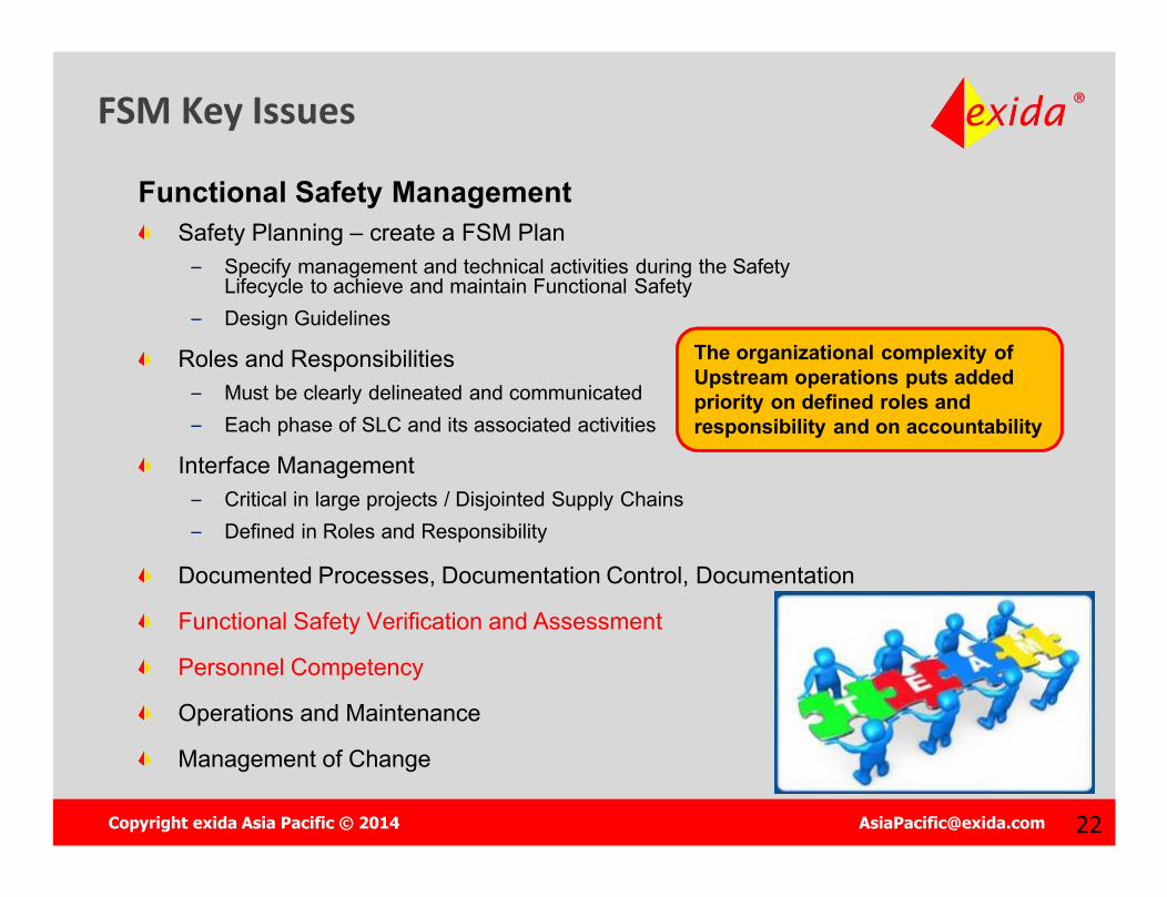
FSM Key Issues
Functional Safety ManagementSafety Planning – create a FSM Plan
– Specify management and technical activities during the Safety Lifecycle to achieve and maintain Functional Safety
– Design Guidelines
Roles and Responsibilities– Must be clearly delineated and communicated– Each phase of SLC and its associated activities
Interface Management– Critical in large projects / Disjointed Supply Chains– Defined in Roles and Responsibility
Documented Processes, Documentation Control, Documentation
Functional Safety Verification and Assessment
Personnel Competency
Operations and Maintenance
Management of Change
The organizational complexity of Upstream operations puts added priority on defined roles and responsibility and on accountability
Copyright exida Asia Pacific © 2014 [email protected] 23
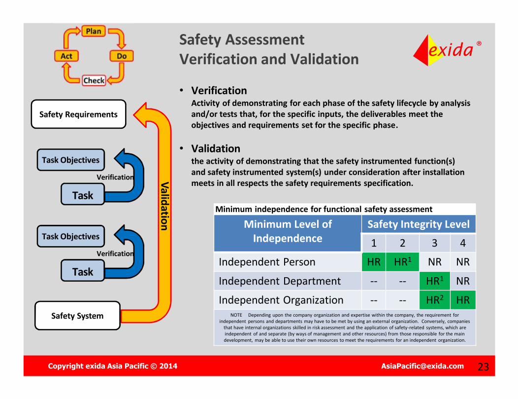
Minimum independence for functional safety assessment
Safety Assessment Verification and Validation
Minimum Level of Independence
Safety Integrity Level1 2 3 4
Independent Person HR HR1 NR NRIndependent Department -- -- HR1 NRIndependent Organization -- -- HR2 HR
NOTE Depending upon the company organization and expertise within the company, the requirement for independent persons and departments may have to be met by using an external organization. Conversely, companies
that have internal organizations skilled in risk assessment and the application of safety-related systems, which are independent of and separate (by ways of management and other resources) from those responsible for the main development, may be able to use their own resources to meet the requirements for an independent organization.
• VerificationActivity of demonstrating for each phase of the safety lifecycle by analysis and/or tests that, for the specific inputs, the deliverables meet the objectives and requirements set for the specific phase.
• Validation the activity of demonstrating that the safety instrumented function(s) and safety instrumented system(s) under consideration after installation meets in all respects the safety requirements specification.
Safety System
Safety Requirements
Task
Task Objectives
Verification
Task
Task Objectives
Verification
Validation

Copyright exida Asia Pacific © 2014 [email protected] 24
Personnel Competency
Training, experience, and qualifications should all be addressed and documented
– System engineering knowledge– Safety engineering knowledge– Legal and regulatory requirements knowledge– More critical for novel systems or high SIL requirements
“Persons, departments, or organizations involved in safety lifecycle activities shall be competent to carry out the activities for which they are accountable.”
-IEC 61511, Part 1, Paragraph 5.2.2.2
Copyright exida Asia Pacific © 2014 [email protected] 25
The IEC 61511 Safety Lifecycle
Management and Planning
Management and Planning Analysis PhaseAnalysis Phase
Copyright exida Asia Pacific © 2014 [email protected] 26
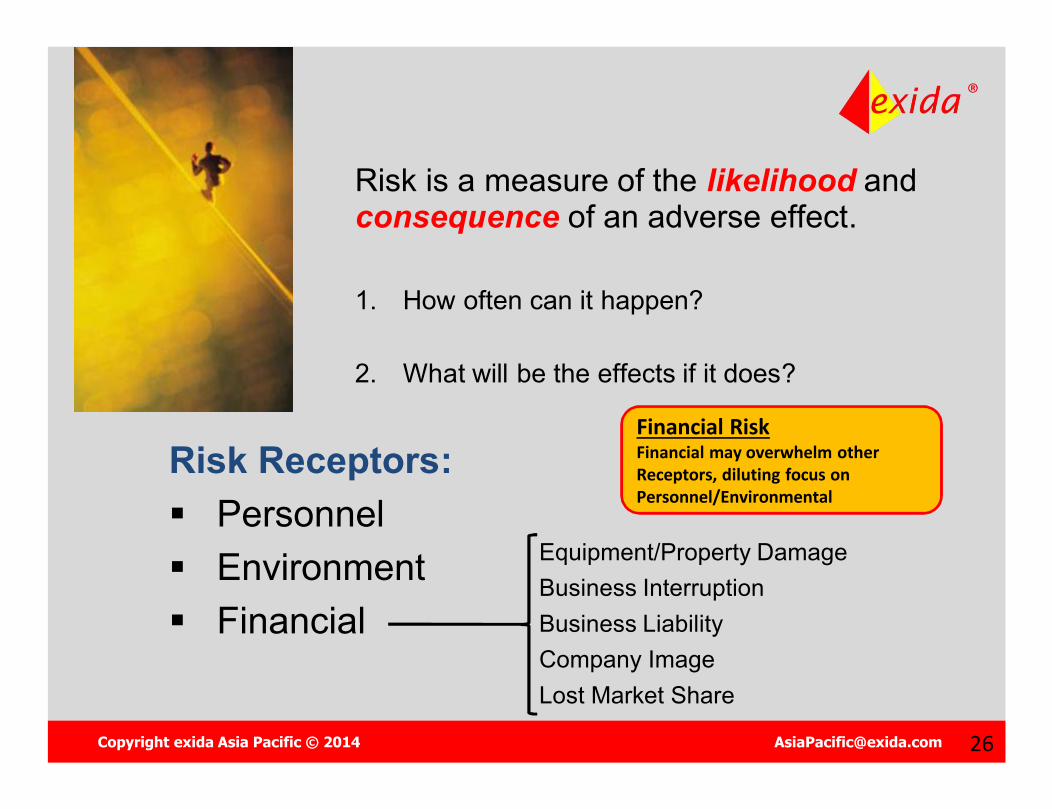
What is Risk?
Risk is a measure of the likelihood and consequence of an adverse effect.
1. How often can it happen?
2. What will be the effects if it does?
Risk Receptors: Personnel Environment Financial
Equipment/Property DamageBusiness InterruptionBusiness LiabilityCompany ImageLost Market Share
Financial RiskFinancial may overwhelm other Receptors, diluting focus on Personnel/Environmental
Copyright exida Asia Pacific © 2014 [email protected] 27
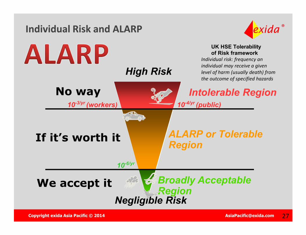
Individual Risk and ALARP
Negligible Risk
High Risk
10-3/yr (workers) 10-4/yr (public)
10-6/yr
Intolerable Region
ALARP or Tolerable Region
Broadly Acceptable Region
No way
If it’s worth it
We accept it
Individual risk: frequency an individual may receive a given level of harm (usually death) from the outcome of specified hazards
UK HSE Tolerability of Risk framework
Copyright exida Asia Pacific © 2014 [email protected] 2828
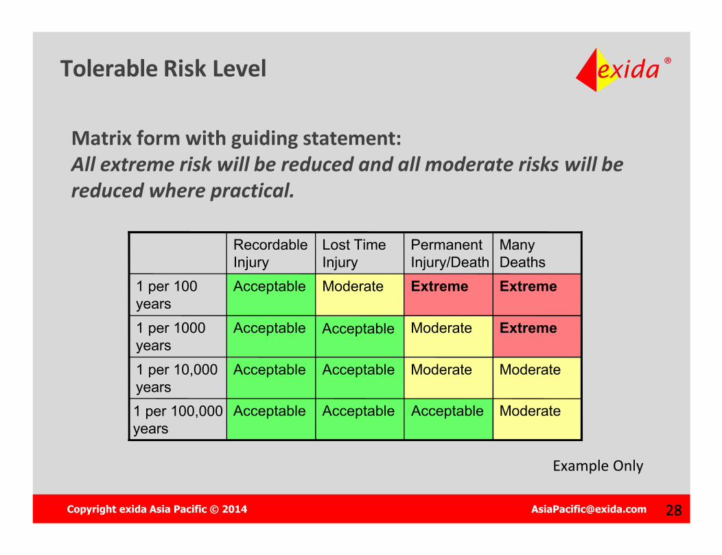
Tolerable Risk Level
Matrix form with guiding statement:All extreme risk will be reduced and all moderate risks will be reduced where practical.
Acceptable
Acceptable ModerateAcceptableAcceptable1 per 100,000 years
ModerateModerateAcceptableAcceptable1 per 10,000 years
ExtremeModerateAcceptable1 per 1000 years
ExtremeExtremeModerateAcceptable1 per 100 years
Many Deaths
Permanent Injury/Death
Lost Time Injury
Recordable Injury
Example Only
Copyright exida Asia Pacific © 2014 [email protected] 29
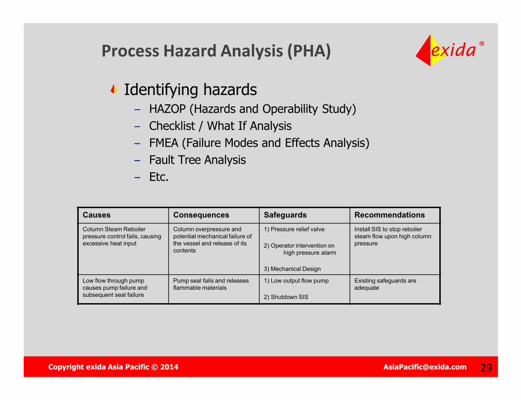
Process Hazard Analysis (PHA)
Identifying hazards– HAZOP (Hazards and Operability Study)– Checklist / What If Analysis– FMEA (Failure Modes and Effects Analysis)– Fault Tree Analysis– Etc.
Causes Consequences Safeguards RecommendationsColumn Steam Reboiler pressure control fails, causing excessive heat input
Column overpressure and potential mechanical failure of the vessel and release of its contents
1) Pressure relief valve
2) Operator intervention on high pressure alarm
3) Mechanical Design
Install SIS to stop reboilersteam flow upon high column pressure
Low flow through pump causes pump failure and subsequent seal failure
Pump seal fails and releases flammable materials
1) Low output flow pump
2) Shutdown SIS
Existing safeguards are adequate
Copyright exida Asia Pacific © 2014 [email protected] 31
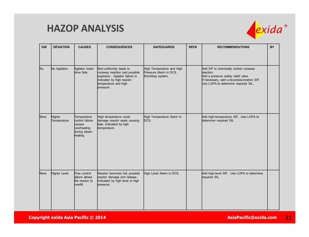
HAZOP ANALYSIS GW DEVIATION CAUSES CONSEQUENCES SAFEGUARDS REF# RECOMMENDATIONS BY
No No Agitation Agitator motor drive fails
Non-uniformity leads to runaway reaction and possible explosion. Agitator failure is indicated by high reactor temperature and high pressure.
High Temperature and High Pressure Alarm in DCS. Shortstop system.
Add SIF to chemically control runaway reaction. Add a pressure safety relief valveIf necessary, add a de-pressurization SIF. Use LOPA to determine required SIL.
More Higher Temperature
Temperature control failure causes overheating during steam heating
High temperature could damage reactor seals causing leak. Indicated by high temperature.
High Temperature Alarm in DCS.
Add high-temperature SIF. Use LOPA to determine required SIL
More Higher Level Flow control failure allows the reactor to overfill
Reactor becomes full, possible reactor damage and release. Indicated by high level or high pressure.
High Level Alarm in DCS. Add high-level SIF. Use LOPA to determine required SIL
Copyright exida Asia Pacific © 2014 [email protected] 32
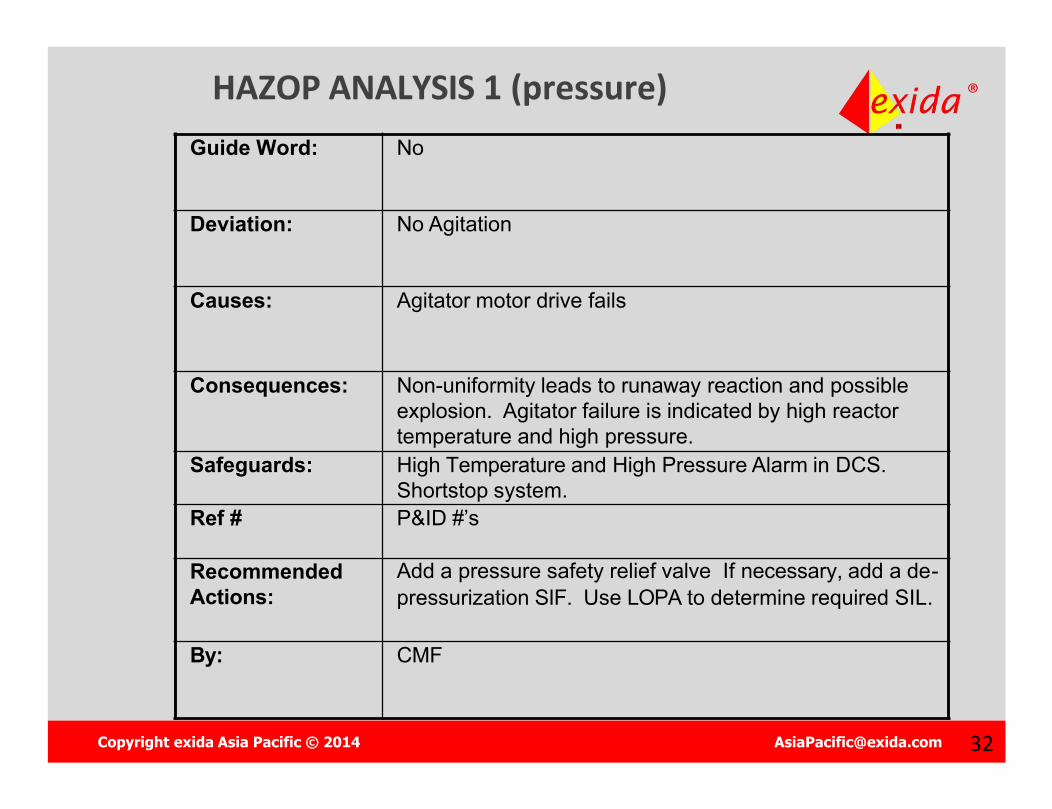
HAZOP ANALYSIS 1 (pressure)Guide Word: No
Deviation: No Agitation
Causes: Agitator motor drive fails
Consequences: Non-uniformity leads to runaway reaction and possible explosion. Agitator failure is indicated by high reactor temperature and high pressure.
Safeguards: High Temperature and High Pressure Alarm in DCS. Shortstop system.
Ref # P&ID #’s
Recommended Actions:
Add a pressure safety relief valve If necessary, add a de-pressurization SIF. Use LOPA to determine required SIL.
By: CMF
Copyright exida Asia Pacific © 2014 [email protected] 34
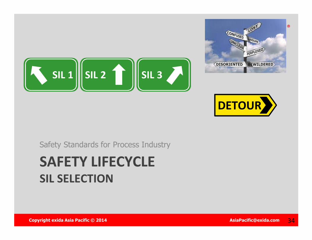
SAFETY LIFECYCLESIL SELECTION
Safety Standards for Process Industry
SIL 3SIL 1 SIL 2
DETOUR

Copyright exida Asia Pacific © 2014 [email protected] 35
Safety Integrity Level
Safety Integrity Level
SIL 4
SIL 3
SIL 2
SIL 1
Used THREE ways:
1. To establish risk reduction requirements
2. To set probabilistic limits for hardware random failure
3. To establish engineering procedures to prevent systematic design errors
Copyright exida Asia Pacific © 2014 [email protected] 36
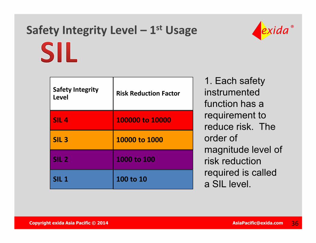
Safety Integrity Level – 1st Usage
Safety Integrity Level
SIL 4
SIL 3
SIL 2
SIL 1
Risk Reduction Factor
100000 to 10000
10000 to 1000
1000 to 100
100 to 10
1. Each safety instrumented function has a requirement to reduce risk. The order of magnitude level of risk reduction required is called a SIL level.
Copyright exida Asia Pacific © 2014 [email protected] 3737
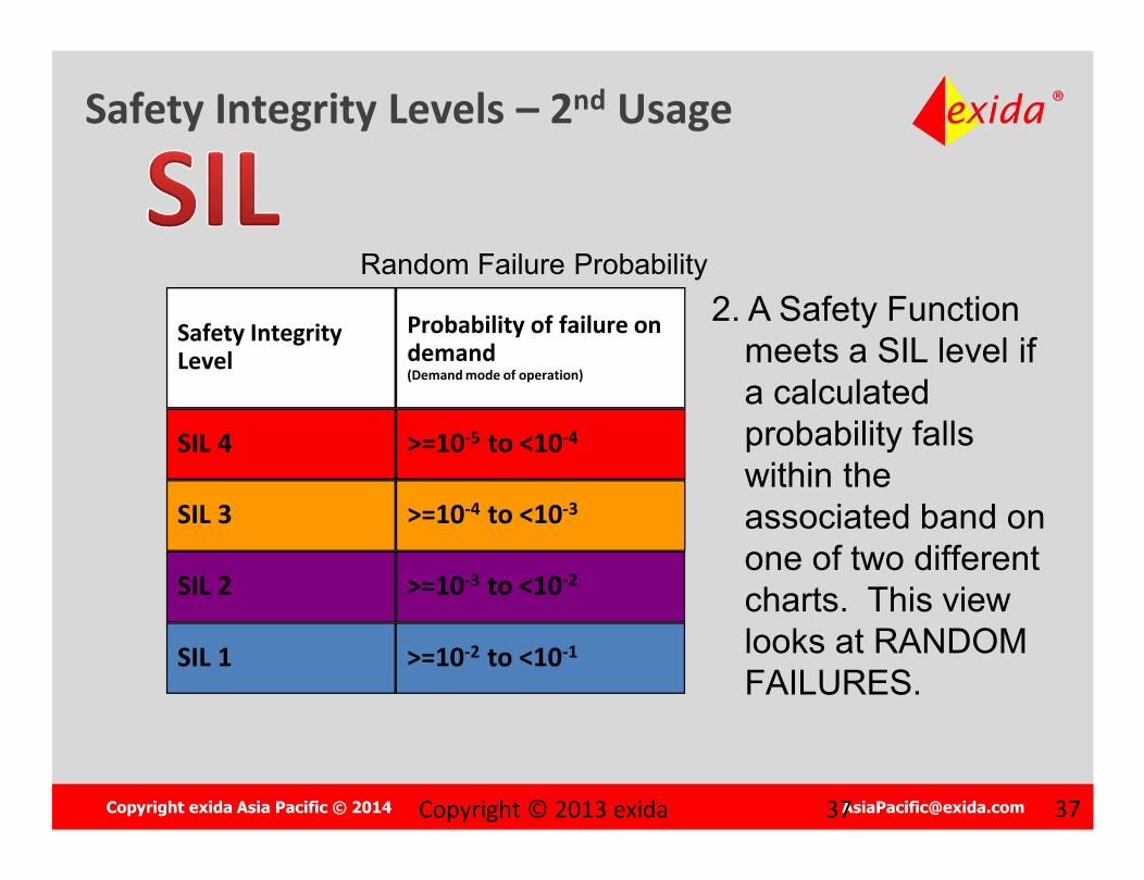
Safety Integrity Levels – 2nd Usage
Safety Integrity Level
SIL 4
SIL 3
SIL 2
SIL 1
Probability of failure on demand(Demand mode of operation)
>=10-5 to <10-4
>=10-4 to <10-3
>=10-3 to <10-2
>=10-2 to <10-1
Random Failure Probability2. A Safety Function
meets a SIL level if a calculated probability falls within the associated band on one of two different charts. This view looks at RANDOM FAILURES.
Copyright © 2013 exida
Copyright exida Asia Pacific © 2014 [email protected] 38
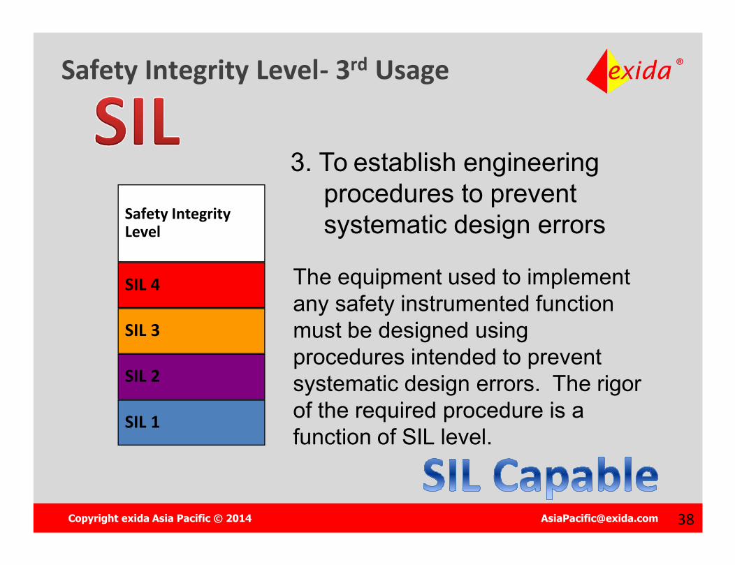
Safety Integrity Level- 3rd Usage
Safety Integrity Level
SIL 4
SIL 3
SIL 2
SIL 1
3. To establish engineering procedures to prevent systematic design errors
The equipment used to implement any safety instrumented function must be designed using procedures intended to prevent systematic design errors. The rigor of the required procedure is a function of SIL level.
Copyright exida Asia Pacific © 2014 [email protected] 39
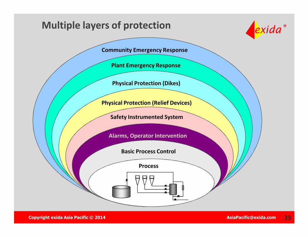
Multiple layers of protection
Community Emergency Response
Plant Emergency Response
Physical Protection (Dikes)
Physical Protection (Relief Devices)
Safety Instrumented System
Alarms, Operator Intervention
Basic Process Control
Process
Copyright exida Asia Pacific © 2014 [email protected] 4040
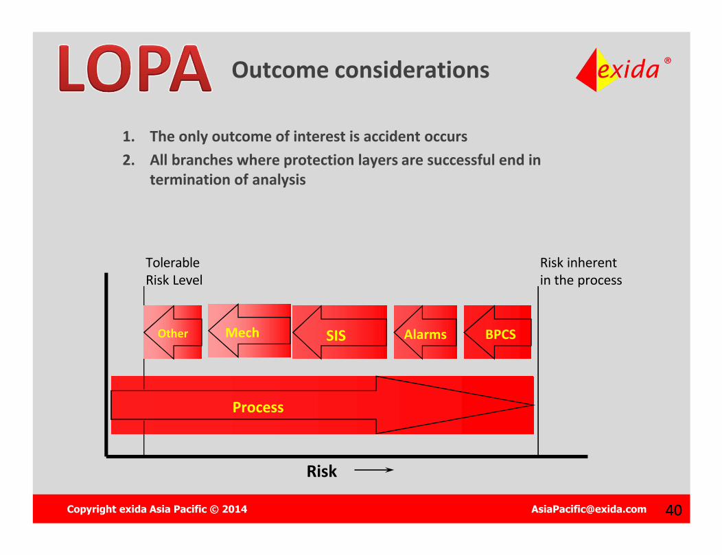
Outcome considerations
1. The only outcome of interest is accident occurs2. All branches where protection layers are successful end in
termination of analysis
Process
Risk
Risk inherent in the process
Tolerable Risk Level
BPCSAlarmsSISOther Mech
Copyright exida Asia Pacific © 2014 [email protected] 4141
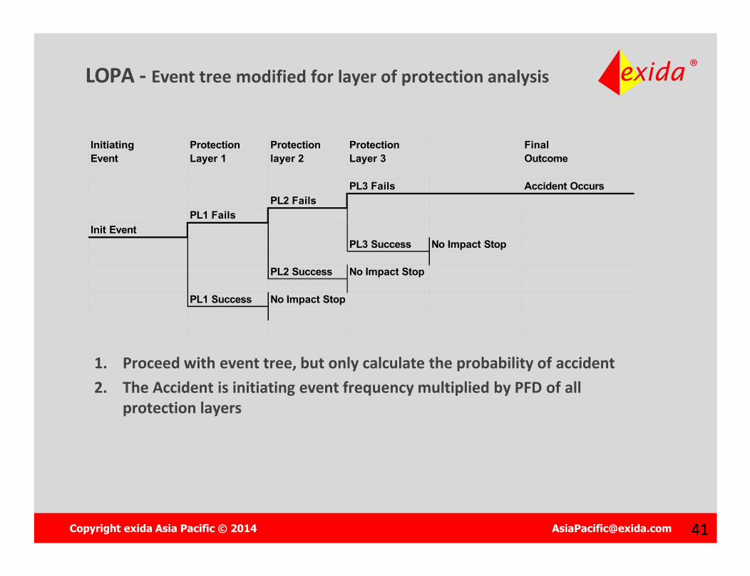
LOPA - Event tree modified for layer of protection analysis
Initiating Protection Protection Protection Final Event Layer 1 layer 2 Layer 3 Outcome
PL3 Fails Accident OccursPL2 Fails
PL1 FailsInit Event
PL3 Success No Impact Stop
PL2 Success No Impact Stop
PL1 Success No Impact Stop
1. Proceed with event tree, but only calculate the probability of accident2. The Accident is initiating event frequency multiplied by PFD of all
protection layers
Copyright exida Asia Pacific © 2014 [email protected] 4242
Example 1 – Reactor Explosion LOPA
Draw the Layer of Protection Analysis Diagram for the following situation
– An accident whose consequence is an explosion due to runaway reactor caused by the agitator motor failure.
– The following layers of protection existBatch process only runs 5 times per yearThe operator responds to alarms and stops the processRunaway reaction cancelled by addition of ShortstopThe reactor has a pressure relief valve
Copyright exida Asia Pacific © 2014 [email protected] 4343
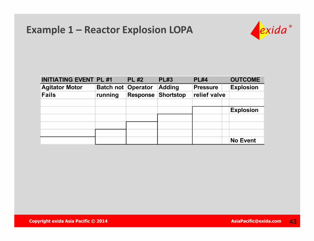
Example 1 – Reactor Explosion LOPA
INITIATING EVENT PL #1 PL #2 PL#3 PL#4 OUTCOMEAgitator Motor Batch not Operator Adding Pressure ExplosionFails running Response Shortstop relief valve
Explosion
No Event

Copyright exida Asia Pacific © 2014 [email protected] 4444
Example – Column Rupture LOPA
Quantify the accident frequency of the prior example– Agitator Motor fails once every 2 years
Failure Frequency is 0.5 /yr
– Protection Layer PFD are Batch Process not running, PFD = 0.29
5 batches/yr * 3weeks/batch * 7days/week * 24hours/day = 2520 operational hours = 29% of the year.
Operator response failure, PFD = 0.1 Shortstop failure, PFD = 0.1 Relief valve failure, PFD = 0.07
Copyright exida Asia Pacific © 2014 [email protected] 4545
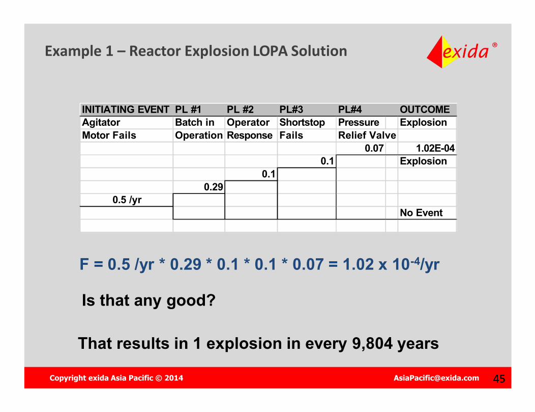
Example 1 – Reactor Explosion LOPA Solution
INITIATING EVENT PL #1 PL #2 PL#3 PL#4 OUTCOMEAgitator Batch in Operator Shortstop Pressure ExplosionMotor Fails Operation Response Fails Relief Valve
0.07 1.02E-040.1 Explosion
0.10.29
0.5 /yrNo Event
F = 0.5 /yr * 0.29 * 0.1 * 0.1 * 0.07 = 1.02 x 10⁻⁴/yr
That results in 1 explosion in every 9,804 years
Is that any good?
Copyright exida Asia Pacific © 2014 [email protected] 46
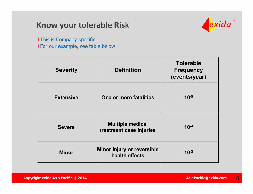
Know your tolerable RiskThis is Company specific.For our example, see table below:
Severity DefinitionTolerable
Frequency (events/year)
Extensive One or more fatalities 10-5
Severe Multiple medical treatment case injuries 10-4
Minor Minor injury or reversible health effects 10-3
Copyright exida Asia Pacific © 2014 [email protected] 4747
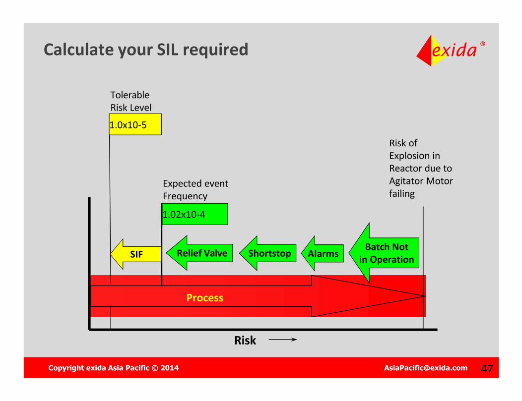
Calculate your SIL required
Process
Risk
Risk of Explosion in Reactor due to Agitator Motor failing
Tolerable Risk Level
Batch Notin OperationAlarmsShortstopRelief Valve
1.0x10⁻⁵
SIF
1.02x10⁻⁴
Expected event Frequency
Copyright exida Asia Pacific © 2014 [email protected] 4848
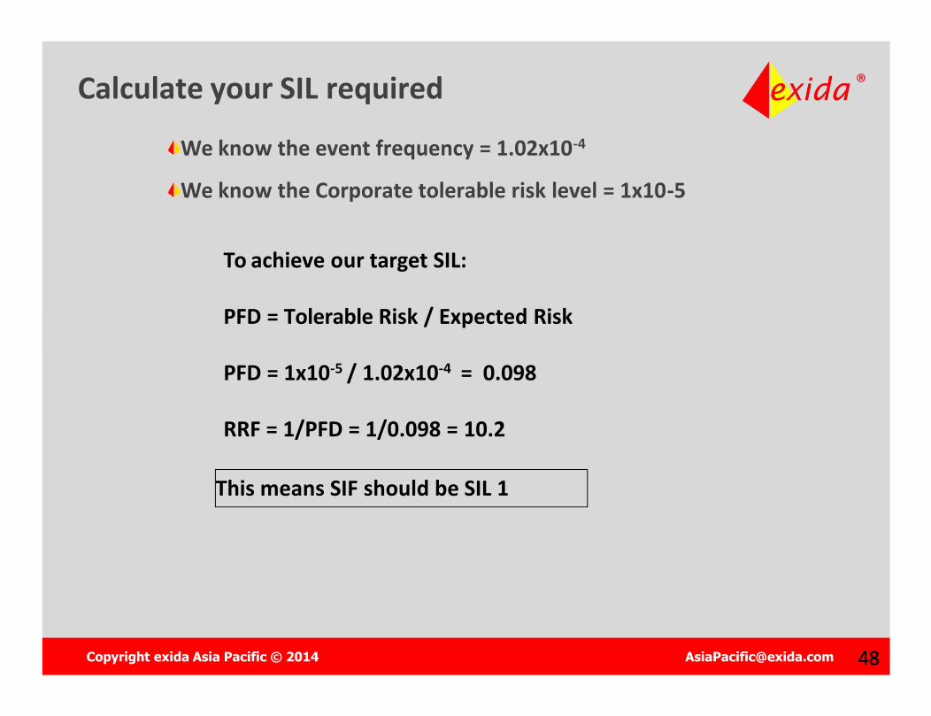
Calculate your SIL required
We know the event frequency = 1.02x10⁻⁴
We know the Corporate tolerable risk level = 1x10⁻⁵
To achieve our target SIL:
PFD = Tolerable Risk / Expected Risk
PFD = 1x10⁻⁵ / 1.02x10-4 = 0.098
RRF = 1/PFD = 1/0.098 = 10.2
This means SIF should be SIL 1
Copyright exida Asia Pacific © 2014 [email protected] 4949
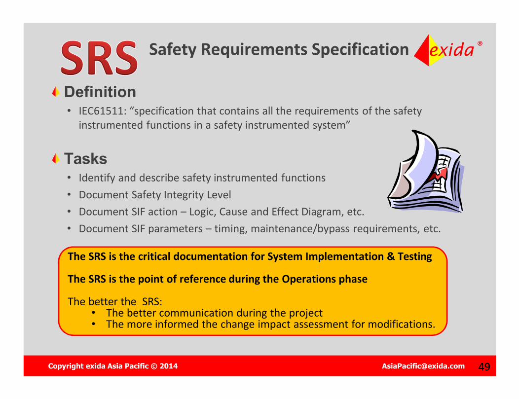
Safety Requirements Specification
The SRS is the critical documentation for System Implementation & Testing
The SRS is the point of reference during the Operations phase
The better the SRS:• The better communication during the project • The more informed the change impact assessment for modifications.
Definition• IEC61511: “specification that contains all the requirements of the safety
instrumented functions in a safety instrumented system”
Tasks• Identify and describe safety instrumented functions• Document Safety Integrity Level• Document SIF action – Logic, Cause and Effect Diagram, etc.• Document SIF parameters – timing, maintenance/bypass requirements, etc.
Copyright exida Asia Pacific © 2014 [email protected] 50
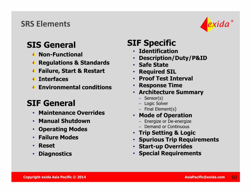
SRS Elements
SIS GeneralNon-FunctionalRegulations & StandardsFailure, Start & RestartInterfacesEnvironmental conditions
SIF General• Maintenance Overrides• Manual Shutdown• Operating Modes• Failure Modes• Reset• Diagnostics
SIF Specific• Identification• Description/Duty/P&ID• Safe State• Required SIL• Proof Test Interval• Response Time• Architecture Summary
– Sensor(s)– Logic Solver– Final Element(s)
• Mode of Operation– Energize or De-energize– Demand or Continuous
• Trip Setting & Logic• Spurious Trip Requirements• Start-up Overrides• Special Requirements
Copyright exida Asia Pacific © 2014 [email protected] 5151
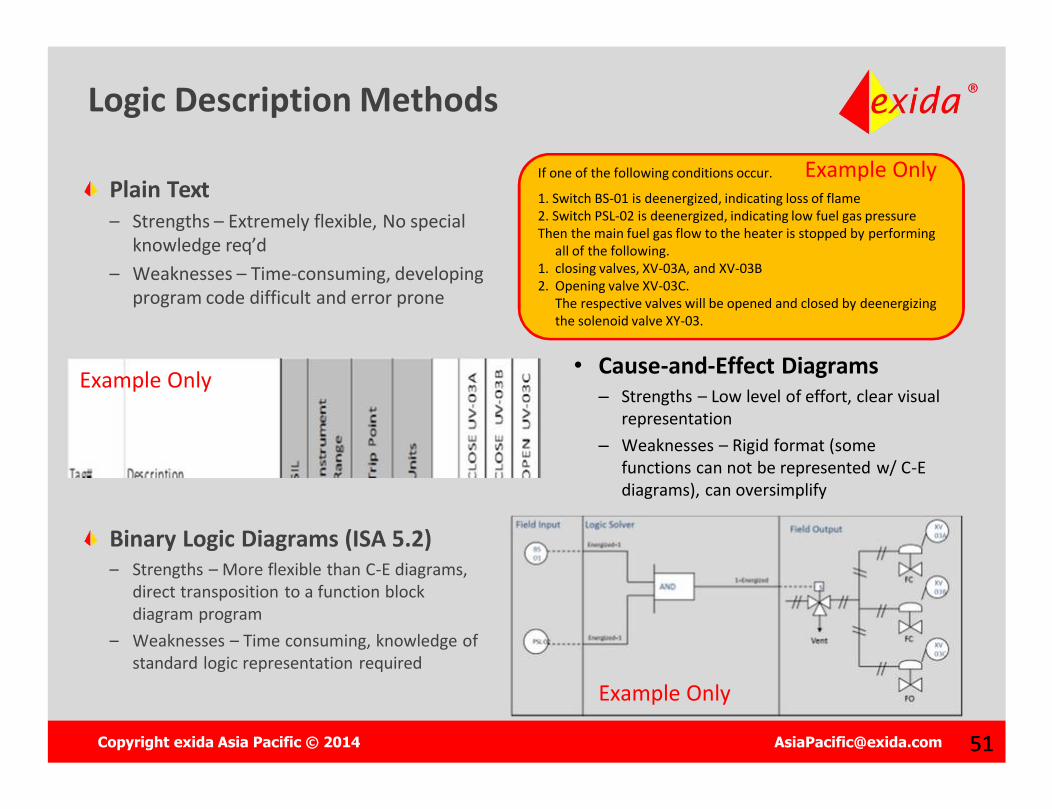
Logic Description Methods
Plain Text– Strengths – Extremely flexible, No special
knowledge req’d– Weaknesses – Time-consuming, developing
program code difficult and error prone
Binary Logic Diagrams (ISA 5.2)– Strengths – More flexible than C-E diagrams,
direct transposition to a function block diagram program
– Weaknesses – Time consuming, knowledge of standard logic representation required
If one of the following conditions occur.
1. Switch BS-01 is deenergized, indicating loss of flame2. Switch PSL-02 is deenergized, indicating low fuel gas pressureThen the main fuel gas flow to the heater is stopped by performing
all of the following.1. closing valves, XV-03A, and XV-03B2. Opening valve XV-03C.
The respective valves will be opened and closed by deenergizingthe solenoid valve XY-03.
Example Only
• Cause-and-Effect Diagrams– Strengths – Low level of effort, clear visual
representation– Weaknesses – Rigid format (some
functions can not be represented w/ C-E diagrams), can oversimplify
Example Only
Example Only

Copyright exida Asia Pacific © 2014 [email protected] 52
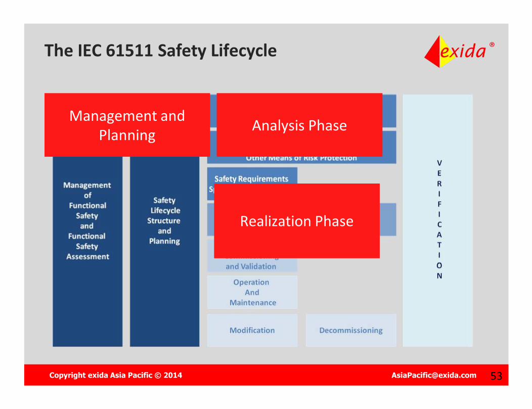
The IEC 61511 Safety Lifecycle
Management and Planning
Management and Planning Analysis PhaseAnalysis Phase
Copyright exida Asia Pacific © 2014 [email protected] 53
The IEC 61511 Safety Lifecycle
Management and Planning
Management and Planning Analysis PhaseAnalysis Phase
Realization PhaseRealization Phase
Copyright exida Asia Pacific © 2014 [email protected] 54
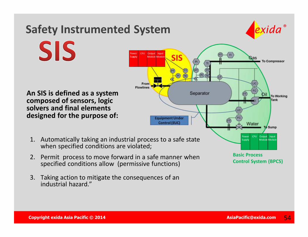
Safety Instrumented System
An SIS is defined as a system composed of sensors, logic solvers and final elements designed for the purpose of:
1. Automatically taking an industrial process to a safe state when specified conditions are violated;
2. Permit process to move forward in a safe manner when specified conditions allow (permissive functions)
3. Taking action to mitigate the consequences of an industrial hazard.”
Equipment Under Control (EUC)
Power Supply
CPU Output Module
InputModule SIS
Power Supply
CPU Output Module
InputModule
Basic Process Control System (BPCS)
Copyright exida Asia Pacific © 2014 [email protected] 5555
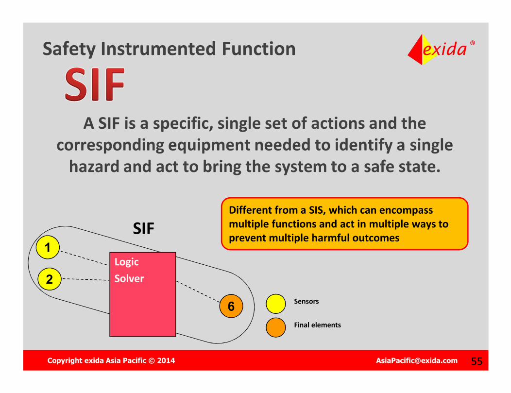
Safety Instrumented Function
A SIF is a specific, single set of actions and the corresponding equipment needed to identify a single
hazard and act to bring the system to a safe state.
Different from a SIS, which can encompass multiple functions and act in multiple ways to prevent multiple harmful outcomes
6
1SIF
LogicSolver
Sensors
Final elements
2
Copyright exida Asia Pacific © 2014 [email protected] 56
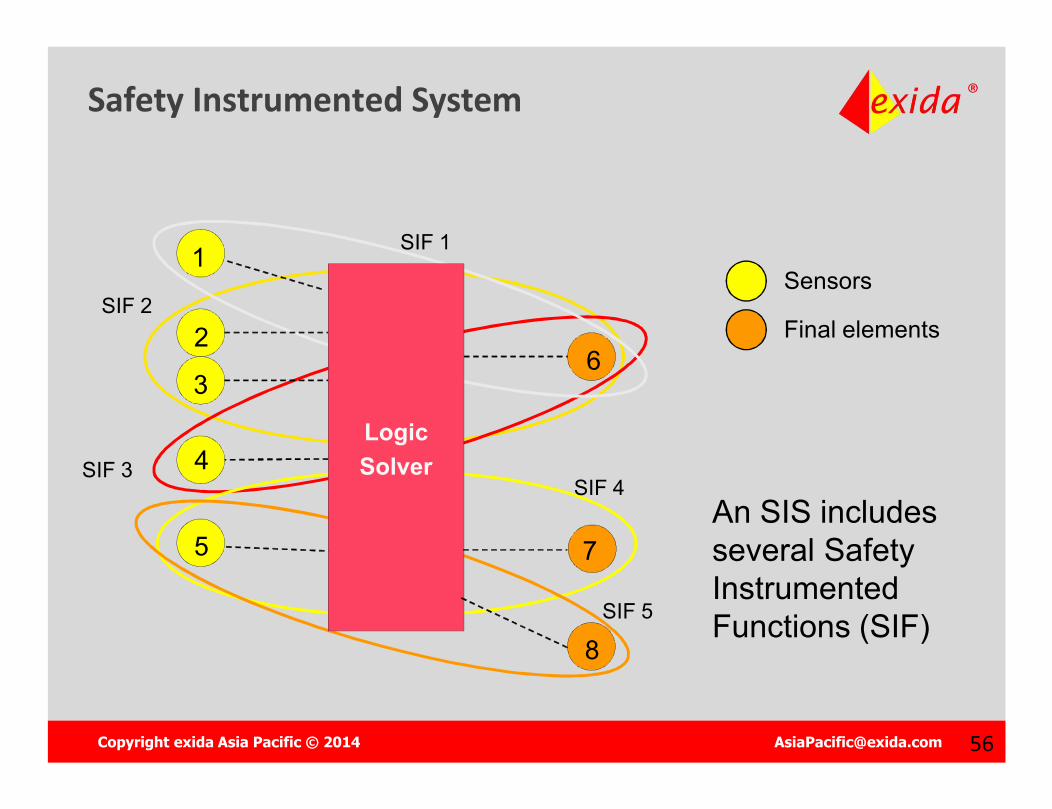
Safety Instrumented System
Sensors
Final elements
An SIS includes several Safety Instrumented Functions (SIF)
SIF 1
SIF 2
SIF 3SIF 4
LogicSolver
1
2
3
4
5
6
7
8SIF 5
Copyright exida Asia Pacific © 2014 [email protected] 57
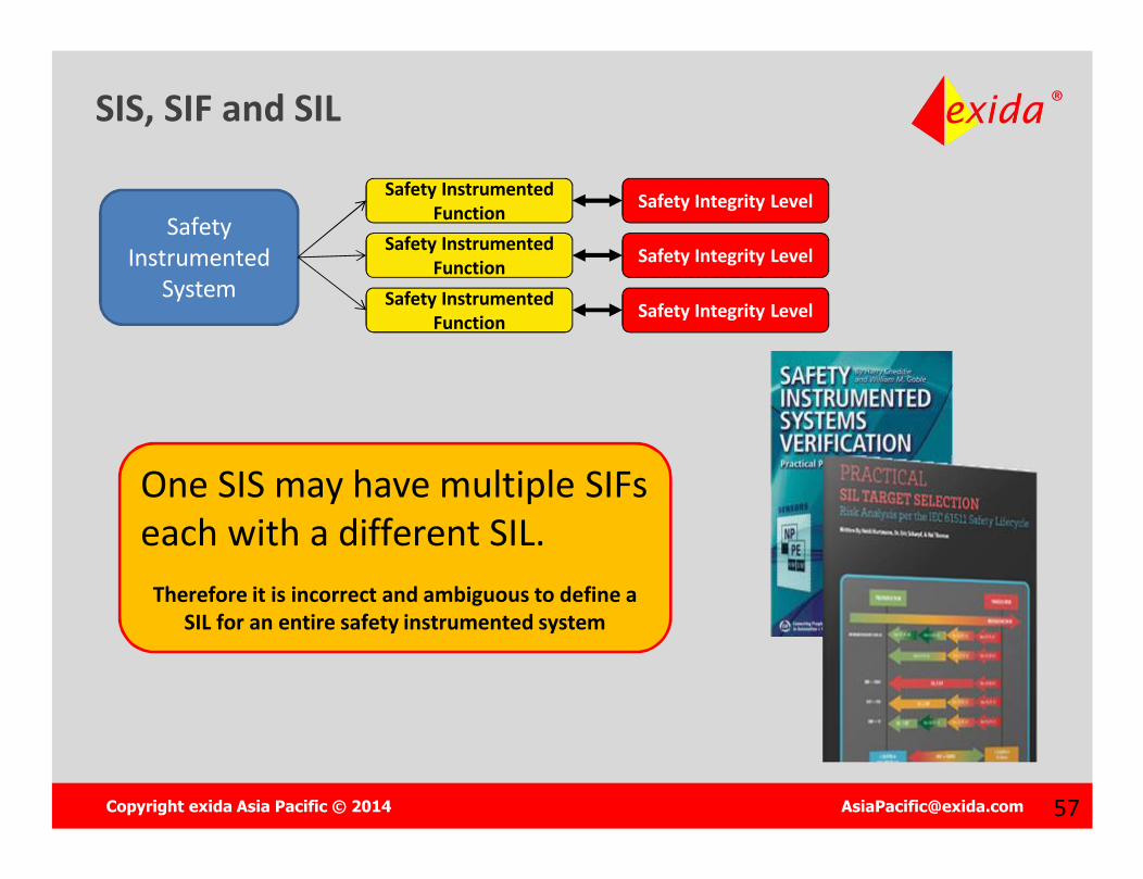
SIS, SIF and SIL
One SIS may have multiple SIFs each with a different SIL.
Therefore it is incorrect and ambiguous to define a SIL for an entire safety instrumented system
Safety Instrumented
System
Safety Instrumented Function
Safety Instrumented Function
Safety Instrumented Function
Safety Integrity Level
Safety Integrity Level
Safety Integrity Level
Copyright exida Asia Pacific © 2014 [email protected] 58
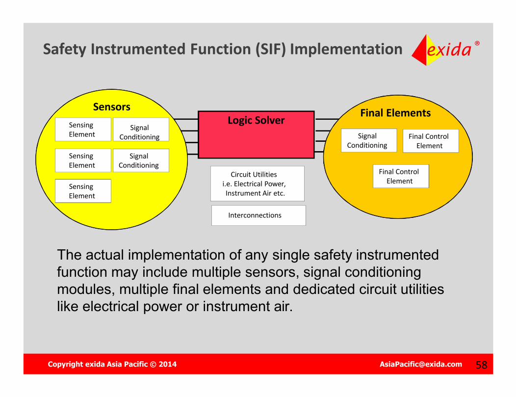
Sensor
Logic Solver
SensingElement
SignalConditioning
SensingElement
SignalConditioning
SensingElement
Final ControlElement
SignalConditioning
Final ControlElement
Circuit Utilitiesi.e. Electrical Power,Instrument Air etc.
The actual implementation of any single safety instrumented function may include multiple sensors, signal conditioning modules, multiple final elements and dedicated circuit utilities like electrical power or instrument air.
Interconnections
Safety Instrumented Function (SIF) Implementation
Sensors Final Elements
Copyright exida Asia Pacific © 2014 [email protected] 5959
RANDOMFailures
RANDOMFailures
IEC 61511 – Protection Against:
SYSTEMATICFailures
SYSTEMATICFailures
Random Failures?Random Failures? Systematic Failures?Systematic Failures?
Copyright exida Asia Pacific © 2014 [email protected] 60
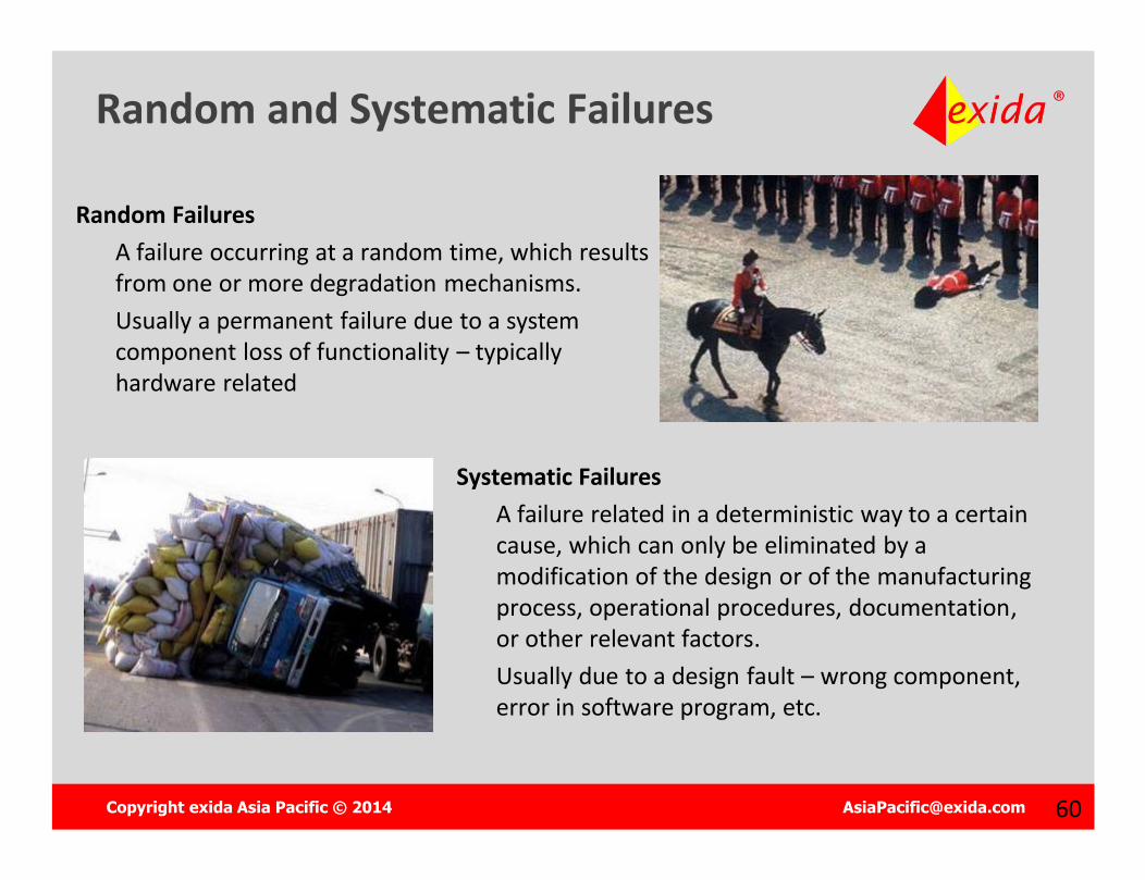
Random and Systematic Failures
Random FailuresA failure occurring at a random time, which results from one or more degradation mechanisms. Usually a permanent failure due to a system component loss of functionality – typically hardware related
Systematic FailuresA failure related in a deterministic way to a certain cause, which can only be eliminated by a modification of the design or of the manufacturing process, operational procedures, documentation, or other relevant factors.Usually due to a design fault – wrong component, error in software program, etc.
Copyright exida Asia Pacific © 2014 [email protected] 6161
RANDOMFailures
RANDOMFailures
IEC 61511 – Protect Against:
SYSTEMATICFailures
SYSTEMATICFailures
HOW?HOW? HOW?HOW?

Copyright exida Asia Pacific © 2014 [email protected] 6262
RANDOMFailures
RANDOMFailures
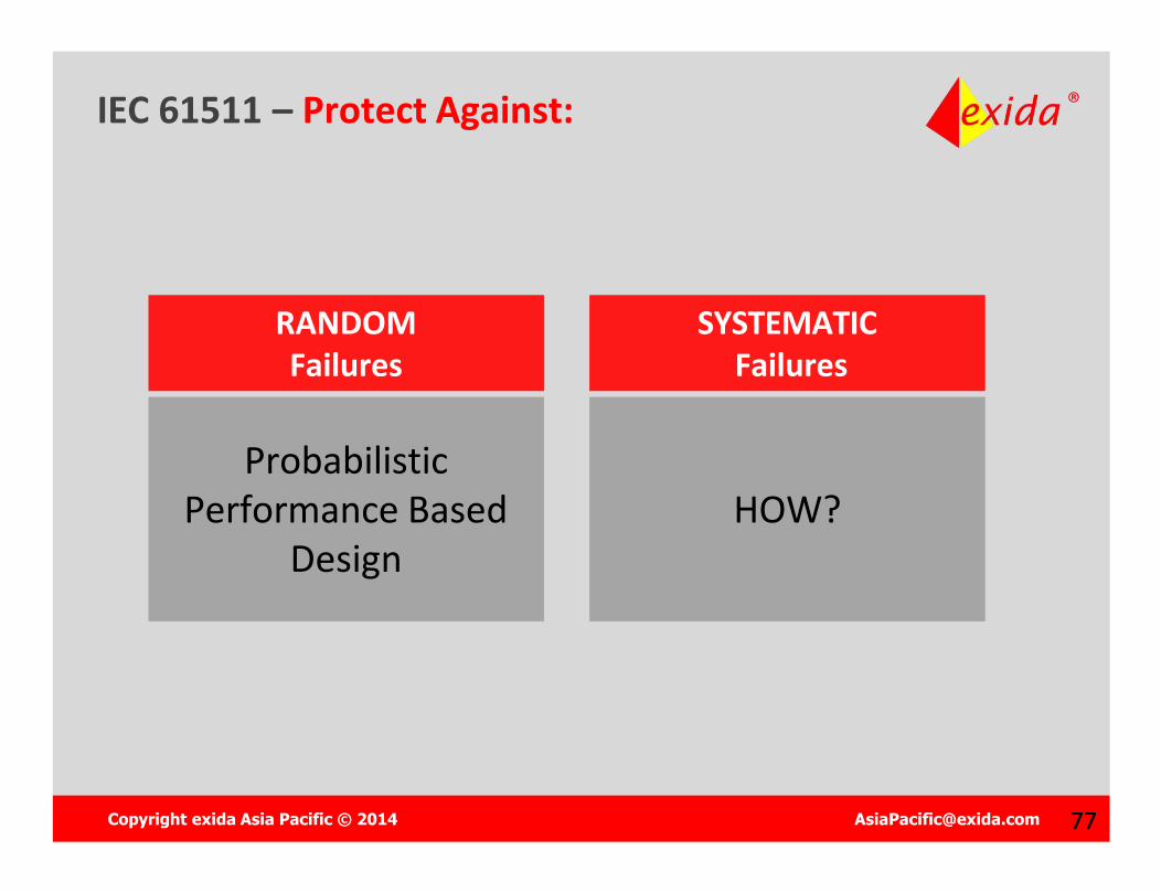
IEC 61511 – Protect Against:
SYSTEMATICFailures
SYSTEMATICFailures
Probabilistic Performance Based
Design
Probabilistic Performance Based
DesignHOW?HOW?
Copyright exida Asia Pacific © 2014 [email protected] 6363
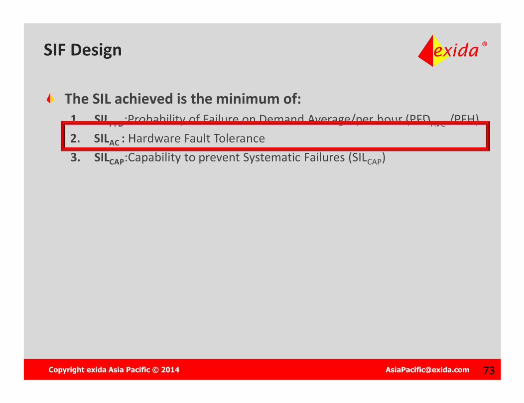
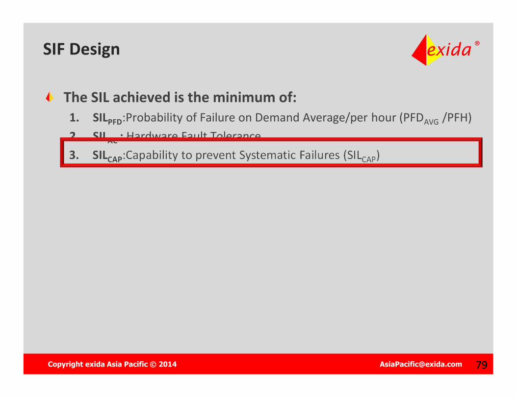
SIF Design
The SIL achieved is the minimum of:1. SILPFD:Probability of Failure on Demand Average/per hour (PFDAVG /PFH)2. SILAC : Hardware Fault Tolerance 3. SILCAP:Capability to prevent Systematic Failures (SILCAP)
Copyright exida Asia Pacific © 2014 [email protected] 6464
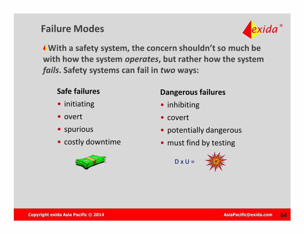
Failure Modes
With a safety system, the concern shouldn’t so much be with how the system operates, but rather how the system fails. Safety systems can fail in two ways:
Safe failures• initiating• overt• spurious• costly downtime
Dangerous failures• inhibiting• covert• potentially dangerous• must find by testing
D x U =
Copyright exida Asia Pacific © 2014 [email protected] 6565
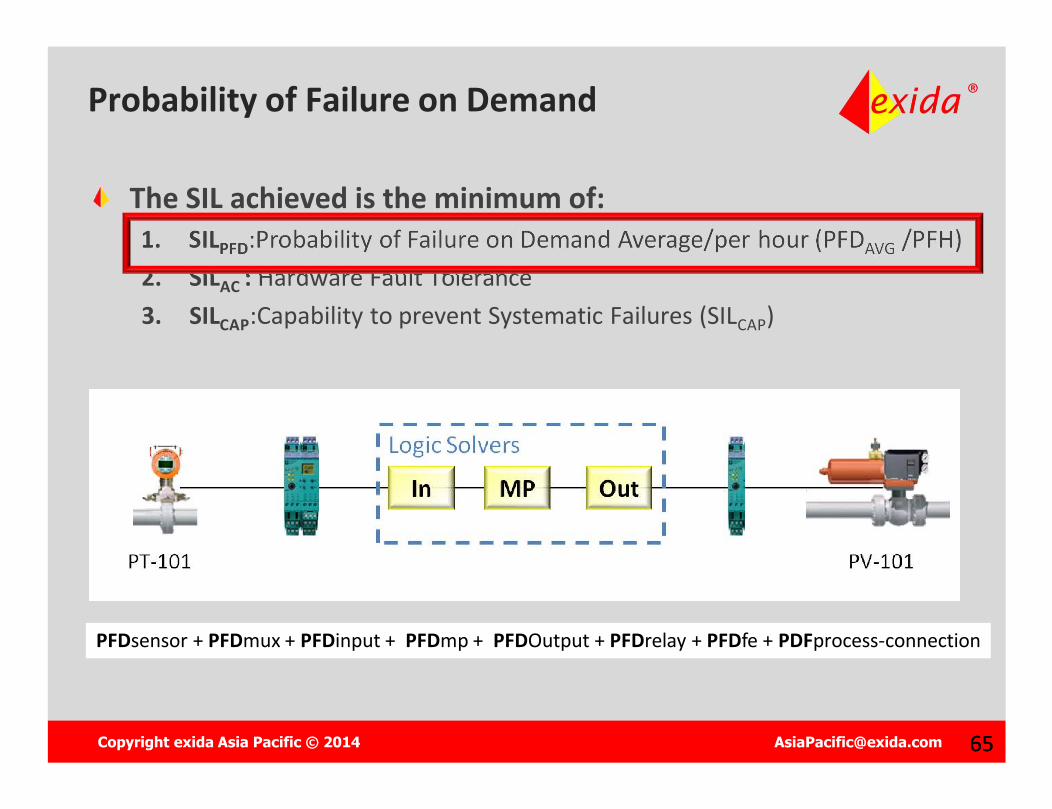
Probability of Failure on Demand
The SIL achieved is the minimum of:1. SILPFD:Probability of Failure on Demand Average/per hour (PFDAVG /PFH)2. SILAC : Hardware Fault Tolerance 3. SILCAP:Capability to prevent Systematic Failures (SILCAP)
PFDsensor + PFDmux + PFDinput + PFDmp + PFDOutput + PFDrelay + PFDfe + PDFprocess-connection
Copyright exida Asia Pacific © 2014 [email protected] 6666
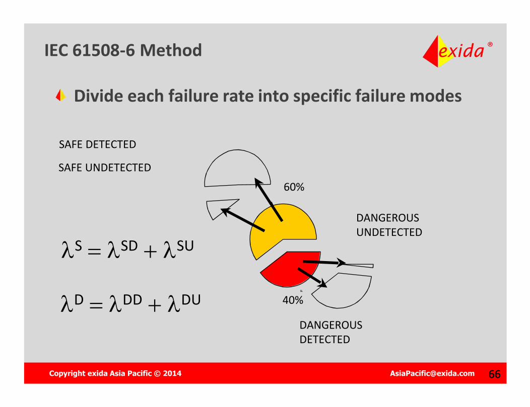
SSDSU
SAFE DETECTED
SAFE UNDETECTED
DANGEROUSUNDETECTED
DANGEROUSDETECTED
DDDDU
60%
40%
Divide each failure rate into specific failure modes
IEC 61508-6 Method
Copyright exida Asia Pacific © 2014 [email protected] 6767
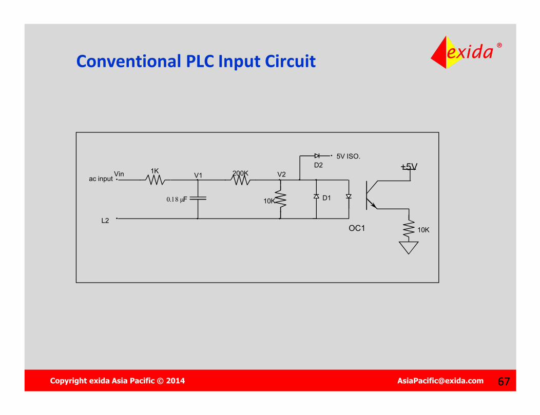
5V ISO.
1K
F
200K
10K
ac input
L2
D1
D2V1 V2Vin
+5V
OC1 10K
Conventional PLC Input Circuit
Copyright exida Asia Pacific © 2014 [email protected] 6868
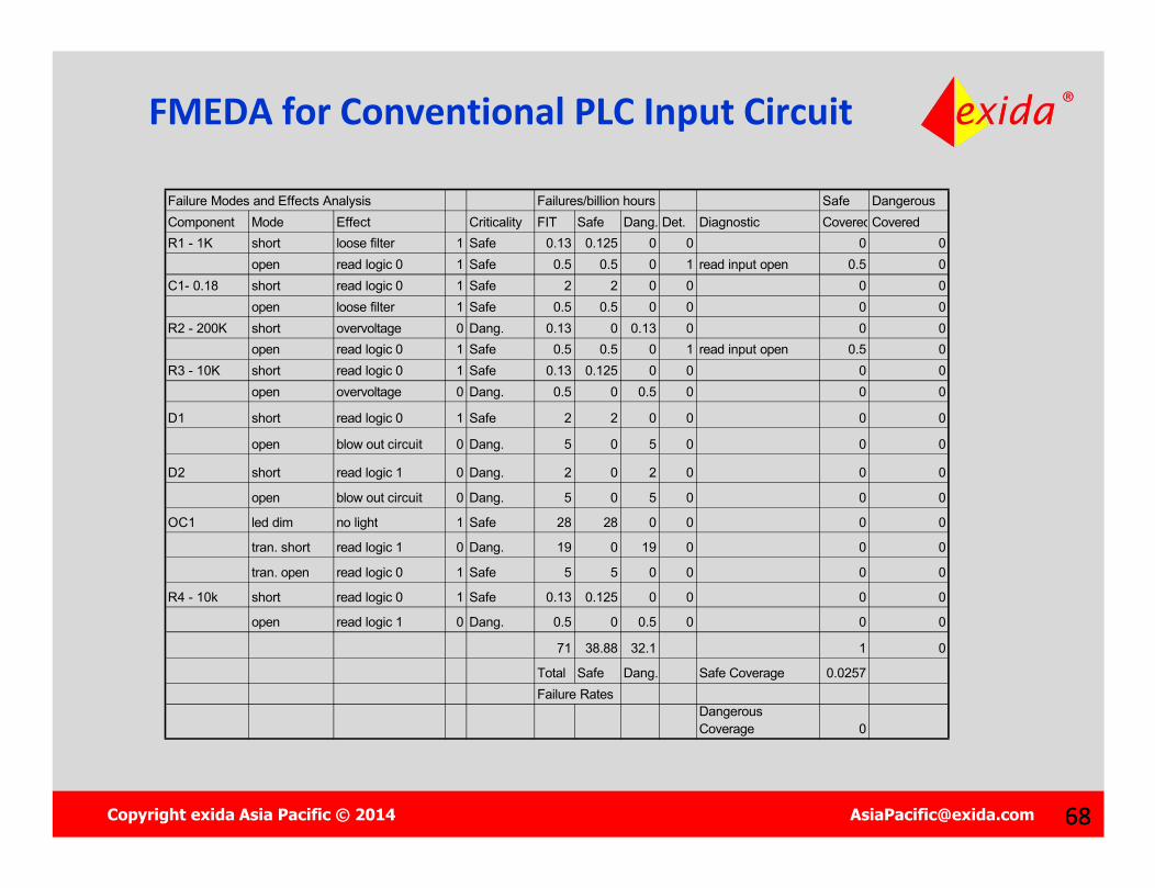
Failure Modes and Effects Analysis Failures/billion hours Safe Dangerous Component Mode Effect Criticality FIT Safe Dang. Det. Diagnostic Covered FITCoveredR1 - 1K short loose filter 1 Safe 0.13 0.125 0 0 0 0
open read logic 0 1 Safe 0.5 0.5 0 1 read input open 0.5 0C1- 0.18 short read logic 0 1 Safe 2 2 0 0 0 0
open loose filter 1 Safe 0.5 0.5 0 0 0 0R2 - 200K short overvoltage 0 Dang. 0.13 0 0.13 0 0 0
open read logic 0 1 Safe 0.5 0.5 0 1 read input open 0.5 0R3 - 10K short read logic 0 1 Safe 0.13 0.125 0 0 0 0
open overvoltage 0 Dang. 0.5 0 0.5 0 0 0
D1 short read logic 0 1 Safe 2 2 0 0 0 0
open blow out circuit 0 Dang. 5 0 5 0 0 0
D2 short read logic 1 0 Dang. 2 0 2 0 0 0
open blow out circuit 0 Dang. 5 0 5 0 0 0
OC1 led dim no light 1 Safe 28 28 0 0 0 0
tran. short read logic 1 0 Dang. 19 0 19 0 0 0
tran. open read logic 0 1 Safe 5 5 0 0 0 0
R4 - 10k short read logic 0 1 Safe 0.13 0.125 0 0 0 0
open read logic 1 0 Dang. 0.5 0 0.5 0 0 0
71 38.88 32.1 1 0
Total Safe Dang. Safe Coverage 0.0257Failure Rates
Dangerous Coverage 0
FMEDA for Conventional PLC Input Circuit

Copyright exida Asia Pacific © 2014 [email protected] 7070
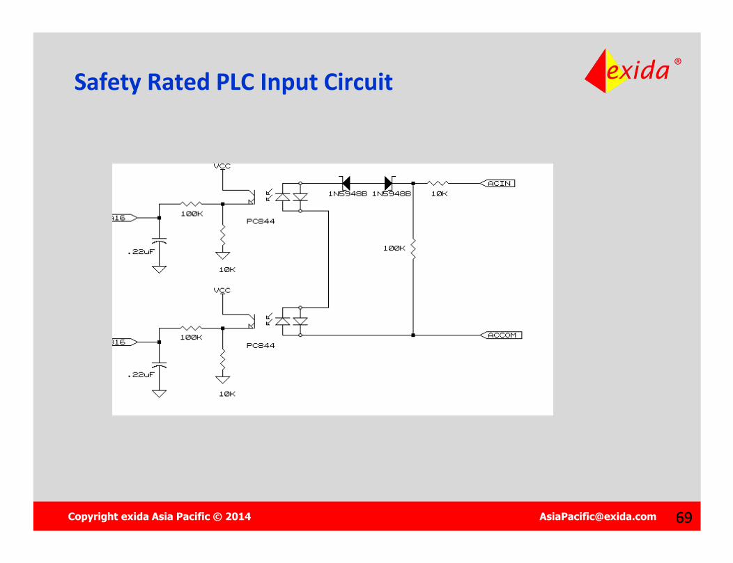
FMEDA for Safety Rated Input CircuitF ailu re M od es an d E f fec ts A n alys is F ailu res /b illion hou rs S afe D an g erous C om p on ent M od e E ffec t C riticality F IT S afe D ang . D et. D iagn os tic C overed F ITC overedR 1 - 1 0 K sh ort T hresh old s hif t 1 S afe 0 .13 0 .1 25 0 0 0 0
op en op en c ircu it 1 S afe 0 .5 0 .5 0 1 loose in pu t p uls e 0 .5 0R 2 - 1 0 0K sh ort sh ort in p ut 1 S afe 0 .13 0 .1 25 0 1 loose in pu t p uls e 0.12 5 0
op en T hresh old s hif t 1 S afe 0 .5 0 .5 0 0 0 0
D 1 sh ort overvoltag e 1 S afe 2 2 0 1 loose in pu t p uls e 2 0op en op en c ircu it 1 S afe 5 5 0 1 loose in pu t p uls e 5 0
D 2 sh ort overvoltag e 1 S afe 2 2 0 1 loose in pu t p uls e 2 0op en op en c ircu it 1 S afe 5 5 0 1 loose in pu t p uls e 5 0
O C 1 led d im n o lig h t 1 S afe 28 2 8 0 1 C om p . m is m atch 2 8 0
tran. sh ort read log ic 1 0 D an g . 10 0 10 1 C om p . m is m atch 0 1 0
tran. op en read log ic 0 1 S afe 6 6 0 1 C om p . m is m atch 6 0
O C 2 led d im n o lig h t 1 S afe 28 2 8 0 1 C om p . m is m atch 2 8 0
tran. sh ort read log ic 1 0 D an g . 10 0 10 1 C om p . m is m atch 0 1 0
tran. op en read log ic 0 1 S afe 6 6 0 1 C om p . m is m atch 6 0R 3 - 1 0 0K sh ort loose filter 1 S afe 0 .13 0 .1 25 0 0 0 0
op en in pu t f loat h igh 0 D an g . 0 .5 0 0 .5 1 C om p . m is m atch 0 0 .5R 4 - 1 0 K sh ort read log ic 0 1 S afe 0 .13 0 .1 25 0 1 C om p . m is m atch 0.12 5 0
op en read log ic 1 0 D an g . 0 .5 0 0 .5 1 C om p . m is m atch 0 0 .5R 5 - 1 0 0K sh ort loose filter 1 S afe 0 .13 0 .1 25 0 0 0 0
op en in pu t f loat h igh 0 D an g . 0 .5 0 0 .5 1 C om p . m is m atch 0 0 .5R 6 - 1 0 K sh ort read log ic 0 1 S afe 0 .13 0 .1 25 0 1 C om p . m is m atch 0.12 5 0
op en read log ic 1 0 D an g . 0 .5 0 0 .5 1 C om p . m is m atch 0 0 .5C 1 sh ort read log ic 0 1 S afe 2 2 0 1 C om p . m is m atch 2 0
op en loose filter 1 S afe 0 .5 0 .5 0 0 0 0C 2 sh ort read log ic 0 1 S afe 2 2 0 1 C om p . m is m atch 2 0
op en loose filter 1 S afe 0 .5 0 .5 0 0 0 01 11 8 8.75 22 8 6.87 5 2 2
T otal S afe D ang . S afe C overag e 0 .9 78 9F ailu re R ates
D an gerou s C overage 1
Copyright exida Asia Pacific © 2014 [email protected] 7171
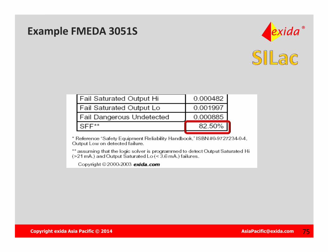
What is…?
Safe Failure Fraction: A measurement of the likelihood of getting a dangerous failure that is NOT detected by automatic self diagnositcs
.
NOTE: Definitions refer to single channel architectures.

Copyright exida Asia Pacific © 2014 [email protected] 72
IEC 61508 Safe Failure Fraction (SFF)
SFF = SD + SU + DD
SD + SU + DD + DU
= 1 - DU
Total
Copyright exida Asia Pacific © 2014 [email protected] 7373
SIF Design
The SIL achieved is the minimum of:1. SILPFD:Probability of Failure on Demand Average/per hour (PFDAVG /PFH)2. SILAC : Hardware Fault Tolerance 3. SILCAP:Capability to prevent Systematic Failures (SILCAP)
Copyright exida Asia Pacific © 2014 [email protected] 74
Architectural Constraints
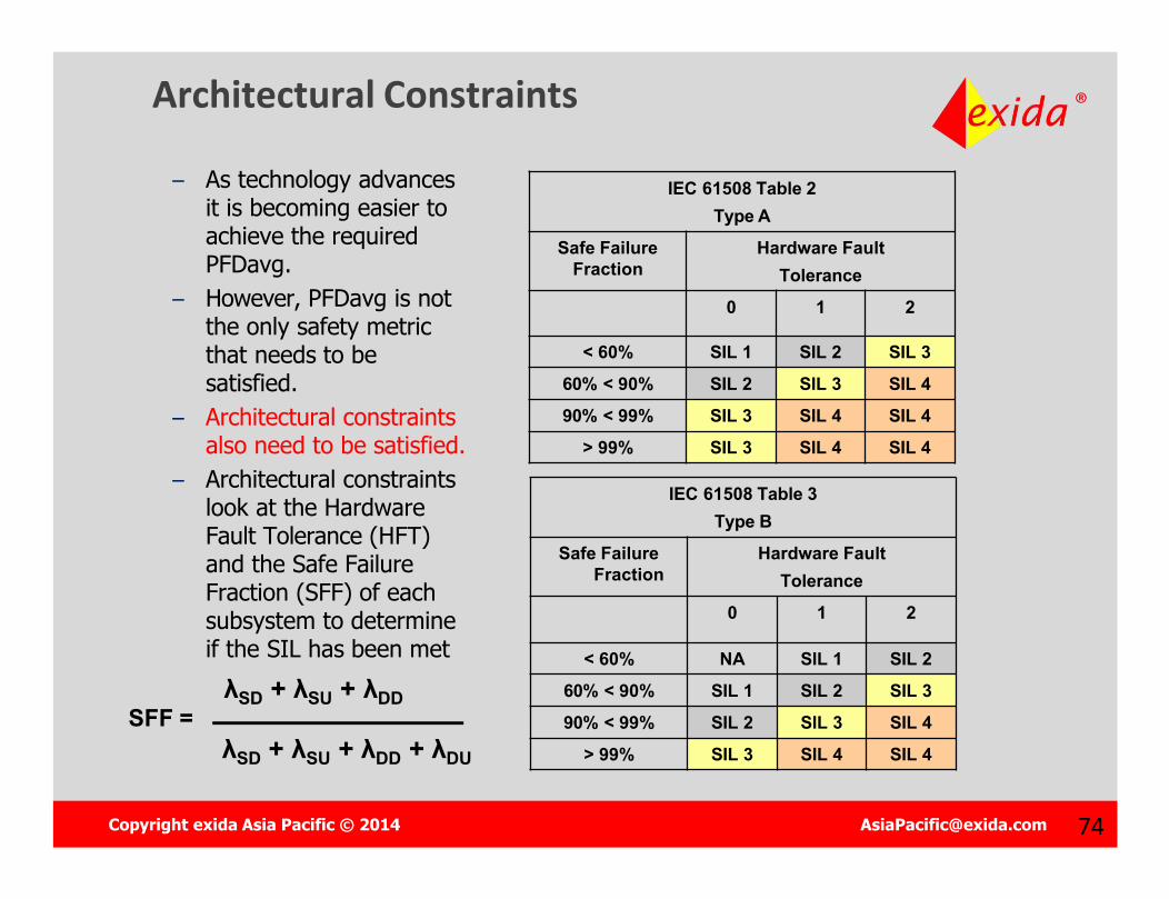
– As technology advances it is becoming easier to achieve the required PFDavg.
– However, PFDavg is not the only safety metric that needs to be satisfied.
– Architectural constraints also need to be satisfied.
– Architectural constraints look at the Hardware Fault Tolerance (HFT) and the Safe Failure Fraction (SFF) of each subsystem to determine if the SIL has been met
IEC 61508 Table 3Type B
Safe Failure Fraction
Hardware Fault Tolerance
0 1 2
< 60% NA SIL 1 SIL 2
60% < 90% SIL 1 SIL 2 SIL 3
90% < 99% SIL 2 SIL 3 SIL 4
> 99% SIL 3 SIL 4 SIL 4
IEC 61508 Table 2Type A
Safe Failure Fraction
Hardware Fault Tolerance
0 1 2
< 60% SIL 1 SIL 2 SIL 3
60% < 90% SIL 2 SIL 3 SIL 4
90% < 99% SIL 3 SIL 4 SIL 4
> 99% SIL 3 SIL 4 SIL 4
SFF =λSD + λSU + λDD
λSD + λSU + λDD + λDU
Copyright exida Asia Pacific © 2014 [email protected] 7676
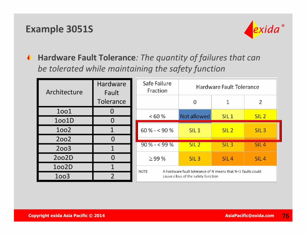
Example 3051S
Hardware Fault Tolerance: The quantity of failures that can be tolerated while maintaining the safety function
ArchitectureHardware
FaultTolerance
1oo1 01oo1D 01oo2 12oo2 02oo3 1
2oo2D 01oo2D 11oo3 2
Copyright exida Asia Pacific © 2014 [email protected] 7777
RANDOMFailures
RANDOMFailures
IEC 61511 – Protect Against:
SYSTEMATICFailures
SYSTEMATICFailures
Probabilistic Performance Based
Design
Probabilistic Performance Based
DesignHOW?HOW?

Copyright exida Asia Pacific © 2014 [email protected] 7878
RANDOMFailures
RANDOMFailures
IEC 61511 – Protect Against:
SYSTEMATICFailures
SYSTEMATICFailures
Probabilistic Performance Based
Design
Probabilistic Performance Based
Design
Detailed Engineering Process
Detailed Engineering Process
Copyright exida Asia Pacific © 2014 [email protected] 7979
SIF Design
The SIL achieved is the minimum of:1. SILPFD:Probability of Failure on Demand Average/per hour (PFDAVG /PFH)2. SILAC : Hardware Fault Tolerance 3. SILCAP:Capability to prevent Systematic Failures (SILCAP)
Copyright exida Asia Pacific © 2014 [email protected] 8080
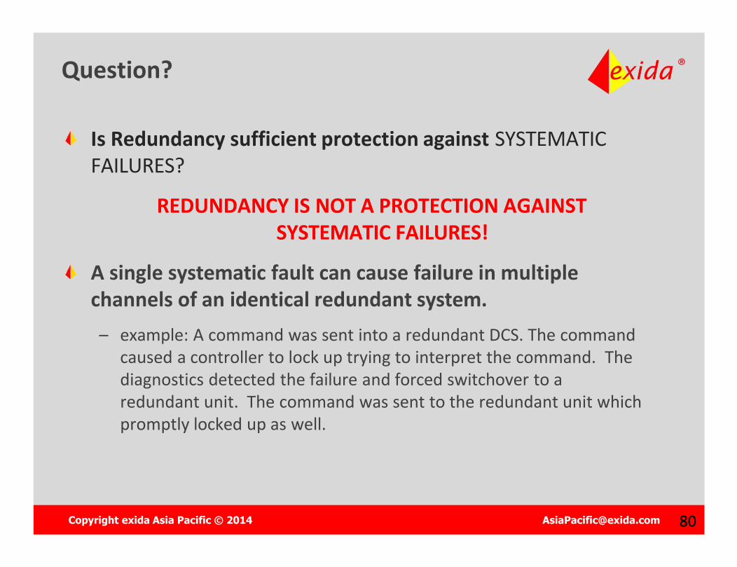
Question?
Is Redundancy sufficient protection against SYSTEMATIC FAILURES?
REDUNDANCY IS NOT A PROTECTION AGAINST SYSTEMATIC FAILURES!
A single systematic fault can cause failure in multiple channels of an identical redundant system. – example: A command was sent into a redundant DCS. The command
caused a controller to lock up trying to interpret the command. The diagnostics detected the failure and forced switchover to a redundant unit. The command was sent to the redundant unit which promptly locked up as well.
Copyright exida Asia Pacific © 2014 [email protected] 81
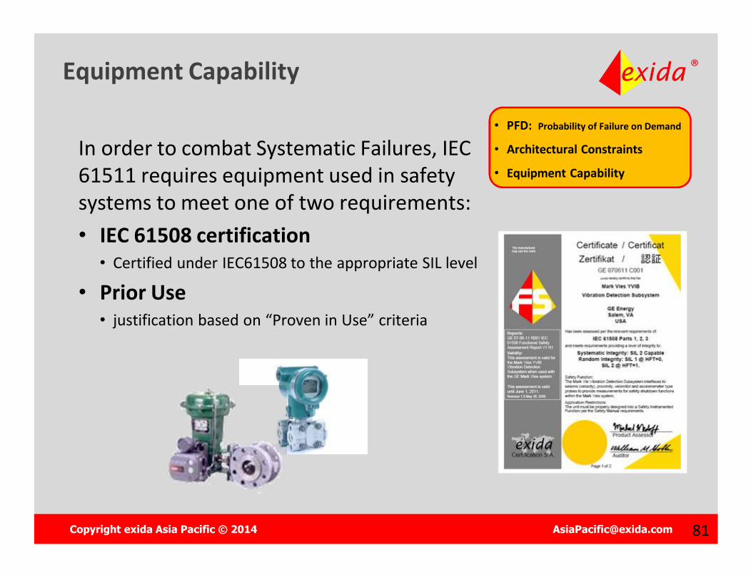
Equipment Capability
• PFD: Probability of Failure on Demand
• Architectural Constraints
• Equipment CapabilityIn order to combat Systematic Failures, IEC 61511 requires equipment used in safety systems to meet one of two requirements:• IEC 61508 certification
• Certified under IEC61508 to the appropriate SIL level
• Prior Use• justification based on “Proven in Use” criteria

Copyright exida Asia Pacific © 2014 [email protected] 8282
Prior Use
“Prior use” generally means:
• Documented, successful experience (no dangerous failures)
• A particular version of a particular instrument
• Similar conditions of use
Functionality/Application Environment
• We do not have the failure data!• I do not want to take responsibility for equipment justification!• We do not take the time to record all instrument failures! • This is a new instrument!• I cannot justify PRIOR USE!
Copyright exida Asia Pacific © 2014 [email protected] 8383
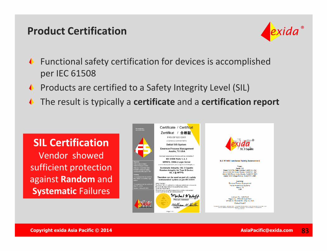
Product Certification
Functional safety certification for devices is accomplished per IEC 61508Products are certified to a Safety Integrity Level (SIL)The result is typically a certificate and a certification report
SIL Certification Vendor showed
sufficient protection against Random and Systematic Failures
SIL Certification Vendor showed
sufficient protection against Random and Systematic Failures
Copyright exida Asia Pacific © 2014 [email protected] 84
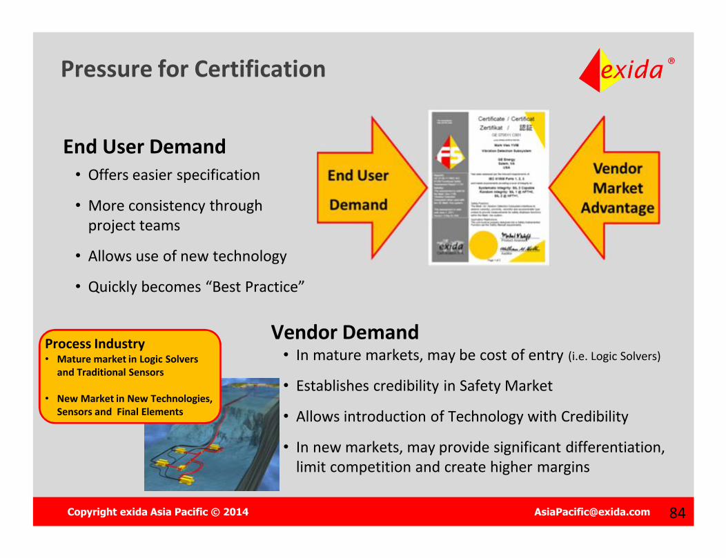
Pressure for Certification
End User Demand• Offers easier specification
• More consistency through project teams
• Allows use of new technology
• Quickly becomes “Best Practice”
Vendor Demand• In mature markets, may be cost of entry (i.e. Logic Solvers)
• Establishes credibility in Safety Market
• Allows introduction of Technology with Credibility
• In new markets, may provide significant differentiation, limit competition and create higher margins
Process Industry• Mature market in Logic Solvers
and Traditional Sensors
• New Market in New Technologies, Sensors and Final Elements

Copyright exida Asia Pacific © 2014 [email protected] 8585
Market Support
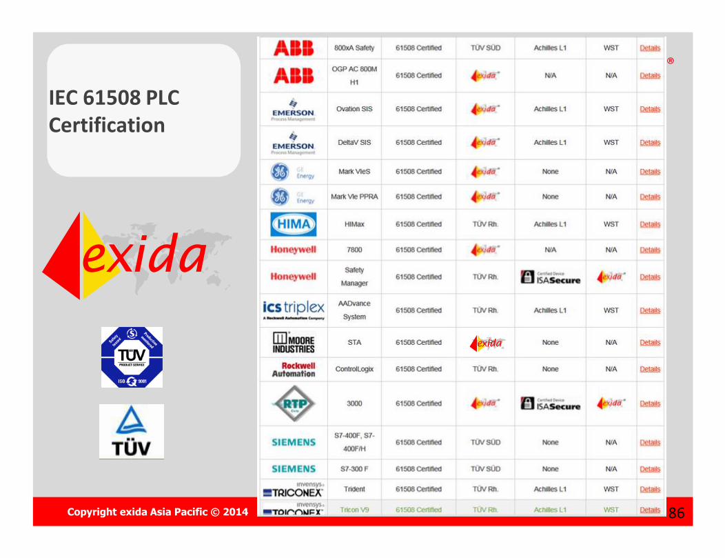
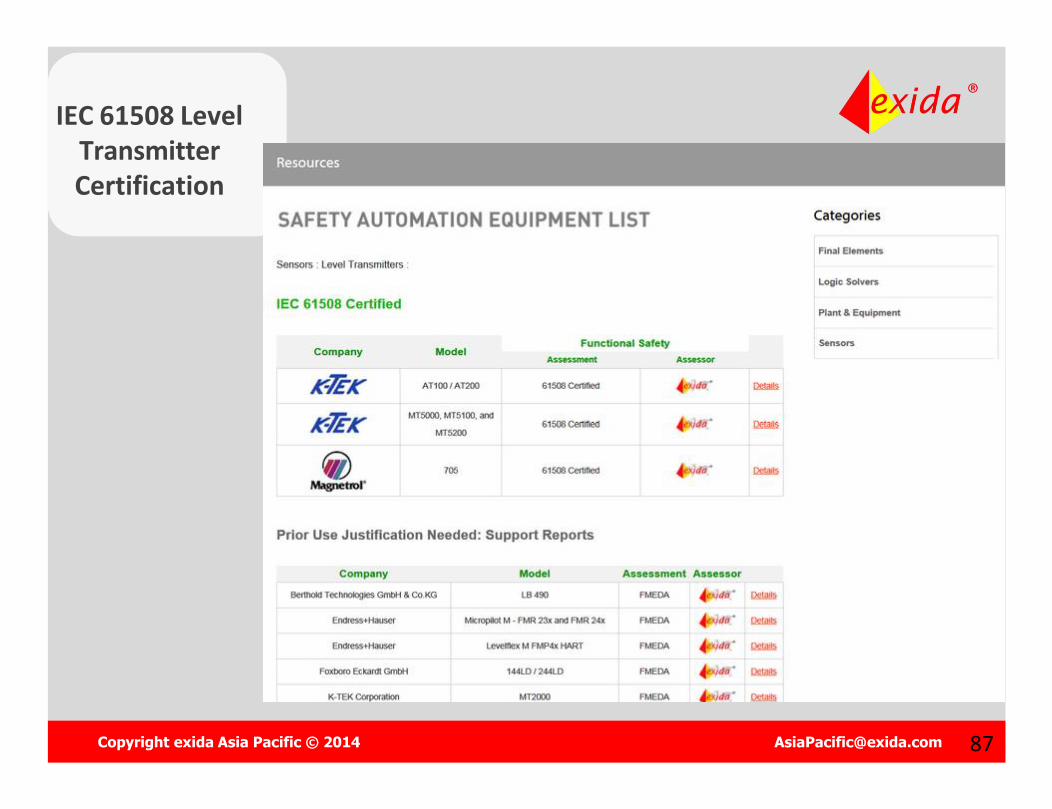
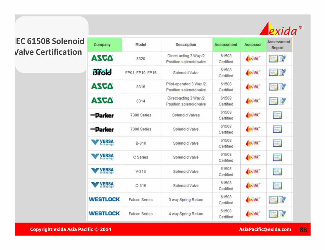
The exida web site also has a list of process industry instrumentation equipment with IEC 61508 certification. With several thousand unique visitors per month, this list has become the most popular global “purchase qualification list” for many buyers.
Copyright exida Asia Pacific © 2014 [email protected] 89
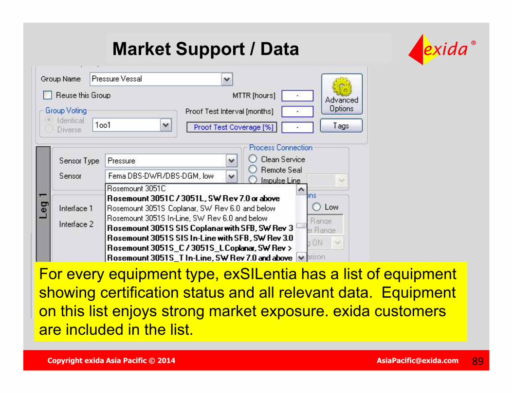
Market Support / Data
For every equipment type, exSILentia has a list of equipment showing certification status and all relevant data. Equipment on this list enjoys strong market exposure. exida customers are included in the list.

Copyright exida Asia Pacific © 2014 [email protected] 9090
Example…
The SIL achieved is the minimum of:1. SILPFD: SIL22. SILAC : SIL13. SILCAP: SIL3
The SIL level for this Safety Instrumented
Function (SIF) is:???
Copyright exida Asia Pacific © 2014 [email protected] 9191
Example
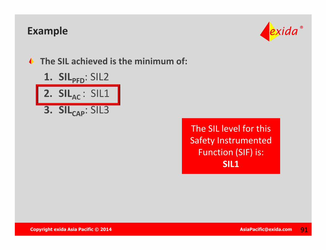
The SIL achieved is the minimum of:1. SILPFD: SIL22. SILAC : SIL13. SILCAP: SIL3
The SIL level for this Safety Instrumented
Function (SIF) is:SIL1

Copyright exida Asia Pacific © 2014 [email protected] 92
Objective Choose the right equipment for the purpose. All criteria used for
process control still applies.
Tasks Choose equipment - IEC 61508 certification or Prior Use
Justification (IEC-61511) Obtain reliability and safety data for the equipment Obtain Safety Manual for any safety certified equipment
Select Technology
Sensor Sub-System Logic Solver Sub-System Final Element Sub-System
Copyright exida Asia Pacific © 2014 [email protected] 9393
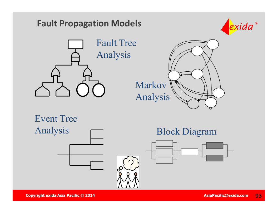
Fault Propagation Models
Fault Tree Analysis
Event Tree Analysis
DU
Markov Analysis
Block Diagram
Copyright exida Asia Pacific © 2014 [email protected] 9494
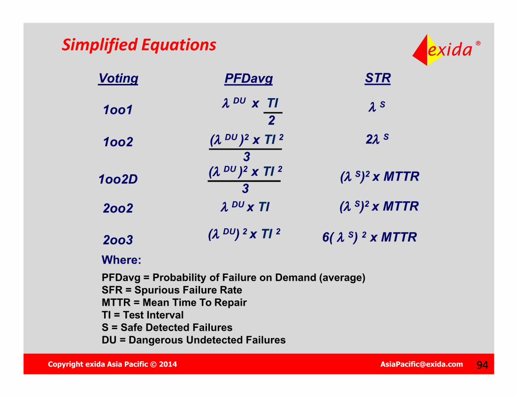
Simplified Equations
Voting
1oo1
1oo2
2oo2
2oo3
1oo2D
STR
S
2 S
6( S) 2 x MTTR
( S)2 x MTTR
PFDavg
Where:PFDavg = Probability of Failure on Demand (average)SFR = Spurious Failure RateMTTR = Mean Time To RepairTI = Test IntervalS = Safe Detected FailuresDU = Dangerous Undetected Failures
( DU )2 x TI 2
3( DU )2 x TI 2
3( S)2 x MTTR DU x TI
( DU) 2 x TI 2
DU x TI2
Copyright exida Asia Pacific © 2014 [email protected] 9595
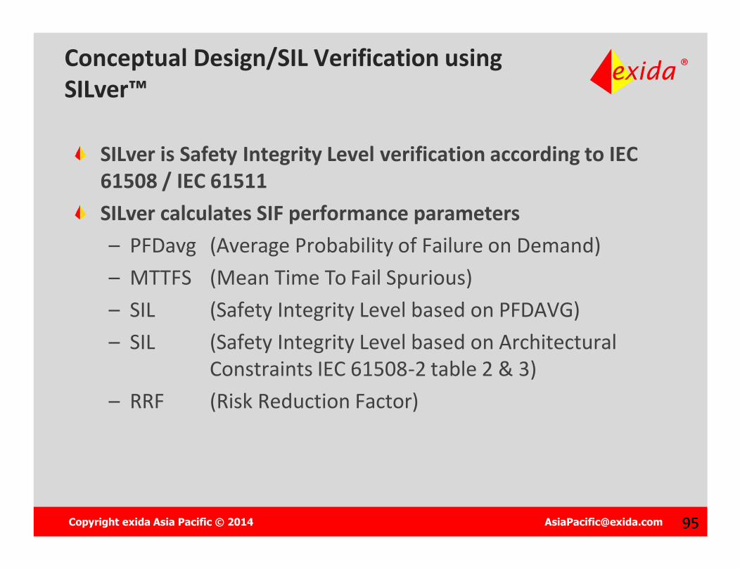
Conceptual Design/SIL Verification usingSILver™
SILver is Safety Integrity Level verification according to IEC 61508 / IEC 61511SILver calculates SIF performance parameters– PFDavg (Average Probability of Failure on Demand)– MTTFS (Mean Time To Fail Spurious)– SIL (Safety Integrity Level based on PFDAVG)– SIL (Safety Integrity Level based on Architectural
Constraints IEC 61508-2 table 2 & 3)– RRF (Risk Reduction Factor)
Copyright exida Asia Pacific © 2014 [email protected] 9696
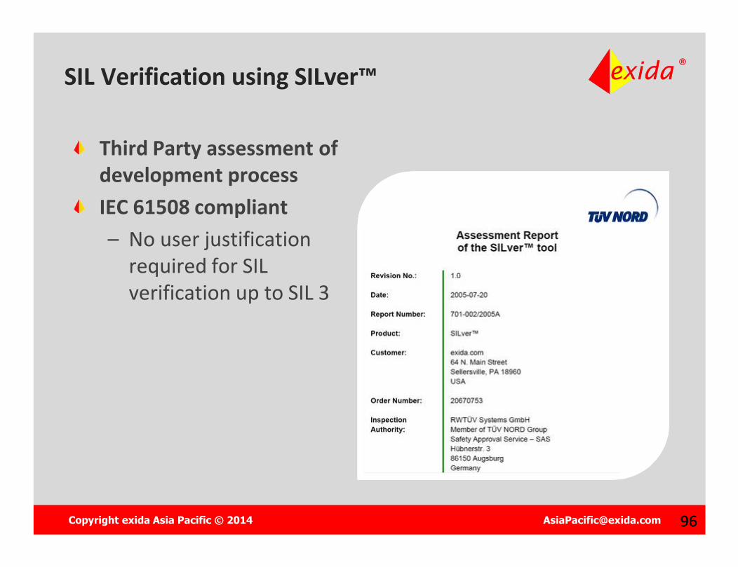
Third Party assessment of development processIEC 61508 compliant– No user justification
required for SIL verification up to SIL 3
SIL Verification using SILver™

Copyright exida Asia Pacific © 2014 [email protected] 98
The IEC 61511 Safety Lifecycle
Management and Planning
Management and Planning Analysis PhaseAnalysis Phase
Realization PhaseRealization Phase

Copyright exida Asia Pacific © 2014 [email protected] 99
The IEC 61511 Safety Lifecycle
Management and Planning
Management and Planning Analysis PhaseAnalysis Phase
Realization PhaseRealization Phase
Operate and MaintainOperate and Maintain

Copyright exida Asia Pacific © 2014 [email protected] 100100
What is…?
Proof Testing: A manually initiated test designed to detect failure of any part of a SIF. Different proof test procedures can have different levels of
effectiveness.
No practical proof test will detect all
failures
No practical proof test will detect all
failures
Copyright exida Asia Pacific © 2014 [email protected] 101101
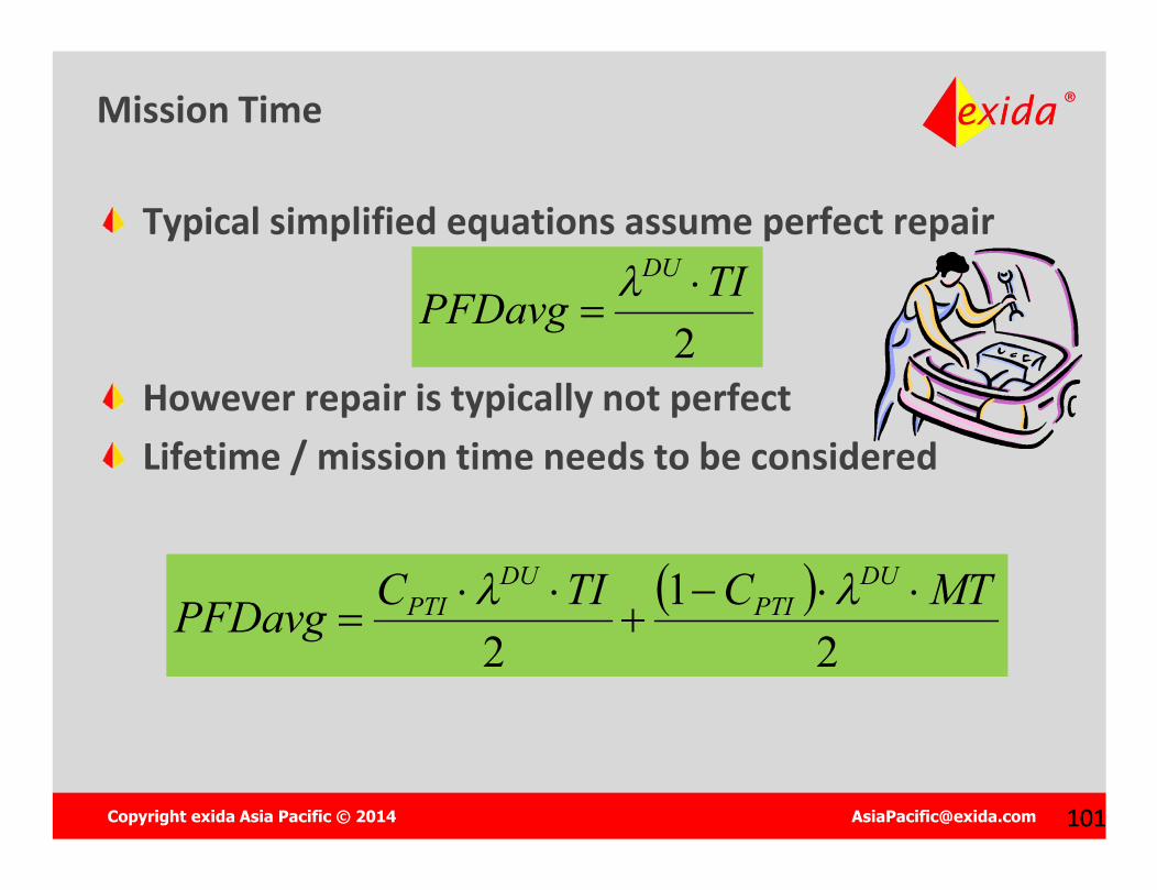
Mission Time
Typical simplified equations assume perfect repair
However repair is typically not perfectLifetime / mission time needs to be considered
2TIPFDavg
DU
2
12
MTCTICPFDavgDU
PTIDU
PTI
Copyright exida Asia Pacific © 2014 [email protected] 102
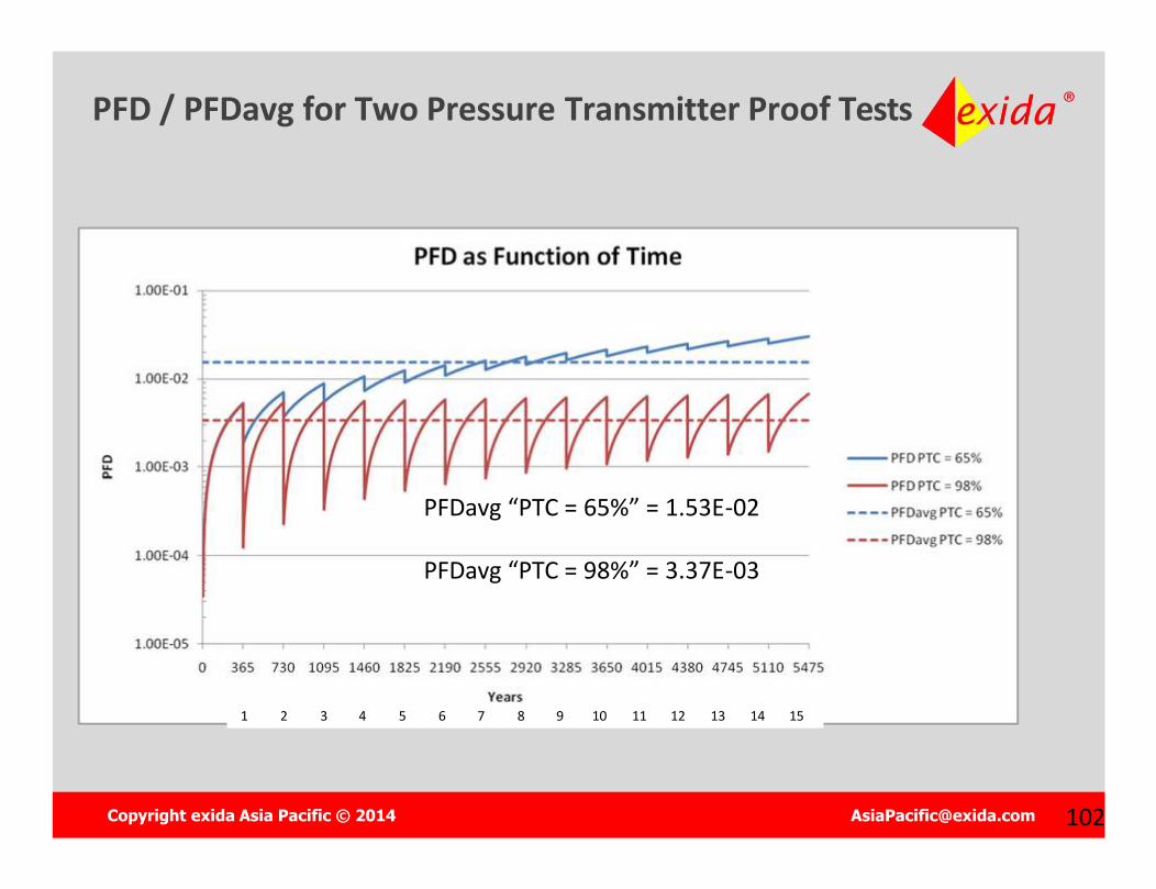
PFD / PFDavg for Two Pressure Transmitter Proof Tests
1 2 3 4 5 6 7 8 9 10 11 12 13 14 15
PFDavg “PTC = 65%” = 1.53E-02
PFDavg “PTC = 98%” = 3.37E-03
Copyright exida Asia Pacific © 2014 [email protected] 103
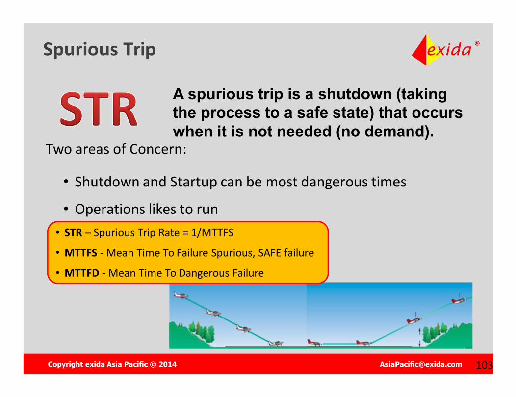
Spurious Trip
A spurious trip is a shutdown (taking the process to a safe state) that occurs when it is not needed (no demand).
• STR – Spurious Trip Rate = 1/MTTFS
• MTTFS - Mean Time To Failure Spurious, SAFE failure
• MTTFD - Mean Time To Dangerous Failure
Two areas of Concern:
• Shutdown and Startup can be most dangerous times
• Operations likes to run

Copyright exida Asia Pacific © 2014 [email protected] 104
The IEC 61511 Safety Lifecycle
Management and Planning
Management and Planning Analysis PhaseAnalysis Phase
Realization PhaseRealization Phase
Operate and MaintainOperate and Maintain
Copyright exida Asia Pacific © 2014 [email protected] 105
REGULATIONS, STANDARDS AND BEST PRACTICES
Industrial Control Systems Cybersecurity
Copyright exida Asia Pacific © 2014 [email protected] 106106
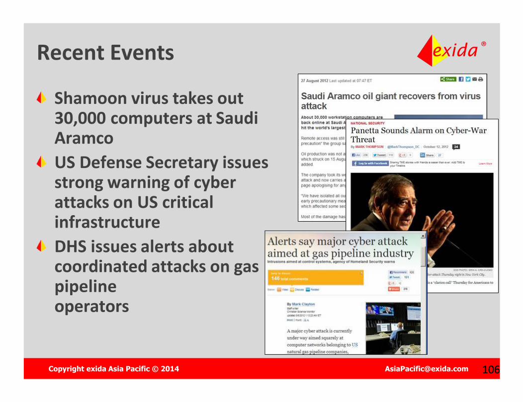
Recent Events
Shamoon virus takes out 30,000 computers at Saudi AramcoUS Defense Secretary issues strong warning of cyber attacks on US critical infrastructureDHS issues alerts about coordinated attacks on gas pipeline operators
Copyright exida Asia Pacific © 2014 [email protected] 107
Control systems operate industrial plant equipment and critical processesTampering with these systems can lead to:– Death, Injury, Sickness– Environmental releases– Equipment Damage– Production loss / service interruption– Off-spec / Dangerous product– Loss of Trade Secrets
Control system security is about preventing intentional or unintentional Interference with the proper operation of plant
Control System Cyber Security

Copyright exida Asia Pacific © 2014 [email protected] 108
Now use commercial technologyHighly connectedOffer remote accessTechnical information is publically availableHackers are now targeting control systems
Control Systems are more vulnerabletoday than ever before
Copyright exida Asia Pacific © 2014 [email protected] 109
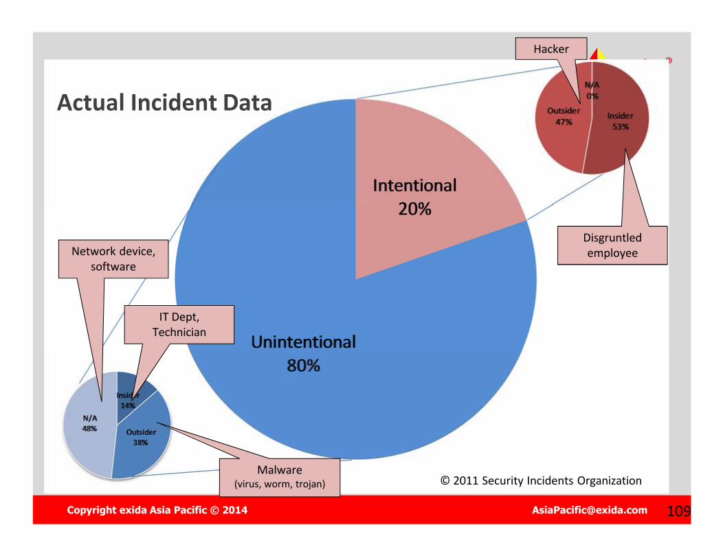
Actual Incident Data
Malware(virus, worm, trojan)
IT Dept, Technician
Network device, software
Disgruntled employee
Hacker
© 2011 Security Incidents Organization
Copyright exida Asia Pacific © 2014 [email protected] 110110
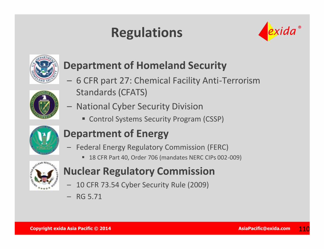
Regulations
Department of Homeland Security– 6 CFR part 27: Chemical Facility Anti-Terrorism
Standards (CFATS)– National Cyber Security Division
Control Systems Security Program (CSSP)
Department of Energy– Federal Energy Regulatory Commission (FERC)
18 CFR Part 40, Order 706 (mandates NERC CIPs 002-009)
Nuclear Regulatory Commission– 10 CFR 73.54 Cyber Security Rule (2009)– RG 5.71
Copyright exida Asia Pacific © 2014 [email protected] 111111
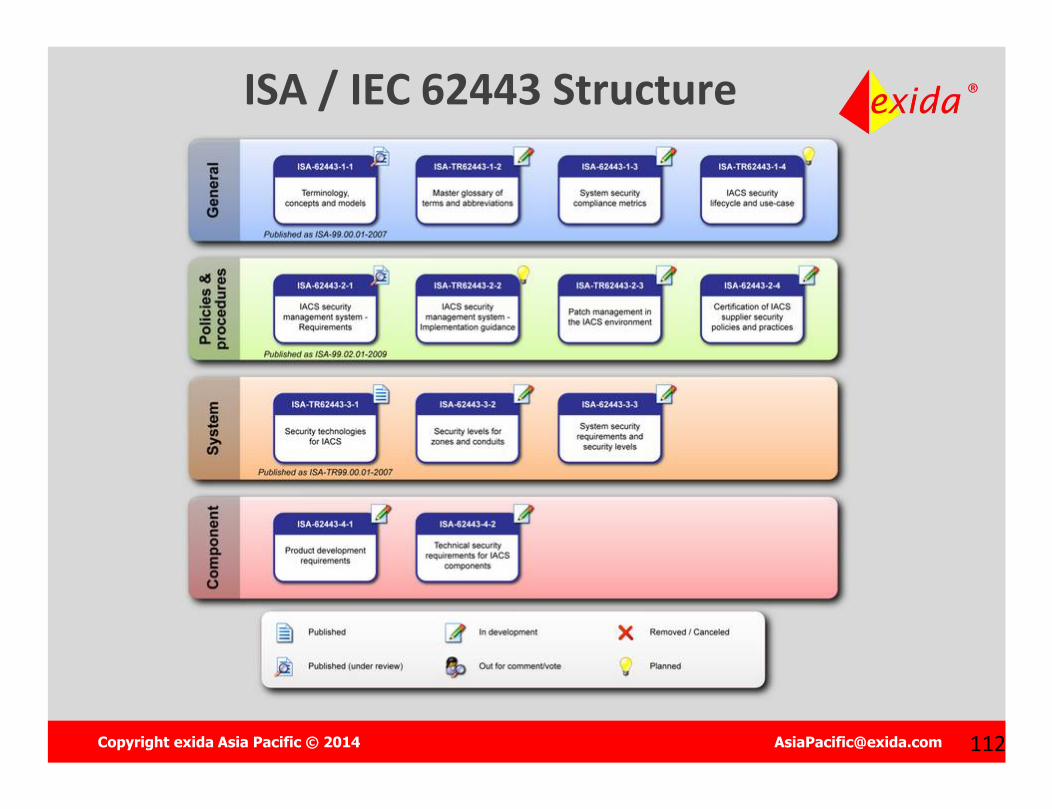
Standards
International Society for Automation (ISA)– ISA 62443 Industrial Automation and Control System (IACS)
Security (was ISA 99)
International Electrotechnical Commission (IEC)– IEC 62443 series of standards (equivalent to ISA 99)
National Institute for Standards and Technology (NIST)– SP800-82 Guide to Industrial Control Systems (ICS) Security


Copyright exida Asia Pacific © 2014 [email protected] 114114
Key Principles for Securing ICSStep 1 – Assess Existing SystemsStep 2 – Document Policies & ProceduresStep 3 – Train Personnel & ContractorsStep 4 – Segment the Control System NetworkStep 5 – Control Access to the SystemStep 6 – Harden the Components of the SystemStep 7 – Monitor & Maintain System Security

Copyright exida Asia Pacific © 2014 [email protected] 115115
exida Functional Integrity Certification™
Functional Integrity Certification™
Functional Safety Certification ™
+Functional Security Certification ™
“Integrity is doing the right thing, even if nobody is watching.”
(Anonymous)
“Integrity is doing the right thing, even if nobody is watching.”
(Anonymous)
Copyright exida Asia Pacific © 2014 [email protected] 130130
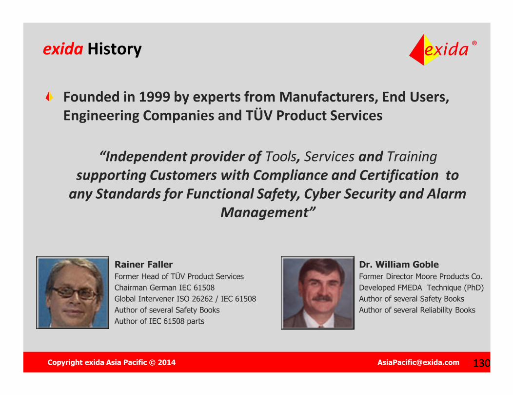
exida History
Founded in 1999 by experts from Manufacturers, End Users, Engineering Companies and TÜV Product Services
“Independent provider of Tools, Services and Trainingsupporting Customers with Compliance and Certification to
any Standards for Functional Safety, Cyber Security and Alarm Management”
Rainer FallerFormer Head of TÜV Product ServicesChairman German IEC 61508Global Intervener ISO 26262 / IEC 61508Author of several Safety BooksAuthor of IEC 61508 parts
Dr. William GobleFormer Director Moore Products Co.Developed FMEDA Technique (PhD) Author of several Safety BooksAuthor of several Reliability Books
Copyright exida Asia Pacific © 2014 [email protected] 131131
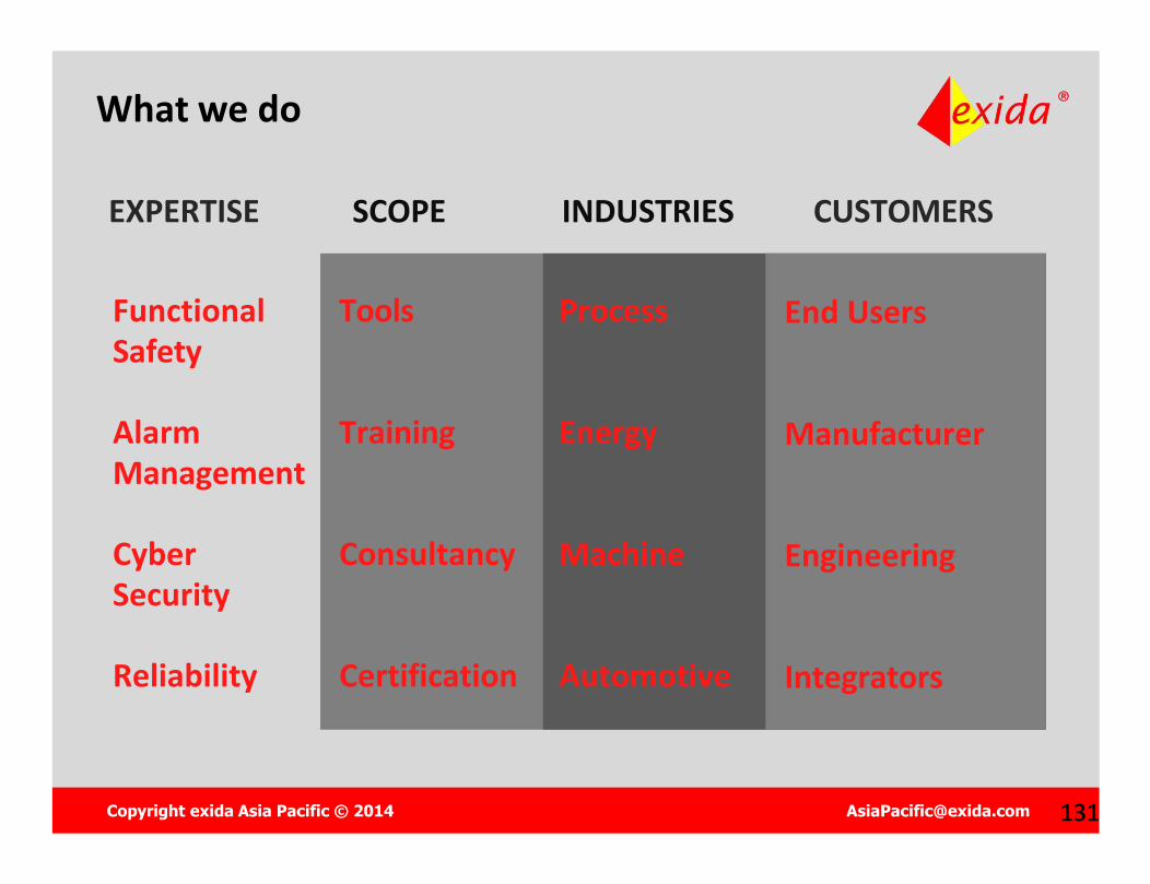
What we do
EXPERTISE SCOPE
Tools
Training
Consultancy
Certification
INDUSTRIES
Process
Energy
Machine
Automotive
End Users
Manufacturer
Engineering
Integrators
CUSTOMERS
Functional Safety
Alarm Management
Cyber Security
Reliability
Copyright exida Asia Pacific © 2014 [email protected] 133133
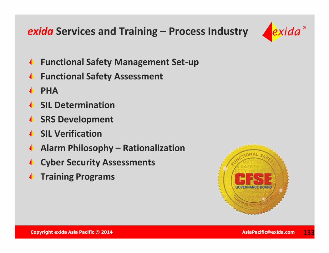
exida Services and Training – Process Industry
Functional Safety Management Set-upFunctional Safety AssessmentPHASIL Determination SRS DevelopmentSIL VerificationAlarm Philosophy – RationalizationCyber Security AssessmentsTraining Programs
Copyright exida Asia Pacific © 2014 [email protected] 135135
Global Functional Safety Certification Consultant3rd Party Accredited Certification Body Developer FMEDA TechniqueMechanical Failure DatabaseElectrical & Electronic Failure DatabaseInstrument & Equipment Failure DatabaseDevelopment Field Failure Database MethodologyGlobal Active Participation in IEC – ISO WorkgroupsFunctional Safety Engineering Tools
exida Industry Contributions
Copyright exida Asia Pacific © 2014 [email protected] 136
Experience – exida has done more certification projects in the process industries for currently marketed products than any other certification company. Excellence / Competency - We have staff with a cumulative experience of several hundred years in automation functional safety and dependability. exida is active in the 61508 (functional safety) and ISA 99 (security)committee and has developed many of the functional safety analysis techniques. Market Support / Data – exida supports the end user with analysis and data. That data goes into the exSILentia tool. exida provides training for field personnel. Broad Capabilities – exida can offer functional safety, security and Integrity Certification
Why exida Certification?
Copyright exida Asia Pacific © 2014 [email protected] 137137
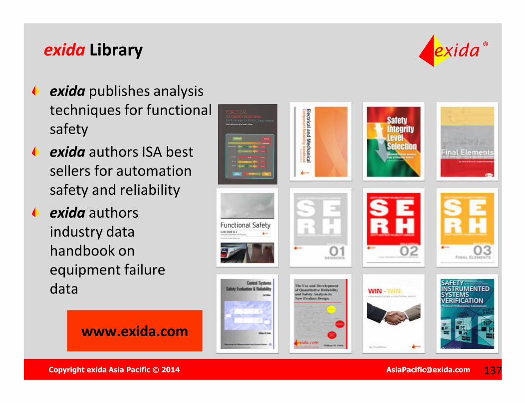
exida Library
exida publishes analysistechniques for functional safetyexida authors ISA best sellers for automationsafety and reliabilityexida authorsindustry data handbook onequipment failuredata
www.exida.comwww.exida.com