applying shielded metal arc welding (smaw)...
TRANSCRIPT
Applying Shielded Metal ArcWelding (SMAW) Techniques
ANCIENT WELDERS and tools havebeen seen depicted on Egyptian
tombs. Welding may be viewed as anancient art, but the science ofshielded metal arc welding and otherwelding processes is relatively new.Developments in the welding processand discoveries in metallurgy have ledto technological wonders and havechanged how we fabricate and build.
Objective:
� Explain the fundamentals and techniques of shielded metal arc welding.
Key Terms:
�
Arc Welding
Arc welding uses heat from an electrical source for the melting or fusion of metals. Weld-
ing is the melting, flowing together, and freezing of metals under controlled conditions. Arc
welding is a process that uses electricity to heat and melt the metal. A weldor is the person
E-unit: Applying Shielded Metal Arc Welding (SMAW) Techniques
Page 1 � www.MyCAERT.com
Copyright © by CAERT, Inc. — Reproduction by subscription only. 090046
alternating current
amperage
arc length
arc welding
conductor
crater
direct current
duty cycle
electricity
electrode
electrons
fillet weld
groove weld
padding
polarity
resistance
shielded metal arcwelding
surface welds
voltage
weaving
weld root
welder
welding
weldor
doing the welding, but a welder is the machine doing the welding. Shielded metal arc
welding is welding in which fusion is produced by heating with an arc between a consumable
stick electrode and the work piece. An electrode is a bare metal rod that is usually coated
with chemical compounds called flux. The flux coatings burn in the intense heat and form a
blanket of smoke and gas that shields the weld puddle from the air.
TERMS
The arc welding process and principles are based around the source of electricity. There-
fore, it is necessary to have a fundamental knowledge of electricity and how it is used for weld-
ing. Electricity is the flow of tiny particles called electrons through a conductor. Electrons
are negatively charged particles, and a conductor is something that allows the flow of elec-
trons. Voltage, meanwhile, is a measure of electrical pressure. Most welders operate on a 220-
volt source. A welder changes or transforms the 220-volt pressure to a much lower pressure at
the electrode, usually between 15 and 25 volts. Amperage is a measure of electrical current
flowing through a circuit and is an indication of the heat being produced. The amount of cur-
rent available is determined by the amperage setting on the welder.
Polarity is the direction in which the current is flowing, while resistance is the opposi-
tion to the flow of current in a circuit. Resistance is what causes the electric energy to be trans-
formed into heat. When electricity is conducted through a conductor, the movement of the
electric energy heats the conductor due to the resistance of the conductor to the flow of elec-
tric current through it. The greater the flow of current through a conductor, the greater the
resistance to it, and the greater the heat generated. Therefore, the higher the amperage setting,
the greater the heat produced. When electrical current alternates or reverses the direction of
electron flow, it is called alternating current (AC). The arc is extinguished every half-cycle
as the current passes through zero, usually at the rate of 120 times per second. Electron flow in
one direction is called direct current (DC), which is either straight polarity (DCSP) or
reverse polarity (DCRP).
HISTORY
The art of welding is ancient, but the science of shielded metal arc welding is relatively new.
In 1801, an English scientist discovered that an electric current would form an arc when forced
across a gap. A French inventor used the carbon arc in 1881. Then in 1887, a Russian improved
on the carbon arc and patented the process. In the same year, another Russian discovered that a
bare metal rod would melt off by the heat of the arc and act as a filler metal in a weld. In 1889,
an American experimented with the metallic arc and received a patent. A bare electrode was
difficult to use and resulted in a weld that was porous, brittle, and not as strong as the base
metal. A Swede found that welds were stronger and easier to make when a chemical coating
was put on the metal electrode in 1910. The coating was called flux because it cleaned the
metal and aided in mixing the filler metal with the base metal. However, it was difficult to
apply. In 1927, mass production methods developed to apply the flux to the bare metal rod.
E-unit: Applying Shielded Metal Arc Welding (SMAW) Techniques
Page 2 � www.MyCAERT.com
Copyright © by CAERT, Inc. — Reproduction by subscription only. 090046
CLASSIFICATION
Welding machines are classified in several ways. One common way is by the type of output
current produced by the welder: AC, DC, or AC/DC. Another way to classify welders is by
their service. Limited input welders provide satisfactory operation and are fairly inexpensive to
operate. The cost is about $1 per ampere of output. Limited service welders are used where
lower cost is desired because the operation is quite intermittent. Industrial welders have a high
duty cycle, but their price is much higher.
Welders are also classified by power source. An electric motor-driven welder is self-con-
tained and requires three-phase power. Electric power runs the motor, which turns a generator
to produce DC welding current. An internal combustion engine drives a generator that pro-
duces the power for the welder to
run. In contrast, line voltage welders
run on the power supplied by the
power company.
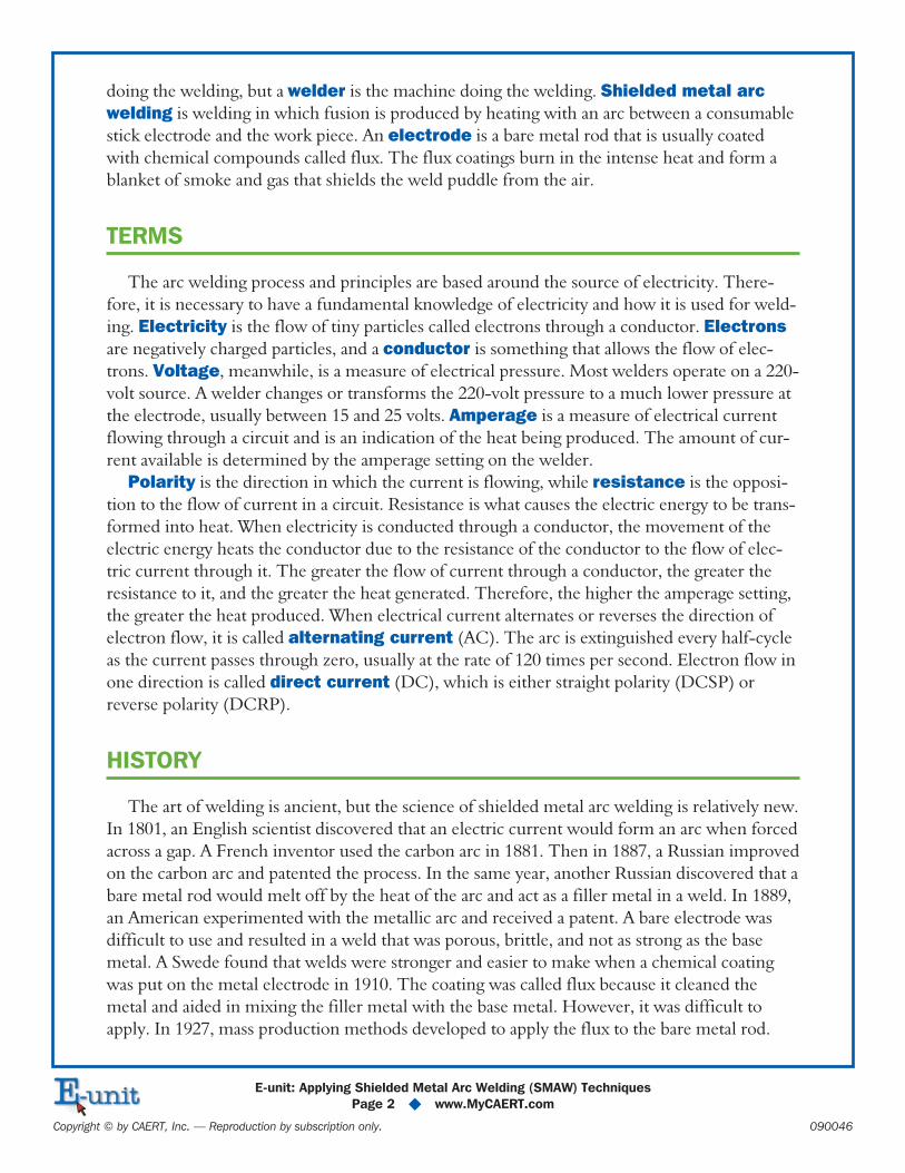
A fourth classification of welding
machines is how long the machine
can operate. A duty cycle is the per-
centage of a 10-minute period in
which a welder can operate at a given
current setting and is another way to
classify welders. A welder with a 60
percent duty cycle can be operated
safely for six minutes of a ten-minute
cycle, repeated indefinitely. The duty
cycle will be shorter if the welder is
used at higher settings. Likewise, if
the welder operates at lower settings,
the cycle will be longer.
When buying a new welder, con-
sider only one made by a well-known
manufacturer and distributed by a
reliable dealer. Check the nameplate
to see if the welder is National Elec-
trical Manufacturers Association
(NEMA) rated and is approved and
listed by Underwriters Laboratories
(UL). Compare prices of welders,
equal capacity, and the kinds of acces-
sories available. Read the guarantee
carefully, and ask questions.
E-unit: Applying Shielded Metal Arc Welding (SMAW) Techniques
Page 3 � www.MyCAERT.com
Copyright © by CAERT, Inc. — Reproduction by subscription only. 090046
FIGURE 1. Welding machines.
EQUIPMENT AND SUPPLIES
Several other pieces of equipment and supplies are necessary to operate the shield metal arc
welder.
� Two cables: No. 2 gauge
� An electrode holder that grips the electrode during welding and should be completelyinsulated, have a spring-grip release, and jaws that hold rods in 60-, 90-, 120-, and 180-degree positions in relation to the handle
� A ground clamp fastened to the work or to the welding table
� A chipping hammer, with a straight peen and a straight cone with a spiral wire-grip that isnecessary to remove slag from the weld bead
� A wire brush used to clean dirt, rust, and slag from metal
� Pliers needed for handlinghot metal
� Safety glasses or goggles
� Full gauntlet leather gloves
� Upper body protection
� A head shield to offer pro-tection from the rays of theelectric arc, heat, and spatterof the molten metal
� Filter lenses (No. 10 lensmeets applications up to 200amps)
� Electrodes
Electrodes
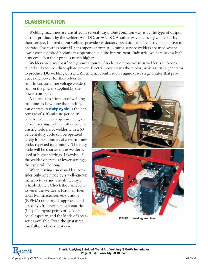
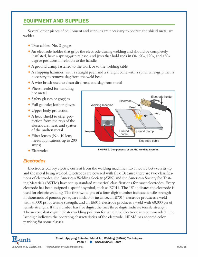
Electrodes convey electric current from the welding machine into a hot arc between its tip
and the metal being welded. Electrodes are covered with flux. Because there are two classifica-
tions of electrodes, the American Welding Society (AWS) and the American Society for Test-
ing Materials (ASTM) have set up standard numerical classifications for most electrodes. Every
electrode has been assigned a specific symbol, such as E7014. The “E” indicates the electrode is
used for electric welding. The first two digits of a four-digit number indicate tensile strength
in thousands of pounds per square inch. For instance, an E7014 electrode produces a weld
with 70,000 psi of tensile strength, and an E6011 electrode produces a weld with 60,000 psi of
tensile strength. If the number has five digits, the first three digits indicate tensile strength.
The next-to-last digit indicates welding position for which the electrode is recommended. The
last digit indicates the operating characteristics of the electrode. NEMA has adopted color
marking for some classes.
E-unit: Applying Shielded Metal Arc Welding (SMAW) Techniques
Page 4 � www.MyCAERT.com
Copyright © by CAERT, Inc. — Reproduction by subscription only. 090046
Welding machineBead
Electrode
Electrode holder
Arc
Ground clamp
Electrode cable
Groundcable
FIGURE 2. Components of an ARC welding system.
PREPARATION
One of the most important and most often neglected parts of the welding job is preparation
of the metal for welding. The metal must be free of dirt, grease, rust, paint, and other impuri-
ties that may combine with a molten weld bead and cause it to be weakened. Metal should be
cleaned by grinding, brushing, filing, or cutting before welding occurs.
COMMON WELDS
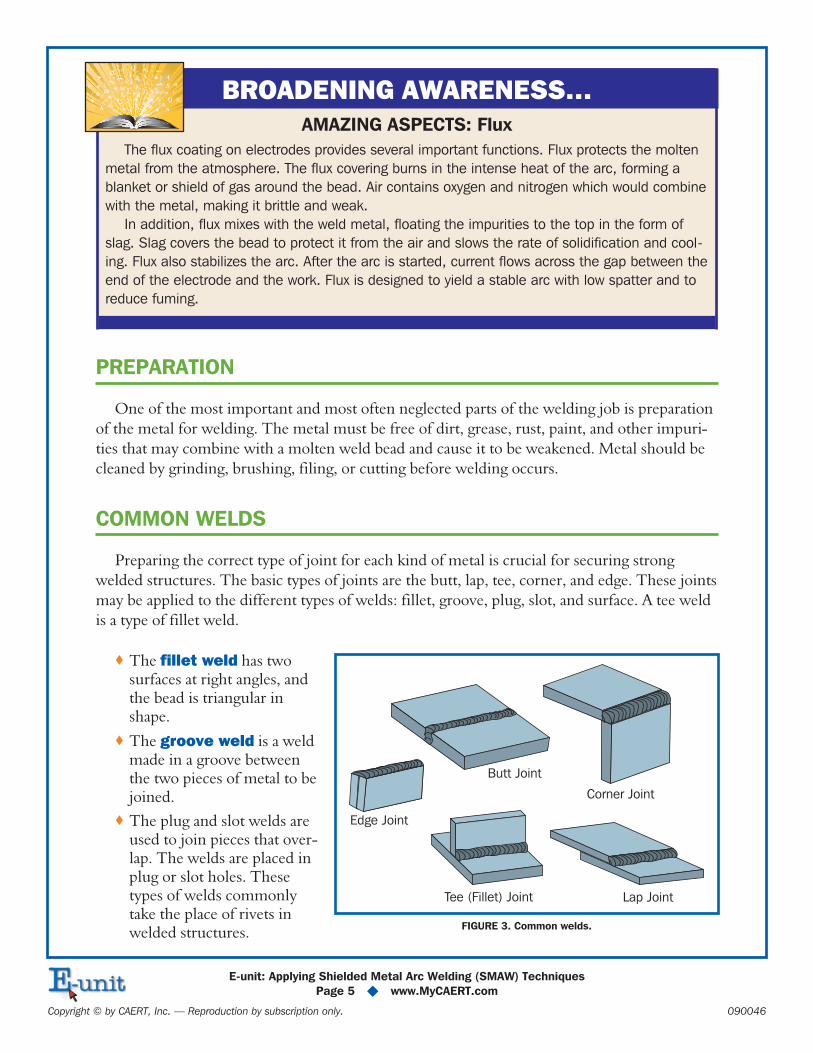
Preparing the correct type of joint for each kind of metal is crucial for securing strong
welded structures. The basic types of joints are the butt, lap, tee, corner, and edge. These joints
may be applied to the different types of welds: fillet, groove, plug, slot, and surface. A tee weld
is a type of fillet weld.
� The fillet weld has twosurfaces at right angles, andthe bead is triangular inshape.
� The groove weld is a weldmade in a groove betweenthe two pieces of metal to bejoined.
� The plug and slot welds areused to join pieces that over-lap. The welds are placed inplug or slot holes. Thesetypes of welds commonlytake the place of rivets inwelded structures.
E-unit: Applying Shielded Metal Arc Welding (SMAW) Techniques
Page 5 � www.MyCAERT.com
Copyright © by CAERT, Inc. — Reproduction by subscription only. 090046
BROADENING AWARENESS…
AMAZING ASPECTS: Flux
The flux coating on electrodes provides several important functions. Flux protects the molten
metal from the atmosphere. The flux covering burns in the intense heat of the arc, forming a
blanket or shield of gas around the bead. Air contains oxygen and nitrogen which would combine
with the metal, making it brittle and weak.
In addition, flux mixes with the weld metal, floating the impurities to the top in the form of
slag. Slag covers the bead to protect it from the air and slows the rate of solidification and cool-
ing. Flux also stabilizes the arc. After the arc is started, current flows across the gap between the
end of the electrode and the work. Flux is designed to yield a stable arc with low spatter and to
reduce fuming.
Butt Joint
Corner Joint
Edge Joint
Lap JointTee (Fillet) Joint
FIGURE 3. Common welds.
� Surface welds are beads deposited on a metal surface for the purpose of building upthe base metal.
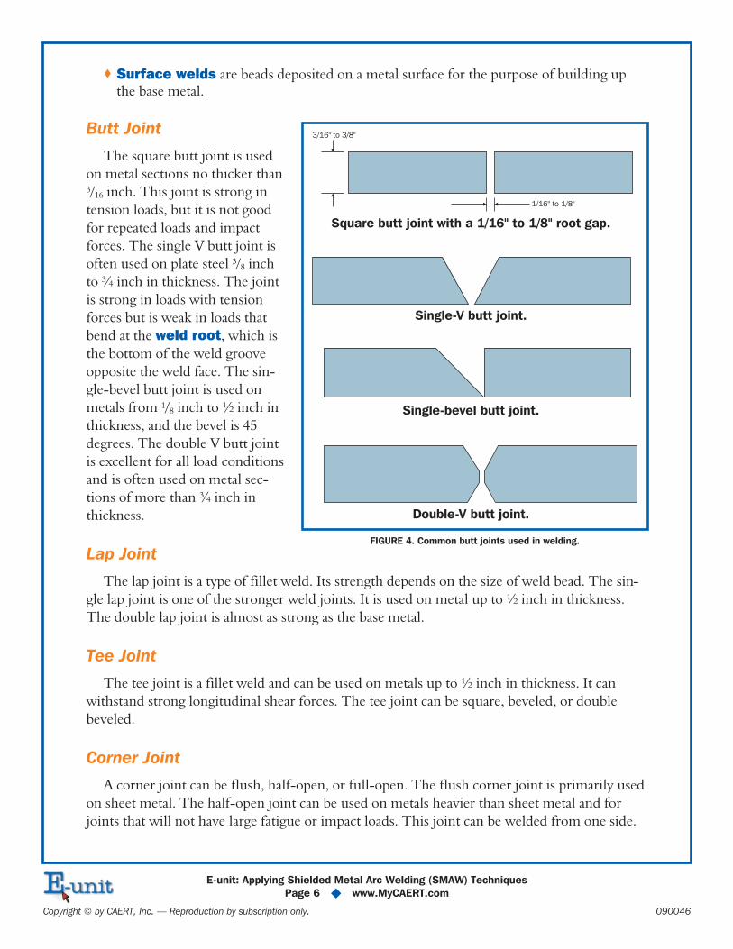
Butt Joint
The square butt joint is used
on metal sections no thicker than3/16 inch. This joint is strong in
tension loads, but it is not good
for repeated loads and impact
forces. The single V butt joint is
often used on plate steel 3/8 inch
to ¾ inch in thickness. The joint
is strong in loads with tension
forces but is weak in loads that
bend at the weld root, which is
the bottom of the weld groove
opposite the weld face. The sin-
gle-bevel butt joint is used on
metals from 1/8 inch to ½ inch in
thickness, and the bevel is 45
degrees. The double V butt joint
is excellent for all load conditions
and is often used on metal sec-
tions of more than ¾ inch in
thickness.
Lap Joint
The lap joint is a type of fillet weld. Its strength depends on the size of weld bead. The sin-
gle lap joint is one of the stronger weld joints. It is used on metal up to ½ inch in thickness.
The double lap joint is almost as strong as the base metal.
Tee Joint
The tee joint is a fillet weld and can be used on metals up to ½ inch in thickness. It can
withstand strong longitudinal shear forces. The tee joint can be square, beveled, or double
beveled.
Corner Joint
A corner joint can be flush, half-open, or full-open. The flush corner joint is primarily used
on sheet metal. The half-open joint can be used on metals heavier than sheet metal and for
joints that will not have large fatigue or impact loads. This joint can be welded from one side.
E-unit: Applying Shielded Metal Arc Welding (SMAW) Techniques
Page 6 � www.MyCAERT.com
Copyright © by CAERT, Inc. — Reproduction by subscription only. 090046
3/16" to 3/8"
1/16" to 1/8"
Square butt joint with a 1/16" to 1/8" root gap.
Single-V butt joint.
Single-bevel butt joint.
Double-V butt joint.
FIGURE 4. Common butt joints used in welding.
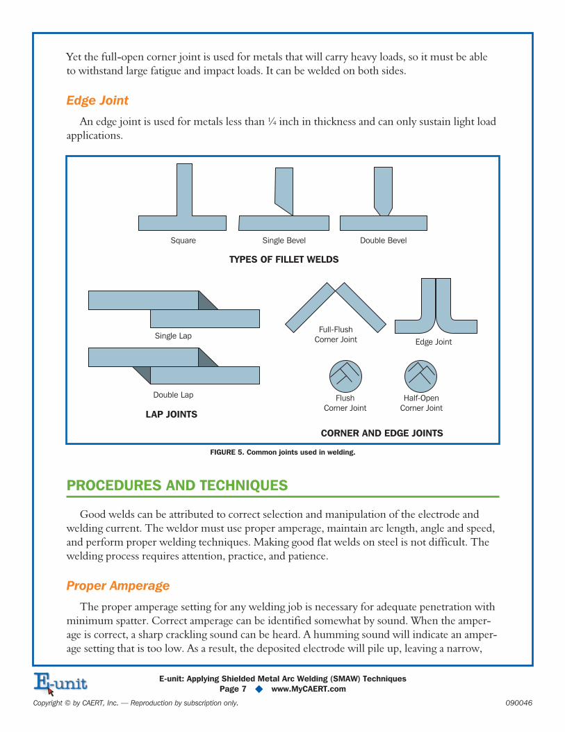
Yet the full-open corner joint is used for metals that will carry heavy loads, so it must be able
to withstand large fatigue and impact loads. It can be welded on both sides.
Edge Joint
An edge joint is used for metals less than ¼ inch in thickness and can only sustain light load
applications.
PROCEDURES AND TECHNIQUES
Good welds can be attributed to correct selection and manipulation of the electrode and
welding current. The weldor must use proper amperage, maintain arc length, angle and speed,
and perform proper welding techniques. Making good flat welds on steel is not difficult. The
welding process requires attention, practice, and patience.
Proper Amperage
The proper amperage setting for any welding job is necessary for adequate penetration with
minimum spatter. Correct amperage can be identified somewhat by sound. When the amper-
age is correct, a sharp crackling sound can be heard. A humming sound will indicate an amper-
age setting that is too low. As a result, the deposited electrode will pile up, leaving a narrow,
E-unit: Applying Shielded Metal Arc Welding (SMAW) Techniques
Page 7 � www.MyCAERT.com
Copyright © by CAERT, Inc. — Reproduction by subscription only. 090046
Square
Single Lap
Double Lap
Single Bevel
TYPES OF FILLET WELDS
LAP JOINTS
CORNER AND EDGE JOINTS
Edge Joint
Full-Flush
Corner Joint
Flush
Corner Joint
Half-Open
Corner Joint
Double Bevel
FIGURE 5. Common joints used in welding.
high bead that has poor penetration and little strength. A popping sound will indicate too high
of an amperage setting, and the bead will be flat with excessive spatter. The electrode will
become red hot, and the metal along the edge of the bead will be undercut. The correct amp
setting depends on the thickness of the base metal and the diameter of the electrode.
Arc Length, Angle, and Speed
Learning to maintain the correct arc length for the electrode you are using is necessary to be
successful. Arc length is the distance from the tip of the bare end of the electrode to the base
metal. Arc length is equal to the diameter of the bare end of the electrode.
The correct angle of the electrode will depend on the type of weld to be completed. Hold
the electrode at a 90-degree angle to the work as viewed from the end of the two plates being
joined and 5 to 15 degrees in the direction of travel. The correct speed of travel affects the
amount of electrode deposited and the uniformity of the bead. It should produce a bead that is
1.5 to 2 times the diameter of the bare end of the electrode.
Striking the Arc and Welding
Following proper procedures when preparing to weld and striking the arc will develop con-
fidence in your abilities.
1. Prepare the work area so everything is ready and convenient before you start.
2. Make a final check to see that flammable materials are out of the way and unnecessary
tools are not lying around.
3. Be sure the machine is turned off.
4. Set the machine to the desired amperage.
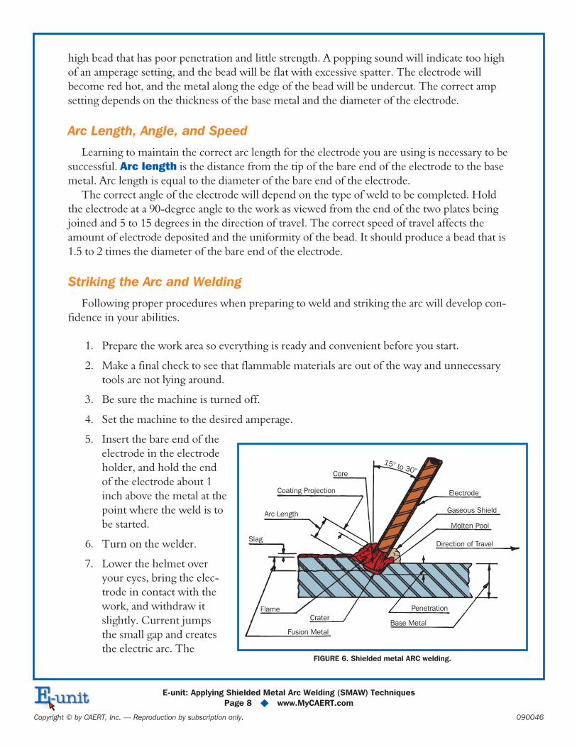
5. Insert the bare end of the
electrode in the electrode
holder, and hold the end
of the electrode about 1
inch above the metal at the
point where the weld is to
be started.
6. Turn on the welder.
7. Lower the helmet over
your eyes, bring the elec-
trode in contact with the
work, and withdraw it
slightly. Current jumps
the small gap and creates
the electric arc. The
E-unit: Applying Shielded Metal Arc Welding (SMAW) Techniques
Page 8 � www.MyCAERT.com
Copyright © by CAERT, Inc. — Reproduction by subscription only. 090046
Core
Coating Projection
Arc Length
Slag
Electrode
Gaseous Shield
Molten Pool
Direction of Travel
Base Metal
Penetration
Crater
Fusion Metal
Flame
15° to 30°
FIGURE 6. Shielded metal ARC welding.
moment the arc is struck, the concentration of intense heat, estimated between 6000°
and 9000°F, melts the base metal and the end of the electrode and forms a molten metal
pool called a crater.
8. There are two methods used in starting the arc. A striking movement is similar to strik-
ing a match. A tapping movement involves the electrode being quickly tapped on the
surface of the metal to prevent it from sticking to the base metal. If the electrode is not
instantly pulled away, it will fuse with the base metal and stick. If the electrode is pulled
too far away, the arc will be extinguished.
9. Raise the tip of the electrode to about 3/16 inch above the base metal to form a long arc
that is held for a three count to preheat the base metal.
10. Lower the electrode to the correct arc length.
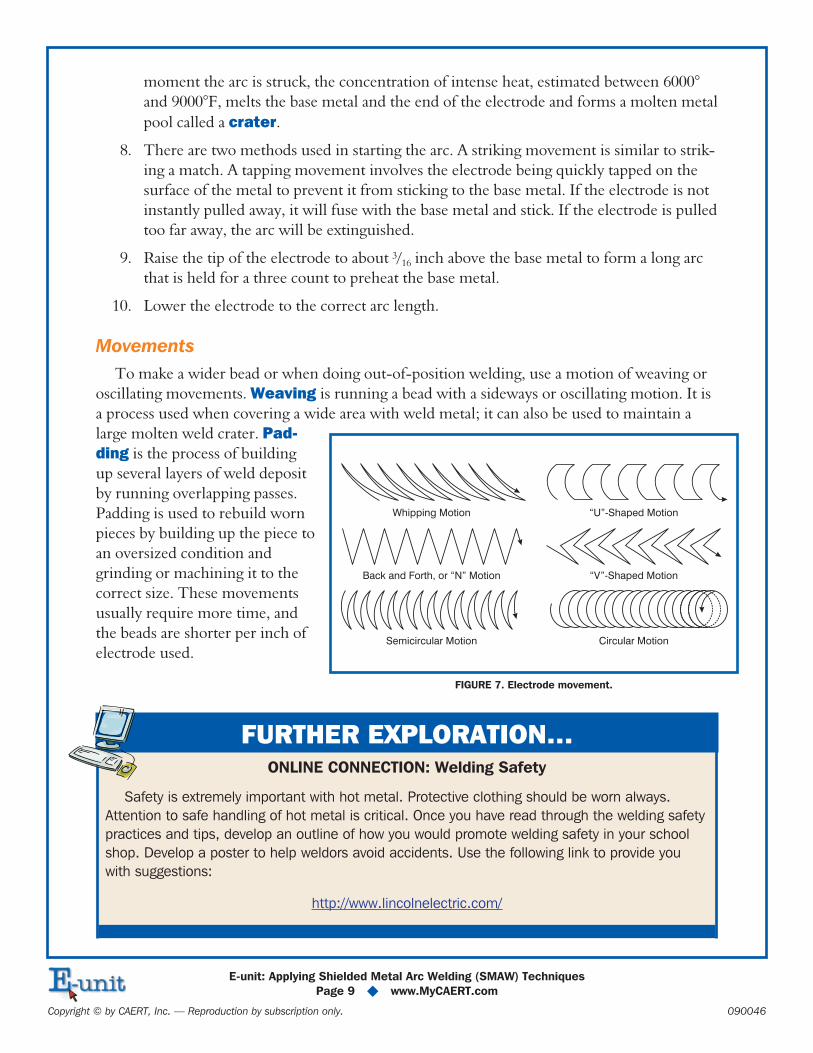
Movements
To make a wider bead or when doing out-of-position welding, use a motion of weaving or
oscillating movements. Weaving is running a bead with a sideways or oscillating motion. It is
a process used when covering a wide area with weld metal; it can also be used to maintain a
large molten weld crater. Pad-
ding is the process of building
up several layers of weld deposit
by running overlapping passes.
Padding is used to rebuild worn
pieces by building up the piece to
an oversized condition and
grinding or machining it to the
correct size. These movements
usually require more time, and
the beads are shorter per inch of
electrode used.
E-unit: Applying Shielded Metal Arc Welding (SMAW) Techniques
Page 9 � www.MyCAERT.com
Copyright © by CAERT, Inc. — Reproduction by subscription only. 090046
Whipping Motion
Back and Forth, or “N” Motion
Semicircular Motion
“U”-Shaped Motion
“V”-Shaped Motion
Circular Motion
FIGURE 7. Electrode movement.
FURTHER EXPLORATION…ONLINE CONNECTION: Welding Safety
Safety is extremely important with hot metal. Protective clothing should be worn always.
Attention to safe handling of hot metal is critical. Once you have read through the welding safety
practices and tips, develop an outline of how you would promote welding safety in your school
shop. Develop a poster to help weldors avoid accidents. Use the following link to provide you
with suggestions:
http://www.lincolnelectric.com/
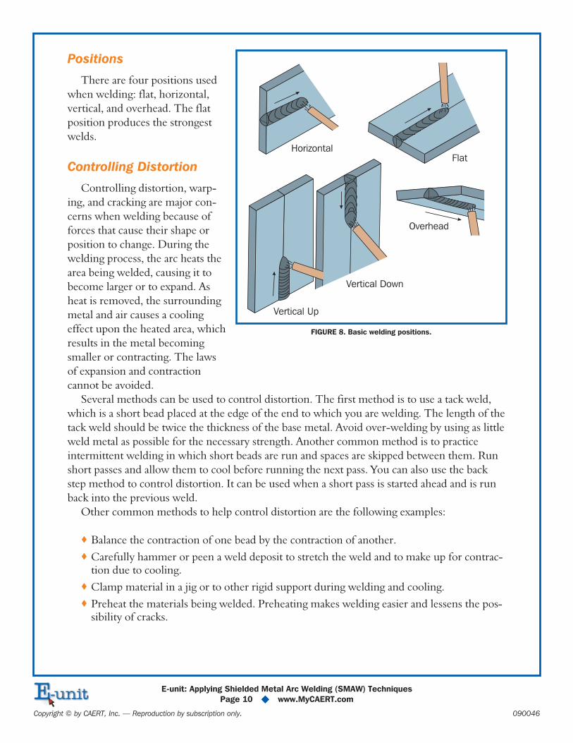
Positions
There are four positions used
when welding: flat, horizontal,
vertical, and overhead. The flat
position produces the strongest
welds.
Controlling Distortion
Controlling distortion, warp-
ing, and cracking are major con-
cerns when welding because of
forces that cause their shape or
position to change. During the
welding process, the arc heats the
area being welded, causing it to
become larger or to expand. As
heat is removed, the surrounding
metal and air causes a cooling
effect upon the heated area, which
results in the metal becoming
smaller or contracting. The laws
of expansion and contraction
cannot be avoided.
Several methods can be used to control distortion. The first method is to use a tack weld,
which is a short bead placed at the edge of the end to which you are welding. The length of the
tack weld should be twice the thickness of the base metal. Avoid over-welding by using as little
weld metal as possible for the necessary strength. Another common method is to practice
intermittent welding in which short beads are run and spaces are skipped between them. Run
short passes and allow them to cool before running the next pass. You can also use the back
step method to control distortion. It can be used when a short pass is started ahead and is run
back into the previous weld.
Other common methods to help control distortion are the following examples:
� Balance the contraction of one bead by the contraction of another.
� Carefully hammer or peen a weld deposit to stretch the weld and to make up for contrac-tion due to cooling.
� Clamp material in a jig or to other rigid support during welding and cooling.
� Preheat the materials being welded. Preheating makes welding easier and lessens the pos-sibility of cracks.
E-unit: Applying Shielded Metal Arc Welding (SMAW) Techniques
Page 10 � www.MyCAERT.com
Copyright © by CAERT, Inc. — Reproduction by subscription only. 090046
Horizontal
Vertical Up
Vertical Down
Overhead
Flat
FIGURE 8. Basic welding positions.
SAFETY PRACTICES
Arc welding creates many dangers to the eyes and body. The brightest of the light can cause
severe burns and injury to the eyes and skin. Read the following suggested practices and tips to
minimize and/or eliminate shop accidents when arc welding.
Protective Wear
Always wear a welding helmet with an approved lens that is in good condition. A welding
helmet protects from the rays of the electric arc as well as the heat and spatter of the molten
metal. Use only filter lenses that are clearly labeled with standard shade numbers. Be sure they
meet the specifications of the welding you are performing.
Upper body protection is necessary to protect against rays, heat, spatter, and slag while
welding. Wear leather or special fabric gloves at all times to protect from hot electrodes, parti-
cles of spatter and slag, and the metal being welded. Wear high-top shoes to protect your feet
and ankles from burns caused by weld spatter. Do not wear clothing with turned up cuffs, and
keep your collar and pockets buttoned. Oily, greasy, and/or ragged clothing should not be
worn. If leather clothing is not available, wear wool clothing rather than cotton. Wool does not
ignite as readily, and it provides better protection from heat.
Equipment and Material Safety
Welding cables should be inspected for broken insulation and frayed conductors. Also, elec-
trode holders and ground clamps should be checked for positive connections before beginning
to weld. Loose connections and grounds may prove to be dangerous. In addition, the work area
should be dry. If floors are damp, protective shoes should be worn (e.g., rubber-soled shoes).
All combustible materials should be cleared away from the welding area before beginning to
weld. It is important to keep matches, lighters, papers, and cellophane wrappers out of pockets
as these items ignite quickly and/or may explode. It is possible for flying sparks from the spat-
ter to reach several feet from the welding operation. Sparks could ignite combustible materials,
so the welding area should be cleared of rags, straw, paper, shavings, and other combustible
items before starting to weld.
An exhaust system should be turned on before you begin. Welding fumes can spread to all
parts of the shop and may result in injuries if inhaled. Special measures need to be taken to
avoid noxious fumes that occur when welding or cutting metals containing zinc. Inhaling zinc
fumes will cause you to feel ill for several hours after welding.
Work Environment Safety
Protect other workers by using a welding screen to enclose your area. Warn people standing
nearby, by saying “cover,” to cover their eyes when you are ready to strike an arc. You should
never look directly at the arc without protecting your eyes. The rays can penetrate through
closed eyelids if you are welding at close range. Do not wear contact lenses while welding or
E-unit: Applying Shielded Metal Arc Welding (SMAW) Techniques
Page 11 � www.MyCAERT.com
Copyright © by CAERT, Inc. — Reproduction by subscription only. 090046

around a welder. Do not chip slag from a weld unless your eyes and those of others near you
are protected by safety glasses.
A weldor should be on alert for fires. The operator’s helmet is lowered, so clothing may
catch fire without being noticed. In case of a clothing fire, strip off the article, if possible. Wrap
yourself in a fire blanket, or improvise with a coat or a piece of canvas. If there is nothing at
hand to wrap in, drop to the floor and roll slowly. In case of eye or skin burns, get first-aid
treatment. All burns and injuries should be reported immediately to the instructor.
Hot metal should be handled with tongs or pliers to prevent burning your hands or gloves.
Hot metal needs to be placed where no one will come in contact with it. An important habit to
develop is feeling all of the metal cautiously before picking it up. Hot metal should not be left
where it may be picked up or stepped on.
The welder should be disconnected when repairing or adjusting it. At the end of the work
day, welders and equipment should be unplugged, and all equipment should be put away. Pro-
tect fuel tanks and fuel lines with wet sheet asbestos when welding near motors or power
units. Clean accumulations of dry trash, husks, lint, and chaff off of farm machinery before
welding. The paint on machinery may start to burn from the heat of welding.
Summary:
� Shielded metal arc welding is welding in which fusion is produced by heating withan arc between a consumable stick electrode and the work piece. Arc welding useselectricity to generate heat. Common knowledge of basic electrical functions is nec-essary.
Welding machines are classified in several ways. One common way is by the type ofoutput current produced: AC, DC, or AC/DC. They can also be classified by theirservice or by their power source. Another classification is how long the machine canoperate.
Arc welding requires several other pieces of equipment and supplies. Preparation isone of the most important parts. Part of preparation is expressing the knowledge ofcommon welds and joints. Once preparation is successfully completed, proper pro-cedures and techniques need to be used and followed. Arc welding poses great dan-gers to eyes and skin, so it is important to wear a proper helmet, protective clothing.Also, welders should follow safety measures and should be attentive to others.
Checking Your Knowledge:
� 1. What is an advantage of using shielded metal arc welding?
2. How are welding machines classified?
3. What equipment is needed in order to operate the shield metal arc welder?
E-unit: Applying Shielded Metal Arc Welding (SMAW) Techniques
Page 12 � www.MyCAERT.com
Copyright © by CAERT, Inc. — Reproduction by subscription only. 090046
4. What do the digits on an electrode indicate?
5. How can distortion, warping, and cracking be controlled?
Expanding Your Knowledge:
� How do you store electrodes? Can electrodes just sit out on the work station untilneeded? Can moisture or humidity cause damage to electrodes? Research theproper storage practices for electrodes. Use the following article for assistance:http://www.keenovens.com/articles/store-rods.htm
Web Links:
� Arc Welding Safety
http://nasdonline.org/document/1087/d000873/arc-welding-safety.html
Welding Electrodes
http://www.metalwebnews.com/howto/weldrod.html
Guidelines for Shielded Metal Arc Welding
http://www.millerwelds.com/pdf/guidelines_smaw.pdf
E-unit: Applying Shielded Metal Arc Welding (SMAW) Techniques
Page 13 � www.MyCAERT.com
Copyright © by CAERT, Inc. — Reproduction by subscription only. 090046