applying metal inert gas (mig) welding techniques€¦ · lesson a5–7 applying metal inert gas...
TRANSCRIPT
Lesson A5–7
Applying Metal Inert Gas (MIG)
Welding Techniques
Unit A. Mechanical Systems and Technology
Problem Area 5. Metal Fabrication
Lesson 7. Applying Metal Inert Gas (MIG) Welding Techniques
New Mexico Content Standard:
Pathway Strand: Power, Structural and Technical Systems
Standard: VIII: Plan, implement, manage, and/or provide support services to facility
design and construction; equipment design, manufacture, repair, and service; and agri-
cultural technology.
Benchmark: VIII-B: Follow architectural and mechanical plans to construct building and
facilities.
Performance Standard: 1. Identify and select appropriate building materials. 3. Con-
struct with wood and metal.
Student Learning Objectives. Instruction in this lesson should result in students
achieving the following objectives:
1. Explain the advantages of the metal inert gas (MIG) welding process.
2. Describe the equipment, types of shielding gases, and electrodes used in the MIG weld-ing process.
3. Describe the types of metal transfer patterns used in MIG welding and relate their appli-cations.
4. Describe the correct techniques for starting, controlling, and stopping an MIG bead.
5. Explain how to adjust and maintain the MIG welder.
6. Identify safety practices that should be observed in MIG welding.
New Mexico Agricultural Mechanics and Technology Lesson Plan Library
Unit A. Problem Area 5. Lesson 7. Page 1.
List of Resources. The following resources may be useful in teaching this lesson:
Recommended Resources. One of the following resources should be selected to accompany the
lesson:
Burke, Stanley R., and T.J. Wakeman. Modern Agricultural Mechanics. Danville,
Illinois: Interstate Publishers, Inc., 1992. (Textbook, Chapter 7)
Minnick, William H. Gas Metal Arc Welding Handbook. Tinley Park, Illinois: The
Goodheart-Willcox Company, Inc., 1996.
Phipps, Lloyd J., and Carl Reynolds. Mechanics in Agriculture. Danville, Illinois:
Interstate Publishers, Inc., 1992. (Textbook,Chapter 13)
Other Resources. The following resources will be useful to students and teachers:
Metal Inert Gas (MIG) Welding (VAS 3037). University of Illinois, Urbana, Illinois:
ITCS Instructional Materials.
List of Equipment, Tools, Supplies, and Facilities
Writing surface
Overhead projector
Transparencies from attached masters
Copies of student lab sheet
MIG welder and welding supplies
Steel pieces
Terms. The following terms are presented in this lesson (shown in bold italics):
Burnback
Ductility
Globular transfer
Inert gas
Short arc transfer
Spray arc transfer
Stickout
Transition current
Travel angle
Whiskers
New Mexico Agricultural Mechanics and Technology Lesson Plan Library
Unit A. Problem Area 5. Lesson 7. Page 2.
Interest Approach. Use an interest approach that will prepare the students for the les-
son. Teachers often develop approaches for their unique class and student situations. A possible
approach is included here.
Show students welds that have been done with fuel-gas, arc, and MIG welding processes. Do not tell them
which process did the welds. Ask them to note any differences between them. Lead a discussion on the
advantages and disadvantages of each.
Summary of Content and Teaching Strategies
Objective 1: Explain the advantages of the metal inert gas (MIG) welding process.
Anticipated Problem: What are the advantages of the MIG welding process?
I. Metal inert gas welding (MIG) is a process in which a consumable wire electrode is fed into
an arc and weld pool at a steady but adjustable rate, while a continuous envelope of inert gas
flows out around the wire and shields the weld from contamination by the atmosphere.
The MIG welding process has several advantages which account for its popularity and
increased use in the agricultural and welding industries.
A. Welding jobs can be performed faster with the MIG process. The continuous wire feed
eliminates the need to change electrodes.
B. Weld cleaning and preparation time is less for MIG welding than for stick electrode
welds. Since the gaseous shield protects the molten metal from the atmospheric gases,
there is no flux or slag, and spatter is minimal.
C. Little time is required to teach individuals how to MIG weld.
D. Because of the fast travel speed at which MIG welding can be done, there is a smaller
heat-affected zone than with the shielded metal arc welding process. The smaller heat-
affected zone results is less grain growth, less distortion, and less loss of temper in the
base metal.
E. Both thick and thin metals can be welded successfully and economically with the MIG
process.
F. Less time is needed to prepare weld joints since the MIG welds are deep penetrating.
Narrow weld joints can be used with MIG welding and still secure sound weldments.
G. The MIG welding process can be used to join both ferrous and nonferrous metals. The
development of electrode wire and the use of spool guns has made the MIG process
widely used for aluminum, stainless steel, high-carbon-steel, and alloy-steel fabrication.
H. The weld visibility is generally good. There is less smoke and fumes so operator environ-
ment is improved.
Use TM: A5–7A to illustrate the MIG welding process. An alternative approach is to transfer the infor-
mation from the transparency masters to a multimedia presentation. Use text material to strengthen
New Mexico Agricultural Mechanics and Technology Lesson Plan Library
Unit A. Problem Area 5. Lesson 7. Page 3.
student understanding of concepts. Chapter 7 in Modern Agricultural Mechanics, Chapter 13 in
Mechanics in Agriculture and Section 1 in Metal Inert Gas (MIG) Welding (VAS 3037) are recom-
mended.
Objective 2: Describe the equipment, types of shielding gases, and electrodes used in the
MIG welding process.
Anticipated Problem: What equipment, types of shielding gases, and electrodes are used in the
MIG welding process?
II. To understand the MIG welding process, you must understand the equipment needed. It
consists of a welder, a wire feed system, cable and welding gun assembly, shielding gas sup-
ply, and electrode wire.
A. Most welders used for MIG welding are direct current machines of the constant voltage
type.
B. MIG welding machines must be designed to produce a constant voltage. With a constant
voltage MIG machine, the output voltage will change very little with large changes in
current.
C. Welding voltage has an effect on bead width, spatter, undercutting, and penetration.
D. The constant voltage welding machines are designed so that when the arc voltage
changes, the arc current is automatically adjusted or self-corrected.
E. Most MIG welding units have three adjustments which must be in balance to achieve a
quality weld. These are voltage control, wire feed speed, and shielding gas flow rate.
1. The wire feeder continually draws a small diameter electrode wire from the spool and
drives it through the cable assembly and gun at a constant rate of speed.
2. The constant rate of wire feed is necessary to assure a smooth even arc. This must be
adjustable to provide for different welding current settings that may be desired.
3. Wire speed varies with the metal thickness being welded, type of joint, and position
of the weld.
F. To move the electrode wire from the spool to the MIG welding gun, run the wire
through a conduit and system of drive wheels. These drive wheels, depending upon their
location in the wire feed unit, are either the push type or the pull type.
1. The pull-type drive wheels are located relatively close to the MIG gun and exert a
pulling action on the wire. Pull-type drive wheels are used on most spool guns.
2. With the push-type drive wheels, the wire goes through the wheels and is pushed
through the electrode lead and out through the MIG gun.
G. Correct tension on the wire feed drive wheels is very important.
1. Too little tension results in drive wheel slippage which causes the wire to be fed into
the puddle at an uneven rate, giving a poor-quality weld.
2. Too much tension on the wire feed wheels results in deformation of the wire shape.
This altered wire shape can make it difficult to thread the electrode through the con-
duit and the contact tip in the MIG gun.
New Mexico Agricultural Mechanics and Technology Lesson Plan Library
Unit A. Problem Area 5. Lesson 7. Page 4.
H. When a blockage or burnback occurs, the MIG gun should be turned off immediately to
prevent entanglement. A burnback occurs when the electrode wire is fused to the con-
tact tip.
I. The wire feeders have different sized drive rolls so they can accommodate different sizes
and types of wire.
J. The electrode holder is commonly referred to as the MIG gun. The MIG gun has a trig-
ger switch for activating the welding operation, a gas nozzle for directing the flow of the
shielding gas, and a contact tip.
1. The nozzle on the MIG gun directs the shielding gas over the puddle during welding.
A nozzle that is too large or too small may result in air from the atmosphere reaching
the puddle and contaminating the weld.
2. The nozzle is made of copper alloy to help remove the heat from the welding zone.
K. When welding outside, where the weld zone is subjected to drafts and wind currents, the
flow of shielding gas needs to be strong enough so that drafts do not blow the shielding
gas from the weld zone.
L. The contact tip helps to guide the wire electrode into the puddle as well as transmit the
weld current to the electrode wire. The electrode wire actually touches the contact tip as
it is fed through the MIG gun. During this contact, the weld current is transmitted to the
electrode.
M. The shielding gas displaces the atmospheric air with a cover of protective gas. The weld-
ing arc is then struck under the shielding gas cover and the molten puddle is not con-
taminated by the elements in the atmosphere.
N. Inert and non-inert gases are used for shielding in MIG welding. An inert gas is one
whose atoms are very stable and will not react easily with atoms of other elements.
1. Argon has a low ionization potential and therefore creates a very stable arc when
used as a shielding gas. The arc is quiet and smooth sounding and has very little spat-
ter.
a. Argon is a good shielding gas for welding sheet metal and thin metal sections.
Pure argon is also used for welding aluminum, copper, magnesium, and nickel.
b. Pure argon is not recommended for use on carbon steels.
2. Helium gas conducts heat well and is preferred for welding thick metal stock. It is
good for welding metals that conduct heat well, such as aluminum, copper, and mag-
nesium.
a. Helium requires higher arc voltages than argon.
b. Helium-shielded welds are wider, have less penetration and more spatter than ar-
gon-shielded welds.
3. Carbon dioxide is the most often used gas in MIG welding because it gives good bead
penetration, wide beads, no undercutting and good bead contour and it costs much
less than argon or helium.
a. The main application of carbon dioxide shielding gas is welding low and medium
carbon steels.
New Mexico Agricultural Mechanics and Technology Lesson Plan Library
Unit A. Problem Area 5. Lesson 7. Page 5.
b. When using carbon dioxide shielding gas, the arc is unstable, which causes a lot
of spatter.
c. Carbon dioxide gas has a tendency to disassociate. At high temperatures encoun-
tered in the arc zone, carbon dioxide will partially break up into oxygen and car-
bon monoxide.
d. Good ventilation is essential to remove this deadly gas.
4. When used in a mixture with argon, oxygen helps to stabilize the arc, reduce spatter,
eliminate undercutting, and improve weld contour. The mixture is primarily used for
welding stainless steel, carbon steels, and low alloy steels.
5. An argon-helium mixture is used for welding thick non-ferrous metals. This mixture
gives the same arc stability as pure argon with very little spatter, and produces a deep
penetrating bead.
6. The argon-carbon dioxide mixture is used mainly for carbon steels, low alloy steels,
and some stainless steel. The gas mixture helps to stabilize the arc, reduce spatter,
eliminate undercutting and improve metal transfer straight through the arc.
7. The fabrication of austenitic stainless steel by the MIG process requires a helium,
argon, carbon dioxide shielding gas mixture. The mixture allows a weld with very lit-
tle bead height to be formed. The tank supplying the shielding gas will have a gauge
and a gas flowmeter. The volume of gas directed over the weld zone is regulated by
the flowmeter.
O. The selection of the correct electrode wire is an important decision and the success of
the welding operation depends on the correct selection. There are factors to consider
when selecting the correct electrode.
1. Consider the type of metal to be welded and choose a filler wire to match the base
metal in analysis and mechanical properties.
2. Consider the joint design. Thicker metals and complicated joint designs usually
require filler wires that provide high ductility. Ductility is the ability to be fashioned
into a new form without breaking.
3. Examine the surface condition of the metal to be welded. If it is rusty or scaly, it will
have an effect on the type of wire selected.
4. Consider the service requirements that the welded product will encounter.
P. MIG electrode wire is classified by the American Welding Society (AWS). An example
is ER70S6. For carbon-steel wire, the “E” identifies it as an electrode, “R” notes that it is
a rod, the first two digits relate the tensile strength in 1,000 lbs. psi, the “S” signifies the
electrode is a solid bare wire, and any remaining number and symbols relate the chemical
composition variations of electrodes.
Again, use TM: A5–7A to illustrate the MIG welding process. An alternative approach is to transfer the
information from the transparency masters to a multimedia presentation. Use text material to strengthen
student understanding of concepts. Chapter 7 in Modern Agricultural Mechanics, Chapter 13 in
Mechanics in Agriculture and Section 2 in Metal Inert Gas (MIG) Welding (VAS 3037) are recom-
mended.
New Mexico Agricultural Mechanics and Technology Lesson Plan Library
Unit A. Problem Area 5. Lesson 7. Page 6.
Objective 3: Describe the types of metal transfer patterns used in MIG welding and relate
their applications.
Anticipated Problem: What are the types of metal transfer patterns used in MIG welding and
when are they used?
III. In MIG welding, the metal from the wire electrode is transferred across the arc plasma to the
puddle by globular, short arc, or spray transfer patterns. The type of transfer used for any
given weld depends upon the arc voltage, current, kind of shielding gas used, and diameter
of the wire electrode.
A. When the molten metal from the wire electrode travels across the arc in large droplets, it
is in the globular transfer pattern.
1. Globular transfer pattern occurs at low wire feed rates, low current, and low arc volt-
age settings.
2. The current for globular transfer is below transition current. Transition current is
the minimum current value at which spray transfer will occur.
3. The molten globules are two to three times larger than the diameter of the electrode.
Surface tension holds the globules on the end of the wire electrode. When the glob-
ules become too heavy to remain on the electrode, they drop off and move across the
arc. The globules do not move across the arc in an even pattern.
4. Welds made with globular transfer have poor penetration and excessive spatter and
are used little in MIG welding.
B. The short arc transfer pattern is actually a series of periodic short circuits that occur as
the molten tip of the advancing wire electrode contacts the workpiece and momentarily
extinguishes the arc.
1. The droplet forms on the end of the electrode and begins to sag while the arc is
ignited. The droplet sags further and touches the molten puddle. When the droplet
touches the puddle, the arc is short-circuited and extinguished. The droplet contin-
ues to melt and breaks off the end of the wire electrode. At this instant, the arc reig-
nites and a new droplet begins to form.
2. New droplet formation and arc shorting may occur from 20 to 200 times per second.
3. Short arc transfer is also known as short circuiting transfer and dip transfer.
a. Short arc transfer is especially good for welding in the horizontal, vertical, and
overhead positions where puddle control is usually hard to maintain.
b. Short arc welding is most feasible at current levels below 200 amps and with
small-diameter electrode wire.
C. The spray arc transfer pattern is a spray of very fine droplets.
1. Spray arc transfer is a high-heat method of welding with a rapid deposition of metal.
It is used for welding all common metals from 3/32 inch to over 1 inch in thickness.
2. This transfer occurs only with argon or argon-oxygen mixture of shielding gas.
New Mexico Agricultural Mechanics and Technology Lesson Plan Library
Unit A. Problem Area 5. Lesson 7. Page 7.
Use TM: A5–7B, A5–7C and A5–7D to reinforce the various transfer patterns. An alternative
approach is to transfer the information from the transparency masters to a multimedia presentation. Use
text material to strengthen student understanding of concepts. Chapter 7 in Modern Agricultural
Mechanics, Chapter 13 in Mechanics in Agriculture and Part 1 in Metal Inert Gas (MIG) Welding
(VAS 3037) are recommended.
Objective 4: Describe the correct techniques for starting, controlling, and stopping an MIG
weld.
Anticipated Problem: What is the correct technique for starting, controlling, and stopping an
MIG weld?
IV. Follow proper procedures when starting, controlling, and stopping an MIG weld.
A. Preparing to start welding with the MIG welder requires you to make adjustments to the
machine.
1. Be sure the gun and ground cables are properly connected.
a. If possible, attach the ground directly to the workpiece and weld away from the
ground.
b. Long, coiled cables act as reactors and set up stray magnetic fields that affect arc
action.
2. Check that the wire type, wire size, and shielding gas are correct for the metal to be
welded.
3. Set the shielding gas flow rate, proper amperage, and wire speed for the metal being
welded.
4. In MIG welding there are two types of starts that may be employed to get the bead
going.
a. In the fuse start technique, the end of the wire electrode acts like a fuse. The
welding current flows through the wire until it becomes hot and begins to melt.
i. When the welding gun trigger is “on”, the wire is moving out of the wire
contact tip.
ii. The object of a fuse start is to melt the wire fed out of the gun before it
touches the base metal.
iii. When the arc first occurs, it should take place between the tip of the wire
and the base metal. If the arc starts at some other point along the wire,
other than the tip, then an unmelted section will reach the base metal.
Unmelted electrode wires, stuck in the bead, are called whiskers.
b. The scratch start requires the electrode wire to touch and move along the base
metal as the arc ignites.
i. The contact point between the electrode tip and the base metal acts like a
fuse.
ii. Dragging the wire over the base metal is the preferred method of scratch-
ing.
New Mexico Agricultural Mechanics and Technology Lesson Plan Library
Unit A. Problem Area 5. Lesson 7. Page 8.
iii. The lighter the drag pressure, the smaller the amount of current needed
and the better the start.
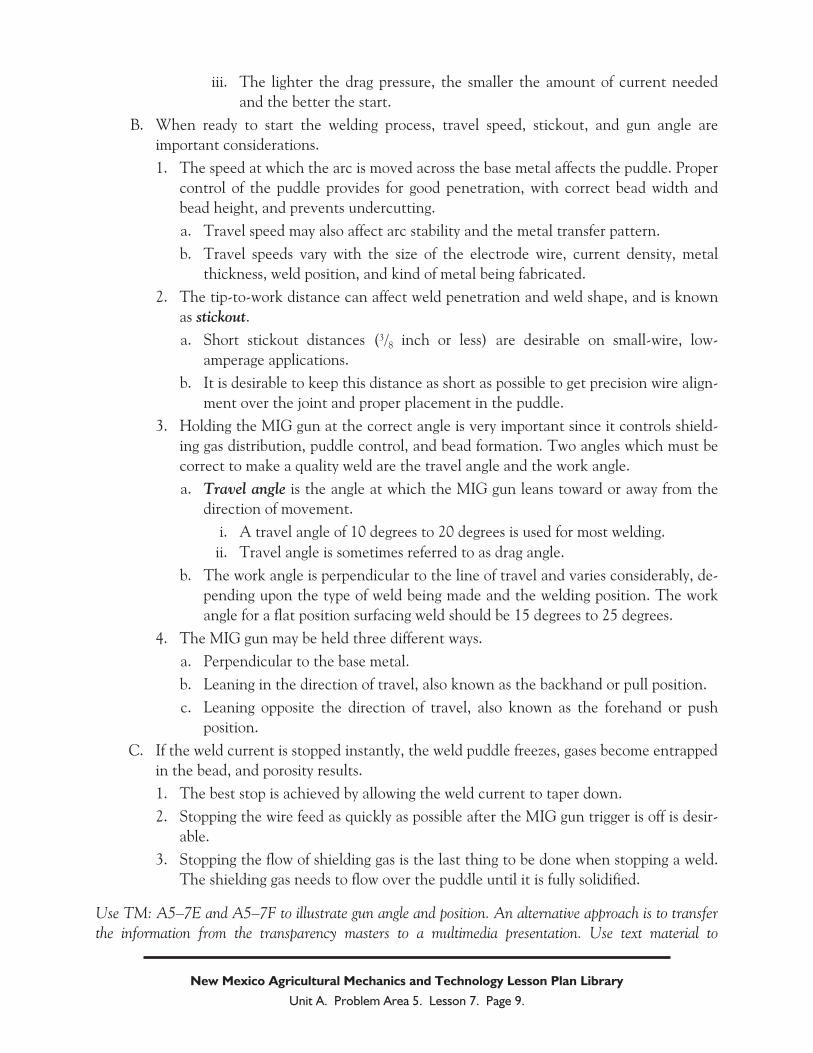
B. When ready to start the welding process, travel speed, stickout, and gun angle are
important considerations.
1. The speed at which the arc is moved across the base metal affects the puddle. Proper
control of the puddle provides for good penetration, with correct bead width and
bead height, and prevents undercutting.
a. Travel speed may also affect arc stability and the metal transfer pattern.
b. Travel speeds vary with the size of the electrode wire, current density, metal
thickness, weld position, and kind of metal being fabricated.
2. The tip-to-work distance can affect weld penetration and weld shape, and is known
as stickout.
a. Short stickout distances (3/8 inch or less) are desirable on small-wire, low-
amperage applications.
b. It is desirable to keep this distance as short as possible to get precision wire align-
ment over the joint and proper placement in the puddle.
3. Holding the MIG gun at the correct angle is very important since it controls shield-
ing gas distribution, puddle control, and bead formation. Two angles which must be
correct to make a quality weld are the travel angle and the work angle.
a. Travel angle is the angle at which the MIG gun leans toward or away from the
direction of movement.
i. A travel angle of 10 degrees to 20 degrees is used for most welding.
ii. Travel angle is sometimes referred to as drag angle.
b. The work angle is perpendicular to the line of travel and varies considerably, de-
pending upon the type of weld being made and the welding position. The work
angle for a flat position surfacing weld should be 15 degrees to 25 degrees.
4. The MIG gun may be held three different ways.
a. Perpendicular to the base metal.
b. Leaning in the direction of travel, also known as the backhand or pull position.
c. Leaning opposite the direction of travel, also known as the forehand or push
position.
C. If the weld current is stopped instantly, the weld puddle freezes, gases become entrapped
in the bead, and porosity results.
1. The best stop is achieved by allowing the weld current to taper down.
2. Stopping the wire feed as quickly as possible after the MIG gun trigger is off is desir-
able.
3. Stopping the flow of shielding gas is the last thing to be done when stopping a weld.
The shielding gas needs to flow over the puddle until it is fully solidified.
Use TM: A5–7E and A5–7F to illustrate gun angle and position. An alternative approach is to transfer
the information from the transparency masters to a multimedia presentation. Use text material to
New Mexico Agricultural Mechanics and Technology Lesson Plan Library
Unit A. Problem Area 5. Lesson 7. Page 9.
strengthen student understanding of concepts. Chapter 7 in Modern Agricultural Mechanics, Chapter 13
in Mechanics in Agriculture and Section 4 in Metal Inert Gas (MIG) Welding (VAS 3037) are recom-
mended.
Objective 5: Explain how to adjust and maintain the MIG welder.
Anticipated Problem: How is the MIG welder adjusted and maintained?
V. The MIG welder must be set correctly in order to do the best job. Machine adjustment and
maintenance are important.
A. Most MIG machines have a voltage adjustment in addition to the wire feed control.
1. Determine what the voltage should be for the kind and thickness of metal and the
shielding gas being used.
2. Fine adjustments may then need to be made so welding occurs with the right sound,
bead penetration, shape, and contour.
B. Check specifications to see what the correct gas volume should be for the weld.
1. Stand to one side of the regulator, open the tank valve completely.
2. Adjust the flowmeter to the predetermined gas volume.
3. Hold the MIG gun “on” to set to the correct operating volume.
C. Some machines have a self-contained coolant system, while others must be connected to
a water source. If it is water cooled, be sure the water is turned on.
D. The nozzle should be kept clean and free of spatter in order to properly direct the flow of
shielding gases over the puddle.
1. If filled with spatter, the nozzle may be cleaned with a nozzle reamer or a round file.
Be careful not to deform the tip while cleaning.
2. Anti-spatter dip or spray may be put on the nozzle to help prevent spatter build-up
and to make cleaning easier.
E. Contact tips need to be sized to fit the diameter of electrode wire being used.
1. The current is transmitted to the wire electrode in the contact tip.
2. Tips are usually threaded into the MIG gun so that good electrical contact is made.
Use text material to strengthen student understanding of concepts. Chapter 7 in Modern Agricultural
Mechanics, Chapter 13 in Mechanics in Agriculture and Section 6 in Metal Inert Gas (MIG) Welding
(VAS 3037) are recommended.
Objective 6: Identify safety practices that should be observed in MIG welding.
Anticipated Problem: What are the safety practices that are observed in MIG welding?
VI. The following are suggested practices and tips that will help to eliminate shop accidents
when MIG welding.
New Mexico Agricultural Mechanics and Technology Lesson Plan Library
Unit A. Problem Area 5. Lesson 7. Page 10.
A. Make sure that all welding cables and their connections are in good repair. Do not use
cables that are cracked or cut or have damaged insulation. Electrical connections on
each cable should be tight and not have frayed ends or bare wires exposed.
B. Wear welding gloves, helmet, leather apron, welding chaps, leather shoes, and other per-
sonal protective equipment to help prevent weld burns.
C. When operating a MIG welder, never touch an electrical connection, a bare wire, or a
machine part which may cause electrical shock. Never weld in damp locations because
of the shock hazard.
D. Never weld with flammables (matches, butane lighters, fuel stick, etc.) in your pockets.
E. Use pliers or tongs to handle hot metal from the MIG welding process. Never leave hot
metal where others may touch it and be burned.
F. Select the correct shaded lens for the electrode size being used. Shades 10 and 12 are
recommended.
G. Perform all welds in a well-ventilated area. Welding fumes should be ventilated away
from the weldor, not across the weldor’s face. Remember that shielding gases are
asphyxiants, and welding fumes are harmful. Work in well-ventilated areas to prevent
suffocation or fume sickness.
H. Store inert gas cylinders in a cool, dry storage area. Do not drop or abuse gas cylinders in
any way. Do not move cylinders unless the valve protection cap is in place and tight.
Check all connections with soapy water to detect leaks.
I. Hang the welding gun on a hook when it is not in use. Do not hang it on the flow meter,
regulator, or cylinder valve. Do not lay the gun on the work or worktable.
J. Protect other workers by using a welding screen to enclose your area. Warn persons
standing nearby, by saying “cover”, to cover their eyes when your are ready to strike an
arc.
K. Before starting to weld, clear the surrounding area of possible fire hazards. Remove
straw, shavings, rags, paper, and other combustible materials.
L. Be alert for fires at all times. Because the operator’s helmet is lowered, clothing may
catch fire without being noticed. Depend on your senses of touch, smell, and hearing to
indicate that something is wrong. In case of a clothing fire, strip off the article if possible.
Do not run, as running fans the flames. Wrap yourself in a fire blanket, or improvise with
a coat or piece of canvas. If there is nothing at hand to wrap in, drop to the floor and roll
slowly.
M. Protect hoses and welding cables from being stepped on or run over by vehicles. Do not
allow them to become tangled or kinked. Position them so they are not a tripping haz-
ard. Protect them from flying sparks, hot metal, or open flame, and from oil and grease
which will cause rubber to deteriorate.
N. Always unplug the welder and put all equipment away when you have finished welding
for the day.
New Mexico Agricultural Mechanics and Technology Lesson Plan Library
Unit A. Problem Area 5. Lesson 7. Page 11.
Use text material to strengthen student understanding of concepts. Chapter 7 in Modern Agricultural
Mechanics, Chapter 13 in Mechanics in Agriculture and Section 6 in Safety in the Shop (VAS 3022a)
are recommended.
Review/Summary. Focus the review and summary of the lesson around the student
learning objectives. Call on the students to explain the content associated with each objective.
Use their responses as the basis for determining any areas that need re-teaching. Questions at the
end of each chapter in the recommended textbooks may also be used in the review/summary. Use
the lab activities in reviewing and reinforcing student learning.
Application. Application can involve the following student activity using the attached lab
sheet. It is understood that before attempting the lab activities, proper safety precautions in the
agriculture mechanics shop must be covered thoroughly.
LS: A5–7A—MIG Welding Exercises
Evaluation. Evaluation should focus on student achievement of the objectives for the les-
son. Various techniques can be used, such as student performance, on the application activities. A
sample written test is attached.
Answers to Sample Test:
Part One: Matching
1 = d, 2 = f, 3 = i, 4 = a, 5 = e, 6 = b, 7 = h, 8 = j, 9 = g, 10 = c
Part Two: Completion
1. Inert gas
2. voltage, wire speed, gas flow rate
3. flux, slag, spatter
4. globular, short arc, spray transfer
Part Three: Short Answer
1. E is electrode, R is rod, 70 is 70,000 psi, S is solid bare wire.
2. Welding is faster, cleaning and preparation time is less, easy to learn, less distortion,
weld thin and thick metals, less time needed to prepare joints, can join both ferrous and
non-ferrous metals, visibility is good.
3. Too little tension results in drive wheel slippage which cause uneven feeding rate which
results in poor quality welds. Too much tension results in deformation of the wire shape
which makes it hard to thread through the unit.
New Mexico Agricultural Mechanics and Technology Lesson Plan Library
Unit A. Problem Area 5. Lesson 7. Page 12.
Sample Test Name_____________________________________
Test
Lesson A5–7: Applying Metal Inert Gas (MIG)
Welding Techniques
Part One: Matching
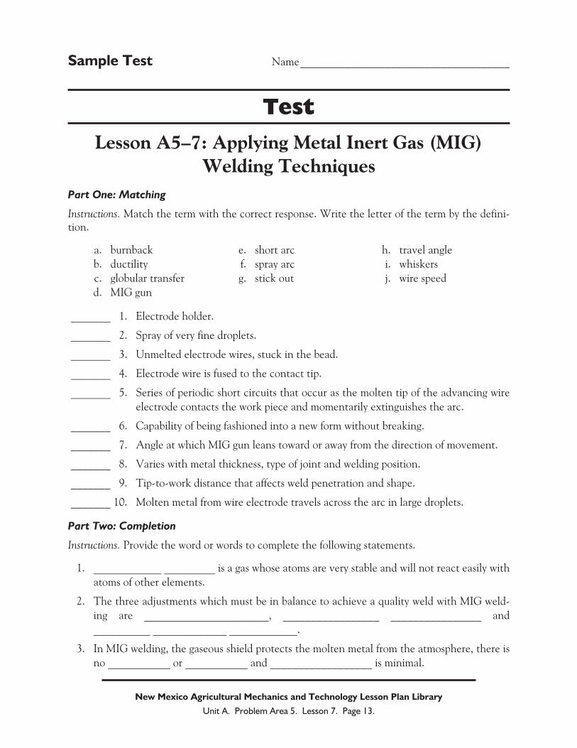
Instructions. Match the term with the correct response. Write the letter of the term by the defini-tion.
a. burnback e. short arc h. travel angle
b. ductility f. spray arc i. whiskers
c. globular transfer g. stick out j. wire speed
d. MIG gun
_______ 1. Electrode holder.
_______ 2. Spray of very fine droplets.
_______ 3. Unmelted electrode wires, stuck in the bead.
_______ 4. Electrode wire is fused to the contact tip.
_______ 5. Series of periodic short circuits that occur as the molten tip of the advancing wire
electrode contacts the work piece and momentarily extinguishes the arc.
_______ 6. Capability of being fashioned into a new form without breaking.
_______ 7. Angle at which MIG gun leans toward or away from the direction of movement.
_______ 8. Varies with metal thickness, type of joint and welding position.
_______ 9. Tip-to-work distance that affects weld penetration and shape.
_______ 10. Molten metal from wire electrode travels across the arc in large droplets.
Part Two: Completion
Instructions. Provide the word or words to complete the following statements.
1. ____________ _________ is a gas whose atoms are very stable and will not react easily with
atoms of other elements.
2. The three adjustments which must be in balance to achieve a quality weld with MIG weld-
ing are ______________________, _________________ ________________ and
__________ _____________ ____________.
3. In MIG welding, the gaseous shield protects the molten metal from the atmosphere, there is
no ___________ or ___________ and __________________ is minimal.
New Mexico Agricultural Mechanics and Technology Lesson Plan Library
Unit A. Problem Area 5. Lesson 7. Page 13.
4. In MIG welding, the metal from the wire electrode is transferred across the arc plasma to the
puddle by ______________________, _______________ ______________ or
____________ ______________ patterns.
Part Three: Short Answer
Instructions. Provide information to answer the following questions. Use complete sentences.
1. What does ER 70S6 mean or stand for?
2. What are the advantages of the MIG welding process?
3. What affect does tension have on wire feed drive wheels?
New Mexico Agricultural Mechanics and Technology Lesson Plan Library
Unit A. Problem Area 5. Lesson 7. Page 14.
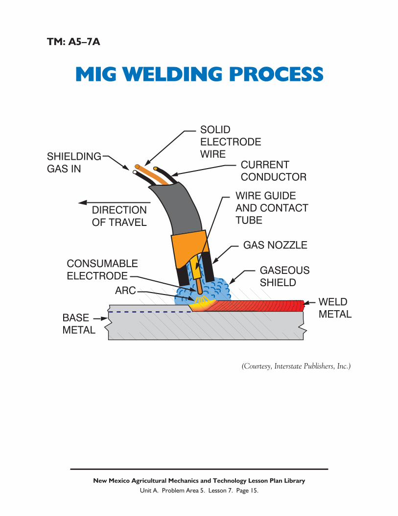
TM: A5–7A
MIG WELDING PROCESS
New Mexico Agricultural Mechanics and Technology Lesson Plan Library
Unit A. Problem Area 5. Lesson 7. Page 15.
SOLIDELECTRODEWIRE
CURRENTCONDUCTOR
WIRE GUIDEAND CONTACTTUBE
DIRECTIONOF TRAVEL
SHIELDINGGAS IN
CONSUMABLEELECTRODE
ARC
BASEMETAL
GAS NOZZLE
GASEOUSSHIELD
WELDMETAL
(Courtesy, Interstate Publishers, Inc.)
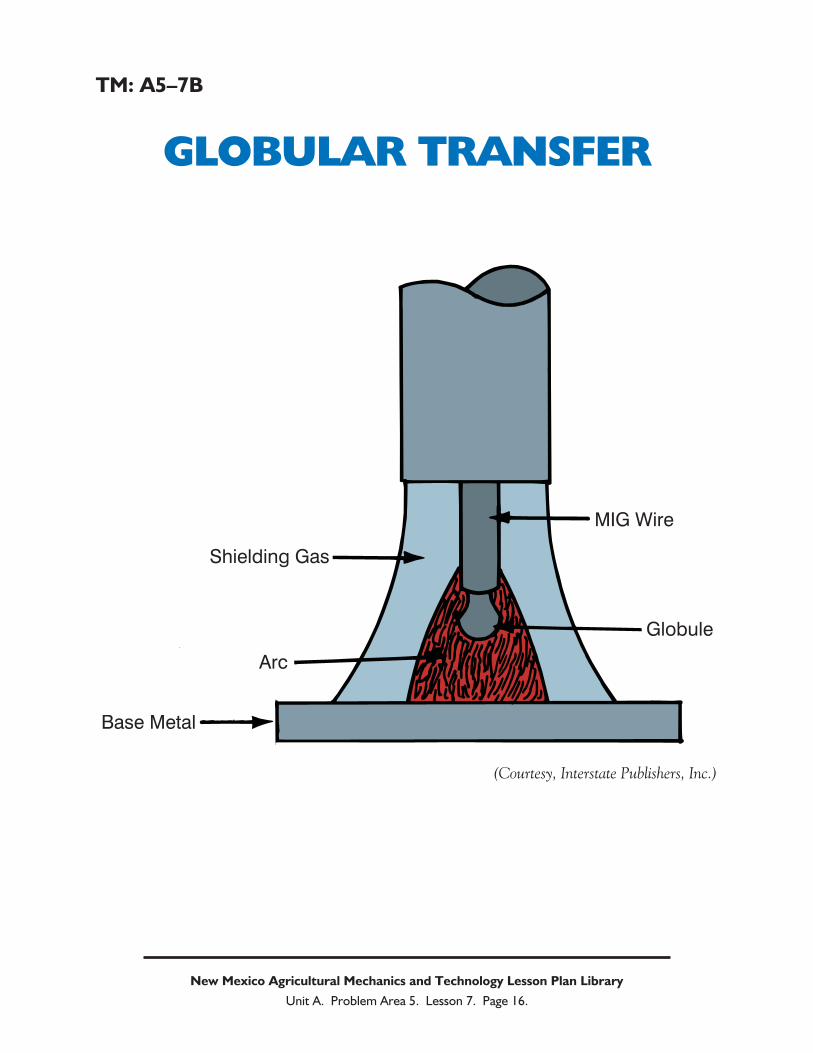
TM: A5–7B
GLOBULAR TRANSFER
New Mexico Agricultural Mechanics and Technology Lesson Plan Library
Unit A. Problem Area 5. Lesson 7. Page 16.
Shielding Gas
Arc
Base Metal
MIG Wire
Globule
(Courtesy, Interstate Publishers, Inc.)
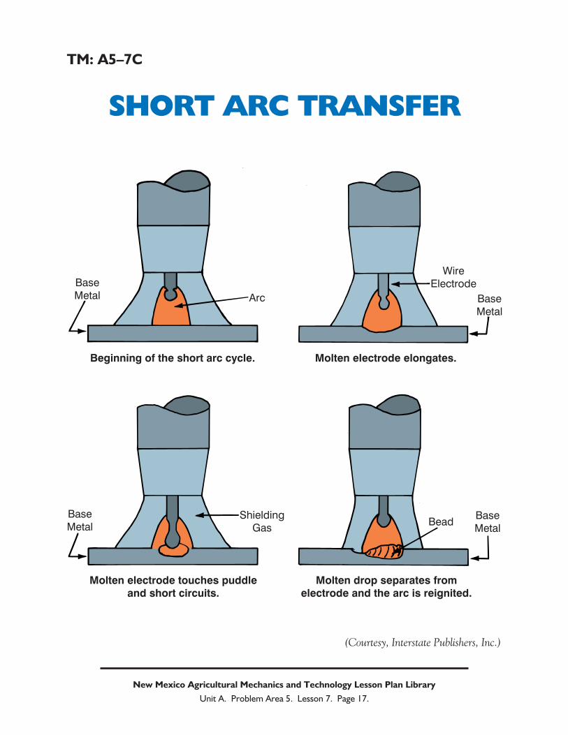
TM: A5–7C
SHORT ARC TRANSFER
New Mexico Agricultural Mechanics and Technology Lesson Plan Library
Unit A. Problem Area 5. Lesson 7. Page 17.
Base
Metal Arc
Wire
Electrode
Base
Metal
BeadBase
Metal
Shielding
Gas
Base
Metal
Beginning of the short arc cycle.
Molten electrode touches puddleand short circuits.
Molten electrode elongates.
Molten drop separates fromelectrode and the arc is reignited.
(Courtesy, Interstate Publishers, Inc.)
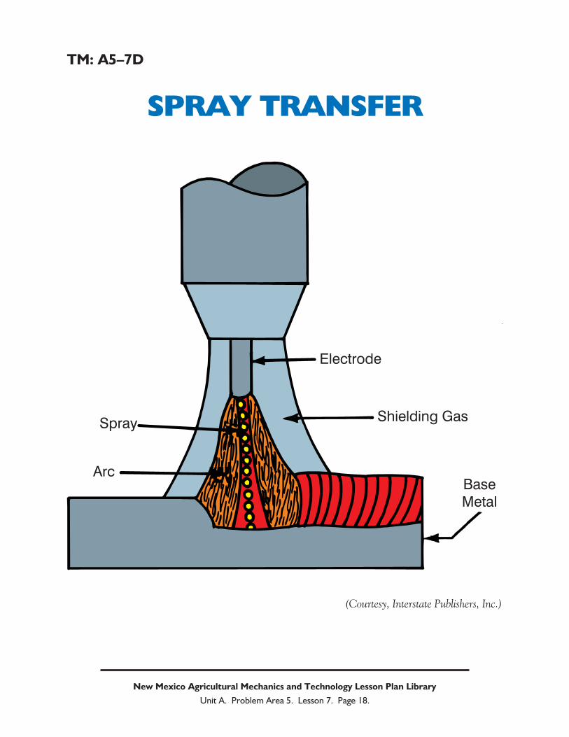
TM: A5–7D
SPRAY TRANSFER
New Mexico Agricultural Mechanics and Technology Lesson Plan Library
Unit A. Problem Area 5. Lesson 7. Page 18.
Spray
Arc
Electrode
Shielding Gas
Base
Metal
(Courtesy, Interstate Publishers, Inc.)
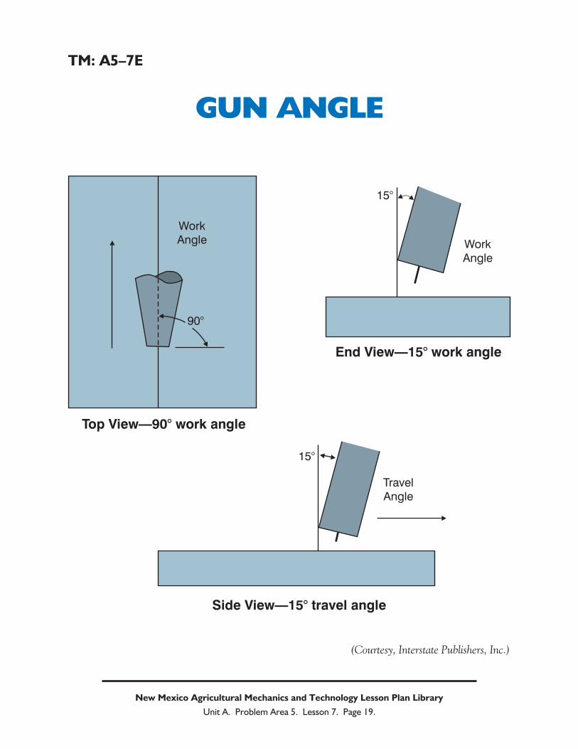
TM: A5–7E
GUN ANGLE
New Mexico Agricultural Mechanics and Technology Lesson Plan Library
Unit A. Problem Area 5. Lesson 7. Page 19.
Work
Angle
90°
15°
Work
Angle
15°
Travel
Angle
Top View—90° work angle
End View—15° work angle
Side View—15° travel angle
(Courtesy, Interstate Publishers, Inc.)
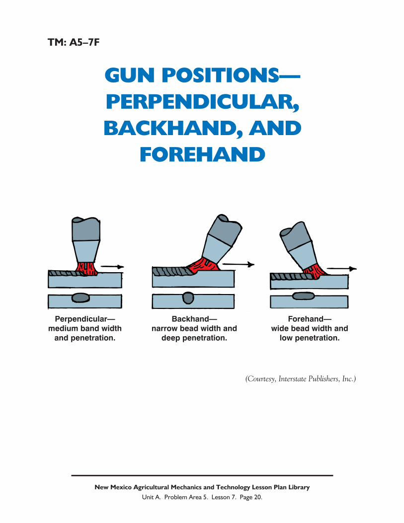
TM: A5–7F
GUN POSITIONS—
PERPENDICULAR,
BACKHAND, AND
FOREHAND
New Mexico Agricultural Mechanics and Technology Lesson Plan Library
Unit A. Problem Area 5. Lesson 7. Page 20.
Perpendicular—medium band width
and penetration.
Backhand—narrow bead width and
deep penetration.
Forehand—wide bead width and
low penetration.
(Courtesy, Interstate Publishers, Inc.)
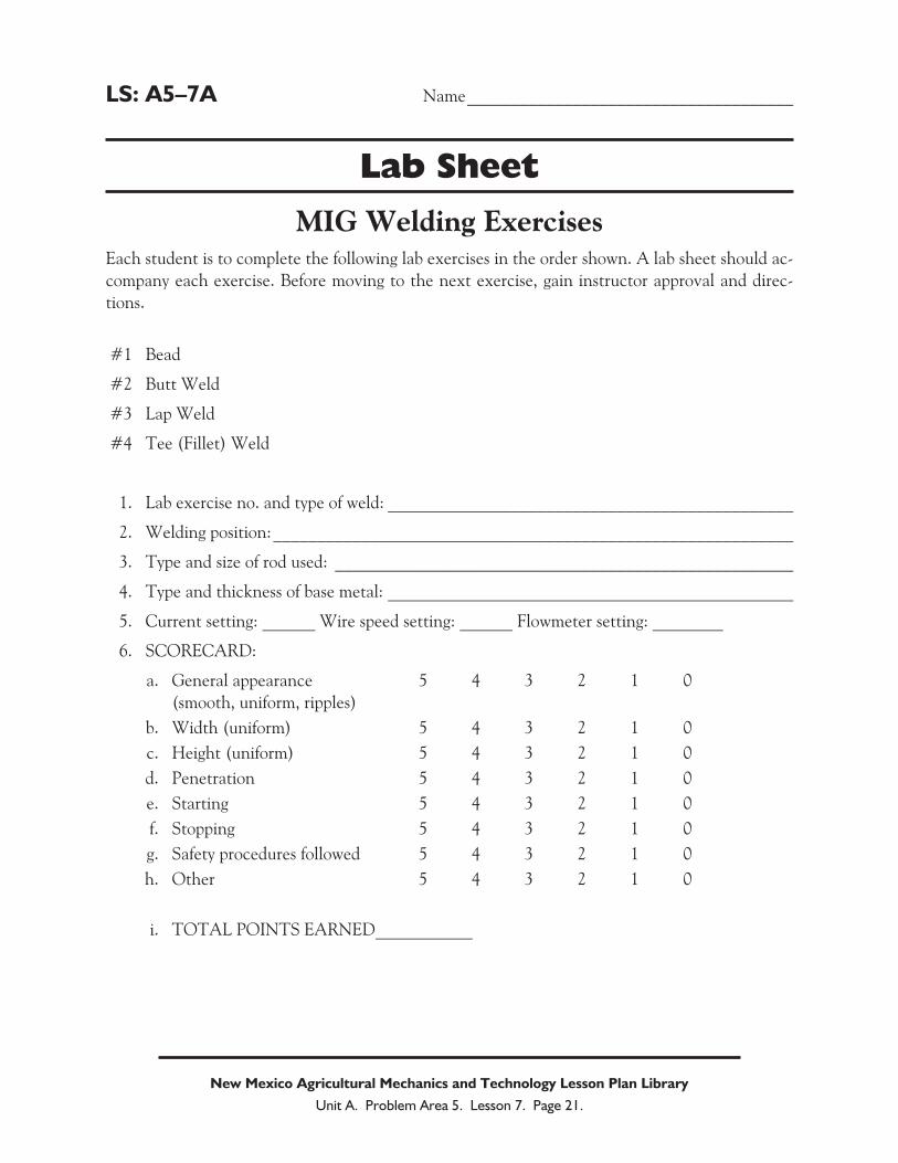
LS: A5–7A Name_____________________________________
Lab Sheet
MIG Welding ExercisesEach student is to complete the following lab exercises in the order shown. A lab sheet should ac-
company each exercise. Before moving to the next exercise, gain instructor approval and direc-
tions.
#1 Bead
#2 Butt Weld
#3 Lap Weld
#4 Tee (Fillet) Weld
1. Lab exercise no. and type of weld: ______________________________________________
2. Welding position:___________________________________________________________
3. Type and size of rod used: ____________________________________________________
4. Type and thickness of base metal: ______________________________________________
5. Current setting: ______ Wire speed setting: ______ Flowmeter setting: ________
6. SCORECARD:
a. General appearance 5 4 3 2 1 0
(smooth, uniform, ripples)
b. Width (uniform) 5 4 3 2 1 0
c. Height (uniform) 5 4 3 2 1 0
d. Penetration 5 4 3 2 1 0
e. Starting 5 4 3 2 1 0
f. Stopping 5 4 3 2 1 0
g. Safety procedures followed 5 4 3 2 1 0
h. Other 5 4 3 2 1 0
i. TOTAL POINTS EARNED___________
New Mexico Agricultural Mechanics and Technology Lesson Plan Library
Unit A. Problem Area 5. Lesson 7. Page 21.
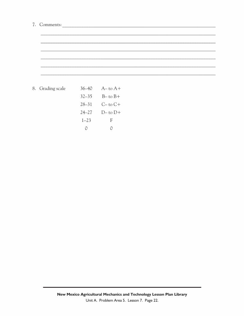
7. Comments:________________________________________________________________
_________________________________________________________________________
_________________________________________________________________________
_________________________________________________________________________
_________________________________________________________________________
_________________________________________________________________________
_________________________________________________________________________
8. Grading scale 36–40 A– to A+
32–35 B– to B+
28–31 C– to C+
24–27 D– to D+
1–23 F
0 0
New Mexico Agricultural Mechanics and Technology Lesson Plan Library
Unit A. Problem Area 5. Lesson 7. Page 22.