applied surface science - cityu.edu. · pdf fileapplied surface science 257 (2011)...
TRANSCRIPT

Applied Surface Science 257 (2011) 9158– 9163
Contents lists available at ScienceDirect
Applied Surface Science
jou rn al h om epa g e: www.elsev ier .com/ locate /apsusc
An undercutting model of atomic oxygen for multilayer silica/alumina films
fabricated by plasma immersion implantation and deposition on polyimide
Yongxian Huanga,∗, Xiubo Tiana, Shixiong Lva, Shiqin Yanga, R.K.Y. Fub, Paul K. Chub,Jinsong Lengc, Yao Li c
a State Key Laboratory of Advanced Welding and Joining, Harbin Institute of Technology, Harbin 150001, People’s Republic of Chinab Department of Physics and Materials Science, City University of Hong Kong, Tat Chee Avenue, Kowloon, Hong Kongc Center for Composite Materials and Structures, Harbin Institute of Technology, Harbin 150001, People’s Republic of China
a r t i c l e i n f o
Article history:
Received 10 May 2011
Received in revised form 30 May 2011
Accepted 30 May 2011
Available online 6 June 2011
Keywords:
Polymer
Multilayer thin films
Erosion
Plasma immersion
Monte Carlo
a b s t r a c t
Multilayer silica/alumina films were created by plasma immersion implantation and deposition to protect
against atomic oxygen (AO) in low earth orbit environment. The AO erosion mechanism of polyimide
under multilayer silica/alumina films has been investigated using a ground-based AO simulator and
Monte Carlo model. The results demonstrate that protective films are detached and plumped due to
AO undercutting, and the exterior silica film is partly detached proven by chemical composition depth
profile and erosion patterns. The undercutting model involving collision, diffusion, reaction, gas releasing,
and retroaction on films is proposed. Based on the model, scattered impingement has serious erosion,
although AO does not directly attack interior polymer. AO erosion predictions at two neighborhood cracks
are first studied by Monte Carlo model for various incidence angles of AO. The protective film between
cracks hinders the escape of AO, and accelerates the erosion.
© 2011 Elsevier B.V. All rights reserved.
1. Introduction
The low earth orbit (LEO) environment at altitudes of
200–700 km, where satellites orbit the earth, is extremely harsh
due to the presence of atomic oxygen (AO). The exposure of organic
materials such as polymer in AO environment may cause a surface
erosion rate as high as 0.5 �m per orbit [1], which can induce the
deterioration of their mechanical properties as a result of polymer
molecular destruction or polymer surface etching, and influence
service lifetime of space vehicles [2–6]. For such composites to be
used in long term space applications, they must be protected in
some manners. Owing to unique properties such as optical trans-
parency, high thermal, mechanical and high electrical resistivity
[7–10], inorganic oxide protective coatings can be used to pre-
vent or minimize surface degradation of advanced polymers and
polymer composites of LEO spacecrafts [11–14]. However, most
protective films have pinholes and defects caused by the deposition
process or substrate imperfections [15]. And the thermal expansion
coefficients of some coatings differ markedly from those of polymer
substrates, which results in cracks due to the thermal cycling after
long exposure. These cracks may provide pathways for AO to dif-
∗ Corresponding author. Tel.: +86 451 86413951; fax: +86 451 86416186.
E-mail address: [email protected] (Y. Huang).
fuse through and attack at the polymer surface resulting in erosion,
which may lead to the failure of both coating and polymer film.
It is essential to understand and negate the adverse effects of
AO erosion on spacecraft materials in order to predict performance
characteristics such as in-space durability [16–18]. However, the
prediction of in-space durability of protected organic materials has
proven to be difficult due to the lack of information concerning the
rate of in-space undercutting oxidation at defect sites in protective
coatings [16]. Predicting the AO durability in the space environment
is a very complex task complicated by the fact that material may
be sensitive to a different synergistic component in the environ-
ment. The erosion mechanisms of polymeric materials are complex
and involve initial reactions at the gas–surface interface as well
as steady-state material removal processes [19]. In this work, we
report experimental and Monte Carlo model results of AO induced
undercutting, and a key issue is to propose a model of AO induced
erosion of protective films on polymer substrate. The etching mech-
anism is indispensable for application of polymer thin films with
coating as a spacecraft construction material.
2. Experimental
2.1. Materials and preparation of samples
Experiments were performed with 100 �m thick polyimide film
(DuPontTM). Multilayer silica/alumina films were fabricated on the
0169-4332/$ – see front matter © 2011 Elsevier B.V. All rights reserved.doi:10.1016/j.apsusc.2011.05.124

Y. Huang et al. / Applied Surface Science 257 (2011) 9158– 9163 9159
Fig. 1. Characteristic erosion pattern of polyimide covered with multilayer sil-
ica/alumina films exposed to a fluence of 1.527 × 10²⁰ atoms cm−2 AO: (a) before
exposure, and (b) after exposure.
surface of polyimide using plasma ion implantation and deposition
(PIID). The aluminum and silicon plasmas were generated from the
vacuum arc using a high voltage to trigger the metal arc and a low
sustaining arc voltage between the cathode and anode. The poly-
imide samples with the size of 100 mm × 100 mm were positioned
15 cm away from the exit of the curved filtered duct, and treated in
the Al plasma for 60 min and then in Si plasma for 60 min with a neg-
ative pulse bias of 10 kV with pulse width of 150 �s and repetition
rate of 60 Hz.
2.2. AO exposure tests
Polyimide with multilayer silica/alumina films (� 40 mm)
was exposed by AO using a ground-based AO simulator, where
the AO beam with 5 eV energy and 2.02 × 10¹⁵ atoms cm−2 s−1
flux was produced using a CO2-laser detonation technology.
The longest exposure time is 21 h and the AO fluence is
1.527 × 10²⁰ atoms cm−2. A vacuum level of ∼10−3 Pa was main-
tained during AO exposure. The mass loss was measured using a
microbalance with the precision of 10−5 g. To obtain accurate mass
loss measurements, the sample was dehydrated and outgassed in
vacuum for 24 h before AO exposure.
2.3. Characterization techniques
X-ray photoelectron spectroscopy (XPS) was performed on the
Physical Electronics PHI-5600 using the monochromatic AlK� radi-
ation operated at 14 kV and 350 W. The photoelectron takeoff angle
was 45◦. The XPSPEAK software was used for peak fitting. This pro-
gram employs Newton’s method for optimization as well as Shirley
background subtraction and Gaussian–Lorentzian function for peak
fitting. The morphology of the samples before and after exposure
was examined by scanning electron microscopy (SEM). The samples
were deposited with Pt for SEM observation.
3. Results
3.1. Erosion of multilayer silica/alumina films
The SEM micrograph of multilayer silica/alumina films on a
polyimide substrate before and after exposure to AO is shown in
Fig. 1. The films were partly detached from the underlying layer
after AO exposure. In the case, the undercutting process led to “lift-
off” of the films. But the coating is crack-free even after exposure
to high fluence level. The sample with multilayer silica/alumina
Fig. 2. Chemical composition evaluated by XPS versus sputter time and thickness
of multilayer silica/alumina films on polyimide before and after AO exposure.
films showed a significantly reduced mass loss (1.06 mg/4.71 mg,
no more than quarter), compared with the polyimide control sam-
ple.
XPS was conducted to gain further insight into the chemical
changes caused by AO. Fig. 2 plots Si, Al, O, and C atomic concentra-
tion (in at.%) for multilayer silica/alumina films on the polyimide
substrate. After AO exposure, the results of higher Al and lower
Si concentrations on the surface demonstrate that the erosion of
the upper silica film has indeed occurred. Part of silica film was
peeled off, and then the downside alumina film was moved upside.
In addition, significant carbon content has been found in the mul-
tilayer films before AO exposure, which can be explained by the
presence of hydrocarbon contamination on the surface [20]. A sig-
nificant decrease of carbon content is observed after AO exposure. A
decrease of carbon concentration from 28.49% to 11.31% is detected
at 42 nm thickness. It is the reason why protective layers without
initial defects are undercut. The volatile fragments, such as short-
chain oxidation products, leave the surface of the protective layers.
As a result, the defects, such as pinholes and micro-cracks, are
formed, and then act as channels for AO to penetrate into polymer
substrate.
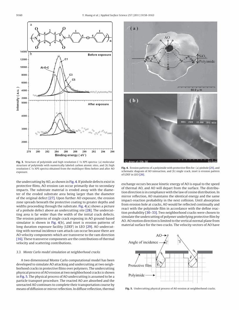
Fig. 3 shows high resolution C 1s carbon peaks for unexposed and
exposed polyimide covered with multilayer silica/alumina films.
The C 1s peak is composed of four different components: Al–O–C
at a binding energy of 283.6 eV [21,22], C1 at 284.6 eV (C–C) which
corresponds to carbon atom bonds from aromatic rings not directly
attached to the imide ring, C3 at 285.6 eV (C–N) which corresponds
to carbon atoms bonded to nitrogen, and C5 at 286.3 eV (C–O) which
corresponds to carbon atoms bonded to oxygen related to the ether
group [23–26]. The results show that there exist polymer segments
in the multilayer films. These organic components will react with
AO during exposure. Some volatile products will carry mass away
from the multilayer films, and defects are formed in the protective
film. These defects may provide pathways for AO to diffuse through
and to attack at the underlying polymer resulting in erosion.
3.2. Undercutting at the defects of protective film
Two features of AO erosion should be noticed. Firstly, for the
case without initial defects, the undercutting appears to be depen-
dent upon the organic component in the protective film as volatile
fragments leaving to form the defects, as shown in Fig. 1(b). Sec-
ondly, when some defects are existent, pathways are provided for
9160 Y. Huang et al. / Applied Surface Science 257 (2011) 9158– 9163
Fig. 3. Structure of polyimide and high resolution C 1s XPS spectra: (a) molecular
structure of polyimide with numerically labeled carbon atomic sites, and (b) high
resolution C 1s XPS spectra obtained from the multilayer films before and after AO
exposure.
the undercutting by AO, as shown in Fig. 4. If pinhole defects exist in
protective films, AO erosion can occur primarily due to secondary
impacts. The substrate material is eroded away with the diame-
ter of the eroded substrate area being larger than the diameter
of the original defect [27]. Upon further AO exposure, the erosion
zone spreads beneath the protective coating to greater depths and
widths proceeding through the substrate. Fig. 4(a) shows a picture
of a pinhole defect above an undercutting site [28]. The undercut-
ting area is far wider than the width of the initial crack defects.
The erosion patterns of single crack exposing in AO ground-based
simulator is shown in Fig. 4(b), and inset is erosion patterns of
long duration exposure facility (LDEF) in LEO [29]. AO undercut-
ting with normal incidence ram attack can occur because there are
AO velocity components which are transverse to the ram direction
[16]. These transverse components are the contributions of thermal
velocity and scattering contributions.
3.3. Monte Carlo model simulation at neighborhood cracks
A two dimensional Monte Carlo computational model has been
developed to simulate AO attacking and undercutting at two neigh-
borhood cracks in protective films over polymers. The undercutting
physical process of AO erosion at two neighborhood cracks is shown
in Fig. 5. The physical process of AO undercutting is assumed to be a
particle transport procedure. The reacted AO are absorbed and the
unreacted AO continues to complete their transportation course by
means of diffusion or mirror reflection. In diffuse reflection, thermal
Fig. 4. Erosion patterns of a polyimide with protective film for: (a) pinhole [25], and
schematic diagram of AO interaction, and (b) single crack, inset is erosion pattern
of LDEF in LEO [26].
exchange occurs because kinetic energy of AO is equal to the speed
of thermal AO, and AO will depart from the surface. The distribu-
tion direction is in compliance with the law of cosine distribution. In
mirror reflection, AO maintains the identical energy and the same
impact-reaction probability in the next collision. Until absorption
from erosion hole at cracks, AO would be reflected continually and
react with the polyimide film in accordance with the define reac-
tion probability [30–33]. Two neighborhood cracks were chosen to
simulate the undercutting of polymer underlying protective film by
AO. AO motion direction is limited to the vertical normal plane from
material surface for the two cracks. The velocity vectors of AO have
Fig. 5. Undercutting physical process of AO erosion at neighborhood cracks.

Y. Huang et al. / Applied Surface Science 257 (2011) 9158– 9163 9161
Fig. 6. Monte Carlo computational AO erosion predictions for various attack angles of AO at neighborhood cracks: (a) 0◦ , (b) 45◦ , (c) −45◦ , and (d) 45◦ and −45◦ .
random orientations and their speed distribution is Maxwellian.
Protective film will not take part in the reaction of AO and the
mean free path of AO is too large for recombination and forma-
tion of oxygen molecules. AO are driven to enter cracks and impact
the polymer cells. Oxidization effects occur and the reacted cells are
removed. Optimal values of AO interaction parameters have been
identified by forcing the Monte Carlo computational predictions
to match the results of protected samples retrieved from the LDEF
[34].
Two neighborhood cracks with width of 1 �m and 4 �m and
with distance of 5 �m were chosen to study the interaction of cracks
during AO exposure. Fig. 6 shows the Monte Carlo model computa-
tional erosion cavities, and four kinds of situations of 0◦, 45◦, −45◦
attack angles have been carried on the analysis. When AO enters,
the AO becomes somewhat trapped and has multiple opportunities
for reaction until it either reacts or escapes out the defects. When
AO fluence is low, the cracks are isolated during AO exposure, and
erosion cavities do not connected. With increasing AO fluence, the
polymer just under the protective film between cracks decreases,
and the undercutting cavities have been gradually connected. In
some extent, the protective film hinders the escape of AO, and accel-
erates the erosion. That is to say, materials not only are attacked by
AO in the line of sight of the ram fluence, but also by reflected AO.
Experiments performed by Banks et al. [35] also showed the same
effect. When the angles of incidence are 45◦ and −45◦, the interac-
tion between cracks is different owing to the neighborhood cracks
width. For the angle of 45◦, the erosion is more serious at the side of
wide crack, and erosion cavities have been communicated when the
AO fluence is only 1.923 × 10²¹ atoms cm−2. As shown in Fig. 6(d),
to simulate in-orbit service process of flight vehicle, the 45◦ angle
of AO incidence is transformed as −45◦, the erosion morphology is
more complex, and “beaker” shape disappears. Due to the interac-
tion of two neighborhood cracks, the erosion cavity width increases
with interior erosion step.
4. Discussion
The AO eroded profiles, which are far wider than the width of
the initial defects, is named the undercutting model. As shown in
Fig. 7, the basic process in the proposed model involves the colli-

9162 Y. Huang et al. / Applied Surface Science 257 (2011) 9158– 9163
Fig. 7. Schematic diagram of interaction between AO and polymer covered with protective film.
sion, diffusion of AO and reaction with polymer, forming bubble at
or below the surface of polymer, breaking of blister with gas release,
and eventual formation of crater at the polymer surface, detaching
and plumping the protective films. Initially, incidence AO enters
from defects and collides with polymer or protective film. Direct
inelastic scattering, in which only a fraction of the initial transla-
tion energy is lost to the surface, is the most probable non-reactive
interaction [19]. The reaction probability for thermally accommo-
dated AO is probably not greater than 0.003. The loss rate of AO on
the surfaces is characterized in terms of the surface loss coefficient,
= 1 − (Fout/Fin), where Fin is the incident fluence of AO onto a sur-
face and Fout is the total fluence of AO atoms leaving the surface,
from both instantaneous reflection and desorption of adsorbed AO
[36]. Greaves et al. has reported values of from 0.0001 to 0.24 for
AO on various oxide surface [37]. Most of AO scatters with sufficient
energy to break organic polymer bonds. Then, sufficient fluence
causes oxidative erosion of polymers, and significantly contributes
to the undercutting. Secondly, the chemisorption AO diffuses in
the polymer. The impinging AO can be captured by a potential
well at or below the surface where it chemically reacts to form an
oxide, which migrates from the surface into the bulk of the poly-
mer [38]. AO sticking to the surface is capable to diffuse into the
polymer to significant depths (more than 5 nm at least) before it
reacts with polymer molecules [2]. Thirdly, AO reacts with some
elements such as carbon, nitrogen, and hydrogen to form bubbles.
While the concentration of the gas builds up, the coalescence of
bubbles forms blisters [39]. Fourthly, in polymer substrate, a crater
is formed and gas is released. Meanwhile, volatile products will
carry mass away from the surface [27]. It is speculated that these
gases are released from the surface by imide ring decomposition
[38]. Lastly, the upside protective film is detached and plumped.
Just so, although AO attack on internal or interior surface may not
have direct exposure to the LEO AO fluence, scattered impinge-
ment can have serious degradation effects where sensitive interior
surface are present [29].
The results of erosion pattern and chemical composition depth
profile make sure that the undercutting model is able to explain the
erosion mechanism of AO. Based on the undercutting model, the
anti-AO erosion protective films should be multilayer and have no
or few defects. Furthermore, interface adhesion of protective film
should be high enough to avoid cracks caused by thermal cycle. Due
to the formation of complexes to increase adhesive strength, the
hybrid PIID process will be promising for fabricating the protective
film for anti-AO undercutting. Prior to ion implantation process,
nano-scale deposition coatings are needed for preventing organic
components entering protective film.
5. Conclusion
In the present study, the undercutting model of polymer covered
with protective film induced by AO was defined. The undercut-
ting model is proposed involving the collision, diffusion of AO and
reaction with polymer, forming bubble at or below the surface of
polymer, breaking of blister with gas release, and eventual forma-
tion of crater on the polymer surface, detaching, plumping and even
bursting the protective film. The established model is supported
by the results of erosion pattern and chemical composition depth
profile, and can be applied to explain the AO erosion mechanism
of polymer covered with protective film. The neighborhood cracks
are not isolated, and the undercutting cavities have been gradually
connected with increasing AO fluence. Furthermore, the protec-
tive film between cracks hinders the escape of AO, and accelerates
the erosion. The results of this study could shed more insights into
predicting the AO durability of existing polymers and fabricating
anti-AO erosion protective film for the next generation of spacecraft
materials.
Acknowledgements
The work was jointly supported by the Science and Technol-
ogy Innovation Research Project of Harbin for Young Scholar (No.
2009RFQXG050), the National Natural Science Foundation of China
(No. 50904020), and the China Postdoctoral Science Foundation
(No. 20090460883).
References
[1] J. Visentine, NASA/SIDO Space Environmental Effects on Materials Workshop,NASA Conference Publication, Hampton, 1988, p. 179.
[2] V.E. Skurat, E.A. Barbashev, Y.I. Dorofeev, A.P. Nikiforov, M.M. Gorelova, A.I.Pertsyn, Appl. Surf. Sci. 92 (1996) 441–446.
[3] R. Verker, E. Grossman, N. Eliaz, Acta Mater. 57 (2009) 1112–1119.[4] M.Z. Wang, X.H. Zhao, Z.G. Shen, S.L. Ma, Y.S. Xing, Polym. Degrad. Stab. 86
(2004) 521–528.[5] H. Shimamura, T. Nakamura, Polym. Degrad. Stab. 95 (2010) 21–33.[6] F. Awaja, J.B. Moon, S. Zhang, M. Gilbert, C.G. Kim, P.J. Pigram, Polym. Degrad.
Stab. 95 (2010) 987–996.[7] S. Mann, G.A. Ozin, Nature 382 (1996) 313–318.[8] J. Li, Y. Han, Langmuir 22 (2006) 1885–1890.[9] M. Deepa, A.K. Srivastava, S. Lauterbach, Govind, S.M. Shivaprasad, K.N. Sood,
Acta Mater. 55 (2007) 6095–6107.[10] Y.H. Choi, X. Bulliard, A. Benayad, Y. Leterrier, J.A.E. Månson, K.H. Lee, D. Choi,
J.J. Park, J. Kim, Acta Mater. 58 (2010) 6495–6503.[11] H. Shimamura, T. Nakamura, Polym. Degrad. Stab. 94 (2009) 1389–1396.[12] I.H. Tan, M. Ueda, R.S. Dallaqua, N.R. Demarquette, L. Gengembre, Plasma Pro-
cess. Polym. 4 (2007) S1081–S1085.[13] Y.X. Huang, X.B. Tian, S.Q. Yang, R.K.Y. Fu, P.K. Chu, Appl. Surf. Sci. 253 (2007)
9483–9488.

Y. Huang et al. / Applied Surface Science 257 (2011) 9158– 9163 9163
[14] M. Ueda, K.G. Kostov, A.F. Beloto, N.F. Leite, K.G. Grigorov, Surf. Coat. Technol.186 (2004) 295–298.
[15] M.D. Groner, S.M. George, R.S. Mclean, P.F. Carcia, Appl. Phys. Lett. 88 (2006)051907.
[16] K.K. de Groh, B.A. Banks, D.C. Smith, Solar Eng. 2 (1995) 939–950.[17] S.K. Rutledge, J.A. Mihelcic, Undercutting of Defects in Thin Film Protective
Coatings on Polymer Surfaces Exposed to Atomic Oxygen, 1990, NASA TM-101986.
[18] A. Snyder, K.K. de Groh, The Dependence of Atomic Oxygen Undercutting ofProtected Polyimide Kapton® H upon Defect Size, 2001, NASA-TM-210596.
[19] T.K. Minton, J.M. Zhang, D.J. Garton, J.W. Seale, High Perform. Polym. 12 (2000)27–42.
[20] G. Dennler, A. Houdayer, P. Raynaud, I. Séguy, Y. Ségui, M.R. Wertheimer, PlasmaPolym. 8 (2003) 43–59.
[21] M.C. Zhang, E.T. Kang, K.G. Neoh, C.Q. Cui, T.B. Lim, Polymer 42 (2001) 453–462.[22] Q.D. Ling, S. Li, E.T. Kang, K.G. Neoh, B. Liu, W. Huang, Appl. Surf. Sci. 199 (2002)
74–82.[23] G. Beamson, D. Briggs, High Resolution XPS of Organic Polymers: The Scienta
ESCA300 Database, Wiley, Chichester, England, UK, 1992.[24] S.H. Kim, S.H. Cho, N.E. Lee, H.M. Kim, Y.W. Nam, Y.H. Kim, Surf. Coat. Technol.
193 (2005) 101–106.[25] S.C. Park, K.J. Min, K.H. Lee, Y. Jeong, Y.B. Park, Met. Mater. Int. 17 (2011)
111–115.
[26] L.J. Matienzo, F.D. Egitto, Polym. Degrad. Stab. 35 (1992) 181–192.[27] K.K. de Groh, J.A. Terlep, T.M. Dever, Atomic Oxygen Durability of Solar-
Concentrator Materials for Space Station Freedom, 1990, NASA-TM-105378.[28] A. Snyder, B.A. Banks, D.L. Waters, Undercutting studies of protected Kapton®
H exposed to in-space and ground-based atomic oxygen, in: Proceedings of the10th ISMSE & the 8th ICPMSE, Collioure, France, SP-616, 2006.
[29] B.A. Banks, K.R.M. Sharon, K.K. de Groh, R. Demko, Atomic Oxygen Effects onSpacecraft Materials, 2003, NASA-TM-212484.
[30] B.A. Banks, K.K. de Groh, B.M. Auer, L. Gebauer, J.L. Edwards, Monte Carlo mod-eling of atomic oxygen attack of polymers with protective coatings on LDEF,AIAA 11 (1993) 282820.
[31] K. Kim, B.A. Banks, J. Spacecraft Rockets 31 (1994) 656–664.[32] B. Lin, S.L. Gao, Y. Zhao, J. Aerospace Shanghai 6 (2001) 55–59.[33] Y. Liu, G.H. Li, Acta Astronaut. 67 (2010) 388–395.[34] B.A. Banks, T. Stueber, M. Norris, Monte Carlo Computational Modeling of the
Energy Dependence of Atomic Oxygen Undercutting of Protected Polymers,1998, NASA-TM-207423.
[35] B.A. Banks, K.K. de Groh, K.R.M. Sharon, MISSE Scattered Atomic Oxygen Char-acterization Experiment, 2006, NASA-TM-214355.
[36] S. Gomez, P.G. Steen, W.G. Graham, Appl. Phys. Lett. 81 (2002) 19–21.[37] J.C. Greaves, J.W. Linnett, Trans. Faraday Soc. 54 (1958) 1323–1330.[38] M.R. Reddy, J. Mater. Sci. 30 (1995) 281–307.[39] D. He, M.N. Bassim, J. Mater. Sci. 33 (1998) 3525–3528.