applied science & technology secondary 4 … science and technology ... electrical engineering:...
TRANSCRIPT

APPLIED SCIENCE AND TECHNOLOGY
SECONDARY 4
STUDY GUIDE
2015
Version 3.0

This study guide has been developed by teachers and consultants to help students
prepare for the MELS uniform examination for the secondary 4 Science & Technology
courses. The production of this guide has been funded by an Anglophone community
success project.
Teacher Development team:
Daniela Bartus English Montreal School Board (Version 1 - 2013)
Anita Liscio English Montreal School Board (Version 1 - 2013)
Pamela Leger English Montreal School Board (Version 1 - 2013)
Sue Cristiano English Montreal School Board (Version 2 - 2013)
Anita Boray Lester B. Pearson School Board (Version 1 - 2013)
Christine Pouget Lester B. Pearson School Board (Version 1 - 2013)
Jennifer Sholzberg Lester B. Pearson School Board (Version 1 - 2013)
Patsy Gillis Lester B. Pearson School Board (Version 2 - 2013)
Amanda Sanniti Lester B. Pearson School Board (Version 2 - 2013)
Erika Stanischewski Sir Wilfrid Laurier School Board (Version 1 - 2013)
Andrea Venditti Sir Wilfrid Laurier School Board (Version 1 - 2013)
Gordon Truesdale Sir Wilfrid Laurier School Board (Version 2 - 2013)
Heather McPherson Sir Wilfrid Laurier School Board (Version 2 - 2013)
Clifford Tam Riverside School Board (Version 2 - 2013)
School Board Consultants:
Imma Ienaro English Montreal School Board
Katherine Davey Lester B. Pearson School Board
Michael Quinn Sir Wilfrid Laurier School Board
Sandra Frechette Riverside School Board
Many thanks to the members of the STIC team (Phil Ritchie, Richard Esdale, and Jan
Novak) for their contributions to the Technological World section.
Many thanks also to Julie Phenix, Susan O’Keeffe and Amanda Wilkins for their help
with the graphics and text formatting of this document.
Finally, many thanks also to Christie Brown for facilitating this project.
This document may be reproduced and distributed for educational, non-commercial
purposes only.

Table of Contents
Earth and Space ............................................................................................................ 5
Hydrosphere: Catchment Area .................................................................................... 6
Atmosphere: Cyclone and Anticyclone ...................................................................... 10
Renewable and Non-Renewable Energy Resources ................................................. 13
Concepts Related to Astronomy: Earth-Moon System ............................................... 20
Material World ................................................................... Error! Bookmark not defined.
Chemical Changes: Combustion ............................................................................... 23
Chemical Changes: Oxidation ................................................................................... 26
Electricity and Electromagnetism: Electrical Charge.................................................. 30
Electricity and Electromagnetism: Static Electricity.................................................... 34
Electricity and Electromagnetism: Ohm’s Law ........................................................... 39
Electricity and Electromagnetism: Electrical Circuits ................................................. 47
Electricity and Electromagnetism: Relationship between Power and Electrical Energy
................................................................................................................................... 60
Electromagnetism: Forces of Attraction / Repulsion .................................................. 68
Electromagnetism: Magnetic Field of a Live Wire ...................................................... 72
Electromagnetism: Magnetic Field of a Solenoid ....................................................... 78
Electromagnetism: Electromagnetic Induction ........................................................... 83
Transformation of Energy: Law of Conservation of Energy ....................................... 85
Transformation of Energy: Energy Efficiency ............................................................. 87
Fluids: Archimedes’ Principle ..................................................................................... 92
Fluids: Pascal’s Law .................................................................................................. 94
Fluids: Bernoulli’s Principle ........................................................................................ 96
Force and Motion: Force ............................................................................................ 98
Force and Motion: Types of Forces ......................................................................... 100
Force and Motion: Equilibrium of Two Forces ......................................................... 102
Force and Motion: Relationship between Constant Speed, Distance and Time ...... 104
Force and Motion: Distinction between Mass and Weight ....................................... 106

Technological World ................................................................................................. 109
Graphical Language ................................................................................................ 110
Graphical Language: Multiview Orthogonal Projection ............................................ 112
Graphical Language: Functional Dimensioning ....................................................... 117
Graphical Language: Developments ........................................................................ 119
Graphical Language: Standards and Representations ............................................ 122
Mechanical Engineering: Adhesion and Friction of Parts ......................................... 124
Mechanical Engineering: Linking of Mechanical Parts ............................................. 127
Mechanical Engineering: Guiding Control ................................................................ 134
Mechanical Engineering: Motion Transmission and Motion Transformation Systems
................................................................................................................................. 137
Mechanical Engineering: Motion Transmission Systems ......................................... 138
Mechanical Engineering: Speed Changes ............................................................... 145
Mechanical Engineering: Motion Transformation Systems ...................................... 149
Electrical Engineering: Power Supply ...................................................................... 156
Electrical Engineering: Conduction, Insulation and Protection ................................. 159
Electrical Engineering: Control ................................................................................ 163
Electrical Engineering: Transformation of Energy .................................................... 164
Electrical Engineering: Other Functions ................................................................... 169
Materials: Constraints .............................................................................................. 174
Materials: Heat Treatments ..................................................................................... 179
Materials: Types and Properties .............................................................................. 180
Materials: Modification of Properties ........................................................................ 182
Manufacturing: Characteristics of Drilling, Tapping, Threading and Bending .......... 184

EARTH AND SPACE

Earth and Space Page 6 Version 3
Hydrosphere: Catchment Area
I can define a catchment area as ‘a territory surrounding a waterway’.
Explanation of Concepts
Precipitation falls on the surface of the Earth, accumulates in streams, and infiltrates the
ground. The natural slope of the land causes water to flow into rivers and accumulate in
larger reservoirs, such as a lake. All the area from which water empties into the same
large body of water is called a catchment area or watershed.
The boundaries of a catchment area are usually defined by natural high ground, such as
a hill or peak.
A Catchment Area
Questions
Which of the following does not affect the flow of water into a catchment area? 1.
A) Depth and latitude of the water reservoir
B) Industrial and urban development
C) Shape and slope of the terrain
D) Density and diversity of the vegetation

Earth and Space Page 7 Version 3
Which location is in the same catchment area? 2.
A) 1 and 2 only
B) 1 and 3 only
C) 2 and 3 only
D) 2 and 4 only
Answers
A 1.
C 2.

Earth and Space Page 8 Version 3
Hydrosphere: Catchment Area
I can describe and interpret some of the impacts of human activity on the
waterways in a catchment area.
Explanation of Concepts
Human activity which impacts waters will not only affect the immediate area, but also
the area downstream of the disturbance.
For example, excess fertilizer from a farm can seep into the soil and be washed into a
river. The river is part of a catchment area and downstream of the farm will also be
contaminated with the fertilizer. Locations upstream from the farm will not be affected.
Water pollution can therefore spread hundreds of kilometers from its original source.
Questions
Which of the following activities has the greatest impact on the flow of water in a 1.
catchment area?
A) Filling up a child’s swimming pool with 40 L of water.
B) Treating drinking water for a city in a municipal water treatment plant.
C) Rerouting rivers for the construction of a hydroelectric dam.
D) Repairing a bridge connecting Montreal’s South Shore to the Island of Montreal.

Earth and Space Page 9 Version 3
An inspector for a town of has noticed that the wastewater for the A2A carwash has 2.
been flowing into a nearby stream. The inspector informed the A2A carwash owners
that they would be fined since they were polluting the town’s water source.
Use the map of the town’s watershed below to explain whether the inspector was
correct in fining the carwash. Explain your answer.
A2A Car Wash
Town
Water Filtration Plant
Answers
1. C
2. The inspector was correct. The A2A carwash and the town’s filtration plant are in the same catchment area
(watershed). Since the A2A car wash is above the filtration plant, any wastewater it produces will flow
downstream and enter into the river used to supply the town with drinking water.

Earth and Space Page 10 Version 3
Atmosphere: Cyclone and Anticyclone
I can explain the formation of cyclones (low-pressure areas) and
anticyclones (high pressure areas).
Explanation of Concepts
Cyclones (depressions) occur when warm air rises and leaves less air particles in the
space beneath it. This space below becomes a low pressure area called a depression.
The rising air cools and condenses and this leads to the formation of clouds.
When depressions occur, the weather is cloudy and wet.
In the Northern Hemisphere winds blow in the counter clockwise direction around
a depression.
When a depression occurs over warm tropical oceans, strong depressions occur
and tropical storms arise.
Earth and Space Page 11 Version 3
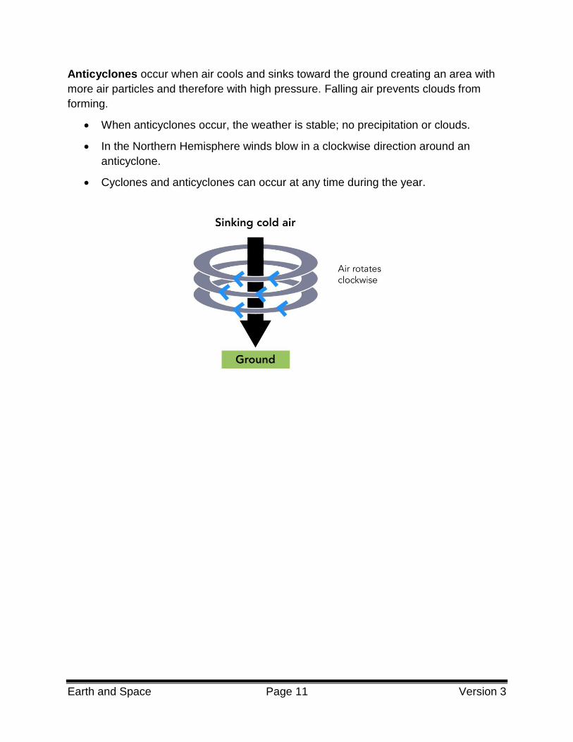
Anticyclones occur when air cools and sinks toward the ground creating an area with
more air particles and therefore with high pressure. Falling air prevents clouds from
forming.
When anticyclones occur, the weather is stable; no precipitation or clouds.
In the Northern Hemisphere winds blow in a clockwise direction around an
anticyclone.
Cyclones and anticyclones can occur at any time during the year.

Earth and Space Page 12 Version 3
Questions
A weather map is shown below. 1.
The letter H on a weather map shows an area of High pressure and the letter L
shows an area of Low pressure.
What kind of weather should people living in Region B expect?
A) Clear skies and stable weather
B) Heavy rains and winds
C) Cloudy weather and showers
D) Tropical storm
Louise and Tom are going on an overnight camping trip. According to the weather 2.
channel, a low pressure system (cyclone or depression) is on its way.
Should they bring their wet weather gear? Explain using scientific principles.
Answers
1. A
2. Yes, they should bring their wet weather gear because depressions mean cloudy and rainy weather. Warm
air is rising which encourages cloud formation.

Earth and Space Page 13 Version 3
Renewable and Non-Renewable Energy Resources
I can describe technologies used to produce electricity using the energy
resources in the lithosphere, hydrosphere and atmosphere.
Explanation of Concepts
Lithosphere
Energy Source Description
Fossil Fuels
Produced when animal and plant residues accumulate on the sea
floor and gradually get covered by layers of sand and rock. Over
millions of years, they are transformed into oil and natural gas.
Humans mine fossil fuels and burn them to produce thermal
energy, which can also be converted into mechanical and
electrical energy in thermal power plants.
The burning of fossil fuels releases pollutants such as carbon
dioxide (CO2) and methane (CH4). Other gases, such as sulfur
dioxide (SO2) and nitrogen oxides (NOX) are also released.
Uranium
(Nuclear)
Uranium is a radioactive element and exists naturally in the
lithosphere.
Nuclear power plants use mined uranium to transform thermal
energy into mechanical and electrical energy.
A small amount of radioactive material produces a lot of energy
Nuclear waste is another by-product and needs to be buried since
it continues to release radioactivity for hundreds of years
Geothermal
Below the lithosphere lies hot magma which releases thermal
energy. Harnessing this energy is called geothermics.
A fluid is circulated into the ground; it is heated naturally, then
brought up to the surface. The hot liquid can be used to heat
homes or its thermal energy can be transformed into electrical
energy.
It can be difficult to access geothermal energy. It can also be very
expensive.

Earth and Space Page 14 Version 3
Hydrosphere
Energy Source Description
Hydroelectric
Hydroelectric power plants use the movement of falling water to
spin turbines which are located inside dams built across a river.
Water falling through a dam spins a turbine that converts
mechanical energy into electrical energy.
Hydroelectricity is the main source of energy in Quebec.
Wave and
Ocean Current
Wave energy is produced when the energy contained in the
movement of water is harnessed using buoys, which rise and fall
with the waves.
Ocean currents are able to spin underwater turbines, which are
similar to wind turbines. The mechanical energy produced by the
movement of the buoys and blades can be converted into
electrical energy.
Harnessing energy from waves and ocean currents is not yet
widespread due to the fact that they are, at the moment, too
expensive.
Tidal
Electricity can be generated from tides when water from a high
tide is collected (sometimes using a dam) and then falls through
turbines converting mechanical energy into electrical energy.
A tidal range of 5 m is necessary to use this technology.
Atmosphere
Energy Source Description
Wind
The wind causes the turbines to rotate and a generator converts
the mechanical energy into electrical energy.
Wind energy cannot be stored; therefore it needs to be used in
conjunction with another source of energy.
Wind energy can be unreliable and unpredictable.

Earth and Space Page 15 Version 3
Other
Energy Source Description
Solar
As the rays of the sun hit panels containing photovoltaic cells,
they cause electrons to flow, creating current electricity.
This technology is costly and is limited by the amount of sunlight
present.
Questions
Which of the following technologies uses an energy source derived from the 1.
lithosphere?
A) Tidal barrage
B) Wind turbine
C) Photovoltaic cell
D) Coal-fired plant
The lithosphere and the hydrosphere provide us with many different resources that 2.
we can use to produce energy. Each resource has its advantages and
disadvantages.
Complete the following table regarding the advantages and disadvantages of
uranium and tidal energy:
Resource Advantages Disadvantages
Uranium
1.
2.
1.
2.
Tidal
Energy
1.
2.
1.
2.

Earth and Space Page 16 Version 3
Wind farms are growing in importance in Quebec. In partnership with Hydro-Quebec, 3.
these farms require many years of planning and construction. The Gros-Morne wind
park in the Gaspésie region will have over 140 wind turbines at the end of its
construction. In order to begin construction of Phase I in the spring of 2010,
deforestation work was performed in the fall of 2009.
What are the advantages and disadvantages of using wind energy?
Answers
1. D
2.
Resource Advantages Disadvantages
Uranium
1. small quantity of uranium will produce
much energy
2. does not produce and greenhouse
gases
1. non-renewable form of energy
2. produces radioactive waste that is toxic
to all organisms
Tidal Energy
1. renewable source of energy
2. tides are predictable; there are 2 high
tides and 2 low tides a day
1. turbines can only be used in certain
regions where tide height reaches a
minimum of 5 meters.
2. turbines are placed in harsh salt water
conditions, often far from city centers.
3. Advantages to using wind energy is that it is a renewable, clean (no greenhouse gases) form of energy.
Disadvantages to using wind energy are that the wind is not predictable and that the energy itself cannot be
stored. Some would say that the wind turbines create both visual pollution, ruining the natural beauty of the
environment and noise pollution. Deforestation also needs to take place before some wind parks are
constructed.

Earth and Space Page 17 Version 3
Renewable and Non-Renewable Energy Resources
I can describe the main impact of the use of energy resources in the
lithosphere, hydrosphere and atmosphere.
Explanation of Concepts
There are advantages and disadvantages for using the different types of energy
resources.
Note:
A non-renewable energy source is finite: It will eventually run-out or become so scarce
that it is too expensive or environmentally damaging to retrieve.
A renewable energy source is constantly replenished and will never run out.
Impact of Energy Resources from the Lithosphere
Energy
Source
Renewable or
Non-Renewable Environmental Impact
Fossil fuels Non-Renewable
The refining and burning of fossil fuels
produces atmospheric pollutants, including the
greenhouse gases carbon dioxide (CO2,
methane (CH4), and nitrogen oxides (NOx).
The burning and refining of fossil fuels can also
contribute to the production of acid rain.
Uranium
(Nuclear) Non-Renewable
No atmospheric pollutants are released.
Nuclear waste is highly toxic and must be
stored safely for hundreds of years.
Leakage of nuclear materials could have a
devastating effect.
Geothermal Renewable
Low atmospheric pollution compared to fossil
fuels.
The hot ground water used in geothermal
plants contains sulfur, mercury, hydrogen
sulfide, arsenic and ammonia. These
chemicals can be released in to the water
supply, or the atmosphere through steam.

Earth and Space Page 18 Version 3
Impact of Energy Resources from the Hydrosphere
Energy
Source
Renewable or
Non-Renewable Environmental Impact
Hydroelectric Renewable
Causes little pollution.
The building of dams often floods large areas
of land, affecting the habitat of various plant
and animal species.
Wave Renewable May disturb aquatic ecosystems.
Does not release atmospheric pollutants.
Tidal Renewable
Does not release atmospheric pollutants
Tidal barrages (dams) can interfere with fish
migration and can affect water flow and
levels.
Impact of Energy Resources from the Atmosphere
Energy
Source
Renewable or
Non-Renewable
Environmental Impact
Wind Renewable
Does not release atmospheric pollutants.
Turbines can produce sound pollution.
Can disrupt the visual appeal of the
landscape.
Birds can collide with the wind turbines.
Impact of Energy Resources from Other
Energy
Source
Renewable or
Non-Renewable Environmental Impact
Solar Renewable Does not release atmospheric pollutants.
Can disrupt the visual appeal of the
landscape.
Note: All of these technologies produce electricity by converting mechanical energy into
electrical energy except the technology associated with solar energy

Earth and Space Page 19 Version 3
Questions
A community in Gaspé is researching the environmental impacts of different energy 1.
sources.
Below is a list of possible environmental impacts
1. Tidal barrages can disrupt marine life.
2. Tidal power plants and coal power plants release greenhouse
gases.
3. Nuclear power plants create no harmful waste products.
4. Flooding is a concern in the building of hydroelectric dams.
Which of the above statements are true?
A) 1, 2 and 3 B) 1, 3 and 4 C) 1 and 4 D) 2 and 3
A community in Gaspé is researching the environmental impact of two different 2.
energy technologies: a tidal power plant and a coal power plant.
For each of the energy resources the community is considering, state:
the energy source as renewable or non-renewable
the main environmental impact for each type of energy
Answers
1. C
2. Tidal Power Plant – renewable / tidal barrages can disrupt marine life
Coal Power Plant – non-renewable / releases greenhouse gases

Earth and Space Page 20 Version 3
Concepts Related to Astronomy: Earth-Moon System
I can describe the tides in terms of the gravitational effect of the Earth-
Moon system.
Explanation of Concepts
A tide is the regular rise and fall of water in the seas and the oceans.
Bodies of water on Earth are attracted by the gravitational pull of the Sun and the Moon.
This gravitational pull causes the water masses to swell up and form a bulge twice a
day, producing tides. The size of the tides depends on the relative positions of the Sun,
Moon and Earth.
The Moon has a greater effect on the tides than the Sun.
High tides occur in locations where the side of the Earth is facing the moon. As a result
of the gravitational attraction between the Earth and the Moon, a bulge of water occurs
on the side of the earth facing the moon.
High tides also occur on the opposite side of the Earth due to rotational forces of the
Earth.
Low tides occur because the bulges of the high tides pull water away from the other
parts of the ocean, causing a depression.
As the Earth rotates on its axis, the relative position of the Moon to the Earth changes.
Therefore, most places on Earth have two high tides and two low tides every day.

Earth and Space Page 21 Version 3
Percé
Questions
A tide is the rise and fall of water in the seas and ocean. Which of the following 1.
statements are true?
1. There are two high tides and two low tides every day.
2. Tides are caused by the gravitational force of the sun.
3. The rotation of the earth causes tides
4. Tides are higher at the equator.
A) 1 and 2 B) 1 and 3 C) 2 and 4 D) 3 and 4
The circle below represents the Earth, with the location of the town of Percé 2.
indicated.
Draw a possible location of the moon when there is a high tide in Percé.
Indicate the position of the second high tide that would occur at the same time
Earth
Answers
B 1.
2.

MATERIAL WORLD

Material World Page 23 Version 3
Chemical Changes: Combustion
I can describe the recognizable manifestations of rapid combustion.
Explanation of Concepts
Rapid combustion is a form of oxidation (a reaction that uses oxygen) that releases a
large amount of energy over a short period of time. The energy is released mostly in the
form of heat and light. e.g. A candle burning.
Questions
Which of the following is NOT an example of rapid combustion? 1.
A) A log fire
B) A candle burning
C) Digestion
D) A gas stove element burning
Why is rusting classified as an oxidation reaction and not a combustion reaction? 2.
Answers
C 1.
During combustion, large amounts of heat and light are rapidly released. Rusting is an oxidation reaction that 2.
occurs at a rate too slow to be classified as combustion..

Material World Page 24 Version 3
Chemical Changes: Combustion
I can explain a combustion reaction using the fire triangle.
Explanation of Concepts
Combustion is a form of oxidation (a reaction that uses oxygen) that releases a large
amount of energy. Three conditions must be met for combustion to occur:
1) The presence of an oxidizing agent, a substance that provides oxygen to react
with a fuel
2) The ignition temperature has been reached.
The ignition temperature is the minimum temperature at which there is enough
energy to start the combustion. This varies from one type of fuel to another.
3) The presence of a fuel.
A fuel is a substance that releases a large amount of energy by reacting with an
oxidizing agent. (e.g. Wood)
Combustion will only occur if all three conditions are present. If any one of these
conditions is removed, then combustion will stop.
Examples:
Water will extinguish a fire because the water significantly reduces the temperature of
the system. (Ignition temperature not reached)
A candle will eventually stop burning when all of its wax is consumed. (Fuel no longer
present)
A frying pan fire is extinguished when a lid is placed on the pan. (Oxidizing agent
(oxygen in the air) is prevented from reaching the fuel)
Fuel Oxidizing
Agent
Ignition
Temperature
Fuel Oxidizing
Agent
Ignition
Temperature

Material World Page 25 Version 3
Questions
Firefighters use the following methods to extinguish a forest fire. 1.
Covering the ground fire with soil (shoveling)
Spraying the fire with water
Cutting down trees on the outside perimeter of the fire
Explain each of these methods by using the fire triangle.
Each year, forest fires reduce a significant area of land in Quebec to cinders. 2.
Sometimes these fires are the results of human activity but most often, they are
caused by lightning strikes.
The environmental impact of this natural phenomenon, which is part of the life cycle
of the Boreal Forests, is often widespread. In July 2005, the smoke produced by a
gigantic forest fire in northern Quebec darkened the skies as far south as the
Montreal region.
Using the terms below, explain how forest fires affect the atmosphere.
Respiration Photosynthesis The Carbon Cycle
Oxygen Carbon Dioxide Combustion
Answers
The soil prevents air (oxygen) from reaching the fire. This is an example of a decrease in the OXIDIZING 1.
AGENT.
The water absorbs heat from the fire. This is an example of preventing IGNITION TEMPERATURE.
Cutting down trees ahead of the fire means that when the fire reaches this area (a firebreak) there is less
FUEL to be burned.
Fires are a large contributor to the carbon cycle. The carbon that is in the structure of the plants being burned 2.
is being combusted using oxygen and producing high quantities of carbon dioxide. This is how Carbon
returns to the atmosphere. As a result this carbon dioxide is now available for plants to use as they undergo
photosynthesis. They use the carbon dioxide, water and the sun’s energy to make their own food. As a result
plants will grow which provides a source of food for animals. Animals will consume these plants as part of
their respiration process which involves breathing oxygen, eating plants for example and drinking water. As a
result animals are consuming carbon through the plants they eat and are releasing carbon in the form of gas
every time they exhale. It is remarkable how intertwined everything is in our ecosystem.

Material World Page 26 Version 3
Chemical Changes: Oxidation
I can represent an oxidation reaction using the particle model.
Explanation of Concepts
An oxidation reaction is a chemical reaction during which a substance reacts with
oxygen.
The particle model can be used to represent an oxidation reaction.
Symbols are used to represent the atoms involved in a chemical reaction.
The chemical reaction that follows is an oxidation reaction because it involves oxygen:
4 Fe + 3 O2 2 Fe2 O3
The number before the atom indicates the number of atoms or molecules.
For example, this equation shows 4 atoms of Fe, 3 molecules of O2 and 2 molecules of
Fe2O3.
The number to the bottom right of an atom indicates how many atoms of that kind are
bonded together in the molecule. For example, the O2 molecule contains 2 atoms of O
and the Fe2O3 molecule contains 2 atoms of Fe and 3 atoms of O.
This reaction can be represented using the particle model in the following way:
Symbols Oxygen atom: Iron atom:
+
This example represents 4 individual Fe atoms, 3 O2 molecules and 2 Fe2O3 molecules.

Material World Page 27 Version 3
Question:
Represent the following oxidation reaction using the particle model: 1.
2 Mg + O2 2 MgO
Legend
: O
: Mg
+
Answer:
1.

Material World Page 28 Version 3
Chemical Changes: Oxidation
I can associate known chemical reactions with oxidation reaction.
Explanation of Concepts
Common examples of oxidation reactions are:
Combustion
o e.g., Combustion of methane: CH4 + 2 O2 CO2 + 2 H2O
Corrosion of Metal
o e.g., Iron rusting: 4 Fe + 3 O2 2 Fe2O3
Cellular respiration:
o e.g., C6H12O6 + 6 O2 6 CO2 + 6 H2O + energy
Questions
Which of the following chemical reactions is not an oxidation reaction? 1.
A) Iron rusting: 4 Fe + 3 O2 2 Fe2O3
B) Cellular respiration: C6H12O6 + 6 O2 6 CO2 + 6 H2O + energy
C) Photosynthesis: 6 CO2 + 6 H2O + solar energy C6H12O6 + 6 O2
D) Synthesis of water: 2 H2 + O2 2 H2O
State whether or not each of the following is an example of oxidation. Explain your 2.
answer.
a) A campfire burning
b) Photosynthesis

Material World Page 29 Version 3
Answers
C: This chemical reaction does not have oxygen as a reactant and therefore does not represent an oxidation 1.
reaction
2.
a) A campfire burning is an example of an oxidation reaction. An oxidizing agent (ie oxygen) is required for
combustion to occur.
b) Photosynthesis is not an oxidation reaction. Oxygen is not required for the reaction to occur. Oxygen is
a product.

Material World Page 30 Version 3
Electricity and Electromagnetism: Electrical Charge
I understand that different particles have different charges (i.e., that a
proton has a positive charge, a neutron has neutral (no) charge and an
electron has a negative charge).
Explanation of Concepts
An atom is composed of small particles of matter: protons, neutrons and electrons. The
table below describes the charge and distribution of these elementary particles inside
the atom.
Particle Charge and Location
Particle Charge Location in atom
Proton Positive (+) Nucleus
Electron Negative (−) Electron orbitals or shells
Neutron Neutral (o) Nucleus
Electrical charge is a property of protons and electrons.
protons are positively charged (+);
electrons are negatively charged(-);
Questions
What do protons and electrons have in common? 1.
A) They both carry an electrical charge.
B) Neither of them carry an electrical charge.
C) They are both situated outside the nucleus of an atom.
D) They are both situated inside the nucleus of an atom.

Material World Page 31 Version 3
Which of the following are positively charged? 2.
1. The proton
2. The electron
3. The atom
4. The nucleus
A) 1 and 2 B) 2 and 3 C) 3 and 4 D) 1 and 4
Which of the following statements correctly describe a difference between electrons 3.
and protons?
A) Protons are found outside the nucleus; electrons are found inside the nucleus.
B) Protons are positively charged; electrons are negatively charged.
C) Protons have no electrical charge; electrons have a positive charge.
D) Protons are found inside the nucleus; electrons are found inside the neutrons
The concepts listed in the box below relate to the structure of an atom. 4.
Draw arrows to represent the correct match between each particle, its location and
its electrical charge:
a) proton 1) inside the nucleus
2) outside the nucleus
3) negative charge
4) neutral
b) electron 5) positive charge
Answers
A 1.
D 2.
B 3.
a) proton 1) and 5) 4.
b) electron 2) and 3)

Material World Page 32 Version 3
Electricity and Electromagnetism: Electrical Charge
I understand that two objects with similar electrical charges will repel each
other and that two objects with opposite electrical charges will attract each
other.
Explanation of Concepts
Brought close together, two electrically charged objects interact.
Possibility 1:
When the charges are similar, the objects repel each other
positive repels positive
negative repels negative
Possibility 2:
When the charges are opposite, the objects attract each other
positive and negative attract

Material World Page 33 Version 3
Questions
Five metallic spheres were electrically charged and then suspended as shown in the 1.
diagram below:
If sphere A is positively charged, which of the spheres are negatively
charged?
A) B and C
B) C and D
C) D and E
D) B and E
Answer
D 1.

Material World Page 34 Version 3
Electricity and Electromagnetism: Static Electricity
I can describe static electricity as the transfer of electrons from one body to
another.
Explanation of Concepts
An electrically neutral body contains the same number of protons (positive charges) as
electrons (negative charges). Protons are very tightly bound to the nucleus and cannot
be easily removed. Some electrons however, are not so tightly bound and can be
transferred from one body to another. These transfers usually occur when two bodies
are rubbed against each other.
The atom that loses electrons becomes positively charged.
The atom that gains electrons becomes negatively charged.
Electrically Charged Objects
Electrical charges can also be transferred from one body to another by direct contact.

Material World Page 35 Version 3
Questions
The list below arranges different substances in increasing order of their tendency to 1.
acquire electrons. When two of these substances are rubbed together, the one
situated lower on the list attracts electrons from the substance above and becomes
negatively charged.
Electrostatic Series Chart
Acetate Weak hold on electrons
Glass
Wool
Cotton
Ebonite
Plastic
Rubber Strong hold on electrons
In the laboratory, a student rubs a cotton cloth with each of the following materials:
ebonite, plastic, acetate and glass.
He then brings the different materials together:
1. Ebonite and plastic
2. Plastic and acetate
3. Acetate and glass
4. Glass and ebonite
In which of the situations do the materials repel each other?
A) 1 and 2
B) 1 and 3
C) 2 and 4
D) 3 and 4

Material World Page 36 Version 3
Tom wants to prepare a surprise party for his baby sister. Amongst other things, he 2.
wants to decorate the walls of their house with multi-coloured balloons. Once the
balloons are inflated, Tom rubs them on his hair for a few seconds and then sticks
them to the wall. He knows that this is possible due to friction, as the balloons
become electrically charged and are attracted to the wall.
Which of the following produced the static electricity?
A) The transfer of protons between the hair and the balloons.
B) The transfer of electrons between the hair and the balloons.
C) The transfer of electrons between the balloons and the wall.
D) The transfer of protons between the balloons and the wall.
Which of the statements below is TRUE? 3.
A) Positively charged objects have a fewer protons than electrons.
B) Positively charged objects have more electrons than protons.
C) Negatively charged objects have more electrons than protons.
D) Negatively charged objects have more protons than electrons.
A student rubbed two identical inflated balloons on a piece of fur and suspended 4.
them from a high stand. He then rubbed a plastic ruler with a piece of wool and
placed it between the two suspended balloons. The balloons quickly went high in
the air as shown in the diagrams below.
Knowing that the wool cloth transferred electrical charges to the ruler, determine the
overall charge of the balloons, fur, ruler and wool cloth. Explain your answer.

Material World Page 37 Version 3
Demonstrations using ebonite rods and wool cloth are very common in static electricity
activities. After being rubbed with wool, an ebonite rod attracts small objects. Ebonite is
known to hold its electrons very tightly when rubbed against other substances. Wool on
the other hand, exerts very weak attraction on its electrons.
The diagram below shows the distribution of electrical charges before the two
objects (ebonite rod and wool) are rubbed together:
a) Show the distribution of electrical charges in the two substances after the two
objects are rubbed together (use + and -). Explain your diagram.
b) Explain why the ebonite rod attracts small objects after being rubbed with the
wool cloth.

Material World Page 38 Version 3
Answer
B 1.
B 2.
C 3.
4.
Electrical Charge
(positive/negative)
Explanation
balloons
negative
The charges transferred from the wool to the balloons were electrons,
because only electrons can move from one atom to another. The
balloons acquired electrons and became negatively charged.
fur
positive
By transferring electrons to the balloons, the fur lost electrons and
became positively charged.
ruler
negative
Since the ruler repels the two balloons, it must be negatively charged.
By rubbing the ruler with the wool cloth, the ruler gained electrons.
wool cloth
positive
The wool cloth has transferred electrons to the ruler. Then wool cloth
lost electrons and became positively charged.
5.
a.
b. The wool cloth does not hold its electrons tightly, like the ebonite rod. By rubbing these substances
together some electrons are transferred from the wool cloth to the ebonite rod. Before being rubbed,
both objects contain equal numbers of positive and negative charges. After rubbing, the ebonite rod has
more electrons. The wool cloth has lost electrons.
NOTE: The number of negative charges that are added to the ebonite should equal the number negative
charges that were removed from the wool cloth. The number of positive charges(protons) remains the
same in both objects, because the positive charges cannot be transferred.
The ebonite rod gained electrons. When the ebonite rod is brought close to objects like small pieces of
paper and styrofoam etc, the positive charges(protons) in these objects are attracted by the electrons in
the ebonite rod. The objects will move towards ebonite rod.

Material World Page 39 Version 3
Electricity and Electromagnetism: Ohm’s Law
I can explain the relationship between voltage, resistance and current
intensity in an electrical circuit.
Explanation of Concepts
Ohm’s Law describes the relationship between current, potential difference and
resistance in a circuit.
The current intensity (I) is the amount of charge that flows through a point of an
electrical circuit in one second. (Imagine the number of the cars (electrons) passing a
point on a racetrack in one second.)
The potential difference (V) is the amount of energy provided by the power supply
(battery). It is the energy transferred by electrons between two points of an electrical
circuit. (Imagine the amount of push needed to get a car on a racetrack from point A to
point B.)
The resistance (R) of an element or a circuit is a property of materials. It is the ability of
a material to resist the flow of electric charges. (Imagine speed bumps slowing down the
cars on a racetrack.)
Relationship between Current, Potential Difference and Resistance in a Circuit
There is a proportional relationship between potential difference and current intensity for
a circuit of a given resistance.
For a circuit where the resistance is held constant,
If V ↑ then I ↑
If V ↓ then I ↓
There is an inversely proportional relationship between current intensity and resistance
in a circuit of a given potential difference.
For a circuit where the potential difference is held constant,
If R ↑ then I ↓
If R ↓ then I ↑

Material World Page 40 Version 3
There is a proportional relationship between potential difference and current resistance
for a circuit of a given current intensity.
For a circuit where the current intensity must be held constant,
If V ↑ then R must ↑
If V ↓ then R must ↓
If R ↑ then V must ↑
If R ↓ then V must ↓
Questions
In an electrical circuit, the current intensity doubles. The total resistance of the circuit 1.
stays the same.
How does the potential difference change?
A) The potential difference halves.
B) The potential difference doubles.
C) The potential difference quadruples.
D) The potential difference stays the same.
What will happen to the current intensity in an electrical circuit if, for a given 2.
resistance, the potential difference is reduced by half?
A) The current intensity will double.
B) The current intensity will not change.
C) The current intensity will reduce to half of the initial value.
D) The current intensity will quadruple.
The resistance of a circuit is increased while the current intensity is maintained at 3.
the same value. How will the voltage change? Explain why.

Material World Page 41 Version 3
Answers
B 1.
C 2.
The voltage will increase. The resistance of an electrical circuit represents the capacity of a material to 3.
oppose the flow of electrical charges. As the current intensity and voltage are directly proportional, if the
current is maintained constant and the resistance is increased, more energy will be needed for the current to
flow through the resistor, so the voltage will increase.

Material World Page 42 Version 3
Electricity and Electromagnetism: Ohm’s Law
I can use the equation (V=RI) to calculate voltage, resistance and current
intensity in an electrical circuit.
Explanation of Concepts
The mathematical expression of Ohm’s Law shows the direct proportionality between
the potential difference and current intensity, for a given resistance:
The above formula can be also written as:
or
where:
V is the potential difference (voltage) expressed in Volts (V)
I is the current intensity expressed in Amperes (A)
R is the resistance expressed in Ohms (Ω)
Using Ohm’s Law to Calculate Resistance
The graph and table below show the relationship between the potential difference and
the current intensity for the circuits of two different appliances. What is the resistance of
the circuit for each appliance?
Relationship between Potential Difference and Current
I
V R
R
V I
Appliance
Potential
Difference
(V)
Current
Intensity
(A)
A 20 10
B 10 10
V = R∙I
Pote
ntial D
iffe
rence (
V)
Current Intensity (A)

Material World Page 43 Version 3
To calculate resistance, use Ohm’s Law, V = RI
Rewrite the equation to
solve for R
Substitute in known
values.
Remember the units.
Appliance A
Appliance B
Solve for R R = 2 Ω R = 1 Ω
I
VR
A10
V20R
A10
V10R

Material World Page 44 Version 3
Questions
In the circuit diagram below the reading on voltmeter is 12 V and the reading on the 1.
ammeter is 0.6 A.
What is the resistance of element R?
A) 0.05 Ω
B) 7 Ω
C) 10 Ω
D) 20 Ω
What is the potential difference of a circuit if the resistance is 25 Ω and the current 2.
intensity is 10 A?
A) 250 Ω
B) 0.40 V
C) 2.5 V
D) 250 V
A large flashlight that requires a 1.5 V battery. If the resistance of the light bulb is 3.
3Ω, what is the current flowing through the light bulb?
A) 0.50 A
B) 1.5 A
C) 2.0 A
D) 4.5 A

Material World Page 45 Version 3
The graph below shows the variation in the current intensity, I, as a function of the 4.
potential difference (voltage), V, across a resistor.
Relationship between Potential Difference and Current
What is the resistance, R, of the resistor?
A) 0.05 Ω
B) 1 Ω
C) 5 Ω
D) 20 Ω
In the laboratory, a student was asked to measure resistance and potential 5.
difference in an electrical circuit. The circuit requires 0.5 A of current to function
optimally. He has experimented with four different resistors and recorded the data in
the table below.
Resistance and Potential Difference Values
Resistor Resistance
(Ω)
Potential Difference
(V)
1 60 12
2 24 12
3 48 12
4 36 12
Which resistors could be used for the optimal functioning of the circuit?

Material World Page 46 Version 3
Answers
D 1.
D 2.
B 3.
A 4.
Resistor 2. It provides the optimal amount of current for this circuit. 5.
Resistor 1:
Resistor 2
Resistor 3:
Resistor 4:
R
VI
60
V12 I
A0.2 I
R
VI
24
V12 I
A0.5 I
R
VI
A0.25 I
R
VI
36
V12 I
A0.3 I

Material World Page 47 Version 3
Electricity and Electromagnetism: Electrical Circuits
I can describe the function of different components of an electrical circuit.
Explanation of Concepts
Electrical circuits transform electrical energy into other forms of usable energy (light,
heat, sound, mechanical energy etc). The table below describes some components of
electrical circuits and their specific role.
Basic Electrical Circuit Components and their Functions
Component(s) and
Symbol
Electrical
Function Description
Power source,
battery Power Supply
Creates a potential difference;
transfers energy to electrons
Wires Conduction
Connect the circuit components and
the power supply; carry electrons from
the source to the components and
back to the source
Resistor
Light
Motor
Electrical
Resistance
Limit the flow of electrons; transform
electrical energy into other forms of
energy (light, heat, sound, motor etc)
Switch
Control
Allows the control of current by
connecting or breaking the circuit;
(when a switch is off, the electron flow
is interrupted)
Ammeter
N/A Measures the current flowing through
a circuit (connected in series)
Voltmeter
N/A
Measures the potential difference
(energy) that electrons have between
two points of the circuit (connected in
parallel)

Material World Page 48 Version 3
Questions
In which of the following electrical circuits is electron flow NOT possible? 1.
A) 1 and 2
B) 1 and 3
C) 2 and 3
D) 2 and 4
Which of the components depicted by the symbols below is used to STOP the 2.
electron flow in an electrical circuit?
A)
B)
C)
D)

Material World Page 49 Version 3
Match the components below with the right function they carry in electrical circuits: 3.
Functions Components
1. converts electrical energy into other forms of
energy
A ammeter
2. provides the energy to the circuit B resistor
3. controls the current C light bulb
4. measures the current intensity D voltmeter
5 measures the voltage E power supply
6. carries the current F switch
7. component that generates light G wires
Answers
D 1.
D 2.
1.B, 2.E, 3.F, 4.A, 5. D, 6. G, 7 C. 3.

Material World Page 50 Version 3
Electricity and Electromagnetism: Electrical Circuits
I can identify the two main types of electrical circuits (series, parallel).
Explanation of Concepts
In an electrical circuit electrical charges flow continuously. In order for charges to
flow, all parts of the circuit must be connected together.
Series Circuits
In a series circuit, elements are linked directly together (connected end to end). All
charges follow the same pathway. If a part of the circuit is open or an element is
defective, the current stops flowing through the entire circuit.
Parallel Circuits
A parallel circuit branches out at least at one point. The charges follow different
pathways. If part of one pathway or branch in a parallel circuit is open or an element is
defective, the current continues to flow through the other branches.

Material World Page 51 Version 3
Measuring Instruments
Ammeters are connected IN SERIES (the current passes through the ammeter).
Voltmeters are connected IN PARALLEL (outside the element whose voltage is
measured).
Questions
The diagram below shows a circuit made of two light bulbs, two switches and a 1.
power source.
Which of the following statements about this circuit is TRUE?
S1 S2 L1 L2
A) Opened Closed Off On
B) Closed Opened On Off
C) Opened Closed On Off
D) Closed Opened Off On

Material World Page 52 Version 3
Which of the circuits below are connected in parallel? 2.
1)
2)
3)
4)
A) 1 and 4
B) 2 and 4
C) 1 and 3
D) 2 and 3
In the three circuits below, if S1 is closed and S2 is open, which light bulb(s) will light 3.
up?
Circuit 1 Circuit 2 Circuit 3

Material World Page 53 Version 3
Answers
B 1.
B 2.
Circuit 1: light bulb 1 will light up 3.
Circuit 2: neither light bulb will light up
Circuit 3: light bulb 2 will light up

Material World Page 54 Version 3
Electricity and Electromagnetism: Electrical Circuits
I can explain the differences between alternating and direct current.
Explanation of Concepts
An electric current is an orderly flow of electrical charges. There are two types of
electric current:
Direct Current (DC)
Electrons continuously move in the same direction. Batteries produce DC current.
Alternating Current (AC)
Electrons change direction many times every second (they flow back and forth). AC
current is provided by an electric outlet.
Questions
Which of the following statements describe an alternating current (AC)? 1.
A) It is produced by a battery
B) Electrons change direction continuously.
C) The electrons do not move.
D) Electrons move in the same direction.

Material World Page 55 Version 3
The diagram below shows the charges inside a wire. 2.
a) Use arrows to show the motion of the electrons if this wire was part of a circuit
that had a battery as a power supply.
b) Draw a second wire with charges to show the motion of electrons if the wire was
part of a circuit that is connected to an electrical outlet.
Answers
B 1.
2.
a.
All arrows must point in the same direction
Originate ONLY with the electrons
b.
Arrows point in both directions
Originate ONLY with the electrons

Material World Page 56 Version 3
Electricity and Electromagnetism: Electrical Circuits
I can represent a simple electrical circuit using a diagram and appropriate
symbols.
Explanation of Concepts
A simple electrical circuit contains at least the following components:
a power source
components (resistors, light bulbs, motors, heating elements)
wires
a switch
Circuits are represented by precise diagrams. Certain symbols are used to represent
the elements of an electrical circuit:
Electrical Circuit Symbols
Wire Power
Supply Resistor Light Bulb Switch Ammeter Voltmeter

Material World Page 57 Version 3
Series Circuit
The figure below represents a series circuit consisting of a power supply (electrical
battery) and two resistors (light bulbs) along with its representation using symbols, in an
electrical diagram:
Circuit Circuit Diagram
Parallel Circuit
The figure below represents a parallel circuit consisting of a power supply (electrical
battery) and two resistors (light bulbs) along with its representation using symbols, in an
electrical diagram:
Circuit Circuit Diagram

Material World Page 58 Version 3
Questions
The figure below represents an electrical circuit containing a power source, two 1.
electrical bulbs and one resistor connected in parallel:
Which of the circuit diagrams below best represents this circuit?
The electrical circuit below contains two resistors, two light bulbs, a power supply 2.
and a switch - all connected by copper wires as shown in the figure below.
Draw a diagram of this circuit using appropriate symbols used in electricity. Show
the flow of charges on your diagram.

Material World Page 59 Version 3
An electrical circuit is made of two resistors connected to a power supply, an 3.
ammeter and a voltmeter. All circuit components (resistors) are connected in
parallel. The ammeter measures the current in both resistors. The voltmeter
measures the potential difference of the first resistor only.
Draw the circuit diagram, indicating also the measuring instruments.
Answers
B 1.
2.
3.

Material World Page 60 Version 3
Electricity and Electromagnetism:
Relationship between Power and Electrical Energy
I understand the relationship between power, voltage and current intensity.
I can use the equation P= VI to calculate power, voltage and current
intensity in an electrical circuit.
Explanation of Concepts
Electrical power is the amount of work an electrical device can perform in one second.
The electrical power of a circuit is directly proportional to both voltage and current
intensity and can be expressed in a formula as:
where:
P is the electrical power expressed in watts (W)
V is the voltage (potential difference) expressed in volts (V)
I is the current intensity expressed in amperes (A)
Remember: 1000 W = 1 kW
P = V I

Material World Page 61 Version 3
Questions
A student was asked to assemble a simple electrical circuit made of a resistor and a 1.
battery, an ammeter and a voltmeter. The diagram below represents the circuit that
he assembled:
The ammeter reads is 0.80 A and the voltmeter reads 20 V.
What is the electrical power of this circuit?
A) 0.040 W
B) 16 W
C) 6 W
D) 25 W
What is the current drawn when a kettle with a power of 1.65 kW is connected to a 2.
110V power supply?
A) 0.0150 A
B) 1.50 A
C) 15.0 A
D) 66.7 A
What is the voltage required by an electric grill with a power of 2.2 kW and current 3.
20 A?
A) 0.11 V
B) 9.1 V
C) 26 V
D) 110 V

Material World Page 62 Version 3
In the electrical circuit represented below, the voltage is 100 V and resistor R has a 4.
value of 50 Ω.
Calculate the electrical power of resistor R. Show all your work.
Answers
B 1.
C 2.
D 3.
Find current intensity: 4.
Find electrical power:
P= V·I P= 100 V ·2 A · P = 200 W
Answer: The electrical power of the resistor is 200 W
R
VI
50
V100 I
A2 I

Material World Page 63 Version 3
Electricity and Electromagnetism:
Relationship between Power and Electrical Energy
I can explain the relationship between the power of an electrical appliance,
the electrical energy it consumes and the amount of time it is in operation.
Explanation of Concepts
The electrical energy consumed by an electrical appliance is directly proportional to
the power of the appliance and the amount of time it is in operation.
The more powerful an electrical appliance is, the more energy it consumes for a
period of time.
The longer an appliance is in operation, the more energy it consumes.
Questions
Which of the following would reduce the cost of using an electrical appliance? 1.
1. Increase the operation time.
2. Use an appliance with a lower power rating.
3. Reduce the operation time.
4. Use an appliance with a higher power rating.
A) 1 and 3 B) 1 and 4 C) 2 and 3 D) 3 and 4
Lynn wants to buy a new hair dryer. The store sells two different models. The rating 2.
plates of the two appliances are shown below:
Model 1 Model 2
120 V 60 Hz 1200 W (1.2kW)
120 V 60 Hz 1400 W (1.2kW)
She usually dries her hair for about 15 minutes daily and she would like to use the
least amount of energy possible.
Which of the two models should Lynn buy? Explain your answer.

Material World Page 64 Version 3
Answers
C 1.
Lynn should buy Model 1. 2.
The power rating of Model 2 is lower. Since the amount of energy consumed by an appliance is directly
proportional to its electrical power, for the same amount of operating time this model is going to use less
energy.

Material World Page 65 Version 3
Electricity and Electromagnetism:
Relationship between Power and Electrical Energy
I can use the equation E = PΔt to calculate the electrical energy consumed,
the power of an electrical appliance and the amount of time it is in
operation.
Explanation of Concepts
The electrical energy of an electrical circuit can be calculated using the formula:
where:
E is the electrical energy expressed in joules (J) or kilowatt hour (kWh)
P is the electrical power expressed in W (watt) or kilowatt (kW)
t is the time interval expressed in seconds (s) or hours (h)
Remember:
Since P is calculated as VI, energy can also be solved as: E = VI ∆t
1000 J = 1 kJ
In questions where the answer is in Joules, you will use time measured in
seconds
In questions where the answer is in kWh, you will use time measured in hours
(and energy will be measured in kW)
Questions
How much energy does an electric heater with a power of 200 W consume in 2.0 1.
minutes?
A) 0.010 kJ
B) 24 kJ
C) 100 J
D) 400 J
E = P ∆t

Material World Page 66 Version 3
How much energy is consumed by an oven with an electrical power of 4000 W in 2.
use for 2.5 hours?
A) 10 kWh
B) 10 000 kWh
C) 1600 kWh
D) 1.6 kWh
How long does it take for a kettle with a power of 2 000 W to use 30 000 J of 3.
energy?
A) 15 s
B) 15000 s
C) 15 min
D) 15 h
What is the power of an electric bulb that gives off 3600 J of energy in 10 minutes? 4.
A) 6.0 kW
B) 2.8 kW
C) 6.0 W
D) 360 W
A water heater has a resistor working with a potential difference of 220 V and a 5.
current of 50 A.
Calculate the energy consumed by this water heater in 30 minutes. Show all your
work.

Material World Page 67 Version 3
Answers
B 1.
A 2.
A 3.
C 4.
Calculate the power of the resistor: 5.
P = VI P = 220 V x 50 A P = 11 000 W = 1.1 kW
Express the time in hours:
Calculate the energy consumed by the resistor:
E= P ∆t E = 11 kW x 0.5 h E = 5.5 kWh
Answer: The resistor uses 5.5 kWh of energy in 30 minutes.
** Please note the equivalent answer in Ws is 20 700 000 Ws **
min 60
h 1 min 30t
h 0.5t
Material World Page 68 Version 3
Electromagnetism: Forces of Attraction / Repulsion
I understand that for magnets, different poles attract, while similar poles
repel.
I can describe and interpret the magnetic field of a magnet and behaviour
of a compass in the magnetic field of a magnet.
Explanation of Concepts
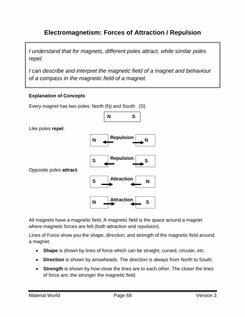
Every magnet has two poles: North (N) and South (S)
Like poles repel.
N Repulsion
N
S Repulsion
S
Opposite poles attract.
S Attraction
N
N Attraction
S
All magnets have a magnetic field. A magnetic field is the space around a magnet
where magnetic forces are felt (both attraction and repulsion).
Lines of Force show you the shape, direction, and strength of the magnetic field around
a magnet.
Shape is shown by lines of force which can be straight, curved, circular, etc.
Direction is shown by arrowheads. The direction is always from North to South.
Strength is shown by how close the lines are to each other. The closer the lines
of force are, the stronger the magnetic field.
N S
S
S

Material World Page 69 Version 3
Example: Magnetic Field of a Bar Magnet
Example: Magnetic Field of a Horseshoe Magnet
A compass needle is a free moving magnet. The North pole of the compass needle is
attracted to the South pole of a magnet. The compass needle will position itself parallel
to the field lines that are beneath it.
The behaviour of a compass in the magnetic field of a bar magnet is shown below.
Geographic north attracts the north of a compass needle. This means that magnetically
speaking, geographic north is really a magnetic south pole.

Material World Page 70 Version 3
Earth’s Magnetic Field
Image modified from http://commons.wikimedia.org/wiki/File:Earths_Magnetic_Field_Confusion.svg Retrieved
January 2014
Questions
Which of the following correctly illustrates the behavior of a compass in the magnetic 1.
field of a bar magnet?
A)
B)
C)
D)
N S
N S
N S
N S

Material World Page 71 Version 3
Indicate which pole is the North pole of the magnet. Draw the field lines. 2.
a)
b)
Answers
B 1.
2.
a.
b.

Material World Page 72 Version 3
Electromagnetism: Magnetic Field of a Live Wire
I can describe and interpret the magnetic field produced by a current-
carrying wire (right-hand rule or left-hand rule).
Explanation of Concepts
A straight wire with a current flowing through it has a circular magnetic field around it.
The magnetic field is represented by circular lines around the wire.
The magnetic field of a straight conductor can be determined using the Right Hand
Rule:
Using your RIGHT hand, point your thumb towards the negative end of the wire
(the direction of the current).
Your fingers wrap around the wire and the curl of your fingers show the direction
of the magnetic field.

Material World Page 73 Version 3
When a compass is placed in the magnetic field, the north end of the compass will point
in the direction of the magnetic field.
Questions
Which of the following diagrams correctly represents the behavior of a compass in 1.
the magnetic field of a live wire?
A)
B)
C)
D)

Material World Page 74 Version 3
A compass (shown as a circle below) is placed on a paper which has a live wire 2.
going through it. Place an arrow on the compass showing the direction in which the
compass will point.
Answers
B: When using the right hand rule, the thumb points in the direction of the conventional current. The thumb 1.
will therefore point towards the negative terminal and the fingers will wrap around the wire. The direction of
the magnetic field is shown by the direction of the fingers.
2.

Material World Page 75 Version 3
Electromagnetism: Magnetic Field of a Live Wire
I can identify ways of modifying the intensity of the magnetic field produced
by a current-carrying wire (type of wire, current intensity).
Explanation of Concepts
To increase the intensity of the magnetic field of a live wire (wire with electric current
running through it),
Increase the current intensity.
Use a better conductor.
Remember: Metals are conductors. Some metals are better conductors than
others
Examples of good conductors: gold, silver, copper
Examples of poor conductors: nichrome
Questions
An electrical engineer is trying to figure out how to maximize the intensity of a 1.
magnetic field generated from a live wire. Which scenario should she choose?
A) A copper wire with 5 A.
B) An aluminum wire with 5 A.
C) A copper wire with 10 A.
D) An aluminum wire with 10 A.
You are trying to increase the strength of the magnetic field around a current 2.
carrying wire. You have a choice between using a copper and a nichrome wire.
Which one would you use? Explain your answer.
Answers
C: A combination of copper and a strong intensity make for a good conductor 1.
I would choose a copper wire, because copper is a better conductor than nichrome. 2.

Material World Page 76 Version 3
Electromagnetism: Magnetic Field of a Live Wire
I can compare the behaviour of a compass in the magnetic field of a
magnet with that of a current-carrying wire.
Explanation of Concepts
Recall: The magnetic field lines travel from the magnetic N pole to the S pole. The lines
are drawn out of the North end and into the South end.
For a bar magnet, the behavior of the compass is shown below:
The behaviour of a compass in the magnetic field of a current-carrying wire is shown
below:

Material World Page 77 Version 3
Question:
Which of the statements below is TRUE? 1.
A) When a compass is placed in the magnetic field of a magnet, the North end of
the compass always points to the North pole.
B) When a compass is placed in the magnetic field of a magnet, the North end of
the compass always points to the South pole.
C) When placed in the magnetic field of a current carrying wire, the compass will
point towards the positive end of the wire.
D) When placed in the magnetic field of a current carrying wire, the compass will
point towards the negative end of the wire.
.
Answers
B 1.
Material World Page 78 Version 3
Electromagnetism: Magnetic Field of a Solenoid
I can interpret the magnetic field produced by a solenoid (right-hand rule or
left-hand rule).
Explanation of Concepts
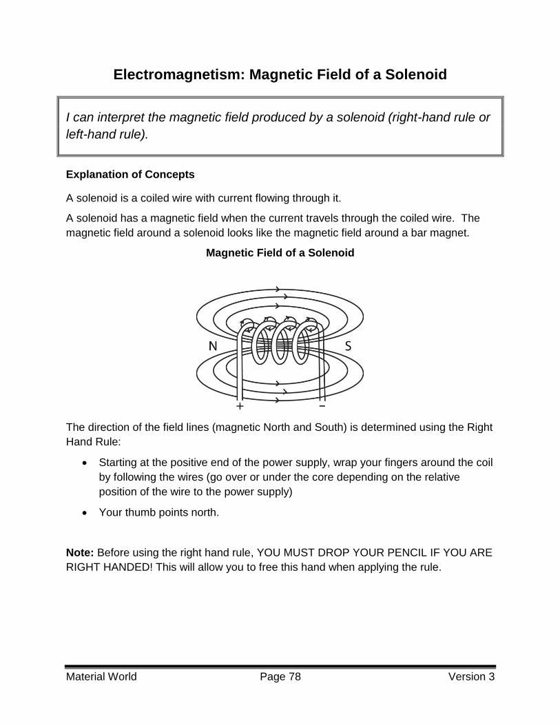
A solenoid is a coiled wire with current flowing through it.
A solenoid has a magnetic field when the current travels through the coiled wire. The
magnetic field around a solenoid looks like the magnetic field around a bar magnet.
Magnetic Field of a Solenoid
The direction of the field lines (magnetic North and South) is determined using the Right
Hand Rule:
Starting at the positive end of the power supply, wrap your fingers around the coil
by following the wires (go over or under the core depending on the relative
position of the wire to the power supply)
Your thumb points north.
Note: Before using the right hand rule, YOU MUST DROP YOUR PENCIL IF YOU ARE
RIGHT HANDED! This will allow you to free this hand when applying the rule.

Material World Page 79 Version 3
Questions
A compass is placed at one end of a solenoid. In which illustration is the compass 1.
needle pointing in the correct direction?
Which of the following correctly represents the shape of the magnetic field around a 2.
solenoid?

Material World Page 80 Version 3
Determine the direction of the current of the wire shown below: 3.
Determine whether the magnetic fields of the following two solenoids will appear to 4.
attract or repel.
Answers
D: We can determine that the solenoid will have its north end on the left and south end on the right. We can 1.
therefore conclude that the compass' north end will be attracted to the south side of the solenoid.
D: The only diagram that resembles a bar magnet. 2.
3.
-
The magnetic field of the two solenoids will look like to bar magnets that are attracting one another, North to 4.
South

Material World Page 81 Version 3
Electromagnetism: Magnetic Field of a Solenoid
I can name ways of changing the intensity of the magnetic field produced
by a solenoid (nature of the core, intensity of the current, number of turns).
Explanation of Concepts
The intensity of the magnetic field produced by a solenoid is affected by these factors:
The Nature of the Core When a ferromagnetic core is inserted in the centre of a
solenoid, the magnetic field of the solenoid is increased. A ferromagnetic material is a
metal that is strongly attracted to magnets and can be magnetized. Iron, nickel, and
cobalt are ferromagnetic materials.
A solenoid with an iron core will have a stronger magnetic field than an
equivalent solenoid with an aluminum core.
The Current Intensity, I, in the Coil of the Solenoid
As the current intensity increases, the intensity of the magnetic field increases.
As the current intensity decreases, the intensity of the magnetic field decreases.
The Number of Turns (Loops) in the Solenoid
When the number of loops on a solenoid is increased, the intensity of the
magnetic field increases.
When the number of loops on a solenoid is decreased, the intensity of the
magnetic field decreases.

Material World Page 82 Version 3
Questions
The electromagnets below produce magnetic fields of different intensities. Which 1.
electromagnet produces the strongest field?
Answers
B: This solenoid has the greatest number of turns, the highest current intensity value and a ferromagnetic 1.
core.

Material World Page 83 Version 3
Electromagnetism: Electromagnetic Induction
I can describe ways of inducing electrical current in a wire.
Explanation of Concepts
There are two ways in which an electric current can be generated from a magnetic field:
Move a Conductive Material within a Magnetic Field
Magnetic field
Move a Magnet inside a Coiled Conductive Material
Conductor

Material World Page 84 Version 3
Questions
Which of the following conditions is not necessary to increase the current intensity 1.
generated by an electromagnetic generator?
A) A highly conductive core.
B) A strong magnetic field.
C) Many loops of the coiled wire.
D) Very fast moving magnet within magnetic field.
A generator is used to transform mechanical energy into electrical energy. The 2.
following image shows a generator’s rotor:
Explain how the generator generates electrical energy.
Answers
A: Magnetic induction requires the core to be a magnet, not a conductive substance. 1.
This electric generator works when the permanent magnet is moved relative to the coiled wires, a conductive 2.
material. The motion of the magnets relative to the coils will generate an electric current. This means that the
mechanical energy will transform into electric energy.

Material World Page 85 Version 3
Transformation of Energy: Law of Conservation of Energy
I can explain the law of conservation of energy.
I can apply the law of conservation of energy in different situations.
Explanation of Concepts
The law of conservation of energy states that energy can neither be created nor
destroyed, but it can be transferred or transformed from one form to another.
In an isolated system, the total amount of energy remains constant.
Energy may have the appearance of being “lost” but in reality the energy is transformed
to heat, light, or other forms of energy.
Questions
30 Joules of energy enter a light bulb. 20 joules of energy are transformed into light, 1.
how much energy is dissipated as heat?
A) 6.7 joules
B) 10 joules
C) 13 joules
D) 100 joules

Material World Page 86 Version 3
A simple diagram of a Hydro-Electric System is shown below. 2.
Describe why all the energy from the water flowing into the turbine is not
transformed into electrical energy.
Answers
B 1.
The water travels along the following path: It flows into the turbine which turns causing the generator to 2.
produce electricity which is then transferred along power lines. Due to this long process, not all the
water’s energy will be converted into electricity. Some will be lost in the process.

Material World Page 87 Version 3
Transformation of Energy: Energy Efficiency
I can define energy efficiency of a device or system as ‘the proportion of
energy consumed that is transformed into effective work’.
I can determine the energy efficiency of a device by using the formula
Energy Efficiency = amount of useful energy x 100.
amount of energy consumed
Explanation of Concepts
Machines cannot convert all of the energy they use into a useful form. Some is changed
into another form or released as heat in the environment.
The energy efficiency of a machine is the percentage of energy consumed by the
machine or device that is transformed into useful energy.
The amount of useful energy is the energy that the machine actually uses to perform its
intended task.
The amount of energy consumed is the total amount of energy that the machine uses.
Questions
A kettle consumes 15 500 J of energy to boil water. It is 85 % efficient. How much 1.
energy was used by the kettle to boil water?
A) 182 J
B) 13 175 J
C) 18 235 J
D) 1 317 500 J

Material World Page 88 Version 3
Some homes are still heated by hot water boiler furnaces. The components of the 2.
system are an oil tank, a furnace, water pipes and radiators.
The furnace burns the oil from the storage tank. The heat released is used to heat
water which is then pumped to radiators throughout the house. A diagram is shown
below.
Furnace System
If all the heat from the combustion was used to heat the water, the system would be
100% efficient. However, some heat is lost in the furnace exhaust and some is lost
from the pipes delivering the water to the radiators.
One litre of oil delivers 38 000 kJ of energy. 7 600 kJ are lost to the exhaust, and 1
900 kJ are lost in transporting the hot water to the radiators.
Determine the efficiency of this heating system

Material World Page 89 Version 3
.
Answers
B 1.
2.
%
Amount of useful energy = : 38 000 – 7 600 – 1 900 kJ = 28 500 kJ
(This is the energy used to heat the hot water. the total energy minus any energy that is “lost” )
% Energy Efficiency = 75%
100 (J) consumed Energy of Amount
(J) Energy Useful of AmountEfficiency Energy %
J 500 15
(J) Energy Useful of Amount
100
85
J 175 13 Energy Useful of Amount
100 (J) consumed Energy of Amount
(J) Energy Useful of AmountEfficiency Energy %
100 kJ 000 38
kJ 500 28Efficiency Energy %

Material World Page 90 Version 3
Transformation of Energy: Energy Efficiency
I can explain how to improve the energy efficiency of an electrical
appliance.
Explanation of Concepts
Measures can be taken to minimize the amount of energy “lost” in an electrical
appliance. When the amount of energy that is “lost” as non useful forms of energy is
reduced, then the energy efficiency is increased.
Examples:
Replacing incandescent light bulbs with energy efficient light bulbs
A cell phone’s screen goes to “sleep” when not in use
Questions
An electrician installs patio lights in a back yard. Which of the following will increase 1.
the efficiency of the wiring system to the back yard?
1. Bury the extension cord deep underground.
2. Use a shorter extension cord.
3. Use a longer extension cord.
4. Use compact fluorescent patio lights
A) 1 and 2 B) 1 and 3 C) 2 and 4 D) 3 and 4

Material World Page 91 Version 3
The following is a schematic of an electric hot water heater that we find in most of 2.
our homes. (cannot change diagram)
A cold water pipe intake fills the tank, the electrical elements heat the water and then
the water leaves the tank from the top pipe whenever we turn on a hot water faucet.
How can we prevent the heat loss from the hot water tank?
Answers
C 1.
Insulation can be placed around the tank to prevent heat leakage from the tank. The water intake pipe can 2.
be insulated. The hot water pipe leaving the tank can be insulated.

Material World Page 92 Version 3
Fluids: Archimedes’ Principle
I can describe the relationship between the weight of the water displaced
by an immersed body and the upward acting force.
I can explain the buoyancy of a body in terms of Archimedes' principle.
Explanation of Concepts
When an object is immersed in water, it is subjected to two forces: The weight of the
object pulling it downward (Fg) and the buoyant force pushing it upward (Fb).
Archimedes principle states that the weight of the water displaced by the object is equal
to the buoyant force acting on that object.
The buoyancy of an object in water can be determined as follows:
Fb is greater than Fg Fb is equal to Fg Fb is less than Fg
There is an upward resultant force
The object will rise to the surface
The resultant force is 0
The object will maintain the same depth in the water
There is a downward resultant force
The object will sink to the bottom
Object
Maintains
depth
Object
Sinks Object
Rises

Material World Page 93 Version 3
3Questions
In which of the following conditions will a toy boat sink? 1.
A) Fg = 5 N
Fb = 10 N
B) Fg = 5 N
Fb = 5 N
C) Fg = 10 N
Fb = 15 N
D) Fg = 10 N
Fb = 5 N
A toy submarine with a weight of 10 N is placed in the bathtub. 2.
What weight of water must be displaced for the toy submarine to float? Explain your
answer.
A scuba diver wants explore the bottom of a reef, but he is not able to dive more 3.
than 1 meter below the water surface. Use Archimedes principle to explain what the
diver must modify in order to be able to dive deeper below the surface of the water.
Answer:
D: The gravitational force is greater than the buoyant force Fg > Fb 1.
Any value greater than 10 N of water. In order to float, the buoyant force must be greater than the force due 2.
to gravity. Archimedes principle states that the buoyant force is equal to the weight of the water displaced.
The diver does not have enough gravitational force to overcome the buoyant force of the water. By adding 3.
more mass to the diver's equipment, the gravitational force exerted by the diver will be greater than the
buoyant force of the water.

Material World Page 94 Version 3
Fluids: Pascal’s Law
I can recognize technical objects or technological systems whose operation
is based on Pascal's principle.
Explanation of Concepts
Pascal’s principle states that when pressure is increased in a closed system, it is
distributed equally inside that system. Hydraulic systems are good examples of this
concept.
In a hydraulic system, the initial pressure applied on the first piston is distributed equally
inside the closed system. The pressure is therefore distributed to all the components of
the system, including the second piston, causing it to rise.
Questions
Which of the following technological objects or systems involves Pascal’s principle? 1.
A) Water is released from a submarine ballast tank and the submarine rises
B) A Tire Pressure gauge is attached to a valve of a tire and the pin is forced
outwards.
C) A boat floats on the water
D) A paraglider in the air.

Material World Page 95 Version 3
The following image represents a hydraulic car lift system. 2.
Using your knowledge of Pascal’s principle, explain how the pressure initially
exerted by the mechanic can lift up a car.
Answers
When the pressure of the tire is applied to the gauge, the pressure is distributed evenly throughout the 1.
gauge. The distribution of the pressure will force the pin outwards.
The mechanic exerts pressure that is transmitted to piston 1, then to the fluid, and finally to piston 2. This 2.
transmission of pressure happens because the hydraulic lift is a closed system, meaning that the pressure
applied will be transmitted uniformly in all directions, without being lost. The pressure is also increased
because of the difference in the size of the pistons. Please note that the last sentence is not a
compulsory part of the answer.

Material World Page 96 Version 3
Fluids: Bernoulli’s Principle
I can describe the relationship between the velocity of a fluid and its
pressure.
I can explain the concept of lift in terms of Bernoulli's principle.
Explanation of Concepts
Bernouilli’s Principle describes the relationship between the velocity of a fluid and its
pressure.
Slower moving air allows for an accumulation of air particles, leading to an increase in
air pressure.
Faster moving air allows for air particles to spread out, resulting in a decrease in
pressure.
If there are faster moving air particles above an object (lower pressure) and slower
moving air particles below an object (higher pressure), the difference in pressure will
cause the object to be lifted upwards.
Bernouilli’s Principle is the principle that allows wings to produce lift and planes and
helicopters to fly. The shape of the wing forces the air to travel at different speeds. In
general, the wing’s upper surface is curved so that the air rushing over the top of the
wing speeds up and stretches out to reach the other side of the wing at the same time
as the air travelling under the wing. The air flowing below the wing moves in a straighter
line, thus its speed and pressure remain about the same. Since high pressure always
moves toward low pressure, the air below the wing pushes upward toward the air above
the wing.

Material World Page 97 Version 3
Questions
Two ping-pong balls are suspended from strings. A straw is used to blow some air 1.
between the two ping pong balls.
The situation is illustrated in the diagram below.
Which of the following best explains why the ping pong balls move closer together?
A) The air pressure between the ping pong balls increased due to the decreased
speed of air flow.
B) The air pressure between the ping pong balls increased due to the increased
speed of air flow.
C) The air pressure between the ping pong balls decreased due to the decreased
speed of air flow.
D) The air pressure between the ping pong balls decreased due to the increased
speed of air flow.
Answers
D: When you blow air between the ping pong balls, you increase the speed of the particles, therefore 1.
lowering pressure.
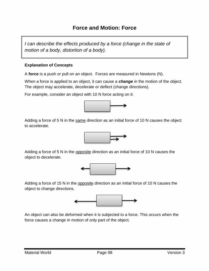
Material World Page 98 Version 3
Force and Motion: Force
I can describe the effects produced by a force (change in the state of
motion of a body, distortion of a body).
Explanation of Concepts
A force is a push or pull on an object. Forces are measured in Newtons (N).
When a force is applied to an object, it can cause a change in the motion of the object.
The object may accelerate, decelerate or deflect (change directions).
For example, consider an object with 10 N force acting on it:
Adding a force of 5 N in the same direction as an initial force of 10 N causes the object
to accelerate.
Adding a force of 5 N in the opposite direction as an initial force of 10 N causes the
object to decelerate.
Adding a force of 15 N in the opposite direction as an initial force of 10 N causes the
object to change directions.
An object can also be deformed when it is subjected to a force. This occurs when the
force causes a change in motion of only part of the object.

Material World Page 99 Version 3
Questions
The following diagram shows what happens to a golf ball when it is struck by the 1.
player’s golf club.
Explain the two effects that the force applied by the golf club has on the golf ball.
Answers
The force exerted on the golf ball causes the ball to temporarily deform when it comes into contact with the 1.
golf club. The resulting force exerted on the golf ball changes the ball’s motion. The ball accelerates, going
from a resting position to movement.

Material World Page 100 Version 3
Force and Motion: Types of Forces
I can recognize different types of forces in technical objects or
technological systems.
Explanation of Concepts
Many types of forces act on objects at any given time. Some of these forces are:
Gravitational Force:
A force of attraction between two masses (objects).
It increases when the mass of the object increases.
It decreases when the distance between the two objects increases.
Earth exerts a gravitational force on objects that cause them to accelerate
towards the Earth at 9.8 m/s2
What goes up, must come down
The Moon exerts a gravitational force on Earth that causes tides
Electromagnetic Force:
The fundamental force that is associated with electric and magnetic fields
It is responsible for atomic structure and chemical reactions,
It is responsible for the attractive and repulsive forces associated with electrical
charge and magnetism.
Friction Force:
A type of electromagnetic force (also known as a contact force) that stops two
objects from slipping past one another when they are in contact.
Nuclear Force:
It is a force of attraction between the particles that make up the nucleus of an
atom. It is the force keeps them together inside the nucleus.

Material World Page 101 Version 3
Questions
A car is accelerating on a highway. Which force is not acting on the car as it 1.
accelerates on the highway?
A) Gravity
B) Electromagnetic
C) Tension
D) Friction
Answers
D: Gravitational force is exerted by the Earth, electromagnetic forces and frictional forces act at the molecular 1.
level between the road and the tires.

Material World Page 102 Version 3
Force and Motion: Equilibrium of Two Forces
I can understand and describe conditions under which a body subjected to
two forces can be in equilibrium.
Explanation of Concepts
In most cases, many forces are acting on an object at any given time. The resultant
force is the combination of all the forces acting on an object. An object is in equilibrium
when the resultant force is zero.
If an object at rest is in equilibrium, it will remain at rest.
If an object in motion is in equilibrium, it will continue moving at a constant speed.
Forces applied to an object at rest:
Forces applied to an object in motion at constant speed:

Material World Page 103 Version 3
Questions
In which of the following situations is the box in equilibrium? 1.
Tina is travelling on her bicycle at a constant speed of 50 km/h. What is the resultant 2.
force acting on Tina and her bicycle? Explain.
2.
Answers
D: All forces that are opposite from one another have the same value and are pointing in opposite directions. 1.
The resultant force is 0 N because Tina and her bicycle are in equilibrium. She is travelling at a constant 2.
speed.

Material World Page 104 Version 3
Force and Motion:
Relationship between Constant Speed, Distance and Time
I can explain the relationship between speed, distance and time.
I can use the equation v = d/Δt to calculate constant speed, distance and
time.
Explanation of Concepts
An object’s speed is its rate of motion. The speed is the distance that is traveled per
unit of time.
If a car has a speed of 40 km/h, it means that in one hour, it travels 40 km.
Speed can be determined using the formula below:
where
v = speed (m/s or km/h)
d = distance (m or km)
∆ t = change in time ( s, h)
so so
Example:
What is the speed of a runner who runs 96 m in 12 seconds?
v = 8 m/s
The runner’s speed is 8 m/s.
t
dv
t
dv
h 1
km 1km/h 1
s 1
m 1m/s 1
t
dv
s 12
m 96v

Material World Page 105 Version 3
Questions
A car is travelling at a speed of 110 km/h to get to the winter carnival in Quebec city. 1.
The trip takes 3.0 hours. How far is Quebec city from the departure location?
A) 0.030 km
B) 37 km
C) 330 km
D) 1188 km
Four race car drivers are competing for maximum speed achieved on a straight 2.
road. The results are shown in the following table:
Race Results
Driver Distance Travelled Elapsed Time
1 27 km 5.0 minutes
2 40000 m 0.13 h
3 60 km 20 minutes
4 81 000 m 0.25 h
Which driver is the winner by having attained the highest average speed? Show your
calculations.
Answers
C 1.
d= v x ∆t
v= 110 km/ h x 3.0 h
v= 330 km
Driver 1 2.
Driver 1: Driver 2: Driver 3: Driver 4:
5/60 = 0.083 h 40,000 /1000 = 40 km 20/60 = 0.33 h 81000m /1000 = 81.25km
V = d/∆t V = d/∆t V = d/∆t V = d/∆t
V = 27km/0.083h V = 40km/0.13h V = 60 km/0.33h V = 81.25km/0.25h
V = 330 km/h V = 310 km/h V = 180 km/h V = 320 km/h

Material World Page 106 Version 3
Force and Motion: Distinction between Mass and Weight
I can explain the relationship between mass and weight.
I can use the equation Fg = mg to calculate mass and weight.
Explanation of Concepts
Mass
An object’s mass represents the amount of matter it contains. It is measured in
kilograms (kg).
Weight
An object’s weight represents the gravitational force acting on it. It is measured in
Newtons (N). The weight of an object depends on an object’s mass.
The weight of an object can change if the gravitational force changes.
The weight of an object can be found using the following mathematical formula:
Fg = m g where
Fg = gravitational force or weight (N)
m = mass (kg)
g = intensity of gravitational field (N/kg or m/s2)
(acceleration due to gravity)
Note:
The intensity of the gravitational force on Earth is always equal to 9.8 N/kg (or
m/s2).
The gravitational force between two objects depends on their masses and the
distance between them.
Since the intensity of the gravitational field depends on its mass, “g” is different
for other planets or the moon.

Material World Page 107 Version 3
Questions
Consider the following statements: 1.
1. Measures the amount of matter in an object
2. Is measured in Newtons
3. Is not a force
4. Remains constant regardless of location
5. Measures the force of gravity on an object
Which statements refer to the measurement of mass?
A) 1 and 4 only B) 2 and 5 only C) 1,2 and 4 D) 1, 3 and 4
Luca has a mass of 63.6 kg. What is Luca’s weight on the moon given that the 2.
gravitational acceleration of the moon is 1.67 N/kg?
A) 106 N
B) 106 kg
C) 63.6 kg
D) 63.6 N

Material World Page 108 Version 3
A robot was designed by NASA to explore three planets. Its function was to land on 3.
each planet and to perform tests with dynamometers (spring scales). The data
collected was used to confirm the gravitational fields of those planets.
The following information was recorded:
Planet Gravitational Force
Acting on Object (N) Mass of object (kg)
Planet 1 10.98 3.0
Planet 2 16.74 4.5
Planet 3 60.34 7.0
Unfortunately, the planets’ names were missing from the data gathered. Based on
the data above and the table below, identify each unknown planet. Show your work.
Planets’ Gravitational Fields
Planet Intensity of Gravitational Field (N/kg)
Saturn 11.27
Mercury 3.63
Venus 8.62
Neptune 11.56
Mars 3.72
Answers
D 1.
A: Fg = m g = 63.6 kg x 1.67 N/ kg 2.
3.
Planet 1 Planet 2 Planet 3
F= mg
g=F/m
g=10.89N/3.0 kg
g= 3.6 N/kg
Planet 1 is Mercury
F= mg
g=F/m
g=16.74 N/4.5 kg
g= 3.7 N/kg
Planet 2 is Mars
F= mg
g=F/m
g=60.34 N/7.0 kg
g= 8.6 N/kg
Planet 3 is Venus

TECHNOLOGICAL WORLD

Technological World Page 110 Version 3
Graphical Language
I can interpret an exploded view drawing of a technical object.
Explanation of Concepts
An exploded view is a technical diagram of an object that shows the relationship or the
order of assembly of the various components. The components of the object are shown
slightly separated.
An example of an exploded view drawing is shown below. The legend indicates the
name of each numbered component as well as the quantity (QTY) of those components
required for the assembly of the object.
Gear Pump – Exploded View Drawing
Image from:
http://commons.wikimedia.org/wiki/File:Gear_
pump_exploded.png
In the example above, the component labelled, “1” is the axle and there is one axle in
the Gear Pump. The component labelled “7” is a bolt and there are 10 bolts in the gear
pump.
Item QTY Name
1 1 Axle
2 1 Seal
3 1 Housing
4 4 Bushings
5 1 Idler gear
6 1 Housing Cover
7 10 Bolts
8 1 Case seal
9 1 Driver Gear

Technological World Page 111 Version 3
Graphical Language
I can identify and use force and motion symbols.
Explanation of Concepts
Motion and Force Symbols
Motion
Motion is characterized by the change in
the position of a body relative to another,
which is called an inertial or non-inertial
reference system.
Force
Force refers to the capacity to act or
produce an effect or any action that
changes a body’s state of rest or motion.
Rectilinear translation in one
direction
Force that tends to STRETCH the
bodies or PULL them.
Rectilinear translation in two
directions
Force that tends to SQUEEZE the
bodies or PUSH them.
Rotation in one direction
Force that tends to TWIST bodies.
Rotation in two directions
Force that tends to SPLIT bodies.
Helical

Technological World Page 112 Version 3
Graphical Language: Multiview Orthogonal Projection
I can draw a multiview orthogonal projection of a simple object.
Explanation of Concepts
A multiview orthogonal projection is a type of technical drawing that shows multiple
views of the same object (e.g. top, side and front).
The principal view or front view is the view that shows the most about the product. It is
usually the longest view and shows the major shape or profile.
Visible lines are shown as solid lines and hidden lines are shown as dotted lines on the
same view.
Example:
Multiview Orthogonal Projection of an Object
Hidden line
Visible line

Technological World Page 113 Version 3
Questions
1. An isometric projection of a three-dimensional object is shown below.
FRONT
What is the correct SIDE view of the object?
A)
B)
C)
D)

Technological World Page 114 Version 3
2. Complete the top view of the isometric projection by drawing the missing feature lines.
3. Complete all three views of the isometric projection by drawing the missing hidden feature lines.

Technological World Page 115 Version 3
Answers
A 1.
2.
3.

Technological World Page 116 Version 3
Graphical Language: Multiview Orthogonal Projection
I can interpret assembly drawings of technical objects consisting of a small
number of parts.
An assembly drawing is a graphical representation of technical objects that have more than one component.
An assembly drawing includes details such as:
a list of all the components and sub-assemblies
the general arrangement of these components and sub-assemblies
how these components and sub-assemblies fit together in the fully assembled object
the overall dimensions
how parts link together and/or what types of lubricant to use.
Assembly drawings do not contain enough information to manufacture the components but are intended to show how the manufactured components combine together to form the object.
The exploded view drawing on page 111 is an example of an assembly drawing.

Technological World Page 117 Version 3
Graphical Language: Functional Dimensioning
I can define functional dimensioning as ‘the set of specific tolerances
related to certain parts responsible for the smooth operation of an
object’.
I understand that play is ‘the space allowed between two parts to
ensure that they can move freely’.
Explanation of Concepts
Tolerance is the amount of acceptable deviation from the precise dimension of a part.
Tolerance can have an upper (maximum) and lower (minimum) limit.
e.g., 4.27 0.04 mm means the manufactured part can measure:
A maximum of 4.27 + 0.04 = 4.31 mm
A minimum of 4.27 – 0.04 = 4.23 mm
Sometimes the acceptable deviation above the dimension and the acceptable deviation
below the dimension are different.
Examples of Functional Dimensioning
Functional Dimension (mm)
Maximum dimension of manufactured part
(mm)
Minimum dimension of manufactured part
(mm)
32.5 +0.1 32.6 32.5
32.5 −0.1 32.5 32.4
32.8 32.4
32.5 0.1 32.6 32.4
If tolerance is not respected, the components may not fit together when an object is
assembled.
In order to have an object with moving parts, there needs to be room for movement.
This bit of space that allows the components to fit or move properly is known as play.
The need for play must be taken into account when designing an object.
0.3
0.1 32.5

Technological World Page 118 Version 3
The functional dimensioning includes the range of measurements that will ensure
there is enough play so that the parts can move appropriately.
Questions
A diagram of a wheel axle and car frame is shown below. 1.
Which set of dimensions will allow the axle to fit into the opening in the car frame?
Diameter of Axle (mm)
Diameter of opening in Car Frame (mm)
A) 5.27 0.03 5.26 0.01
B) 5.26 0.01 5.27 0.03
C) 5.26 0.01 5.29 0.01
D) 5.27 0.01 5.26 0.03
Opening with
0.01 mm of play
Answers
C: Axle can be 5.25 mm to 5.27 mm and fit in an opening of 5.28 mm to 5.30 mm given a play of 0.01mm 1.

Technological World Page 119 Version 3
Graphical Language: Developments
I understand how three-dimensional shapes (prism, cylinder, pyramid,
cone) can be created from sheet stock.
Explanation of Concepts
Many objects are fabricated from sheets of plastic or metal and, with some folding,
become three dimensional objects. The unfolded 3D object is called the ‘development’
or in mathematics, the ’net’.
When visualizing an object from its development/net, it is important to remember that
separated, nearby edges usually join.
Example:

Technological World Page 120 Version 3
Graphical Language: Developments
I can draw developments of simple solids.
Explanation of Concepts
Developments of Simple Solids
Solid Example of Development
Pyramid
Cylinder
Cube
Rectangular Prism

Technological World Page 121 Version 3
Questions
Which one of the following developments does not represent this figure? 1.
A)
B)
C)
D)
Why is a development helpful in the design and building of a technical object? 2.
Answers
B 1.
A development/net is useful because it shows how to manufacture a 3D object from a flat material (e.g. 2.
sheets) by folding.

Technological World Page 122 Version 3
Graphical Language: Standards and Representations
I can choose the appropriate type of diagram for a given representation.
Explanation of Concepts
Depending on the purpose of the representation, the following types of diagrams can be
used to represent a technical object.
Diagram of principle (design plan): focuses on the forces applied to the object and
the resulting motion of parts of an object
Construction diagram: focuses on specific building information for an object

Technological World Page 123 Version 3
Graphical Language: Standards and Representations
I can represent different types of motion related to the operation of an
object using the appropriate symbols (rectilinear translation, rotation,
helical).
Explanation of Concepts
Motion is characterized by the change in the position of a body relative to another,
which is called an inertial or non-inertial reference system.
Motion Symbols
Rectilinear translation in one direction
Rectilinear translation in two directions
Rotation in one direction
Rotation in two directions
Helical

Technological World Page 124 Version 3
Mechanical Engineering: Adhesion and Friction of Parts
I can describe the advantages/ disadvantages of the adhesion and friction
of parts in a technical object.
Explanation of Concepts
Adhesion occurs when two surfaces can remain in contact with each other without
slipping e.g. the tires of a car adhere to the road.
Friction is a force that acts in the opposite direction to movement. Friction resists the
slipping of one surface moving over another.
Advantage of adhesion and friction: controlling motion. e.g. When the brakes are
applied on a bicycle, the friction between the brake pads and the wheel, slows the
motion of the wheel.
Disadvantages of adhesion and friction: wearing down of parts of an object and
production of unwanted heat. e.g. Friction occurs between the moving parts of a car
engine. The friction is reduced by adding a lubricant such as oil. Nonetheless, the car
engine does heat up with use.
Factors that affect the amount of adhesion and friction between two surfaces:
The amount of surface area in contact
The nature of the material (e.g. Teflon can be used to coat a pan so food does
not stick, tires are made from rubber so they adhere to the road)
Temperature (In general, the lower the temperature, the less adhesion)
The texture of the surface (rough or smooth)
The amount of perpendicular force applied to a surface area

Technological World Page 125 Version 3
Examples of Adhesion and Friction for a Bicycle
The rough surface of the pedal allows for adhesion between the shoe of the cyclist and the pedal
1
The friction between the chain and the sprocket may cause wearing of the parts over time. This can be reduced with proper cleaning and the use of a lubricant.
2
Images from:
1. http://commons.wikimedia.org/wiki/File:13-01-06-fahrradkram-05.jpg Retrieved November 2013
2. http://commons.wikimedia.org/wiki/File:Shimano_xt_rear_derailleur.jpg Retrieved November 2013

Technological World Page 126 Version 3
Questions
A bicyclist is planning a 100 km circuit. Which one of the following measures will 1.
increase the effort it takes to complete the circuit?
1. Increase the width of the tires
2. Add weight over the rear wheel
3. Slightly deflate the tires.
A) 1 and 2 B) 1 and 3 C) 2 and 3 D) 1, 2, and 3
Explain the advantages and disadvantages of replacing narrow racing tires on a bike 2.
with wider tires.
Answers
D: Increasing the width of the tire (by deflation or other) and adding weight on the tire would increase the 1.
amount of friction thus, slowing the cyclist.
Wider tires would increase the amount of adhesion. This is an advantage since it will provide better traction 2.
(grip).
Wider tires will increase the amount of friction. This can be a disadvantage since friction will cause the cyclist
to use more energy. This can tire out the cyclist causing the cyclist to slow down.

Technological World Page 127 Version 3
Mechanical Engineering: Linking of Mechanical Parts
I can describe the characteristics of the links in a technical object (direct or
indirect, rigid or flexible, removable or permanent, partial or complete).
Explanation of Concepts
A link holds two or more parts of the same technical object together.
Every link displays four basic characteristics:
Direct
two parts held together without a
linking component
OR
Indirect
a linking component is required to
hold the two parts together
Rigid
the linking component is not
flexible
OR
Flexible
the linking component can be
deformed when used and has the
ability to return to its initial position
Removable
the linked parts can be
separated without damaging
either their surfaces or the
linking component
OR
Permanent
the linked parts cannot be
separated without damaging
either their surfaces or the linking
component
Complete
the linking component prevents
the two parts from moving
independently of one another
OR
Partial
the linking component allows the
two parts to move independently
from one another

Technological World Page 128 Version 3
Questions to Help Identify the Characteristics of Links
Characteristic Question
Direct or indirect?
Do the parts require something else to hold them together?
Yes Indirect
No Direct
Rigid or flexible?
Can the linking component be deformed when used and will it return to its initial position?
Yes Flexible
No Rigid
Removable or permanent?
Can the object be taken apart without causing damage to the object?
Yes Removable
No Permanent
Complete or partial?
Is movement possible between the two parts?
Yes Partial
No Complete
Example:
Characteristics of the link between the handle and the punch of a hole punch
The characteristics of the link between the handle and the punch are:
Direct, rigid, permanent, and fixed
Punch
Handle

Technological World Page 129 Version 3
Shelf and side panel Note: the shelves are
glued in place
Two prongs
Questions
Select the four characteristics of the link between the components identified for each 1.
technical object shown below.
a) Bookshelf
Direct or Indirect
Complete or Partial
Removable or Permanent
Rigid or Flexible
b)
Direct or Indirect
Complete or Partial
Removable or Permanent
Rigid or Flexible
c)
Clothespin Direct or Indirect
Complete or Partial
Removable or Permanent
Rigid or Flexible
Light bulb and
socket
Answers
1.
a) Indirect, complete, permanent, rigid
b) Direct, complete, removable, rigid
c) Indirect, partial, removable, flexible

Technological World Page 130 Version 3
Mechanical Engineering: Linking of Mechanical Parts
I can determine the characteristics of links that are most suitable in the
design of a technical object.
Explanation of Concepts
When objects contain two or more parts, engineers must determine how to connect
these parts. When designing an object which will require links in its construction, how
the object operates will determine the choice of link selected.
Example:
Questions
A washing machine contains many parts that may break down over time. What 1.
would be the best system to attach the back cover to the body of the washing
machine to permit access for repairs.
A) rivet
B) glue (adhesive)
C) screw
D) nail
A small screw is usually used to link the arm of a pair of glasses to the frame. 2.
Explain why this is a good choice by referring to the characteristics of the link.
The two blades of the scissors must be
linked in a way that allows the blades to
slide over each other, but not to separate.
In this case, a rivet was chosen as a linking
component. The rivet provides a link which
is moveable, indirect, rigid and non-
removable.
Answers
C 1.
The screw creates a link that is removable, indirect, so the arm can be replaced. The link is partial to permit 2.
movement.

Technological World Page 131 Version 3
Mechanical Engineering: Linking of Mechanical Parts
I can judge the choice of assembly solutions in a technical object.
Explanation of Concepts
While engineers are designing technical objects, they must judge the appropriate choice
for the materials used to initially construct the object and what to use to link the
components together.
Example: Assembly Solutions for a Skateboard
Skateboard-truck:
Image from:
http://commons.wikimedia.org/wiki/File:Skateboard-truck.jpg,
Retrieved November 2013
The baseplate of the truck is screwed
to the deck of the skateboard.
A rubber bushing provides the
cushion mechanism for turning the
skateboard.
The kingpin runs through the axle
piece, the bushing and the baseplate
in order to keep these parts together.
A loosely screwed kingpin allows for
better manoeuvring (turning).
A tightly screwed kingpin gives the
skateboard more stability.
The wheels are removable to fit the
needs of the rider and to replace
when worn.
Questions
Explain the choice to assemble an upright bookshelf with nails instead of screws. 1.
baseplate
axle
Bushing
(rubber)
kingpin
Answers
The choice to use nails to assemble an upright bookshelf could be for the following reasons: 1.
The bookshelf is meant to be permanently assembled without the need to be taken apart, nails are faster to
use.

Technological World Page 132 Version 3
Mechanical Engineering: Linking of Mechanical Parts
I can explain the purpose of limiting motion (degrees of freedom) in a
technical object.
Explanation of Concepts
The degrees of freedom of a part are the number of ways a part can move
independently.
If an object could exist totally independent from any other object it would have 6
degrees of motion freedom, translation along 3 axes, and rotation around the same
three axes.
When components are linked in a technical object, the independent motion of one part
with respect to another is limited. The extent to which the motion of the components is
limited depends on how the object needs to function.
Example:
The motion of a drawer in a filing cabinet is limited to translation along one axis. (1
degree of freedom) In order to function properly rotation or translation along other axes
is limited.
Image courtesy of the Science and Technology Implementation Committee (STIC)

Technological World Page 133 Version 3
Mechanical Engineering: Linking of Mechanical Parts
I can explain the choice of a type of link in a technical object.
When analyzing a technical object, it is important to examine why a certain type of link
has been used in its construction.
In order to do this, one must consider the characteristics of the link itself and how these
characteristics play a role in the functioning of the object.
Example: A Cider Press
Function: A cider press is used to crush apples into an unfiltered, unsweetened juice.
A drawing of the squeeze plate system is shown in the circle above. In this system, a
circular metal plate is welded to a piano screw.
The characteristics of the link between the metal plate and the piano screw are:
Direct, Rigid, Permanent, and Complete
In order for the cider press to function properly, it is important that the metal plate stays
attached to the piano screw, and that all movement all of movement of the piano screw
is transmitted to the metal. Therefore, the type of link used allows for the cider press to
function properly.

Technological World Page 134 Version 3
Mechanical Engineering: Guiding Control
I can explain the choice of a type of guiding control in a technical object.
Explanation of Concepts
Guiding is the mechanical function performed by any component that controls the
motion of one or more moving parts. A guiding component or control is a component
whose mechanical function is to guide the motion of moving parts.
There are three main types of guiding: translational, rotational and helical.
1. Translational guidance ensures the straight translational motion of a moving part.
2. Rotational guidance ensures the rotational motion of a moving part.
A track at the top and bottom of the window
frame allows the translational guiding when
the window is slid open.
The axle attached to the bicycle frame guides
the wheel in a rotational motion.
axle

Technological World Page 135 Version 3
3. Helical guidance ensures the translational motion of a moving part while it rotates
around the same axis.
Questions
View the video on this web page. bit.ly/QvCYAF
Which type of guiding control was used in the vice?
1. Rotational
2. Translational
3. Helical
A) 1 and 2 B) 1, 2, and 3 C) 2 and 3 D) 1 and 3
View the video on this web page bit.ly/1tys64c 2.
Which type of guiding control was used in the vice?
1. Rotational
2. Translational
3. Helical
A) 1 and 2 B) 1, 2, and 3 C) 2 and 3 D) 1 and 3
Threads inside the frame of the C-clamp
control the helical guiding of the threaded
shank.

Technological World Page 136 Version 3
3. State the main type of guiding control for each item below.
a) Peanut Butter Jar
b) Window
c) File Cabinet Drawer
d) Door Handle
e) C-clamp
f) Laptop
Answers
A: There is no helical guidance because the part in translation (vice jaw) does not rotate and the part that 1.
rotates (the screw) does not translate. See video:bit.ly/1hdEx01
C: The body of the vice provides helical guidance because the screw rotates and translates at the same time. 2.
The moving jaw of the vice translates. See video: bit.ly/RRZQvb (click on folder)
3.
a) helical
b) translational
c) translational
d) rotational
e) helical
f) rotational

Technological World Page 137 Version 3
Mechanical Engineering:
Motion Transmission and Motion Transformation Systems
In Secondary 4, you are required to analyze certain motion transmission and motion
transformation systems.
Here are some key points to consider:
1. Identify the driver and driven components
Kinematic chains have driver components, intermediary components, and
driven (receptor) components.
e.g. A bicycle has a front sprocket (driver) a chain (intermediary) and rear
sprocket (driven component or “receptor”)
2. Identify whether the systems transmits or transforms motion.
A transmission of motion occurs when the driven component has the same
motion as the driver component (rotation to rotation, translation to translation).
A transformation of motion occurs when the driven component has a different
motion from the driver component (rotation to translation, translation to rotation)
3. Examine the system to see if a speed change is taking place.
If necessary, refer to the section on speed changes.
4. Determine whether the system is reversible.
A system is considered to be reversible if the driver component and the driven
component can be interchanged and the system still functions. i.e. The driver can
become the driven component and the driven component can become the driver
A system is considered to be irreversible if the exchange of the driver and the
driven component results in a mechanical dysfunction.

Technological World Page 138 Version 3
Mechanical Engineering: Motion Transmission Systems
I understand the construction and characteristics of the following motion
transmission systems.
Explanation of Concepts
Friction Gears
Symbol
Description Rotational motion is transmitted from one wheel to the other
Transmission is done by friction between wheels
Rotation direction is opposite in each connecting wheel
Reversibility Yes
Advantages
Easy to assemble
Inexpensive to make
Will allow slippage, protecting it from damage
Gears can be positioned perpendicular or at any angle to each other
Disadvantages Wheels must always be together even as they wear away
Wheels can slip, causing interruption in transmission of motion
Must be kept clean(free of lubricants)

Technological World Page 139 Version 3
Gear Assembly
Symbol
Description
Rotational motion is transmitted from one gear to the other
Rotation direction is opposite in each connecting gear
System can have more than two gear wheels
Used in machinery where mechanical advantage is needed
The torque(force) of a small motor can be increased considerably through a gear train
Requires fine machining of parts so that the teeth fit together precisely
Reversibility Yes
Advantages Will not allow slippage
Can be connected at various angles
Allows for large forces to transmitted
Disadvantages
Needs lubrication
Subject to severe damage if there is a failure in any one part of the system
Requires elaborate machining
Pulley and Belt
Symbol
Description
Rotational motion is transmitted from one pulley to the other by a belt
Rotation direction is opposite in each wheel
System can have more than two wheels
Reversibility Yes
Advantages Easy to assemble
Will allow slippage, protecting it from damage
Allow for transmission of motion over long distances e.g. ski lift
Disadvantages Slippage will occur with wear and improper tension on the belt
Belt and Pulleys must be kept clean(free of lubricants)
Belt can be subject to premature wear

Technological World Page 140 Version 3
Sprocket Wheels and Chain
Symbol
Description
Rotational motion is transmitted from one sprocket to the other by a chain
Rotation direction is opposite in each connecting sprocket
System can have more than two sprockets
Used in machinery where mechanical advantage is needed
The teeth of the sprockets must be identical so that one chain securely fits all the sprockets
In a given system, the smaller the sprocket the faster it will rotate
Reversibility Yes
Advantages Will not allow slippage
Allows for large forces to be transmitted
Disadvantages Needs lubrication
Wheel and Worm Gear
Symbol
Description
Rotational motion is transmitted from the worm gear to one or more wheel gears(sprocket)
Used in machinery where fine adjustment is needed
One turn of the worm gear advances the wheel by one tooth. the above example requires eight turns of the worm gear for one complete revolution of the wheel
Requires fine machining of parts so that the wheel gear teeth fit precisely in the worm gear
Reversibility No. If a force is applied to the wheel gear(sprocket) the worm gear will not turn
Advantages Will not allow slippage
Allows for fine adjustment eg tuning pegs on a guitar
Disadvantages Needs lubrication
Symbols for mechanisms courtesy of Le Centre de Développement Pédagogique

Technological World Page 141 Version 3
Mechanical Engineering: Motion Transmission Systems
I am familiar with the symbols for the motion transmission systems.
Explanation of Concepts
Symbols for Motion Transmission Systems
Motion Transmission System Symbol
Friction Gears
Pulley and Belt
Gear Assembly
Sprocket Wheels and Chain
Wheel and Worm Gear
Symbols for mechanisms courtesy of Le Centre de Développement Pédagogique

Technological World Page 142 Version 3
Mechanical Engineering: Motion Transmission Systems
I can explain the choice of a motion transmission system in a technical
object.
Explanation of Concepts
During the design of a technical object, one must consider which transmission systems
are necessary and more advantageous than others. Being able to identify and explain
these advantages involves the understanding of each of these systems.
For an explanation of these systems refer back to friction gears, pulley and belt, gear
assembly, sprocket wheel and chain, and worm and worm gear systems in the previous
sections.
Example: Choice of Motion Transmission System for a Bicycle
A person riding a bicycle is regularly exerting a force on the pedals which drive the
sprocket wheel and chain.. Engineers have chosen a sprocket wheel and chain system
because of this force. The teeth of the gears fit perfectly into the chain, allowing the
chain to stay on the sprockets as the force is exerted through the pedals. If a pulley and
belt system was used, slipping would occur and the belt may not be able to withstand
the force exerted by the bicycle rider.

Technological World Page 143 Version 3
Questions
Which of the following diagrams of a motion transmission system correctly illustrates 1.
the motion of the components?
A) I and II only
B) II and III only
C) III and IV only
D) II, III and IV
Which of the following diagrams of a motion transmission system correctly illustrates 2.
the motion of the components?
A) I and II only
B) II and III only
C) II and IV only
D) I and III only
Explain why a sprocket wheel and chain system is used in a bicycle rather than a 3.
belt and pulley system

Technological World Page 144 Version 3
Answers
B 1.
C 2.
The sprocket wheel and chain system does not permit slippage, therefore the forces applied to the pedals are 3.
transmitted to the back wheel

Technological World Page 145 Version 3
Mechanical Engineering: Speed Changes
I can explain speed changes in a technical object.
Explanation of Concepts
Speed Change occurs in a motion transmission system when the driven component
rotates at a different speed than the driver.
Driver (Driving) Component: The component that receives the force needed for the
system to start working and in most cases continue to work.
Driven Component: This component receives the motion from the driver component
and transfers it to another part.
Intermediate Component: It is found between the driver and driven component. *Note
that not all systems have an intermediate component.
The speed change in motion transmission systems depends on the relative diameters of
the driver and driven components.
a) Speed Increase: Diameter of driver > diameter of driven
When the diameter of the driver component is greater than the diameter of the
driven component, there is a speed increase in the system.
e.g.
Intermediate
Driven Driver
Driver Driven Driven Driver

Technological World Page 146 Version 3
b) Speed Decrease: Diameter of driver < diameter of driven
When the diameter of the driver component is less than the diameter of the driven
component, there is a speed decrease in the system.
e.g.
c) No Speed Change: Diameter of driver = diameter of driven
When the diameter of the driver component is equal to the diameter of the driven
component, there is no speed change in the system.
e.g.
Speed Ratio
The speed ratio can be used to describe the speed change for a system.
component driven of teeth) of number (or diameter
component driver of teeth) of number (or diameterratio Speed
If the speed ratio = 1, then there is no change in speed.
If the speed ratio >1, then there is an increase in speed
If the speed ratio is <1, then there is a decrease in speed.
Driver Driven Driven Driver
Driver Driven Driven Driver

Technological World Page 147 Version 3
Questions
1. For which of the systems below will Gear 2 turn more quickly than the Gear 1?
A)
B)
C)
D)
2. Which of the systems below could produce a change in speed similar to the one in a
wheel and worm gear system?
A) Two pulleys of equal size connected by a belt
B) A large driver gear turns a smaller driven (receptor) gear
C) A small driver gear turns a middle size intermediary gear which turns a large driven (receptor) gear
D) A rack and pinion system where the pinion is the driver and the rack is the driven (receptor).

Technological World Page 148 Version 3
3. A wheel and worm gear system is shown below.
Image from: http://www.machinerylubrication.com/Read/1080/worm-gears
Retrieved: December 2013.
Given a constant speed of the driver (worm), what changes can be made to the
components of the system to increase the speed of the driven gear?
4. A gear system is shown below.
Gear 1 is the driver gear and has a diameter of 8 cm. Gear 2 has a diameter of 10.5
cm.
Which gear turns faster and what is the speed ratio for the system?
Answers
A 1.
C 2.
The best way to increase the speed in a worm and wheel transmission system is to have a gear that is 3.
smaller in diameter and/or a gear that has fewer teeth. A smaller diameter naturally takes less time to make
one full rotation and few teeth means less time having each tooth mesh with this respective part on the worm
component.
Gear 1 turns faster and the speed change ratio is 0.76. 4.

Technological World Page 149 Version 3
Mechanical Engineering: Motion Transformation Systems
I understand the construction and characteristics of the following motion
transformation systems.
Screw Gear System
Symbol
Type 1
Nut is free component Screw is fixed component
Type 2
Screw is free component Nut is fixed component
Description Rotational motion is applied to the free component to obtain
translational motion in the other component
Transforms quick rotation to slower translation
Reversibility No, because you cannot transform translational to rotational motion in this system.
Advantages Allows for precise adjustment in its use. Used in many types of
tools and machinery
Disadvantages Parts need to be lubricated
Cam and Follower
Symbol
Description
Rotational motion can be applied to cam to create translational motion on the follower. The follower must have guidance of some sort to operate properly.
Size and shape of cam and placement of axle will determine the length and action of the stroke
Reversibility No, because applying a force to the follower (moving it up and down) will not cause the cam to rotate.
Advantages Allows for very precise and custom translational motion. Timing
and distance of the follower can be determined by shape, size of cam and placement of axle on cam.
Disadvantages Parts need to be lubricated
A return mechanism (e.g. spring, gravity) must be built into design

Technological World Page 150 Version 3
Connecting Rod and Crank
Symbol
Description
Rotational motion can be applied to the crank to create translational motion in the slide. Connecting rod connects slide to crank. In order to achieve the change the slide must be guided.
Translational motion can be applied to slide to produce rotational motion in crank
Provides a mechanical advantage
Reversibility Yes, because rotational motion can be applied to the crank to produce translational motion in the slide and translational motion can be applied to the slide to produce rotational motion in the pinion.
Advantages
Allows force to be applied without slippage
Change motion from translational to rotational or vice versa
Allows force to be applied at a distance through the connecting rod
Disadvantages
Parts need to be lubricated
Very precise fit needed between slider and guidance
Reversibility is only possible in a mechanism built to precise specifications
Lever and Slide
Symbol
Description
Rotational motion can be applied to the lever to create translational motion in the slide and vice-versa. The slide must have guidance of some sort to operate properly.
The length of the lever will determine the distance that the slide will move.
Designed for short oscillatory movement
Reversibility Yes
Advantages Simple mechanism
Disadvantages Parts need to be lubricated
guide
slide
lever
crank
slide
connecting rod

Technological World Page 151 Version 3
Rotating Slider Crank Mechanism
Symbol
Description
Rotational motion is transformed to translational motion in the slide
Translational motion of the slide is transformed into partial rotational motion in the crank
Provides a mechanical advantage which is determined by the size of the wheel
Produces oscillating motion
Reversibility Yes, because rotational motion of the crank produces translational motion in the slide and translational motion of the slide produces partial rotational motion in the crank.
Advantages Change motion from translational to rotational or vice versa
Disadvantages Parts need to be lubricated
Reversibility is only partial
Rack and Pinion
Symbol
Description
Rotational motion of pinion is transformed into translational motion of rack.
Translational motion can be applied to rack to produce rotational motion in the pinion
The rack is really a toothed gear wheel that has been straightened.
Reversibility Yes because rotational motion can be applied to the pinion to produce translational motion in the rack and vice versa.
Advantages Allows force to be applied without slippage
Disadvantages Parts need to be lubricated,
Very precise fit needed between teeth of rack and pinion
crank
slide
rack
pinion

Technological World Page 152 Version 3
Mechanical Engineering: Motion Transformation Systems
I am familiar with the symbols for the motion transformation systems.
Explanation of Concepts
Symbols for Motion Transformation Systems
Motion Transformation System Symbol
Screw Gear System
Cam and Follower
Connecting Rod and Crank
Lever and Slide
Rotating Slider Crank Mechanism
Rack and Pinion

Technological World Page 153 Version 3
Mechanical Engineering: Motion Transformation Systems
I can explain the choice of a motion transformation system in a technical
object.
Explanation of Concepts
During the design of a technical object, one must consider which transformation
systems are necessary and more advantageous than others. Being able to identify and
explain these advantages involves the understanding of each of these systems.
For an explanation of these systems refer back to screw gear system, cam and follower,
connecting rod and crank, lever and slide, rotating slider crank mechanism and rack and
pinion on the previous pages.
Questions
1. A cam and follower system transforms the rotational motion of a cam into the
reciprocating translational motion of a follower. Which cam below would not allow for
both clockwise and counter-clockwise motion?
A)
B)
C)
D)
2. A student wishes to build a pull toy of a clown sitting in a cart in which a mechanism
will cause the hat of the clown to move up and down as the cart is pulled.
Which one of the systems below would not be suitable for a mechanism in this toy?
A) Crank and slide
B) Cam and follower
C) Rack and pinion
D) Crank, connecting rod, and slide

Technological World Page 154 Version 3
3. Examine the cam and follower system illustrated below.
Describe two ways the rise of the follower could be increased.
Guides
Roller follower
Eccentric cam
Answers
D 1.
C 2.
Move the center of rotation closer to the outside of the cam. Increase the size of the cam. 3.

Technological World Page 155 Version 3
Mechanical Engineering: Motion Transformation Systems
I can distinguish between cams and eccentric cams.
The most common type of cam is a rotating component with a curved outline or curved
groove that is used to transform rotational motion into the translation motion of the
follower or vice versa.
There is a great variety of cam shape. The motion of the follower depends on the
shape of the cam.
An eccentric cam is a disc with the centre of rotation placed off-centre. As the
eccentric cam rotates, the follower rises and falls.
Eccentric cam

Technological World Page 156 Version 3
Electrical Engineering: Power Supply
I understand that a power supply has ‘the ability to generate electrical
current’.
Explanation of Concepts
A power supply has the ability to generate electrical current. A battery is an example
of a power supply.
Questions
A circuit has many components. Which of the following components generates 1.
electrical current?
A) Power supply
B) Ammeter
C) Voltmeter
D) Switch
There are two types of electric drills. One has a battery while the other has to be 2.
plugged into an electrical outlet. Explain how a battery and an electrical outlet can be
classified as power supplies in a circuit.
Answers
A 1.
The battery and electrical outlet both provide current and allow the electrons to flow through a circuit. 2.

Technological World Page 157 Version 3
Electrical Engineering: Power Supply
I can determine the source of current in technical objects with an electrical
circuit.
Explanation of Concepts
Examples of the different power supplies (sources of current) in technical objects
include:
Chemical battery: Chemical reactions inside the battery transform chemical energy into
electrical energy.
Piezoelectric: Mechanical energy from vibrating crystals is transformed into electrical
energy. Piezoelectric crystals are found in clocks, timers, lighters, ultra sound devices
and speakers.
Solar cell (photovoltaic): Converts light energy to electrical energy.
Alternator: The mechanical energy of a rotating electromagnet is transformed into
electrical energy.
Thermocouple: Thermal energy is transformed into electrical energy. A thermocouple
is a sensor e.g. digital food thermometers, fridge thermometer, gas stoves and heaters.

Technological World Page 158 Version 3
Questions
A battery is a power source used in everyday objects. Which of the following objects 1.
does not use a chemical battery as a power supply?
A) Flashlight
B) Portable speakers
C) Toaster
D) Laptop
A piezoelectric quartz watch uses the vibration of crystals to keep track of time. 2.
Which type of energy transformation occurs in this system?
A) Chemical energy into electrical energy
B) Solar energy into electrical energy
C) Magnetic energy into electrical energy
D) Mechanical energy into electrical energy
Paul’s calculator screen is dull when he sits in his living room where there is little 3.
light. When he walks into a well-lit room, the screen becomes brighter. What is the
source of current in his calculator?
Answers
C 1.
D 2.
Solar cell 3.

Technological World Page 159 Version 3
Electrical Engineering: Conduction, Insulation and Protection
I can analyze the factors that affect electrical conductivity (section, length,
nature, temperature of conductor).
Explanation of Concepts
The conductivity of a substance (how well it conducts) depends on the type of
material, length, diameter and the temperature of the conductor.
The conductivity of a wire can be increased by:
Increasing the diameter of the wire
Decreasing the temperature of the wire
Decreasing the length of the wire
Changing the type of material (copper is one of the best and most affordable
materials)

Technological World Page 160 Version 3
Questions
The conductivity of a wire in an electrical toy needs to be decreased. How should the 2.
electrical engineers change the wire?
1. Increase the length
2. Increase the diameter
3. Decrease the length
4. Decrease the diameter
A) 1 and 2 B) 1 and 4 C) 2 and 3 D) 2 and 4
The properties of four copper wires are described in the table below. 3.
Properties of Copper Wires
Wire Length Diameter Temperature
A 10 m 2 mm 25 °C
B 10 m 3 mm 20 °C
C 20 m 2 mm 20 °C
D 20 m 3 mm 25 °C
Which of the copper wires has the best conductivity? Explain your answer.
Answers
B 1.
Wire B would have the highest conductivity. It has the shortest length, widest diameter and the lowest 2.
temperature, all of which are properties that increase conductivity.

Technological World Page 161 Version 3
Electrical Engineering: Conduction, Insulation and Protection
I can use the colour code to determine the electrical resistance of a
resistor.
Explanation of Concepts
A resistor is a device that slows down the flow of an electric current in a circuit. The
resistance of a resistor is measured in ohms (Ω).
The electrical resistance of a resistor is marked using a color code.
The colored bands on a resistor indicate the resistance of a resistor:
The first band is associated with the first digit.
The second band is associated with the second digit.
The third band is associated with the multiplier (x 10x)
The fourth band is associated with the tolerance (this is a percentage that is both
added and subtracted to the entire value, therefore giving you a range of
resistance).
Resistor Color Chart
Colour Black Brown Red Orange Yellow Green Blue Purple Grey White
Digit 0 1 2 3 4 5 6 7 8 9
Multiplier 100 101 102 103 104 105 106 107 108 109

Technological World Page 162 Version 3
Example:
The resistance of the resistor shown below is 32 x 105 ± 10% Ω .
The first band is orange, so the first digit is 3
The second band is red, so the second digit is 2
The third band is green, so the multiplier is 105
The last band is silver, so the range is ± 10%
Questions
1. Determine the resistance of the resistor below. Use the resistor color chart on the
previous page.
Answers
65 x 102 ± 5% Ω 1.

Technological World Page 163 Version 3
Electrical Engineering: Control
I can identify both unipolar and bipolar switches.
I can distinguish between unidirectional and bidirectional switches.
Explanation of Concepts
The function of a switch is to turn an electrical circuit on or off. Different types of
switches exist.
Types of Switches
Switch Symbol
Unipolar/unidirectional switch (single pole/single throw)
Unipolar/bidirectional switch (single pole/double throw)
A unipolar (single-pole) switch has one conductive bar and opens and closes one
contact at a time.
A unidirectional (single-throw) switch is used in circuits where the current can follow
only one path.
A bidirectional (double-throw) switch is used in circuits where the current can follow
two paths.

Technological World Page 164 Version 3
Electrical Engineering: Transformation of Energy
I can identify and explain the transformation of energy (electricity, light,
heat, vibration, magnetism) in different components of a circuit.
Explanation of Concepts
Electrical energy can be transformed into light energy, sound energy, mechanical
energy or thermal energy.
Examples of Energy Transformations in Different Circuit Components
Component Symbol Transformation
Light Bulb
Electrical Energy Light and heat
Battery
In Use:
Chemical energy Electrical energy and heat
While being charged:
Electrical energy to chemical energy and heat
Motor
Electrical energy Mechanical Energy and heat and sound
Speaker
Electrical Energy Sound and mechanical energy and heat

Technological World Page 165 Version 3
Questions
Which of the following components of a circuit transforms energy? 1.
1. light
2. switch
3. battery
4. wires
A) 2 and 4 B) 1 and 3 C) 1, 2, and 3 D) 1, 3, and 4
Answers
B 1.

Technological World Page 166 Version 3
Electrical Engineering: Transformation of Energy
I can describe the energy transformations (electricity, light, heat, vibration,
magnetism) that take place in electrical or electronic appliances.
Explanation of Concepts
Electronics and electrical appliances transform electrical energy into other forms of
energy depending on the device used in the system.
Electrical Energy can be transformed into:
Light (luminous) Energy
Sound Energy
Mechanical (movement) Energy
Thermal (heat) Energy.
Questions
A fan is designed to transform electrical energy to: 1.
A) Sound energy
B) Mechanical energy
C) Thermal energy
D) Light energy
A doorbell for the hearing impaired produces a sound and turns on a light. Explain 2.
the type of energy transformations that occur in this system.

Technological World Page 167 Version 3
Identify the transformations that occur in each of the appliances listed below as 3.
electrical energy is transformed into other forms of energy.
Appliance Useful energy (purpose of appliance) Other form(s) of energy
T.V. Light, sound Thermal
Toaster
Flashlight
Blender
Hairdryer
Radio
A diagram of a doorbell is shown below. 4.
Using the diagram above, explain the energy transformations that occur in between
the doorbell being pushed and the doorbell sounding.

Technological World Page 168 Version 3
Answers
B 1.
A doorbell transfers electrical energy into sound energy. The light of the doorbell will transfer electrical energy 2.
to light energy.
3.
Appliance Useful energy (purpose of appliance) Other form(s) of energy
T.V. Light, sound Thermal
Toaster Thermal, Mechanical Light
Flashlight Light Thermal
Blender Mechanical Sound, Thermal
Hairdryer Thermal, Mechanical Sound
Radio Sound, Light Thermal
When the doorbell is pushed, the circuit is closed. The electrical energy of the circuit is transformed into 4.
magnetic energy in the solenoid. The magnetic energy is transformed into kinetic energy as the bar in the
solenoid is attracted to the bell. The kinetic energy is then transformed into sound energy when the bar hits
the bell.

Technological World Page 169 Version 3
Electrical Engineering: Other Functions
I can describe the function of a diode.
Explanation of Concepts
A diode is an electronic component that only allows current to travel in one direction
within a circuit.
The symbol for a diode and a drawing of a diode is shown below.
Light emitting diodes (LEDs) give off light when a current flows through them.

Technological World Page 170 Version 3
Questions
The circuit is designed so that electrons can only flow in one direction to prevent 1.
damage to the circuit.
Which electronic component makes this possible?
A) A transistor
B) A switch
C) A fuse
D) A diode
Two circuits containing a diode are shown below. 2.
Circuit A Circuit B
In which circuit(s) will the light bulb light up? Explain your answer.
Answers
D 1.
The light bulb will light up in Circuit A only. Current only flows in one direction through a diode. The current 2.
flows in the correct direct through the diode in circuit A, but in circuit B, the current flows in the opposite
direction than what the diode allows.

Technological World Page 171 Version 3
Electrical Engineering: Other Functions
I can describe the function of a condenser.
Explanation of Concepts
A condenser or capacitor stores electrical energy and releases it either all at once or
in small parts for use.
A capacitor allows for the accumulation of electrical charges and can be easily
recharged. For a capacitor to be able to charge, the source must be at a higher voltage
than the capacitor's terminals.
Symbol:
Functions
To store charge for high-speed use:
An electronic flash on a camera uses a capacitor. A capacitor can discharge more
rapidly than a battery. Therefore, a battery is used to charge up the flash’s capacitor,
and then the capacitor can release the charge into the flash tube almost instantly when
needed.
To “smooth out” electrical current:
Sometimes the supplied current may not be constant. The capacitor can store the
supplied charges and slowly release the charge at a constant rate, smoothing out dips
or peaks in the current.

Technological World Page 172 Version 3
Electrical Engineering: Other Functions
I can describe the function of a solid-state relay.
Explanation of Concepts
A relay is type of control that is activated by a very low voltage. A low voltage circuit
with a relay can activate other devices in a second, higher voltage circuit.
Relays turn on or off the power being supplied to other devices in a similar fashion as a
physical switch. However, instead of being switched manually by the operator, relays
are switched electronically. With relays, high-current devices such as lights or
appliances can be controlled with low-current signals.
Relays are either electromechanical relays or solid-state relays. In electromechanical
relays contacts are opened or closed by a magnetic force. With solid-state relays, there
are no contacts and switching is electronic.
An Electromechanical Relay
When a current flows through the low voltage circuit, the magnetic field in the
electromagnet causes the reed switch to close in the higher voltage circuit. In this way,
the current in the higher voltage circuit flows.

Technological World Page 173 Version 3
Advantages of using a relay:
The low voltage circuit can be made up of small conductors, allowing for relatively small
switches to be used to control a much bigger circuit.
The risk of electrocution is lessened when a relay is used.
Examples:
A thermostat sends a small current to the relay in the motor of a furnace. The relay
then activates a circuit that controls a large amount of voltage, the motor for the furnace.
Security alarms in homes use electromechanical relays. The primary, lower voltage
circuit is closed when all doors and windows are closed. The electromagnet in the
primary circuit is activated, and its magnetic field maintains the switch in the secondary,
higher voltage alarm circuit, to stay in the “open” or “off” position. If a door is opened,
the primary circuit is broken, and the magnetic field is no longer present. The switch in
the secondary circuit then falls into the “closed” or “on” position and the alarm sounds.

Technological World Page 174 Version 3
Materials: Constraints
I can define a constraint as ‘an external force (shearing, compression,
deflection, torsion and tension) that is exerted on materials and that
has a tendency to deform them’.
Explanation of Concepts
The parts of a technological object may be subjected to one or more external
constraints or forces.
These forces can deform the parts.
Types of Constraints and Their Symbols
Constraint Description Symbol Examples
Compression
Forces that tend
to crush it.
Crushing a can.
Squeezing a wet sponge.
Tension
Forces that tend
to stretch it.
Copper being stretched
into wire.
Tug of war.
Torsion
Forces that tend
to twist it.
Hands wringing a towel.
Earthquake twisting a
bridge.
Deflection
Forces that tend
to bend it.
Fish bending a fishing rod.
Clothes pushing down on
a clothesline.
Shearing
Forces that tend
to cut. Scissors cutting paper.

Technological World Page 175 Version 3
Questions
The following image is an example of what type of constraint? 1.
A) Compression
B) Torsion
C) Deflection
D) Tension
The following image is an example of what type of constraint? 2.
A) Compression
B) Torsion
C) Deflection
D) Tension
A new bridge is being built for cars to cross the St. Lawrence River. What types of 3.
constraints must an engineer consider when he is designing the bridge?
Answers
C 1.
B 2.
The top of the beams will be subjected to compression force by the traffic on the bridge, while at the same 3.
time the bottom of the beam is subjected to tension. Where the beams are supported on the pillars shearing
forces must be taken into account. The pillars are subjected to compression forces from the weight of the
bridge.

Technological World Page 176 Version 3
Materials: Constraints
I can explain the choice of a material based on its properties.
Explanation of Concepts
Materials used in construction of technical objects have different properties.
When choosing a material for an object, the forces or constraints the object will be
subjected to will help determine which material is most suitable.
Examples:
Steel is selected for the construction of manhole covers because it is malleable,
hard and resistant.
Copper is selected for the construction of electrical cables. In addition to being
conductive, it is highly ductile, allowing it to be drawn into long wires and cables.
Glass is selected for the cover of fire alarms. The fragility of the glass allows it to
be broken easily so the fire alarm can be accessed.
Questions
John wants to build a go-cart in order to enter a race taking place this summer. What 1.
material(s) should he use for each of the parts listed below? Explain your answer.
a) Tire
b) Body Frame
c) Seats

Technological World Page 177 Version 3
Hockey sticks are made from a material that can resist indentation and shock when 2.
coming into contact with a puck or the ice. The material also has to be lightweight to
be easily handled by the player. Here is a list of possible materials to choose from:
Materials Properties
Steel
Hardness
Resilience
Ductility
High density
High thermal conductivity
Carbon fibre
Low density
Hardness
Resilience
Electrical conductivity
Resistant to corrosion
Rigidity
Polymethyl (acrylic)
Hardness
Rigidity
Comes in a variety of colours
Malleability
Brittleness
Polyamide (nylon)
Resilient
Medium hardness
Flexible
High moisture absorbance
Which of the materials above would be the best material to use for a hockey stick?
Explain your choice by using the properties of the materials.

Technological World Page 178 Version 3
Answers
1.
a) The tires should be made of rubber. The material needs to be strong enough to resist friction due to
driving at fast speeds. It also needs to be able to grip the asphalt and provide as smooth a ride as
possible. It must also be easily changeable in case of damage or accident.
b) The body frame should be made of aluminum due to its malleability and lightweight properties. This will
allow the go-cart to go faster because it is lightweight and the malleability allows the builder to bend the
structure according to their vision for the final product.
c) The seats should be made of various materials. Metal can be used to make the shape of the seat.
Foam, covered by leather, vinyl, or cloth, can be used for the cushion
The best material would be carbon fibre because: 2.
Low density: light weight
Hardness and resilience: resistance to denting and shocks
Resistance to corrosion: subjected to ice and water
Rigidity: resistance to application of constraints.

Technological World Page 179 Version 3
Materials: Heat Treatments
I understand that heat treatments can be used to change the properties of
materials (quenching increases hardness but fragility as well).
Explanation of Concepts
The properties of some materials can be changed using various heat treatments. For
example, heating wood to a high temperature can protect it from degradation by
enhancing its properties.
Quench hardening and tempering are techniques used to enhance the hardness of
steel, making it less brittle. First, the metal is heated to reorganize the atoms inside it.
Then it is cooled by a liquid to set the new atom arrangement. This results in hard, but
brittle steel. Lastly, the steel is made less brittle by a second heating period.
Annealing is another kind of heat treatment used to restore the properties of steel once
they have been modified by welding, for example.
Questions
Which of the following is not an example of a type of heat treatment? 1.
A) The side windows of cars are made of glass that is heated to increase its
hardness and make it more brittle.
B) Aluminum alloys used to make the body of a car are treated with heat to increase
hardness and strength.
C) Brass instruments are heat treated to increase strength and prevent cracking.
D) Two metal rods are joined together by heating metal (welding).
Knives are made by heating steel blades at very high temperatures and then dipping 2.
them in liquid nitrogen (very cold). Name the heat treatment(s) described and
explain its advantages as far as the properties of the steel blades are concerned.
Answers
D 1.
Heating rearranges the atoms inside the steel blade. Cooling in liquid nitrogen is called quench hardening. 2.
This process makes the steel blades much harder and resistant to indentation and keeps the blade sharper
longer.

Technological World Page 180 Version 3
Materials: Types and Properties
I can relate the use of thermoplastics to their properties.
I can relate the use of thermosetting plastics to their properties.
Explanation of Concepts
Plastics are materials made of polymers that combine in different ways to obtain various
properties.
Plastics fit into two categories: thermoplastics and thermosetting plastics.
Thermoplastics can be heated to soften and shaped over and over again. They can
harden when cooled and keep their properties. Some properties of thermoplastics are:
Chemical neutrality (unreactive)
Elasticity
Lightness
Resilience
Corrosion resistance
Thermosetting plastics can only be heated and shaped once. Once shaped, they
remain hard, even when re heated. Some properties of thermosetting plastics are:
Hardness
Resilience
Heat resistance
Stiffness
Since thermosetting plastics retain their shape and strength when heated, they are used
in situations where resistance to heat is important. Cooking pot handles, kitchen
counters and electrical fittings are made from thermoplastics.

Technological World Page 181 Version 3
Materials: Types and Properties
I can relate the use of ceramics to their properties.
Explanation of Concepts
Ceramics are the result of heating inorganic matter. Some properties of ceramics are:
Hardness
Low electrical conductivity
Wear resistance
Heat resistance
Corrosion resistance
Questions
1. Why would a homeowner choose a ceramic floor in the kitchen and bathroom rather
than a wooden floor?
Answers
Ceramic floors in the kitchen and bathrooms are ideal because these rooms deal with water. Wood would rot 1.
if it was exposed to water over a longer period of time whereas ceramic does no absorb water, can be easily
cleaned if exposed to water and can last a long time.

Technological World Page 182 Version 3
Materials: Modification of Properties
I can describe different treatments to prevent degradation of materials.
Explanation of Concepts
Over time materials can degrade. As a result, several techniques and treatments have
been developed to help prevent degradation and allow the material last longer.
Some techniques used to prevent degradation are described below.
Wood and Modified Wood:
Varnish
Paint
Treatment with a special protective coating like an alkaline solution that contains copper (Turns the wood bluish).
Subjecting it to high temperature
Ceramics:
Heating
Coating them in enamel a protective coating
Avoiding exposing them to acids, bases and thermal shock
Note: Ceramics are generally very durable. They are even found in archeological
digs.
Metals and Alloys:
Coating the metal with treatments.
Metallic Coatings: zinc, chrome, gold, silver, nickel, aluminum, lead
Other Coatings: paint, enamel, grease, resin
Exposing to high heat to make the material harder like steel
Plastics:
Protecting the plastic with waterproof coatings
Adding antioxidants like carbon to prevent oxidation
Adding pigments that absorb UV rays

Technological World Page 183 Version 3
Composites:
Two main problems with composites that lead to degradation are deformation and loss of adherence between the materials.
To prevent degradation again depends on the materials used in making the composite and applying the protection to the material.
Questions
You are thinking of building of a deck in your backyard. You look at a neighbor’s 1.
deck and see that it is discolored and rotten in certain places.
a) How can you explain the state of your neighbor’s deck?
b) How could you prevent your deck from looking like your neighbor’s?
Answers
1.
a) The neighbor’s deck is discolored and rotten due to the fact that the wood was not treated against
possible degradation. As a result, rotting occurred.
b) It is best to use wood that has been pressure treated with a preservative. The wood also needs to be
sealed with varnish or a weather treatment to prolong the life span of the wood especially if it will be
exposed to harsh climate conditions and many forms of precipitation

Technological World Page 184 Version 3
Manufacturing:
Characteristics of Drilling, Tapping, Threading and Bending
I can describe the characteristics of the tools needed to shape a material.
Explanation of Concepts
Different tools are used to shape materials.
Drilling: The appropriate drill bit for a task depends on the type of material being drilled
into (i.e. bored into), the diameter of the hole needed, and the speed at which the bit will
rotate.
Example:
The tip of a drill bit for metal is conical and the tip of a drill bit for wood is double fluted.
Metal Drill Bit Wood Drill Bit
Tapping: Tapping is the process to make screw threads inside the hole of a bored
material. This makes it easier for threaded objects to fit into the hole. The tool used to
make the inner threads is called a tap. The tap already has threads and requires a ‘tap
wrench’ to tap a material.
Threading: Threading is the process by which screw threads are etched or formed on
the outside of a rod. The tool used to make the outer thread is called a diestock. A
diestock already has threads and is rotated around the rod to make the threads on the
rod (wood, metal or plastic). A diestock must be used slowly in order to avoid any
errors.
Bending: is the process by which a material is pressed into shape. The tool used to
form a piece of sheet metal or thermoplastic is a machine press.

Technological World Page 185 Version 3
Questions
Which manufacturing technique is used to prepare the inside of a material so that a 1.
screw can go in it securely?
A) Drilling
B) Tapping
C) Threading
D) Bending
What factor must be considered when determining the speed of rotation of a 2.
diestock?
Answers
B 1.
A diestock should rotate at a constant speed and not too quickly. The slow speed will ensure that the threads 2.
are made evenly with minimal distortion.