applied ocean research - sia.cnir.sia.cn/bitstream/173321/18674/1/design of a novel...
TRANSCRIPT

D
Ya
b
c
a
ARRAA
KSIFTN
1
sbociaimd(a
om(DpdmDt
h0
Applied Ocean Research 59 (2016) 24–37
Contents lists available at ScienceDirect
Applied Ocean Research
journal homepage: www.elsevier.com/locate/apor
esign of a novel installation device for a subsea production system
uguang Cao a,∗, Xueyang Hu a, Shihua Zhang b, Songsen Xu b, Jungin Lee a, Jiancheng Yu c
Province Key Laboratory of Safety of Oil & Gas Storage and Transportation, China University of Petroleum, Qingdao, ChinaDriling Technology Institute of Shengli Petroleum Bureau, Dongying, ChinaState Key Laboratory of Robotics, Shenyang Institute of Automation, Chinese Academy of Sciences, Shenyang, China
r t i c l e i n f o
rticle history:eceived 24 June 2015eceived in revised form 5 May 2016ccepted 11 May 2016vailable online 27 May 2016
a b s t r a c t
Subsea production systems (SPSs) have dominated the exploration of deep-sea oil and gas fields becauseof their economic superiority. SPS is a high-investment and high-risk technology. A floating installationdevice (FID) and an installation method for the SPS using this device were designed in this study. Thedevice is made of buoyant materials, allowing both the SPS and the FID to be kept in a suspended state.Thus, the restriction caused by the great weight of the SPS can be avoided. The dynamic response of the
eywords:ubsea production systemnstallation methodloating installation deviceheoretical computation
chain system and FID was analysed according to environmental loads and material characteristics. Thefeasibility of the design was validated through numerical simulation and theoretical computation.
© 2016 Elsevier Ltd. All rights reserved.
umerical simulation
. Introduction
The subsea production system (SPS) consists of several typicalubsystems, including a wellhead, a Christmas tree, a manifold, aridge pipe and so on. This system has dominated the explorationf deep-sea oil and gas fields because of its advantages of high effi-iency and a wide application range. The installation of the SPSs difficult because of the complexity of the ocean environmentnd the heavy weight of the system. At present, the mainstreamnstallation methods for the SPS include the traditional installation
ethods [1,2], the sheave installation method (SIM) [3–7], the pen-ulous installation method (PIM) [8–10], the pencil buoy methodPBM) [11,12], the heave compensated landing system (HCLS) [13]nd the subsea deployment system (SDS) [14].
The traditional installation methods, which use a single wirer drilling string to deploy small and medium subsea structures,ainly include two methods: the drill-strings installation method
DSIM) and the winch-wire installation method (WWIM). In theSIM, the SPS is connected to a drilling string from large drillinglatforms and can be lowered and installed by paying out therilling string. Petrobras used a large drilling system to install a
anifold in 940 m water depth in August 2001. In contrast to theSIM, in the WWIM, the SPS is normally lifted off from the deck ofhe heavy lift vessel using a ship crane, and then lowered by paying
∗ Corresponding author.E-mail address: cao [email protected] (Y. Cao).
ttp://dx.doi.org/10.1016/j.apor.2016.05.006141-1187/© 2016 Elsevier Ltd. All rights reserved.
out the winch wire. In December 1995, a 412 t production manifoldwas installed in 620 m water depth at the Albacora field. The tra-ditional installation methods are conventional, simple and maturebut currently are rarely used to install the SPS, mainly because ofthe limited lifting capability of the drilling platforms and vessels.
The SIM is based on the two-fall configuration of a conventionaldeployment system. The major difference from the traditionalmethods is to relocate the fixed point for the dead end of the deploy-ment rope from the same installation vessel to another vessel. Asemisubmersible (SS) and two deployment vessels are used in thismethod. However, this method also has drawbacks. Three deploy-ment vessels mean expensive day rates and complex operation.Therefore, numerical simulation and field-testing are necessary inthis method.
The PIM is a non-conventional method originally developed byPetrobras to successfully install a 280 t large SPS in water depth of1900 m. The PIM uses a conventional steel wire winch system as alaunch line to launch and install the SPS in a pendulous motion. Dueto the complex operation in this method, hydrodynamic instabilitymay arise during launch operation, and the strict requirements forthe ocean environment limit its development.
The PBM is a subsurface transportation and installation methoddeveloped by Aker Solutions. The SPS is suspended from a pencil-shaped buoy during the wet tow process. Upon arrival at the
installation site, the towing wire is winched in, and the buoy isdisconnected. Similarly to the WWIM, the lowering operation is astandard offshore operation, and thus the crane lifting capability
Y. Cao et al. / Applied Ocean Re
Nomenclature
b Vibration amplitude of the lowering pointc Damping coefficientCD Drag coefficient of the weight-balancing chainCM Inertia coefficient of the weight-balancing chaind Diameter of unit i-1dui/dt Water particle acceleration caused by waveD Length of the weight-balancing chain above the
water surfaceDw Ocean depthFi Drag force and inertia force acting on unit i-1 caused
by wave and ocean currentsFxi Force in the X-axis direction acting on node iFzi Force in the Z-axis direction acting on node iGi Submerged weight of unit i-1Gm Submerged weight of the steel clump chainH Wave heightk Equivalent stiffness of the chainl Length of unit i-1L Length of the weight-balancing chain under the
water surfaceM Mass of the weight-balancing chainMe Mass of the vibration systemn Number of differential segmentsp Natural frequencyT Wave periodTd Dynamic load along the chainTs Static load along the chainT(t) Axial tension along the chainui Water particle velocity caused by wavevi Water particle velocity caused by currentww Submerged weight per unit lengthXL Lateral displacement of the lower end of the chainxi Lateral displacement of node i in the local coordinate
systemz Heave motion of the lower endz0 Heave motion of the lowering pointˇd Amplification factorεd Initial phase� Ocean wave length�w Density of sea water� Frequency ratio� Damping ratioω Disturbance frequency
aa
sttralS
acfirt
the effects of the surface environment as well as the need for scarce
lso limits its development. This method is ideal for long-distancend harsh-environment transportation.
The HCLS is based on a specific chain and buoy system and isimilar to the PBM. The major difference is that the buoy is used inhe installation process. The HCLS decouples the vessel motion fromhe payload by supporting the payload from the buoy, thus greatlyeducing the impact of the vessel motion on the payload motionnd the need for large offshore vessels. The HCLS also requires aarge deck to transport the SPS because of the dimensions of thePS.
The SDS is a method of installing large subsea structures without heavy lift vessel. It uses a subsea deployment vehicle (SDV), whichonsists of solid buoyancy modules mounted on structural steelrames, to support the SPS during transportation, positioning and
nstallation. This method effectively dampens the vertical motions,esulting in negligible dynamic response and a soft landing becausehe assembly of the SDV and SPS is slightly buoyant in seawater.search 59 (2016) 24–37 25
The maximum installation depth can reach 3000 m using theaforementioned methods, but the rental fees for installation tech-nologies and equipment are always very expensive. In addition, theincreasing weight of the system challenges the crane capacity of thevessel and the ultimate strength of the lifting pipe.
The FID developed in this paper is an affordable and availablealternative that allows the use of a low-cost lifting vessel. The SPSis not supported directly by the vessel but instead by the FID. Theassembly of the FID and SPS is transported to the site using a wettow, which greatly reduces the effect of the surface environment.No special tooling is required in this method, which is thereforelow-cost. Dynamic response analysis was applied to calculate thelateral displacement and axial tension along the weight-balancingchain by theoretical computation and numerical simulation. Aftercomparing the results of the main bearing carrier with the resultsof other mainstream methods, the advantages and features of thisdesign were analysed. In addition, a single-tug installation systemwas established using AQWA, and dynamic response was simulatedand calculated for the system in the process of set down. The ten-sion along the ballasting control chain and motions of the FID weremodelled to analyse the stability of the assembly of FID and SPS.
2. FID structure design
Various deepwater installation methods have been developedto tackle the three major interrelated challenges, crane liftingcapacity, dynamic responses to environmental conditions andinstallation cost [6,10,11]. The main factor is the overall dimensionsof the SPS to be installed. The dimensions often limit the practicalcrane capacity significantly and require a large deck to transportthe SPS, resulting in an expensive day rate. The FID was designed tosolve the above challenges and meet the requirements of deployinga large SPS in deep water.
2.1. Main structure
The concept of the designed method originated from the PBM.The new method utilises an FID to support the SPS in the trans-portation and installation process. The device is mainly made ofsolid buoyant material, which has low density (lower than water),high compressive strength, a low water absorption rate and otherproperties. Thus, the transportation can be a wet tow process, andthe need for a large deck space is eliminated, which is similar tothe PBM. Fig. 1 shows a cross-section view of the FID. Fig. 2 showsthe 3D schematic of the assembly of the FID and the SPS. The mainbody of the FID consists of the following components: the floatingbody, top lugs, lateral lugs, bottom lugs and fixed poles. The shapeof the FID is mostly cylindrical with conical upper and lower ends,which can reduce flow resistance in the wet tow process. Lugs aredesigned on the top, sides and bottom of the FID to connect dif-ferent chains. Three hydraulic release shackles are used to connectthe three slings to the top rings on the SPS. The hydraulic releaseshackle is a remote operated vehicle (ROV)-operable shackle. Theother ends of the slings are connected to the bottom lugs on the FID.The fixed poles on the FID that pass through the fixed rings can pre-vent the SPS from experiencing excessive lateral displacement androtation. The FID can provide buoyancy because of the solid buoy-ant material, and the buoyancy is sufficient to render the assemblyof FID and SPS slightly positively buoyant. Thus, the assembly canbe transported to the site using a submerged tow, thereby avoiding
specialized deepwater installation vessels or formidably expensivedrilling rigs, making this approach cost-effective and much lesssensitive to weather conditions than conventional installation.

26 Y. Cao et al. / Applied Ocean Research 59 (2016) 24–37
Fig. 1. Cross-section view of the FID.
D: (a)
2
aactastwvstTchwTtsb
Fig. 2. 3D schematic of the FI
.2. Chain system
There are four types of chains based on their usage in the design: tow chain, a ballasting control chain, an auxiliary control chainnd a weight-balancing chain, as shown in Figs. 3 and 4. The towhain is a steel wire. It is connected to a top lug and used to towhe FID during the wet tow process. The ballasting control chainnd auxiliary control chain are also steel wires. In the set downtage, the two control chains are each connected to a lateral lugo control the position and orientation of the FID. A few clumpeights are strung together on the ballasting control chain to pro-
ide the necessary weight to lower the FID. A moveable pulley istrung on the auxiliary control chain to connect to an anchor onhe seabed and enable the chain to control the motion of the FID.he weight-balancing chain consists of two parts: a steel clumphain and a nylon rope. The steel clump chain is much shorter andeavier than the nylon rope, and thus the bulk of the mass of theeight-balancing chain is concentrated on the steel clump chain.
he steel clump chain functions as the ballast weight that replaceshe SPS in the ballasting stage. The weight of the steel clump chainupported at the base of the ballast tank makes the FID neutrallyuoyant, thereby contributing to the float off operation.
Front view and (b) Side view.
2.3. Inner structure
A top-shaped ballast tank, where the weight-balancing chainwill be placed, is designed for the FID, as shown in Fig. 1. The tank islinked to the outside by a conical channel, a cylindrical channel andthree limber holes, as shown in Fig. 1. The space of the ballast tankis large enough to hold the ballast weight of the weight-balancingchain, as shown in Fig. 5. The weight-balancing chain is added to theballast tank through the conical channel and cylindrical channel bythe surface vessel crane. In the submerging and lowering processes,the limber holes that link the ballast tank to the outside can reducethe drag force caused by water in the depth direction and keep theprocesses smooth.
3. Installation procedure
The new method only requires two small installation vesselsin the installation procedure to transport and deploy a SPS ontothe seabed. A typical installation process consists of the followingsteps: launch and wet tow, set down, ballasting and float off.

Y. Cao et al. / Applied Ocean Research 59 (2016) 24–37 27
Fig. 3. Prior to float off.
et tow
3
owptiicwaCta
Fig. 4. W
.1. Launch and wet tow
Generally, the buoyance of the FID is greater than the gravityf the assembly of the FID and SPS, so a certain number of clumpeights are add to the ballast tank to make the assembly slightly
ositively buoyant in water. The FID is then connected to the SPS byhe three slings, and the assembly is slowly lifted and submergednto water by a port crane. As shown in Fig. 6, the lifting chains connected to the top lugs of the FID. Although the launch pro-ess through the splash zone is a weather sensitive operation, itill be performed in relatively protected locations such as the port,
nd the limber holes also make the submergence process smooth.onsequently, the surface weather conditions have little impact onhe launch operation. The crane pays out the lifting chain until thessembly is fully submerged. The lifting chain is slack, and a diver
process.
or ROV is used to disconnect it. As shown in Fig. 4, the deploy-ment vessel next pays out the tow chain and ballasting controlchain to connect to the top and lateral lugs, and then tows theassembly to the field. The deployment vessel can adjust its speedand the length of the two chains to maintain the FID at a suitabledepth, thereby avoiding the effects of the surface environment. Thewet tow process also makes the designed method better suited tohostile environments.
3.2. Set down
When approaching the field, the deployment vessel slows downand parks at an appropriate location. Then, the deployment vesselcontrols the ROV to disconnect the tow chain. The auxiliary vesselpays out the auxiliary control chain and deploys the ROV to con-

28 Y. Cao et al. / Applied Ocean Research 59 (2016) 24–37
Fig. 5. Storage of the chain: (a) Before lowering
ncns
ppsTitrapTma
along the drill pipe and winch wire by establishing the mechanical
Fig. 6. Launch.
ect the chain to the other lateral lug. Then, the auxiliary vesselontinues paying out the auxiliary control chain until the ROV con-ects the moveable pulley to a pre-installed suction pile anchor, ashown in Fig. 7.
When the moveable pulley is fixed on the anchor, the loweringrocess begins, as illustrated in Fig. 8. The deployment vessel startsaying out the ballasting control chain, and the auxiliary vesseltarts winching in the auxiliary control chain to lower the assembly.he height of the assembly is adjusted by paying out or winching
n the ballasting control chain. When the clump weights are lowerhan the FID, the vessel and FID hold the clump weights together,esulting in an imbalance between the weight and buoyance of thessembly and the acceleration. The weight is much smaller com-ared with the SPS to ensure a soft landing on the foundation.
he lateral position and orientation of the assembly is adjusted byoving the ballasting control chain and changing the length of theuxiliary control chain. Once the SPS is in the correct position and
the chain and (b) After lowering the chain.
orientation, it is landed by slowly lowering the ballasting controlchain. The ROV is used as a monitor in the final landing.
3.3. Ballasting and float off
After the set down process, the deployment vessel continues topay out the ballasting control chain until the clump weights restson the seabed. The clump weights act as an anchor for the FID.Then, the weight-balancing chain is added to the FID to balancethe weight of the SPS prior to the float off operation, as shown inFigs. 5 and 9. The ballast can be deployed in several steps to suit thecapacity of the deployment vessel crane. For example, if the cranecapacity of the surface vessel is 100 t and the SPS weighs 500 t, thenthe total ballast is deployed in five steps. This ballasting methodgreatly reduces the requirements for the heavy lift vessel and cablecapacity. Then, the FID is neutrally buoyant and rests on the SPS.The slings that link the two structures are now slack. As shown inFig. 3, the ROV can easily engage the hydraulic release shackles andrelease the slings. Subsequently, the ballasting control chain andthe auxiliary control chain are deployed to lift the FID and completethe float off operation, as shown in Fig. 10.
4. Dynamic response of the chain system
Although the new method includes four types of chains, the axialtension along the weight-balancing chain is much larger than alongthe other three chains. By analysing the axial dynamic responsealong the weight-balancing chain, the maximum axial tensionalong the chain was calculated to verify that the proposed methodcould reduce the capacity requirements for the vessel crane andcable. In addition, under the action of wave and current, the lowerend of the weight-balancing chain will be laterally displaced, whichwill make the ballasting operation difficult. The value of the lat-eral displacement is very important for the ROV to correctly adjustthe position of the chain and add it to the ballast tank. To ensurethe success and security of the ballasting operation, the lateral dis-placement should also be analysed [15]. Recently, researchers haveperformed many studies on the lateral displacement and axial ten-sion along the main components (e.g., the drill pipe or winch wire).Driscoll et al. [16] studied the motion of the subsea objects. Riveraet al. [1] and Wang et al. [6] investigated the axial dynamic responseof the drill pipe during the lowering process. Lin et al. [17] andJiang et al. [18] analysed the lateral displacement and axial tension
model. Non-linear time domain analysis was performed by cou-pling the wave motions of the installation vessel [10,19]. Based onthe results of these studies, the lateral displacement and axial ten-

Y. Cao et al. / Applied Ocean Research 59 (2016) 24–37 29
Fig. 7. Prior to lowering.
sto
4
af
((
(
Fig. 8. Lowering process.
ion along the weight-balancing chain were analysed. Furthermore,he dynamic response of the assembly of FID and SPS in the processf set down was computed.
.1. Analysis method
The hydrodynamic forces acting on the weight-balancing chainre complicated. For the sake of convenience in the analysis, theollowing assumptions are made [17,18]:
1) The chain is elastic throughout the installation process.2) The displacement of the chain is parallel to the ocean current
and wave direction.3) The influence of wind load can be ignored.
Fig. 9. Ballasting process.
(4) The lateral displacement of the chain caused by the heavemotion of the vessel can be ignored.
(5) The mass of the steel clump chain is concentrated on the lowerend.
4.1.1. Lateral displacementAs illustrated in Fig. 11, a coordinate system is established by
locating the origin at the position of the lowering point. The X-axislies along the longitudinal direction of the vessel, whereas the Z-axis lies along the depth direction. The mechanics analysis model ofthe weight-balancing chain is constructed. The part of the weight-
balancing chain under the water surface is divided into n segments,and node 1 is located at the sea surface. A local coordinate systemis set on unit i-1, making node i-1 the coordinate origin, as shownin Fig. 12.
30 Y. Cao et al. / Applied Ocean Research 59 (2016) 24–37
dbXZbiBu
Fig. 10. Float off process.
Fig. 12 shows the mechanical model of unit i-1 in the local coor-inate system. The drag and inertia forces acting on unit i-1 causedy wave and ocean currents are the dominant forces along the-axis direction, whereas gravity is the dominant force along the-axis direction. Traditionally, the current velocity in the ocean haseen regarded as constant [20], and thus only the drag force act-
ng on the chain caused by current is considered in the calculation.ased on the Morison equation, the horizontal force Fi acting onnit i-1 can be expressed as follows:
1
Fi = 4CD�Wdl (|ui|ui+|ui-1|ui-1 + |vi|vi+|vi-1|vi-1)
+�8CM�Wd
2l
(duidt
+dui−1
dt
)(1)
Fig. 11. Mechanical model of th
Fig. 12. Mechanical model of unit i-1.
According to the linear wave theory, u and du/dt can be derivedas follows [17]:
u = �H
T· cosh [2� (Dw − (Z − D)) /�]
sinh [2�Dw/�]· cos
2��
(X − �t
T
)(2a)
du 2�2H cosh [2� (Dw − (Z − D)) /�] 2�(
�t)
dt=
T2·
sinh [2�Dw/�]· sin
�X −
T(2b)
� = gT2
2�(2c)
e weight-balancing chain.

an Research 59 (2016) 24–37 31
c
F
F
G
tc
M
M
c
x
x
nfi
x
x
b
x
sbe
X
4
ilcambstei
M
k
c
Y. Cao et al. / Applied Oce
In the local coordinate system, the forces Fxi, Fzi and Gi can bealculated as follows:
xi =n+1∑i+1
Fi (3a)
zi = ww (n+1 − i) l+Gm (3b)
i = wwl (3c)
The weight-balancing chain can only sustain tension; therefore,he bending moment equation at the section of node i-1 in the localoordinate system can be given as follows:
i-1 = Fxil+12Fil − Fzixi −
12Gixi = 0 (i = 2, 3, ..., n+1) (4a)
0 = Fx1D − Fz1x1 − 12G1x1 = 0 (4b)
The lateral displacement of node i in the local coordinate systeman be computed as follows:
i =(Fxil+
12Fil
)(Fzi+
12Gi
) (i = 2, 3, ..., n+1) (5a)
1 = Fx1D(Fz1+ 1
2G1) (5b)
If n is sufficiently large, then Fi < <Fxi, Gi < <Fzi, and both can beeglected in the equations. Then, Eqs. (5a) and (5b) can be simpli-ed as follows:
i =Fxil
Fzi(i = 2, 3, ..., n+1) (6a)
1 = Fx1D
Fz1(6b)
In the local coordinate system for unit i-1 (i = 1, 2, 3. . ., n + 1), theoundary conditions are as follows:
i−1 = 0, Mi−1 = 0.
Then, the lateral displacement xi of node i in the local coordinateystem can be calculated according to Eqs. (6a) and (6b) and theoundary conditions. Thus, the lateral displacement of the lowernd can be obtained by superposition, as follows:
L =n+1∑i=1
xi (7)
.1.2. Axial dynamic responseWhen lowering heavy objects on a line from the surface vessel
n deep water, the system will experience resonance with dynamicine loading. A simple single-freedom, mass-spring-damper modelan illustrate the system: the mass is the object being lowered,nd the spring is the lowering line [21]. The steel clump chain isuch shorter and heavier than the nylon rope, and thus the weight-
alancing chain and the deployment vessel can be simplified as aingle-freedom vibration system in the Z-axis direction [22], andhe mass of the weight-balancing chain is concentrated at the lowernd. The mechanical model of the weight-balancing chain is shownn Fig. 13.
The vibration equation is as follows [23]:
ez+cz+kz = kz0+cz0 (8)
= EA
L(9)
The heave motion of the vessel is complicated. For the sake ofonvenience, the heave motion of the lowering point is simplified
Fig. 13. Single-freedom vibration system.
as a simple harmonic motion: z0(t) = bsinωt. Then, Eq. (8) can bewritten as follows:
Mez+cz+kz = kb sin ωt + cωb cos ωt (10)
The stable solution of Eq. (10) is as follows:
z = bˇdsin (ωt − εd) (11)
where
ˇd =
√1 +
(2��
)2
√(1 − �2
)2 +(
2��)2
(12a)
tanεd = 2��3(1 − �2
)2 +(
2��)2
(12b)
� = c
2√kMe
(12c)
� = ω
p= ω ·
√Mek
(12d)
Then, the axial tension along the weight-balancing chain T(t)can be obtained as follows:
T(t) = k(z(t) − z0(t))+Meg = kb(ˇd sin ω(t − εd) − sin ωt)+Meg (13)
Generally, the weight of the steel clump chain is always between
20 t and 100 t, which means the natural frequency of the systemp is higher than the disturbance frequency ω, and thus the fre-quency ratio of the system � is smaller than 1. From the curveof phase-frequency in Ref. [23], we can determine that εd is very
32 Y. Cao et al. / Applied Ocean Research 59 (2016) 24–37
Table 1Data for current profile.
Water depth (m) Current velocity (m/s)
0 1.05250 0.93580 0.70750 0.611080 0.521250 0.491500 0.46
Fb
si
T
Ecs
c
ˇ
4
dothfvm
(
(
4w
F5i
ig. 14. Relationship between the amplitude Bd and the length of the weight-alancing chain L.
mall. Therefore, εd can be ignored in the calculation, and Eq. (13)s simplified as follows:
(t) = Td + Ts= kb(ˇd − 1) sin ωt+Meg = Bd sin ωt+Meg (14)
q. (14) shows that the axial tension along the weight-balancinghain T(t) is composed of two parts: the dynamic load Td and thetatic load Ts. Td is a sinusoidal function, and the amplitude is Bd.
By substituting Eqs. (9), (12c) and (12d) into Eqs. (12a) and (12a)an be rewritten as follows:
d =
√√√√ 1 + ( cωLEA )2
(1 − ω2LMeEA )
2 + ( cωLEA )2
(15)
.2. Numerical analysis
In the numerical analysis, a 250 t SPS will be installed at a waterepth of 1500 m. The deployment vessel crane has a lifting capacityf 150 t. The following environmental parameters are adopted forhe SPS installation: the wave period is 8 s, the significant waveeight is 1.5 m, and the seawater density is 1030 kg/m3. The data
or the current profile are given in Table 1. In this study, the currentelocity at any water depth can be derived by the interpolationethod from Table 1. The numerical analysis consists of two parts:
1) Axial tension and lateral displacement analysis for the weight-balancing chain under a linear wave.
2) Dynamic response of the FID under an irregular wave.
.2.1. Axial tension and lateral displacement analysis for theeight-balancing chain under a linear wave
The water surface is located at 20 m in the Z-axis direction inig. 11. The ballasting process occurs at water depths ranging from0 m to 1450 m. The parameters of the weight-balancing chain used
n the installation analysis are summarised in Table 2.
Fig. 15. Overview of the FEM model.
The SPS weighs 200 t in seawater, and the ballast is deployed intwo batches because of the crane capacity limit. For each batch, a100 t steel clump chain is added to the FID, as shown in Fig. 5. Theheave motion of the lowering point is simplified as a sinusoidal
function:z0 (t) = 0.5 sin{(2�/T) · t} (16)
Y. Cao et al. / Applied Ocean Research 59 (2016) 24–37 33
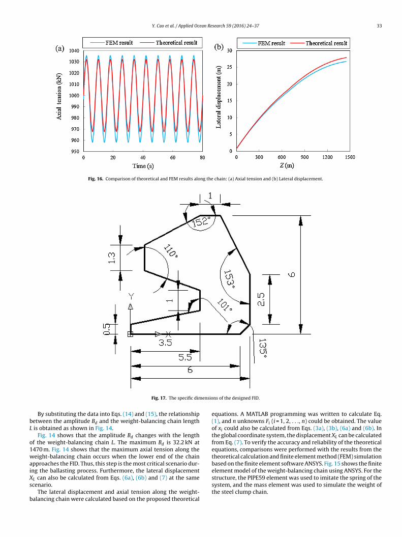
Fig. 16. Comparison of theoretical and FEM results along the chain: (a) Axial tension and (b) Lateral displacement.
ensio
bL
o1waiXs
b
Fig. 17. The specific dim
By substituting the data into Eqs. (14) and (15), the relationshipetween the amplitude Bd and the weight-balancing chain length
is obtained as shown in Fig. 14.Fig. 14 shows that the amplitude Bd changes with the length
f the weight-balancing chain L. The maximum Bd is 32.2 kN at470 m. Fig. 14 shows that the maximum axial tension along theeight-balancing chain occurs when the lower end of the chain
pproaches the FID. Thus, this step is the most critical scenario dur-ng the ballasting process. Furthermore, the lateral displacement
L can also be calculated from Eqs. (6a), (6b) and (7) at the samecenario.The lateral displacement and axial tension along the weight-alancing chain were calculated based on the proposed theoretical
ns of the designed FID.
equations. A MATLAB programming was written to calculate Eq.(1), and n unknowns Fi (i = 1, 2, . . ., n) could be obtained. The valueof xi could also be calculated from Eqs. (3a), (3b), (6a) and (6b). Inthe global coordinate system, the displacement XL can be calculatedfrom Eq. (7). To verify the accuracy and reliability of the theoreticalequations, comparisons were performed with the results from thetheoretical calculation and finite element method (FEM) simulationbased on the finite element software ANSYS. Fig. 15 shows the finiteelement model of the weight-balancing chain using ANSYS. For the
structure, the PIPE59 element was used to imitate the spring of thesystem, and the mass element was used to simulate the weight ofthe steel clump chain.
34 Y. Cao et al. / Applied Ocean Research 59 (2016) 24–37
Table 2Weight-balancing chain parameters.
Parameters Quantity
Steel clump chain Nylon rope
Diameter (mm) 431 300Length (m) 100 1370Dry density (kg/m3) 7850 1030Minimum break load (kN) >10,000 >10,000Modulus (GPa) 210 30CD 1.3 1.3CM 2.0 2.0
Table 3Comparison of results.
Item Maximum lateraldisplacement (m)
Vibrationamplitude (kN)
Maximum axialtension (kN)
Theoretical result 27.9 32.2 1032.2
wlauiFrtmrmwoaloratlsi
w
Table 4Parameters of the main components.
Parameter Quantity
DSIM WWIM SIM PIM PBM
Diameter (mm) 300 300 300 300 300Length (m) 1470 1470 1470 1470 1470Dry density (kg/m3) 7850 7850 7850 1030 7850Minimum break load (kN) >10,000 >10,000 >10,000 >10,000 >10,000Modulus (GPa) 210 210 210 75 210
TR
TS
FEM result 26.7 38.7 1035.7Difference (%) 4.2 20.2 0.3
Next, time-domain analysis was performed by coupling theave force and the ocean current force. The simulation results of
ateral displacement and axial tension were also obtained. Fig. 16(a)nd (b) compare the proposed theoretical calculation and FEM sim-lation results. As shown in Fig. 16(a), the variation in axial tension
s related to the heave motion of the lowering point. Although theEM result for vibration amplitude differs slightly from the theo-etical result, the two results coincide well. Fig. 16(b) shows thathe value of lateral displacement increases with water depth; the
aximal value occurs at 1450 m water depth. Table 3 compares theesults for maximum lateral displacement, vibration amplitude and
aximum axial tension. As shown in Table 3, the FEM results matchell with the results of the proposed method. Thus, the validity
f the proposed theoretical equations is verified. The maximumxial tension is approximately 1032.2 kN and the minimum breakoad of the nylon rope is 10,000 kN, thus ensuring a safety factorf 9.69. Furthermore, to install the 250 t SPS in the same envi-onmental conditions, the lateral displacement and axial tensionlong the main components (e.g., the drill pipe or winch wire) ofhe abovementioned mainstream installation methods were calcu-ated according to FEM. The parameters of the main components are
ummarised in Table 4, and the simulation results are summarisedn Table 5.As shown in Table 5, the maximum axial tension along theeight-balancing chain in the proposed method is considerably
able 5esults of different methods.
Methods Maximum lateral displacement (m)
Proposed method 26.7
DSIM 16.2
WWIM 8.7
SIM 12.1
PIM 6.7
PBM 9.3
able 6eries product performance.
Term Type Density (g/cm3) Compressive s
Standard performance SBM-035 0.35 ± 0.02 ≥8
SBM-048 0.48 ± 0.02 ≥25
SBM-053 0.53 ± 0.02 ≥45
High performance SBM-H038 0.38 ± 0.02 ≥15
SBM-H050 0.50 ± 0.02 ≥45
SBM-H070 0.70 ± 0.02 ≥90
CD 1.3 1.3 1.3 1.3 1.3CM 2.0 2.0 2.0 2.0 2.0
smaller than in other mainstream installation methods wheninstalling the 250 t SPS at a water depth of 1500 m because the bal-last can be deployed in more than one batch. The comparison resultsprove that the proposed method greatly reduces the requirementfor the surface vessel crane and cable capacity. Moreover, the vibra-tion amplitude along the weight-balancing chain is reduced by over60% in the numerical example, which indicates that the proposedmethod can reduce the influence of the wave and ocean currentforces on axial tension. However, in the proposed method, the lat-eral displacement of the weight-balancing chain at 1450 m belowthe water surface is 26.7 m, which is larger than in the other meth-ods. The reason is that the ballast is deployed in two batches, andthe nylon rope bears only 100 t weight each time, whereas in theother methods, the main bearing carrier (such as the winch wire ordrill pipe) is directly connected to the SPS and bears 200 t at once,which makes the weight-balancing chain more easily affected byocean environments.
4.2.2. Dynamic response of the FID under irregular waveIn the process of set down, the wave load has a prominent
effect on the hydrodynamic response of the assembly of FID andSPS within a certain depth. Compared to hydrostatic pressure,dynamic response is a major issue that should be considered inshallow water. The wave load decreases with increasing penetra-tion depth into the water of the assembly, and thus its influence onthe dynamic response also decreases. In deep water, the wave loadhas little effect on the assembly, and the hydrostatic pressure is ofmajor concern. Using the water dynamic analysis software AQWA,a single-tug installation system, including a deployment vessel and
the assembly, was established. The dynamic response of the systemwas analysed in the process of set down. The specific dimensionsof the designed FID for installing the 250 t SPS at a water depth ofVibration amplitude (kN) Maximum axial tension (kN)
38.7 1035.7107.5 2369.9186.4 2489.9129.5 1391.9163.2 2017.5178.9 2478.4
trength (MPa) Water absorption rate (%/day) Depth (m)
≤3 100≤3 2000≤3 4500
≤3 1000≤3 4500≤3 Full depth ranges

an Research 59 (2016) 24–37 35
1o
otoiw(suf3o
Y. Cao et al. / Applied Oce
500 m are given in Fig. 17. Fig. 18 shows the finite element modelf the single-tug installation system.
The FID mainly consists solid buoyant material. The propertiesf the products produced by the Marine Chemical Research Insti-ute are given in Table 6 for reference. The label shows the densityf the product. Table 6 provides a partial list of the products. To
nstall the SPS at a water depth of 1500 m, the product “SBM-048”ith low density (0.48 ± 0.02 g/cm3), high compressive strength
25 MPa) and low water absorption rate (less than 3%/day) was cho-en as the solid buoyant material. The chosen material can be used
nderwater as deep as 2000 m, and thus the strength requirementsor the installation can be met. The elastic modulus of the material is0 GPa. The volume of the FID is 507 m3, which can provide 263.6 tf buoyancy.
Fig. 18. Single-tug installation system.
Fig. 19. Relationship between the FID’s penetration depth into the water of and its maximum motion response values: (a) motion, (b) velocity and (c) acceleration.

36 Y. Cao et al. / Applied Ocean Research 59 (2016) 24–37
tages:
ccrtara
wFuaFrids
tptFt(cs
lwspoti
Fig. 20. Tension along the ballasting control chain vs. time at four s
In the process of set down, the swaying motion of the FID isonstrained by the two control chains. However, the wave load mayause large heaving and pitching motions of the FID. The motionesponse analysis of the FID was started from the state in whichhe FID was only immersed in water. Note that the lowering speednd vessel motion were ignored in the analysis. Fig. 19 shows theelationship between the FID’s maximum motion response valuesnd its penetration depth into the water.
As shown in Fig. 19, the motion response of the FID decreasesith increasing penetration depth into water by the FID. When the
ID is only immersed in water, the maximum motion response val-es are large because of the wave load. The values of the heavingnd pitching motions reach 1.1 m and 3.4◦, respectively. When theID’s penetration depth into water is more than 50 m, the motionesponse values are approximately small constants, which can begnored. The process of set down usually occurs at a certain waterepth, and the wave load has a small effect on the FID. Thus, thetability of the FID under wave load is guaranteed.
The motions of the FID will cause a dynamic response of theension along the ballasting control chain. Four stages during therocess of set down were chosen for dynamic response analysis ofhe tension along the ballasting control chain in time-domain: theID at water depths of 10 m (beginning to set down), 50 m (leavinghe splash zone), 500 m (entering the deep water area) and 1450 mpreparing to land). The variations in tension along the ballastingontrol chain with time at all four stages were thus obtained ashown in Fig. 20.
Fig. 20 shows that the tension and dynamic response of the bal-asting control chain decrease as the FID’s penetration depth into
ater increases. When the FID enters a deepwater area, the ten-ion is approximately a constant. The maximum tension during therocess is approximately 37.6 kN, with the FID at a water depth
f 10 m, much smaller than in other methods. On the other hand,he hydrostatic pressure increases with water depth and reachests maximum when the FID is at a water depth of 1450 m. Thus,FID at water depths of (a) 10 m, (b) 50 m, (c) 500 m and (d) 1450 m.
these two stages are the most critical scenarios in the process of setdown.
5. Conclusions
The FID was designed in this study for installing the SPS. The FIDhas a lower density than water, which can provide buoyancy to theSPS. Hence, the new installation method using the FID can installlarge subsea structures without a heavy-lift vessel. The new methodis cost effective compared with installation methods that utilisespecialised deep-water installation vessels. Furthermore, the FIDcan minimise the effect of dynamic loading, such as waves and cur-rents, throughout the transportation and installation stages, andthus, the proposed method can adapt to hostile environments.
In this study, a numerical analysis of the set down and bal-lasting processes at a water depth of 1500 m was performed todemonstrate the feasibility and advantages of the FID. Theoreticalcalculations were conducted to analyse the lateral displacementand axial tension along the weight-balancing chain. Meanwhile, anFEM analysis based on ANSYS was employed to analyse the dynamicbehaviour of the chain. The results from the theoretical calculationand the ANSYS simulation exhibited good agreement, which veri-fied the validity of the theoretical method. Based on the proposedmethod and the ANSYS simulation, the lateral displacement andaxial tension along the main components of the other mainstreaminstallation methods were also calculated. The comparison of theresults showed that the proposed method significantly reduces theinfluence of environmental factors and installation conditions. Fur-thermore, hydrodynamic analysis was performed using AQWA andthe tension along the ballasting control chain during the processof set down was calculated. The motion response of the FID wasalso computed. The results verified that the proposed method could
effectively reduce tension and dampen the dynamic response of theFID.Based on these results, the FID ideally satisfies the growingdemand for installing large structures in deep water.

an Re
A
Ft12t
R
[
[
[
[
[
[
[
[
[
[
[
[
[22] M.B. Cerqueira, F.E. Roveri, L.E. Peclat, E.L. Labanca, The need for thependulous installation method, in: Proceedings of the 25th InternationalConference on Offshore Mechanics and Arctic Engineering, Jun 4–9; Hamburg,
Y. Cao et al. / Applied Oce
cknowledgments
This work has been supported by the National Natural Scienceoundation of China (Contract No. 11472309), the Fundamen-al Research Funds for the Central Universities (Contract No.4CX02208A), the State Key Laboratory of Robotics (Contract No.013-O15) and Key Research Projects of Shandong Province (Con-ract No. 2015GSF115024).
eferences
[1] F.E. Roveri, L.V.S. Sagrilo, E.C.P. De Lima, F.B. Ciciia, Comparing measured andcalculated forces of a manifold deployment in 940 meters water depth, in:Proceedings of the 22nd International Conference on Offshore Mechanics andArctic Engineering, 2003 June 8–13; Cancun, MEX. New York: ASME Press,2003, p. 37114.
[2] F.E. Roveri, M.C. De Oliveira, M.J. Moretti, Installation of a productionmanifold in 2000 ft water depth offshore Brazil, in: The 1996 OffshoreTechnology Conference, May 6–9; Houston, USA, 1996.
[3] P.F.K. Stock, M.B. De Cerqueira, F.E. Roveri, A new method for deployingsubsea hardware in deep water, in: Proceedings of the 2002 Deep OffshoreTechnology Conference, Nov 13–15; New Orleans, La. New Orleans, La: DOTPress, 2002.
[4] J.M.T. De Gam Lima, M.L. Kuppens, P.F. Da Silveira, P.F.K. Stock, Developmentof subsea facilities in the Roncador field, in: The 2008 Offshore TechnologyConference, 2008 May 5–8; Houston, USA, 2008.
[5] A.M. Wang, Y. Yang, S.H. Zhu, H.L. Li, J.K. Xu, M. He, Latest progress indeepwater installation technologies, in: Proceedings of the Twenty-second(2012) International Offshore and Polar Engineering Conference, June 17–22;Rhodes, GRE, 2012.
[6] Y.Y. Wang, M.L. Duan, W. Feng, D.G. Wang, J.P. Liu, K.Y. Zeng, Investigation oninstallation methods of deepwater manifolds and their applications to LW3-1gas field in South China Sea, Ocean Eng. 29 (August (3)) (2011) 23–30.
[7] J. Zhang, Y. Xie, Research and development of subsea manifold installationmethods, Ocean Eng. 29 (February (1)) (2011) 143–148.
[8] F.E. Roveri, M.B. Cerqueira, R.D. Machado, P.F.K. Stock, The utilization of thependulous motion for deployment subsea hardware in ultra-deep water, in:Proceedings of the 2005 Deep Offshore Technology, Nov 8–10; Vitoria, Brazil,
2005.[9] A.C. Fernandes, C.R. Neves, J.S.S. Junior, The concomitant model testingapproach for the development of the pendulous installation method of heavydevices in deep water, in: Proceedings of the 26th International Conference onOffshore Mechanics and Arctic Engineering, Jun 10–15; San Diego, USA, 2007.
[
search 59 (2016) 24–37 37
10] A.M. Wang, S.H. Zhu, X.H. Zhu, J.K. Xu, M. He, C.J. Zhang, Pendulousinstallation method and its installation analysis for a deepwater manifold inSouth China Sea, in: The 2013 International Offshore and Polar EngineeringConference, Jun 30–Jul 5; Anchorage, USA, 2013.
11] T. Risoey, H. Mork, H. Johnsgard, J. Gramnaes, The pencil buoy method: asubsurface transportation and installation method, in: The 2007 OffshoreTechnology Conference, Apr 30–May 3; Houston, USA, 2007.
12] H. Mork, J. Lunde, A cost-effective and safe method for transportation andinstallation of subsea structures: the pencil buoy method, in: The 2007Society of Petroleum Engineers, Sep 4–7, Scotland, UK, 2007.
13] R. Nelson, J. Soliah, T. Caldwell, D. Morrison, J. Pritchard, Heave compensatedlanding system—a novel tool for subsea intervention, in: The 1997 OffshoreTechnology Conference, May 5–8; Houston, USA, 1997.
14] A. Joensen, D. Paul, A low tech, low risk system for the installation of largestructures in deep water, in: The SPE Offshore Europe Oil and Gas Conference,Sep 6–8; Aberdeen, UK, 2011.
15] Y. Bai, W.S. Ruan, S. Yuan, X. He, J.B. Fu, 3D mechanical analysis of subseamanifold installation by drill pipe in deep water, Ship Offshore Struct. 9(January (3)) (2014) 333–343.
16] F.R. Driscoll, R.G. Lueck, M. Nahon, Development and validation of alumped-mass dynamics model of a deep-sea ROV system, Appl. Ocean Res. 22(June (3)) (2000) 169–182.
17] X.J. Lin, W.S. Xiao, H.Y. Wang, Drill string mechanical analysis of running deepwater oil tree, J. China Univ. Petrol. 35 (October (5)) (2011) 125–129.
18] H. Jiang, W.D. Ruan, H.D. Qiao, W.J. Qian, Y. Bai, Mechanical analysis of subseamanifold lowered into deep water, Ship Eng. 35 (August (4)) (2013) 108–112.
19] L.L. Yao, Research on Hydrodynamic Analysis of Large-scale Subsea Facility inDeepwater Installation [Master’s Thesis], Shanghai Jiao Tong University,Shanghai, 2011.
20] R. Yttervik, S.A. Reinholdtsen, C.M. Larsen, G.K. Furnes, Marine operations indeep water and a variable current flow environment, in: Proceedings of the3rd International Conference on Hydroelasticity in Marine Technology, Sep15–17, Oxford, UK, 2003.
21] K.H. Halse, V. Æsøy, D. Ponkratov, Y.G. Chu, J.F. Xu, E. Pedersen, Liftingoperations for subsea installations using small construction vessels and activeheave compensation systems: a simulation approach, in: Proceedings of theASME 2014 33rd International Conference on Ocean, Offshore and ArcticEngineering, Jun 8–13; San Francisco, USA, 2014.
Geramny, 2006.23] W.D. Qiu, Mechanics of Vibration, China Univ Petrol Press, Qingdao, 2001.