applied environmental technology development …/67531/metadc703375/...wsrc-ms-2000-00172 22...
TRANSCRIPT

WSRC-MS-2000-0017222 February 2000
page 1 of 16
Applied Environmental Technology Development at the Savannah River Site:A Retrospective on the Last Half of the 20th Century
Brian B. LooneySavannah River Technology Center
Aiken SC 29808
Introduction
Fifty years ago, the Savannah River Site (SRS) was built to produce nuclear materials. These
operations impacted air, soil, groundwater, ecology and the local environment. Throughout its
history, SRS has addressed these contamination issues directly and has maintained a strong
commitment to environmental stewardship. The site boasts many environmental firsts. Notably,
SRS was the first major DOE facility to perform a baseline ecological assessment. This
pioneering effort, by Ruth Patrick and the Philadelphia Academy of Sciences, was performed
during SRS planning and construction in the early 1950’s. This unique-early example sets the
stage for subsequent efforts. Since that time, the scientists and engineers at SRS have proactively
identified environmental problems as they occurred and have skillfully developed elegant and
efficient solutions.
On a personal note, I am proud to represent the outstanding environmental scientists of the
Savannah River Technology Center (SRTC, formerly the Savannah River Laboratory). Former
employees such as Wendall Marine, James Fenimore, Henry Horton, Ed Albenesius, Bill Reinig
and Todd Crawford, and current scientists such as Jack Corey, Al Boni and Chas Murphy have
served as role models and are my mentors. From these individuals, I learned that developing
solutions to environmental problems requires honesty, simplicity, technical creativity and hard
work.
The SRTC approach relies an interdisciplinary team of scientists – geologists, engineers, chemists,
mathematicians, and others. The solutions developed by the team are based on focused
environmental characterization followed by selecting and deploying clean-up technologies that are
WSRC-MS-2000-0017222 February 2000
page 2 of 16
matched to the problem. Each technological advance is grounded in a clearly stated conceptual
model and is developed and refined using the scientific method. Successful technologies always
obey natural laws, and often rely on natural processes or capabilities. These are the values that
were instilled in me during my career in SRTC, and these are the values that I will try to
communicate to you using a few examples below. Many of these technologies, consistent with
the recent focus on partnerships with the community, have been transferred to the public for use
in solving our nations environmental challenges.
Anatomy of a Contaminated Site
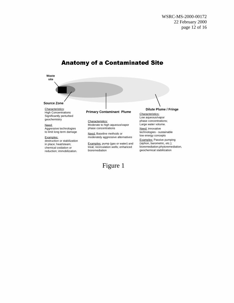
Figure 1 depicts a conceptual diagram of a contaminated site that has impacted its surroundings –
in this case, the underlying soil and groundwater. The three ovals – the source zone, the primary
contaminant plume, and the dilute fringe – represent different portions of the impacted
environment that each has a different character. The source zone contains significant
contamination in concentrated and hazardous forms. The source zone can contain materials such
as undissolved organic liquids (oils, fuels or solvent), strong acids or bases, high levels of
radiation, and/or toxic chemicals or elements. The second oval, the primary contaminant plume, is
comprised of contaminated groundwater or vapor than carries pollutants at lower levels, but
levels that still represent a potentially significant present or future hazard. The third oval, the
dilute fringe, contains contamination at relatively low concentrations, but in large volumes of
water.
Efficient and effective environmental clean up requires matching the character of the clean-up and
stabilization methods to the character of the target zone of contamination. Thus, aggressive and
relatively expensive methods are often appropriate for the source zone, classical pump-and-treat
methods are often good for the primary contamination zone, and various methods based on
natural processes are often best for the dilute fringe. Figure 1 identifies several example
technologies that are appropriate for each of the ovals.

WSRC-MS-2000-0017222 February 2000
page 3 of 16
In Figure 2, I have extended this conceptual model by identifying the cost basis for the typical
clean up technologies. In the source zone, stabilization and removal methods are normally priced
in terms of volume of soil or amount of contaminant in the treatment zone ($ per cubic yard, $ per
pound and the like). The reference source zone technologies require aggressive access and
subsequent use of targeted energy or chemical reagents. It is clear that in the source zone it is
important to characterize the site in such a way that the precise location of the source zone is
delineated as carefully as possible. This approach will reduce costs by focusing energy or reagent
to areas where they are needed. Equally important, however, is a desire to minimize of any
undesired negative impacts (wasting energy, harming microbiological populations, etc.) associated
with using aggressive remedies on regions without source level contamination. Similar to a
doctor, environmental scientists should “first, do no harm.”
In the primary contaminant plume, treatment technologies are normally priced in terms of the
amount of water (or vapor) treated ($ per gallon and the like). Thus, the goal of characterization
is to define the flow directions and general plume structure to allow the most contaminant to be
treated in the fewest “gallons”. Figure 3 illustrates an important-final extension to our simplified
conceptual model. This diagram of the primary contaminant plume at the SRS metals fuel and
target fabrication facility (M Area) shows that contamination moves in response to many factors –
contaminant release location and type, geology, sources and discharges of water, and many
others. The resulting contaminated soil and groundwater zone occupies a complicated three-
dimensional shape rather than the simple ovals that we began with. This complexity must be
recognized when developing and implementing technologies for both characterization and clean
up of the primary contaminant plume.
The dilute fringe contains low concentrations of contamination in large volumes of water. Thus,
the best technologies for this zone are those that are priced in terms of time ($ / year and the like).
To be successful, these technologies must rely on natural-sustainable-measurable processes. This
class of technology has gained recent regulatory support under the terminology “monitored
natural attenuation”. For the dilute fringe, technology selection is biased toward understanding

WSRC-MS-2000-0017222 February 2000
page 4 of 16
the contaminant destruction and stabilization capabilities of native species and natural populations.
A second step is identifying engineering interventions, if needed, to maximize the performance
and to assure that the attenuation process will operate for extended periods. A critical
requirement for these technologies development of logical and cost-effective monitoring
strategies.
The three zones depicted in Figure 1 are present at contaminated sites of all sizes. At a “mom-
and-pop” gas station, the entire contaminated zone – all three ovals – might occupy a portion of a
city block. At a large industrial facility like the M Area at SRS, the contaminated zone can extend
over a few square miles. The size of a problem impacts how distinct the actions to address the
different zones need to be. Time is also a factor. Concentrations change, as cleanup progresses,
so that dilute fringe technologies become appropriate for polishing areas that were formerly at
higher concentrations.
Above, I have outlined a conceptual description of a typical class of environmental problem. The
description is simple and valuable. It provides clarity in defining what technologies are really
needed. It helps us describe our cleanup plans to regulators and interested citizens. It encourages
implementation of a suite of technologies – each targeting a problem that it is efficient and
effective in addressing.
In the sections below, I highlight how this relatively simple conceptual model of the anatomy of a
contaminated site can be the basis for improved environmental technologies. I have summarized
examples of improved subsurface access methods, novel characterization techniques, and
improved cleanup technologies for each of the ovals.
Source Zone Diagnosis and Treatment
As described above, it is critical to locate the concentrated and hazardous contaminants in the soil
and shallow groundwater in the source zone. Data from most sites indicates that source zone

WSRC-MS-2000-0017222 February 2000
page 5 of 16
contaminants accumulate in thin-highly-concentrated layers – these layers can be only inches
thick. Some contaminants concentrate near the point of release (many metals and radionuclides);
others can move downward and concentrate at depth as they interact with hydrogeological
features such as clay layers or the water table. The resulting challenge for characterization is to
develop and use a strategy that defines these discrete intervals for a reasonable cost. Using
traditional methods, namely drilling a few holes with limited numbers of expensive samples, has a
high potential to miss the thin accumulation zones. While the samples may have a legal pedigree,
such an approach does not efficiently support environmental decisionmaking/engineering.
We have proposed a “toolbox” approach that uses technologies ranging from geophysics (looking
at the reflection and transmission of energy through the soil) to traditional sampling. The heart of
the toolbox for source zones, however, is a group of technologies (sensors and samplers)
deployed by direct pushing, or insertion, into the ground (these methods have the generic name
cone penetrometer (CPT), and trade names such as GeoProbe and SCAPs). These technologies
directly address the problem of the geometry of the expected contaminant distribution. Using
inexpensive sensors, CPT provides screening data throughout entire profile. The probability of
identifying the thin accumulation zones is maximized.
Early CPT sensors were primarily used for describing geology and were developed for
engineering and construction. These basic systems have been supplemented by an array of
sensors that provide (as needed) electrical measurements, chemical measurements using
spectroscopy or fluorescence (these use fiber optic lines to transfer light), direct viewing of the
soil using cameras, and many different samplers to collect water, soil or vapor. Several examples
are described on Table 1. In each case, the technology is targeted at delineation of the high
concentration source zone so that cleanup can be performed efficiently and safely.
Characterization of a source zone is a necessary step toward the goal of removal and/or
destruction. Appropriate classes of technologies to address source zone contamination include
enhanced removal, in situ (or in place) destruction, stabilization, and barriers. These classes can

WSRC-MS-2000-0017222 February 2000
page 6 of 16
be used alone or in combination. In collaboration with other DOE labs, federal agencies,
universities, and industry, all of these source remediation technology classes have been tested and
used (as appropriate) at SRS. With the exception of barriers, all of these technology classes
require the “injection and mixing” of energy or treatment chemicals into the source zone. Energy
based technologies used at SRS include electrical resistance heating, radio frequency heating, and
vitrification. A steam based remediation, known as Dynamic Underground Stripping, in
scheduled for full-scale use in 2000. Chemical based systems range from shallow soil mixing units
to reagent injection in wells. Figure 4 shows the operation of an example system in which
Fenton’s Reagent (hydrogen peroxide and reduced iron) was injected to destroy industrial
solvents in a target zone about 150 feet deep.
Primary Contaminant Plume – Stepwise Improvement of the Baseline
This zone is characterized by the presence of contaminants at easily measured and potentially
harmful. The contaminants in this zone tend to be somewhat mobile. As a result, baseline
methods, like “pump and treat” work reasonably well. Significant quantities of contamination can
be removed (either as soil vapor or groundwater) and the contaminants treated at the surface
using standard water treatment methods. Advancing the state of the art for this zone requires
attention to large-scale plume geometry and incorporation of creative-stepwise improvements in
engineering. SRS has made several significant contributions that improve primary contaminant
plume technologies. These contributions include improved depth discrete sampling devices (such
as the strata-sampler and the cone-sipper), improved data interpretation using 3D imaging
techniques, and successful deployment of innovative cleanup systems (recirculation wells and the
like). I have summarized two notable contributions below – environmental horizontal wells and in
situ bioremediation.
SRTC pioneered the use of horizontal wells for environmental cleanup. Environmental horizontal
drilling has roots in oil and gas exploration and in shallow pipeline/utility installation. As depicted
in Figure 3, the primary contaminant plume has a complicated 3D geometry. The option of
WSRC-MS-2000-0017222 February 2000
page 7 of 16
matching the geometry of a cleanup system to the geometry of the contaminant distribution using
directional drilling, while simple in concept, represents a major advance. Horizontal and
directionally drilled wells provide efficient access to contaminants, as well as a range of new and
interesting engineering options (intercepting contaminants as they reach facility boundaries,
cleanup underneath buildings…). SRTC installed and tested two environmental horizontal wells
in 1988 – these wells represent the birth of the industry. Currently, SRS has nine horizontal
environmental wells installed at several sites for a variety of uses. SRS research, combined with
efforts of others, has resulted in growth of a mature and active horizontal environmental well
industry and formation of a national technical and trade association.
SRTC innovations cleanup of the primary plume extend beyond optimizing geometry and
improving access to the contamination. SRTC research has documented that natural
microorganisms (bacteria, fungi, and the like) that are capable of destroying or stabilizing many
pollutants are present in virtually all soil and groundwater systems. SRTC is recognized as a
leading institution in developing and implementing methods to utilize this resource – putting these
organisms to work for us. We “pay” them by adjusting the natural conditions and providing
nutrients that are missing or limiting the rate of decontamination. In the case of gasoline and oil,
the beneficial bacteria and other microorganisms consume the pollutants as a primary food source.
To do this, they need oxygen, nitrogen and phosphorus. Injecting air (oxygen and nitrogen)
provides two of these nutrients. SRTC developed and patented a method of adding phosphorus
to air so that all of the important nutrients could be added inexpensively. This technology,
PHOSter�, has been widely licensed and is being used throughout the country to clean up sites
ranging from “mom and pop” gas stations to large industrial sites.
SRTC has also pioneered technologies to cleanup more challenging contaminants like industrial
solvents. While these compounds are not directly used as food, we can add appropriate foods
that encourage their destruction. Similar to PHOSter�, we developed a method based on adding
air as the carrier. In this case, the air includes trace levels of natural gas and nutrients. The
success of this technology has resulted in its licensing and use at a variety of sites across the
WSRC-MS-2000-0017222 February 2000
page 8 of 16
country. The success of the bioremediation methods developed by SRTC is a testament to the
scientific approach and conceptual model – that nature provides the basis for the best
environmental solutions.
Dilute Fringe – Green Technologies
In the dilute fringe, even more than in any the other zones, the concept of putting nature to work
for environmental cleanup central to success. Creative use of natural forces, natural laws, and site
specific conditions is the key to developing cost-effective solutions for low concentrations of
contaminant in large volumes of water. Properly configured, tides, weather patterns, gravity,
interfacial interactions, natural biological processes, and other basic forces supply energy and
mechanisms for contaminant destruction and stabilization. As discussed below, these processes
can be inexpensive and effective. Importantly, the goal of dilute fringe technologies should be to
reduce contaminant exposure (flux), to protect human and environmental health, and to monitor
the performance of the protection in a direct and cost-effective manner. I have highlighted two
SRTC developed examples of the “green” technologies that are needed to address the challenging
conditions in the dilute fringe – BaroBall� and Geosiphon�.
The BaroBall� is a remediation tool that uses variations in barometric pressure to extract
contaminants from or inject fresh air into the soil. Without the device, wells screened above the
water table inhale and exhale in response to the weather. Soil properties, depth and other factors
determine the amount of flow. The BaroBall� is a simple check valve that uses a ping-pong ball
to control flow. Consistent with the need for steady long-term cleanup of dilute fringe levels of
contamination, the device provides a reliable performance with minimal use of using energy and
minimal maintenance.
A similar creativity in using natural forces is embodied in the Geosiphon�. If left alone,
contaminated groundwater moves steadily from its source to a discharge point near a river.
Water is moving from higher head, or total pressure, to lower total pressure. The Geosiphon�

WSRC-MS-2000-0017222 February 2000
page 9 of 16
recognizes this reality and uses the simple concept of a siphon to exploit the pressure difference to
our benefit. The system connects the contaminated groundwater to the river through a large pipe.
Importantly, the system contains a treatment bed that purifies and detoxifies the water as it is
being siphoned. To operate the system, the large pipe is primed and then the valves are open.
Under the influence of gravity, the siphon extracts and treats the water without the need for a
pump or pumping power (Figure 5). The low concentrations in the dilute fringe result in a long
life for the treatment bed and the overall system is conceptually appropriate for this zone.
As demonstrated by the use of pin-pong balls and siphons, it is clear that environmental
technology solutions do not always need to be complicated. Particularly in the dilute fringe,
simplicity and creativity are needed. SRTC is studying the potential role of plants and
microorganisms near groundwater discharges to determine their potential for contributing to the
solution. Dilute fringe technologies must be technically based and must be able to be monitored
and documented.
Concluding Remarks
Similar to any large industrial facility, construction and operation of SRS resulted in many
significant adverse environmental impacts. Nonetheless, it would have been easy to write this
paper as a list of successes and statistics.
SRS has treated more than 3 billion gallons of groundwater, removed more that 800
thousand pounds of contamination from soil and groundwater…. SRS has
completed or is actively cleaning up more than 300 of its 500 contaminated acres….
SRS has been awarded nineteen environmental technology patents and many national
awards for its environmental accomplishments…. SRS is committed to meeting its
obligations under a wide array of environmental regulations – NEPA, RCRA,
CERCLA, NPDES…. The SRS Environmental Restoration Program has been the
most active and successful program in the DOE complex in incorporating new

WSRC-MS-2000-0017222 February 2000
page 10 of 16
technologies into its work to accelerate cleanup and reduce costs…. SRS provides
frequent and detailed public information on its environmental impacts…. SRS was a
charter federal facility designated as National Environmental Research Park…. SRS
is home to the preeminent ecological research center in the world – the University of
Georgia Savannah River Ecology Laboratory and a major office of the U. S. Forest
Service….
SRS applies creative, interdisciplinary approaches to developing inexpensive and robust
technologies. The result has been a steady stream of effective products. SRTC pioneered the use
of horizontal wells for cleanup, and has created and licensed important environmental samplers
and sensors. Barometric pressure, solar energy and microbiology all have been put to work.
Going far beyond hatching new ideas, SRS is also recognized as a leader in developing and
demonstrating new technologies. SRS has been instrumental in moving technologies, both those
developed on-site and off-site, to field deployment and into widespread use in the private sector.
Lists of progress and accomplishments for each identified “waste site”, as well as general
chronologies of SRS accomplishments are widely available. I chose, instead, to provide my
assessment of how SRS has achieved environmental progress – focusing especially on the
technology contributions of the site’s scientists and engineers. We are committed to continue the
fifty-year environmental technology legacy that has been entrusted to us.

WSRC-MS-2000-0017222 February 2000
page 11 of 16Table 1. Example CPT Characterization Technologies
The cone penetrometer (CPT) and similar techniques such as the GeoProbe directly push sensors and samplers into the soil and shallow groundwater. This is a photograph of a CPT truck developed by DOD and DOE for testing new environmental characterization methods. The examples discussed below represents a collaboration among scientists from government agencies, industries and universities.
Fiberoptic probes can be used with a CPT to measure chemicals and subsurface conditions. Spectroscopic measurements such as fluorescence (left picture) and raman (right pictures) can be related to chemical concentrations. Specialized sensors for a variety of uses have been developed, tested and deployed.The Geo VIS Probe, a video system developed by DOD to be deployed with the CPT, is used to acquire magnified images of the soil and groundwater at the tip passes. The instrument consists of a CCD color camera, lens/focusing system, and an light-emitting-diode (LED) illumination systemA variety of samplers can be deployed using a CPT --samplers are available that collect liquids, vapors, or solids. Many systems allow samples to be collected without withdrawing the equipment from the hole. The cone sipper (left picture) is an SRTC developed system used to collect vapor and liquid samples. In some cases, CPT can be used to install monitor in wells and other devices for long term use.Specialized measurements can also be made using CPT equipment. One example is the "permeability probe developed by industry (Science and Engineering Associates) Creativity is a key to developing tools to find thin layers of contaminant accumulation. This fabric tube, modified by SRTC, can be installed in an open hole (installed by CPT or by drilling). The tube wicks oily contaminants -- these release a dye and the stains on the retrieved fabric tube show the depth of contaminated layers.
WSRC-MS-2000-0017222 February 2000
page 12 of 16
$QDWRP\ RI D &RQWDPLQDWHG 6LWH
Source Zone
Characteristics:High ConcentrationsSignificantly perturbedgeochemistry
Need:Aggressive technologiesto limit long term damage
Examples:destruction or stabilizationin place; heat/steam;chemical oxidation orreduction; immobilization.
Primary Contaminant Plume
Characteristics:Moderate to high aqueous/vaporphase concentrations
Need: Baseline methods ormoderately aggressive alternatives
Examples: pump (gas or water) andtreat; recirculation wells; enhancedbioremediation
Dilute Plume / FringeCharacteristics:Low aqueous/vaporphase concentrations;Large water volume.
Need: innovativetechnologies - sustainablelow energy concepts
Examples: Passive pumping(siphon, barometric, etc.);bioremediation;phytoremediation,geochemical stabilization
Wastesite
Figure 1

WSRC-MS-2000-0017222 February 2000
page 13 of 16
Figure 2
'LDJQRVLV DQG 7UHDWPHQW RI D
&RQWDPLQDWHG 6LWH
Source Zone
Costs:$/lb contaminant or $/cuyd. Removalexamples:< $50-$100/cu yd or< $100/lb for chlorinatedsolvents
hot spot characterizationreduces cleanup volume
Primary Contaminant Plume
Costs:$/treatment volume (gallon/cu ft)example:<$0.5-$10 / 1000 gallons
zone of capture characterizationneeded, optimize extraction toreduce treatment volume
Dilute Plume/Fringe
Costs:Operation andmaintenance costs $/time
mass transfer and fluxcharacterization needed
Wastesite

WSRC-MS-2000-0017222 February 2000
page 14 of 16
Figure 3. Cut-away diagram showing the 3Dstructure of a real grooundwater plume

WSRC-MS-2000-0017222 February 2000
page 15 of 16
Figure 4. Fenton’s Reagent is added to asource zone to destroy NAPL in place. This
project was a cooperation between SRTCand industry.

WSRC-MS-2000-0017222 February 2000
page 16 of 16
ContaminatedGroundwater
PermeableTreatment
Media Screen
TreatedGroundwater
Ground Surface
Discharge Point(Area of LowerHyraulic Head)
Siphon Line
Treatment Cell
Figure 5. The SRTC GeoSiphon concept(right) and the installation of a GeoSiphon at
SRS (left)