applications of gps technology - gdam philippines · pdf fileconventional vs. gps surveying...
TRANSCRIPT

Surveying and Mapping Applications of GPS
Enrico C. Paringit. Dr. Eng.University of the Philippines
Training Center for Applied Geodesy and Photogrammetry
1

Outline of this Presentation
• Types of GPS surveys
• Standards and Specifications for GPS Surveys
• Operational Aspects of GPS Surveys
• Planning and preparing for Field Surveys
2

Conventional vs. GPS Surveying (1)
a. Conventional surveyingare performed usingtraditional precise surveying techniques and instruments--i.e., theodolites, total stations, and levels.– can be used to economically and accurately establish
or densify projectcontrol in a timely fashion.
– Quality control statistics and redundant measurements in networksestablished by these methods help to ensure reliable results.
– have the requirement for intervisibility between adjacent stations.
3

Conventional vs. GPS Surveying (2)
b. GPS surveying areused to establish or densifyproject control– quality control statistics and redundantmeasurements in
GPS networks help to ensure reliable results. – Field operations to perform a GPS surveyare relatively easy
and can generally be performed by one person per receiver, with two or more receiversrequired to transfer control.
– does not require intervisibility between adjacent stations. – must have visibility of at least four satellites during
surveying.– makes GPSinappropriate in areas of dense vegetation.
4

Types of Surveys with GPS According to Application
• Geodetic Control Surveys
• Vertical Control Surveys
• Structural Deformation Studies
• Photogrammetry (for control and positioning)
• Dynamic Positioning and Navigation
5

Geodetic Control Surveys
• A geodetic control survey consists of establishing the horizontal and vertical positions of points for thecontrol of a project or installation site, map, GIS, or study area.
• These surveys establish 3-dimensionalpoint positions of fixed monuments, which then can provide the primary reference forsubsequent engineering and construction projects.
• These control points also provide the basic frameworkfrom which detailed site plan topographic mapping, boundary demarcation, and construction alignmentwork can be performed.
6

GPS Levelling
• GPS levelling is more economical than standard levellingtechniques, but the accuracy is generally lower.
• As a comparison, the allowable misclosurefor spirit levelling is:– 1st order: 4 (mm) or 4cm in
100km 2-way levelling (0.4ppm), or 1.2cm in 10km (1.2ppm).
– 2nd order: 8 (mm) or 8cm in 100km (0.8ppm), or 2.5cm in 10km (2.5ppm).
– 3rd order: 12 (mm) or 12cm in 100km (1.2ppm), or 3.8cm in 10km (3.8ppm).
7

Photogrammetric Control Surveys
8

Operational Aspects of GPS Surveying (1)
• Training in the operation of GPS survey receiver hardware, and post-processing software, as well as being aware of calibration and test procedures
• Survey planning considerations are derived from:– The nature and aim of the survey project -->as for conventional
surveys.
– The unique characteristics of GPS, and in particular no requirement for station intervisibility -->a simplification in survey design.
– The number of points to be surveyed, the resources at the surveyor's disposal, and the strategy to be used for propagating the survey --> a logistical problem.
– Prudent survey practice, requiring redundancy and check measurements to be incorporated into the network design.
• .9

Operational Aspects of GPS Surveying (2)
• Field operations requirements:– Setup of antennas over predefined ground marks
– Simultaneous operation of two or more GPS receivers
– Coordinate data gathering operation so that data collected has the same time-tags, involves the same satellites, etc
– Common data collection over some observation session
– Coordinated demount of GPS antennas and transport to new stations
• Field data validation to:– Verify sufficient common data collected at all sites operating
simultaneously.
– Verify quality of data to ensure that acceptable results will be obtained.
– Where data dropout is high or a station has not collected sufficient data, reoccupation may be necessary.
10

Operational Aspects of GPS Surveyingc(3)
• Office calculations:– To obtain GPS solutions for single sessions or baselines.
– To combine the results of single sessions into a network solution.
– To incorporate external information (for example, local control station coordinates), and hence modify the GPS-only network solution.
– To transform the GPS results to the local geodetic datum, and to derive orthometric heights.
– To verify the accuracy and reliability of the GPS survey.
11

GPS Survey Planning• Careful planning maximises the chances of the survey
achieving the desired accuracy, within a reasonable time and to budget.
POINTS TO CLARIFY BEFORE HEADING OUT
• What is the purpose of the survey?
• What are the accuracy and reliability requirements?
• What resources are available?
• What previous surveys have been carried out?
• Are there any special (or unusual) characteristics of the project or in the project site?
• Is the surveyor suitably equipped (in the broadest sense of the word) to carry out the GPS survey for the client? 12

Elements of the GPS Survey Planning Process
• PROJECT DESIGN: involves project layout and network design, and is driven primarily by accuracy and station location / density requirements (defined by the client), productivity / economic considerations (of concern to the GPS surveyor), and standards and specifications (promoted by the geodetic control authority).
• OBSERVATION SCHEDULE: giving consideration to such factors as the number of GPS receivers, occupation time per site, number of sites per day, requirement for multiple station occupancy, etc.
• INSTRUMENTATION & PERSONNEL: instrumentation appropriate for the task, mainly driven by what may be available inhouse or what could be hired from outside the organisation. Also, adequately trained personnel are needed in order to carry out the survey and process the data.
• LOGISTICAL CONSIDERATIONS: issues such as transportation, special site requirements (e.g., power, intervisibility, etc.), and factors related to network design and observation scheduling such as the receiver deployment pattern, etc.
• RECONNAISSANCE: which may or may not be necessary, depending upon how "critical" the GPS stations are to be to the overall project, whether permanent marks will be established, etc.
13

Project Design
“The final network / project design is usually a compromisebetween technical requirements and economics, worked out within the framework of explicit recommended practices for GPS surveys “:
The surveyor must take the following factors into account:– Definition of the network: size and shape of the overall network, the
number of stations, station spacing, any intervisibility requirements, new and existing (known) stations.
– Spacing of the existing (known) stations: for what purpose are they intended? as a quality check, for densification of existing control, for the determination of transformation parameters, etc.
– Accuracy requirements (defined by client) and standards (defined by the geodetic control authorities), for both horizontal and vertical surveys.
14
Refinements to the Network Design
• Some intervisible stations may need to be included to define starting azimuths for subsequent conventional surveys.
• There may be several existing stations in the area which could be included in the GPS survey.
• There is generally no need to establish GPS stations to "connect" the main net to surrounding control unless distances are large. – Distance: 20-30km - "ambiguity-fixed" solution
– ambiguity-free" solution is generally weaker by a factor of 2 to 3 compared to the "ambiguity-fixed" solution.
• Certain baselines may be designated as primary ones, for example, the baseline(s) defining the axis of a tunnel or engineering structure.
15
Ambiguity Reviewed
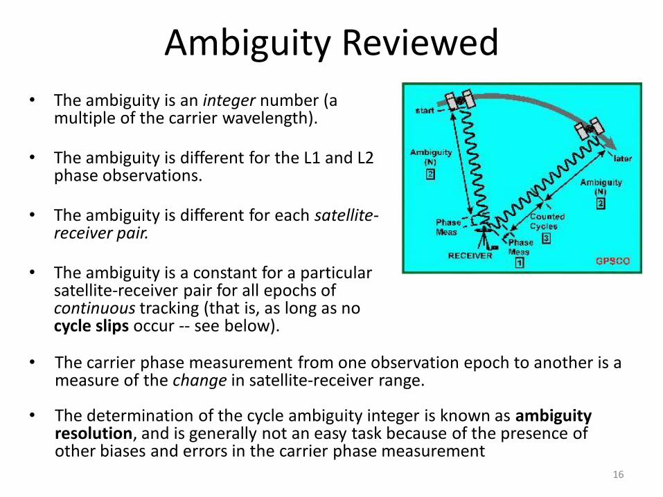
• The ambiguity is an integer number (a multiple of the carrier wavelength).
• The ambiguity is different for the L1 and L2 phase observations.
• The ambiguity is different for each satellite-receiver pair.
• The ambiguity is a constant for a particular satellite-receiver pair for all epochs of continuous tracking (that is, as long as no cycle slips occur -- see below).
• The carrier phase measurement from one observation epoch to another is a measure of the change in satellite-receiver range.
• The determination of the cycle ambiguity integer is known as ambiguity resolution, and is generally not an easy task because of the presence of other biases and errors in the carrier phase measurement
16

New, Old and Datum GPS stations • Surveying existing stations are expedient (save on establishing new
monumentation), and ties to previous work, or datum definition or the calibration of GPS heights
Geodetic control
Leveled site (benchmarks)
New controlReference point (e.g. PRS92)
17

Why New AND Known Stations?
• Required by the relevant GPS survey standards & specifications.
• For the determination of local transformation parameters between the GPS datum and the local geodetic datum.
• For quality control (QC) purposes
• In order to determine the geoid-spheroid separation
• In order to connect new GPS points into surrounding geodetic control
• However, a minimum of one known station must be used as the datum station in the GPS survey -- its coordinates must be known in the WGS84 system
18

Accuracy of New Stations:
• Required accuracy is defined by the project specifications, but the accuracy classification may be defined by GPS survey standards & specifications.
• Latitude is typically better determined than longitude. Height is worse than both.
• Typically, the horizontal coordinates are required in a local geodetic datum, and the vertical results in the orthometric height system.
• The accuracy of the GPS derived 3-D coordinates depend on the accuracy of the datum station(s) incorporated into the GPS solution (GPS phase solutions are relative, hence something has to be held fixed in WGS84).
• The final coordinate accuracy (in relation to the local geodetic datum) depends on the precision of the transformation between the GPS derived coordinates and the coordinates of the known stations in the local network.
• However, after transformation, the internal consistency (or precision) of the GPS results is unchanged.
• The final height accuracy depends on the precision of the height transformation: the geoid-spheroid separation, which can be determined in a number of ways
19

Accuracy of Known Stations:• GPS derived coordinate accuracy relative to
the local geodetic datum origin depends on– the datum station(s),
– the transformation process, and
– any secondary distortion of the GPS network resulting from fitting to the datum defined locally by the known geodetic stations.
• Note the following:– Datum station accuracy is generally defined by GPS survey standards &
specifications.
– Final transformed GPS coordinate accuracy depends on the quality of the transformation parameters
– If the GPS transformed results are also to be fitted into the surrounding control, the final transformed GPS coordinate accuracy and precision depends on the accuracy and precision of the known stations in the local geodetic system.
20
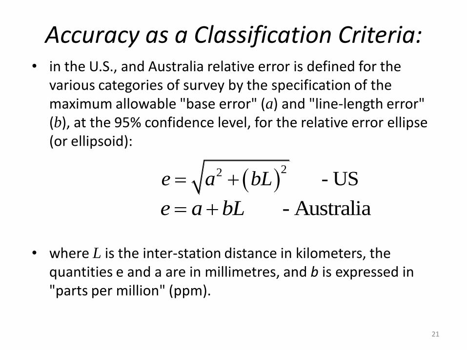
• in the U.S., and Australia relative error is defined for the various categories of survey by the specification of the maximum allowable "base error" (a) and "line-length error" (b), at the 95% confidence level, for the relative error ellipse (or ellipsoid):
• where L is the inter-station distance in kilometers, the quantities e and a are in millimetres, and b is expressed in "parts per million" (ppm).
Accuracy as a Classification Criteria:
22 - USe a bL
- Australiae a bL
21
GPS Classification accuracy
There are essentially two classifications for accuracy:
1. Internal: based on the minimally constrained adjustment of the GPS-only survey.
2. External: based on a constrained adjustment, where existing geodetic stations of the GPS network are held fixed to the published values of the terrestrial geodetic datum.
22

U.S. three-dimensional GPS survey accuracy classifications
ORDER-CLASS
Minimum geometric accuracy standard(95% confidence level)
a -- Base error (mm)
b -- Line-length error (ppm)
AA 3 0.01
A 5 0.1
B 8 1
1 10 10
2-I 20 20
2-II 30 50
3-1 50 100
23

Australian horizontal (2-D) surveyAccuracy Classification
ORDER-CLASS
Minimum geometric accuracy standard(95% confidence level)
a -- Base error (mm)
b -- Line-length error (ppm)
3A 0.2 2
2A 0.6 8
A 1.5 18
B 3 35
C 6 75
D 10 125
E 20 250
24

The Philippine Geodetic Control Network: Survey Standards
• Consists of 4 levels of control
DENR DAO Administrative Order No. 2007-29
25

Network Shape• There is an impact arising from "structural" considerations.
• Some networks are superior to others with regard to "strength".
• Only independent baselines contribute to network strength.
Network shapes: "wide" and "narrow"
26

Network strength= f(no. & location of independent baselines)
27

Observation Scheduling Considerations
• Those that relate to the satellitesthemselves: how many to observe, for how long, etc.
• Those that relate to satellite-receiver geometry.
• Those that relate to logistical design: number of observation sessions per day, number of multiple site occupancies, etc.
28

Satellite Considerations• Rise and set times of satellites above the
observing horizon of a site. (Due to atmospheric refraction modelling difficulties GPS satellites are not normally tracked at elevations less than 15°to 20° above the horizon.)
• Health of the satellites. Each satellite broadcasts a health status indicator within its Navigation Message.
• Satellite-site geometry: azimuth and elevation of satellites as a function of time.
• Information on the status of satellites for example, planned orbit manoeuvres, shutdowns, testing, new satellite launches, etc.
29

Tasks within the observation window scheduling
• Determine the minimum length of observation period per station. This is dependent on, amongst other factors, the following: – the satellite constellation to be observed,
– the length of the baseline,
– whether a "conventional" static GPS survey is being carried out, or "kinematic" and "rapid static" survey techniques will be used,
– the observation period, as some periods may have better "geometric strength" than periods of the same length at other times. (This is not an important issue for "conventional" GPS surveys, but it is important for modern "kinematic" techniques.)
• Determine the satellites to be observed by all simultaneously operating GPS receivers.
30

Factors in Specifying GPS Observation Length (1)
• The minimum number of satellites that must be observed simultaneously by GPS receivers is two (to form one double-difference observable).
• The more satellites observed simultaneously, the shorter the observation period can be.
• The shorter the observation session, the more care is needed to guard against multipath and other biases.
• The "total" satellite geometry (all satellites tracked over a session) has an important bearing on the quality of the results.
• The preferred solution is an "ambiguity-fixed" solution, hence any tracking beyond that required to successfully resolve the integer cycle ambiguities is useless.
31
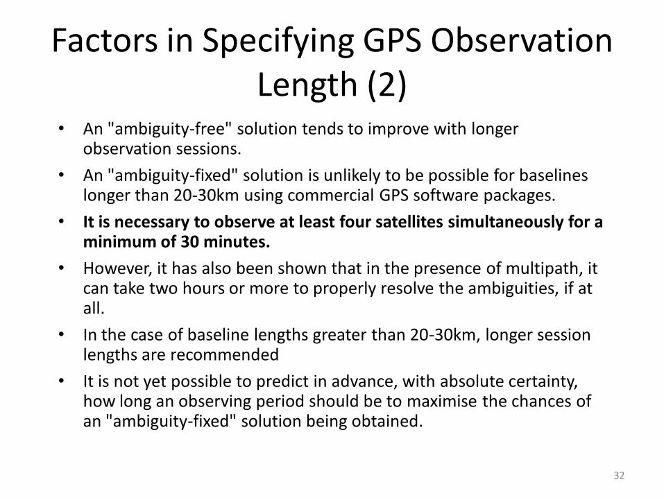
Factors in Specifying GPS Observation Length (2)
• An "ambiguity-free" solution tends to improve with longer observation sessions.
• An "ambiguity-fixed" solution is unlikely to be possible for baselines longer than 20-30km using commercial GPS software packages.
• It is necessary to observe at least four satellites simultaneously for a minimum of 30 minutes.
• However, it has also been shown that in the presence of multipath, it can take two hours or more to properly resolve the ambiguities, if at all.
• In the case of baseline lengths greater than 20-30km, longer session lengths are recommended
• It is not yet possible to predict in advance, with absolute certainty, how long an observing period should be to maximise the chances of an "ambiguity-fixed" solution being obtained.
32
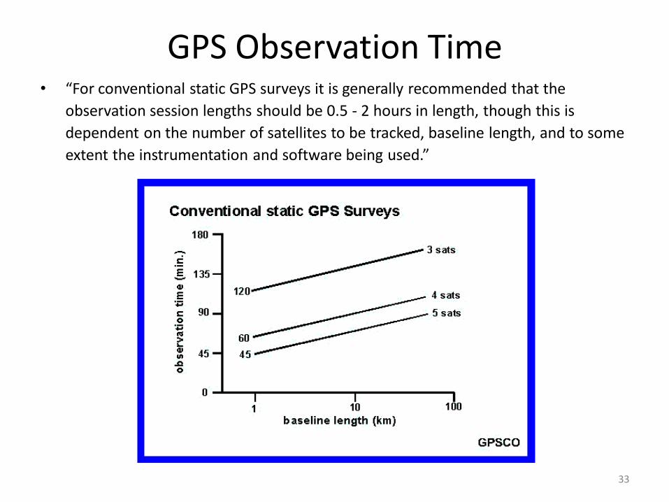
GPS Observation Time• “For conventional static GPS surveys it is generally recommended that the
observation session lengths should be 0.5 - 2 hours in length, though this is
dependent on the number of satellites to be tracked, baseline length, and to some
extent the instrumentation and software being used.”
33

Measures of Satellite Geometry
1. Measurement precision
2. Systematic errors present
3. Processing strategy used; and
4. The receiver-satellite geometry during the observing session
34
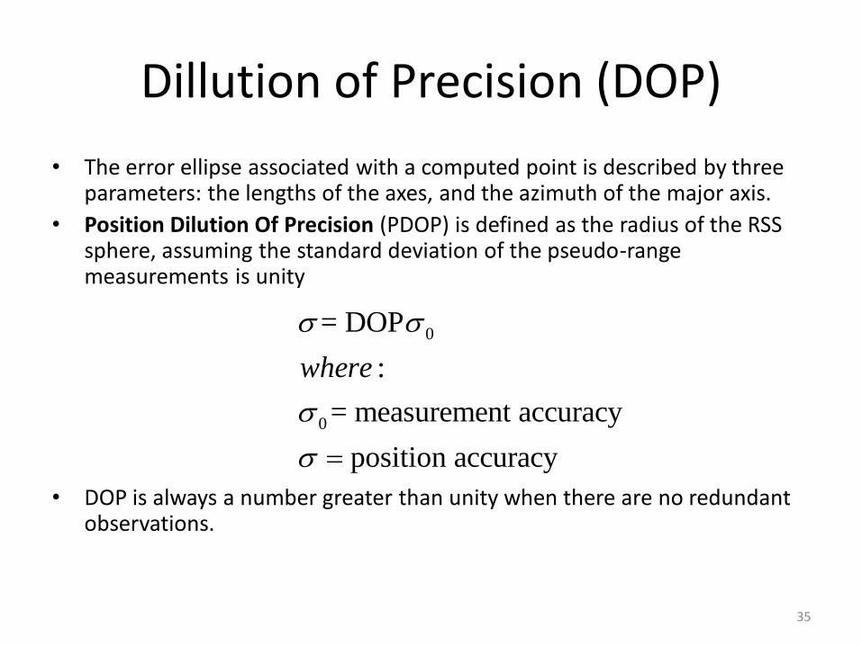
Dillution of Precision (DOP)
• The error ellipse associated with a computed point is described by three parameters: the lengths of the axes, and the azimuth of the major axis.
• Position Dilution Of Precision (PDOP) is defined as the radius of the RSS sphere, assuming the standard deviation of the pseudo-range measurements is unity
• DOP is always a number greater than unity when there are no redundant observations.
0
0
= DOP
:
= measurement accuracy
position accuracy
where
35

Sampling Dillution of Precision (DOP)There are a number of different definitions of DOP factors, depending on
the coordinate component, or combination of coordinate components, being considered:
2 2 2 2 2 2
2 2 2
2
2
2 2 2
2 2 2
2
:
, , = variances of the east, north and height components
, , = variances of the X, Y and Z components
= variance of
E N H X Y Z
E N T
H
T
E N H
X Y Z
T
PDOP
HTDOP
VDOP
TDOP
where
the estimated receiver clock
36

Sample Diurnal PDOP Plot
37

Why PDOP measure is notan appropriate indicatorfor GPS Surveying accuracy
• The navigation solution is based on the instantaneous satellite-receiver geometry, whereas
• PDOP gives the geometric strength of a point position, whereas the The pseudo-ranges are considered to be biased only by the errors of the receiver clock.
• the GPS carrier phase adjustment is governed by the continually changing geometry of an observing session which may last up to several hours.
• GPS carrier phase adjustment provides the relative positionof two or more receivers.
• In a GPS carrier phase adjustment, the double-differenced observation is predominantly biased by the integer cycle ambiguities (the satellite and receiver clock biases are eliminated).
38

So what constitutes a good tracking session?
• As a rule-of-thumb, a good session is one which has four or more visible satellitesabove the 15°- 20°elevation angle at the start of the tracking period, and ends before the fourth satellite sets below this cutoff elevation angle.
• The length of session then is a function of the baseline length, and whether it is a conventional static survey (say 30-120 mins in duration), or a "rapid static" survey (5-15 mins) or "stop & go" (<1 min).
39

Observation Scheduling: Some Logistical Factors
• The number of observation sessions in a day (dependent on length of the work day, and minimum session length).
• Total non-productive times: travel time between stations, station setup/takedown time, data downloading, etc.
• Number of occupations of each station(new and unknown).
40

Multiple Occupancy of Sites
• To provide a "link" in the datum between each session. How many common stations between sessions? – one is a bare minimum, – two provides one redundant link, and – three or more is even better.
• A quality control measure, as multiple occupancies provide different "pathways" through a network for checking on blunders, wrongly identified stations, errors in antenna height measurement, etc.
41
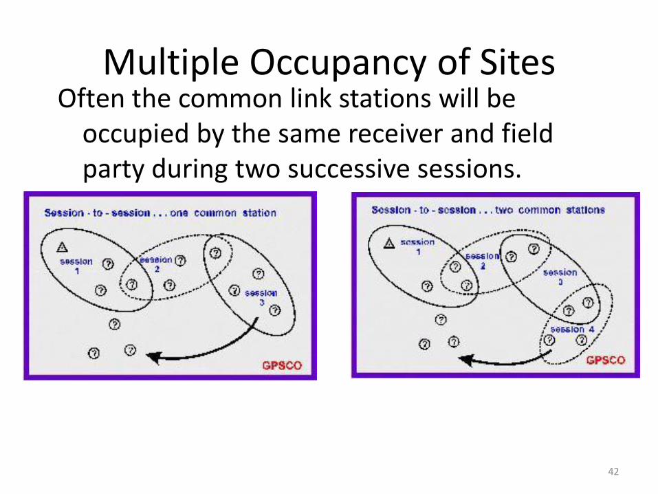
Multiple Occupancy of SitesOften the common link stations will be
occupied by the same receiver and field party during two successive sessions.
42

• The minimum number n of sessions in a network with s stations, using r receivers is (HOFMANN-WELLENHOF et al, 1998):
where o denotes the number of "link" or "pivot" stations between sessions, o1, r2, r>o and n is an integer.
An alternative relation that is simply based on the notion that all stations should have multiple occupancies
where m is the number of times a station must be occupied, and n must be rounded up to the next higher integer.
Number of Sessions in a Network
s on
r o
msn
r
43

INSTRUMENTATION & PERSONNEL CONSIDERATIONS
• Number of available GPS receivers: – the larger the number of receivers in a session, the larger the
number of directly connected stations, and hence a better network, faster progress and a less expensive survey.
• Receiver type:– all geodetic GPS receivers produce similar datasets and hence
similar final accuracies. – mixing different brands of receivers however can cause problems.
• Single or dual-frequency receivers:– dual-frequency instruments permit compensation for the
ionospheric delays on the GPS signals, hence they are essential for high accuracy applications, usually of little benefit for baselines <30km.
– dual-frequency instrumentation is generally necessary if modern "rapid static" survey techniques are being used.
– Mixing of single and dual-frequency receivers, as in the situation of mixing receiver types, is not recommended.
44
Pre-mission testing as part of the survey planning procedure
• Over a micro-network of several meters in extent, for example, a square or other regular figure, for which the "ground-truth" can be directly obtained by precise distance and/or angle measurement, or
• Over a special permanent test network, perhaps previously surveyed by GPS, or a zero-baseline, or
• An effective simulation of the planned survey, in which lines of similar length are surveyed using procedures close to those to be applied during the actual survey. This is the most expensive option.
45

LOGISTICAL CONSIDERATIONS
The logistical considerations of a GPS project increase enormously with:1. increase in the number of stations to be surveyed,
2. increase in the number of receivers deployed,
3. increase in the number of common stations occupied between sessions,
4. increase in the number of fixed stations to be occupied, and
5. increase in the number of sessions per day.
46

Receiver deployment schemes • A combination of the "base station" (or "radiation") mode, and the
"leap-frog" (or "traverse") mode is usually used
Leap frogging Traverse or “Spider”
47

Logistical Design Principles (1)
• Receiver deployment schemes based on:
– leap-frog mode
– base station operation
– or some combination of these.
• The "shape" of a GPS session, or final network (multi-session), plays little part in the final accuracy, unlike the situation with conventional surveys.
– Length of lines in a session do influence the final accuracy, both through the "ppm" relationship, as well as a change in the "ppm" value at distances above which ambiguity resolution can be carried out.
• Adjacent stations should be connected directly -- that is, keep baselines short.
• Stations on the perimeter of project area should be directly connected.
48
Logistical Design Principles (2)
• Connect all stations in network through "pivot" or "link" sites common to two or more sessions, so that a minimally constrained GPS network is established. – The percentage of multiple occupancies is directly related to the accuracy
classification of the survey• Maximise geometrical redundancy through having multiple occupancy of
sites (though only within reason). There are two types of redundancy: – Reoccupation of several sites at the same time to define repeat
baselines (to allow for checks on the internal consistency of GPS surveys). – Form loops of stations occupied during different sessions, permitting
checks on loop closure statistics. • Where possible sites should be revisited by different field parties, hence
ensuring independent setups, in order to minimise the chance of misidentifying the station mark.
• Avoid "no check" baselines where one station of the baseline has only been visited once.
49

Factors influencing GPS accuracy: Baseline results
• The "shape" of the GPS network is irrelevant as far as the baseline solution quality is concerned - orientation of baseline does not greatly influence its quality!
• The following factors do influence baseline quality:
– Length of baseline
– Single or dual-frequency instrumentation
– Length of observation session
– Number of observed satellites
– Observable being processed
– Processing software
– Quality of ancillary information (orbits, fixed sites, etc.).
50

GPS Survey ReconnaissanceReconnaissance issues for GPS surveying include:
– Satellite availability: satellite selection, satellite health, observation window, etc.
– Satellite visibility: checking on site obstructions.
– Clearly identifying the groundmarkover which the GPS antenna is to be set up. Particularly for night observations.
– Identifying, if necessary, eccentric stations to be occupied if the primary groundmark cannot be used, and other azimuth stations if required.
– Station access: critical for minimising non-productive travel times and unscheduled delays in getting on-site. Particularly important if night travel is involved.
– Site conditions: on-site power? multipath environment?
51
GPS Survey Reconnaissance
52

SATELLITE AVAILABILITY AND VISIBILITY
To schedule a GPS survey the following factors need to be taken into account:– Satellites are not normally tracked below an elevation of 15° to 20°
due to large atmospheric refraction errors at low elevation angles.
– There is a 24 hour observation window for GPS.
• At least 30 minutes of four (or more) satellite coverage is the accepted norm for standard static GPS surveys. There are periods when many more satellites are visible.
• The satellites' positions in the sky are predictable. They can be computed and output in a convenient graphical form, and taken out into the field during reconnaissance.
• A popular representation of satellite availability is the skyplot,
53

SkyplotSkyplot is a utility to plot satellite tracks on a zenithal projection centred at the
GPS ground station. The satellite azimuth and elevation is shown as a function of time.
Skyplots can be used during reconnaissance to ensure that the satellite signals from the selected satellites can be acquired by the receiver.
54

Skyplots• The obstructions at a site can be plotted on a zenith plot
independently of a skyplot as in Figure 2 (or a photograph of the zenith could be taken with a fish-eye lens!)
55

Relationship between distance to and height of a potential obstruction
• Left graph shows height of an obstruction as a function of its distance and elevation angle, andRight graph b) shows the elevation angle of an obstruction as a function of its distance and height.(SANTERRE & BOULIANNE, 1995)
56

STATION SELECTION, ACCESS & MARKING
• Investigating the provision of on-site power.
• Testing soil stability and defining the appropriate antenna mount (tripod, pillar, etc.).
• Noting the presence of any potential multipath causing structures.
• Noting any UHF, TV, radio, microwave or radar transmitters (they could affect a receiver's operation).
• Establishing permanent monumentation -- using previous marks helps avoid this.
• Establishing nearby azimuth marks.
• Clearing the area of possible obstructions caused by trees or shrubbery.
• Taking photographs of the surrounding area, including any tree cover.
57
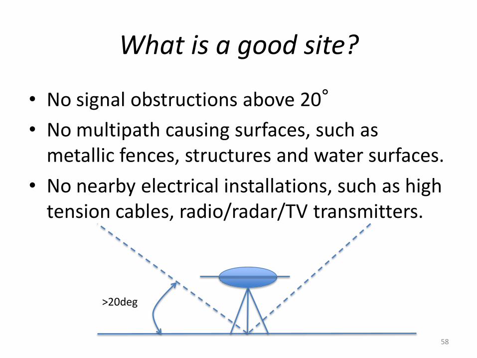
What is a good site?
• No signal obstructions above 20°
• No multipath causing surfaces, such as metallic fences, structures and water surfaces.
• No nearby electrical installations, such as high tension cables, radio/radar/TV transmitters.
>20deg
58

EQUIPMENT LISTS
• Equipment necessary to carry out a GPS survey can be categorized according to whether it is:
– Equipment per site for field work.
– Equipment at a base station or the field office.
59
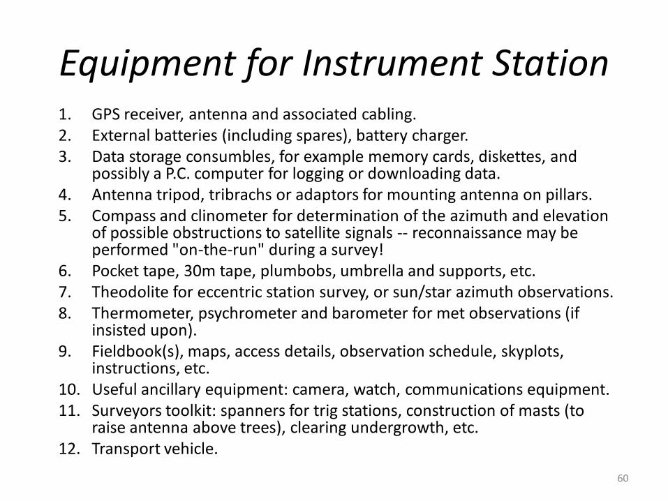
Equipment for Instrument Station1. GPS receiver, antenna and associated cabling. 2. External batteries (including spares), battery charger. 3. Data storage consumbles, for example memory cards, diskettes, and
possibly a P.C. computer for logging or downloading data. 4. Antenna tripod, tribrachs or adaptors for mounting antenna on pillars. 5. Compass and clinometer for determination of the azimuth and elevation
of possible obstructions to satellite signals -- reconnaissance may be performed "on-the-run" during a survey!
6. Pocket tape, 30m tape, plumbobs, umbrella and supports, etc. 7. Theodolite for eccentric station survey, or sun/star azimuth observations. 8. Thermometer, psychrometer and barometer for met observations (if
insisted upon). 9. Fieldbook(s), maps, access details, observation schedule, skyplots,
instructions, etc. 10. Useful ancillary equipment: camera, watch, communications equipment. 11. Surveyors toolkit: spanners for trig stations, construction of masts (to
raise antenna above trees), clearing undergrowth, etc. 12. Transport vehicle.
60
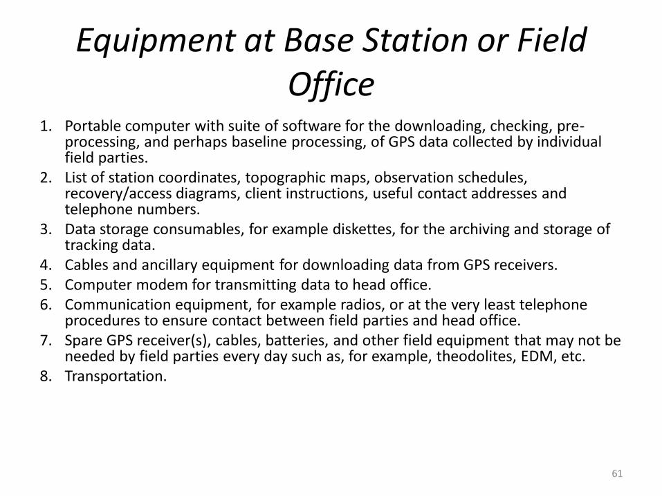
Equipment at Base Station or Field Office
1. Portable computer with suite of software for the downloading, checking, pre-processing, and perhaps baseline processing, of GPS data collected by individual field parties.
2. List of station coordinates, topographic maps, observation schedules, recovery/access diagrams, client instructions, useful contact addresses and telephone numbers.
3. Data storage consumables, for example diskettes, for the archiving and storage of tracking data.
4. Cables and ancillary equipment for downloading data from GPS receivers. 5. Computer modem for transmitting data to head office. 6. Communication equipment, for example radios, or at the very least telephone
procedures to ensure contact between field parties and head office. 7. Spare GPS receiver(s), cables, batteries, and other field equipment that may not be
needed by field parties every day such as, for example, theodolites, EDM, etc. 8. Transportation.
61

PARTY ORGANISATION & LOGISTICS • Each field party generally comprises of one or two members trained to
operate the GPS and ancillary equipment, and well briefed on the observation plan
• The campaign manager, on the other hand, is responsible for carrying out (or at the very least supervising):– The survey planning, the technical as well as the administrative tasks
such as contacting the relevant authorities to gain station access permission; booking accommodation and transport; investigation of facilities such as communications, power supplies (for computers and receivers), etc.
– The pre-mission tasks such as logistical planning; testing and validating equipment; reconnaissance; site preparation; briefing of staff; etc.
– The day-to-day management of the field parties, including preparation of contingency plans in the event of instrument failures, etc.; and implementing changes to the observing schedule.
– The supervision of the field processing of GPS data to check data validity; perform a preliminary network adjustment as the survey progresses; recommend alterations to the schedule in order to reobserve sites, observe new stations, etc.
62
ON-SITE PROCEDURES FOR FIELD-STATIC SURVEYS
63
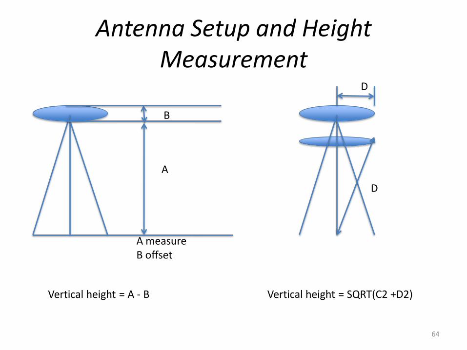
Antenna Setup and Height Measurement
Vertical height = A - B Vertical height = SQRT(C2 +D2)
B
A
A measureB offset
D
D
64

• The antenna normally bears a direction indicator that should be oriented in the same direction at all sites using a compass. The same antenna, receiver and cabling should be maintained together in a "kit".
• Centering of the antennas is important. If centering is poor, the accuracy of the overall survey will suffer hence plumb bobs should be avoided. Tribrachs with built-in optical plummets should be regularly calibrated.
• The antenna assembly should therefore be mounted on a standard survey tribrach with an optical plummet, on a good quality survey tripod.
• Setting up on a pillar is, of course, reasonably effortless and to be preferred.
• If the receiver is to remain on-site for two or more observing sessions, the antenna should be re-positioned each time.
• Care must be taken with antenna height measurement.
Antenna Setup and Height Measurement
65
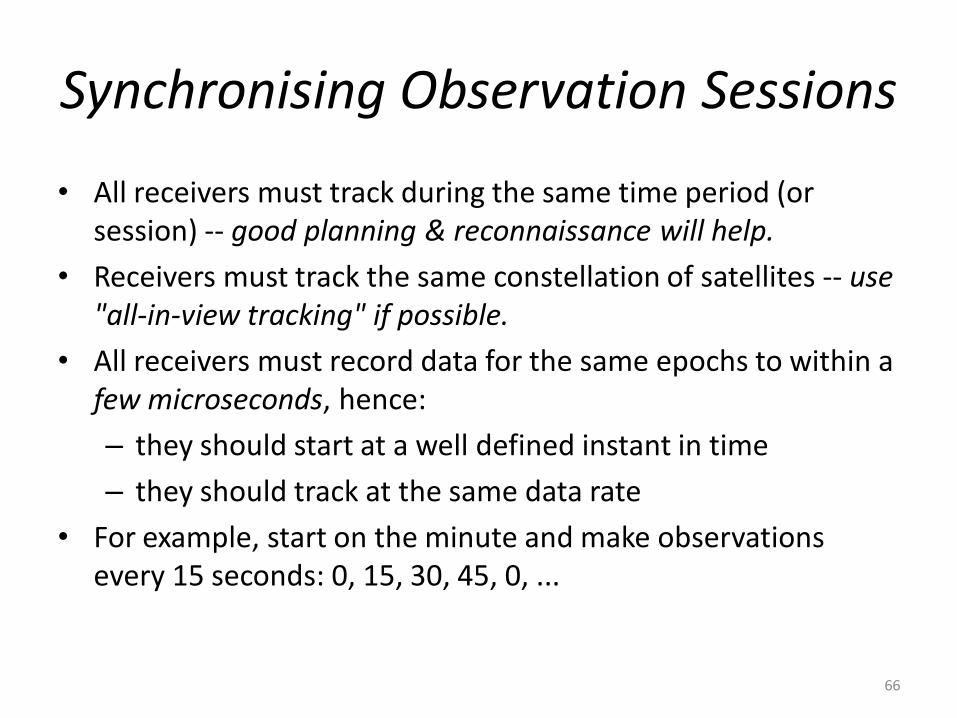
Synchronising Observation Sessions
• All receivers must track during the same time period (or session) -- good planning & reconnaissance will help.
• Receivers must track the same constellation of satellites -- use "all-in-view tracking" if possible.
• All receivers must record data for the same epochs to within a few microseconds, hence:
– they should start at a well defined instant in time
– they should track at the same data rate
• For example, start on the minute and make observations every 15 seconds: 0, 15, 30, 45, 0, ...
66

Field Log SheetsSuch a sheet would typically contain the following
information:– Date and time, field crew details, etc. – Station name and number (including aliases, site codes, etc.). – Session number, or other campaign indicator. – Serial numbers of receiver, antenna, data logger, memory card,
etc. – Start and end time of observations (actual and planned). – Satellites observed during session (actual and planned). – Antenna height (several measurements), and eccentric station
offsets (if used). – Weather (general remarks), and meteorological observations if
requested (such as temperature, pressure and relative humidity). – Receiver operation parameters such as data recording rate, type
of observations being made, elevation mask angle imposed, data format used, etc.
– Any receiver, battery, operator or tracking problems that were noticed.
– Sketch of the site showing all marks, possible obstructions, etc. 67

Field Log Sheets (2)
68
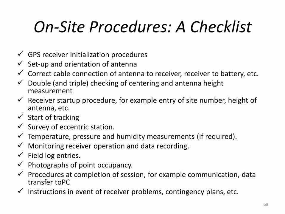
On-Site Procedures: A Checklist
GPS receiver initialization procedures Set-up and orientation of antenna Correct cable connection of antenna to receiver, receiver to battery, etc. Double (and triple) checking of centering and antenna height
measurement Receiver startup procedure, for example entry of site number, height of
antenna, etc. Start of tracking Survey of eccentric station. Temperature, pressure and humidity measurements (if required). Monitoring receiver operation and data recording. Field log entries. Photographs of point occupancy. Procedures at completion of session, for example communication, data
transfer toPC Instructions in event of receiver problems, contingency plans, etc.
69

Receiver Operation Monitoring Checklist:
Battery status (and expected period of operation)
Memory capacity left
Satellites being tracked
Real-time navigation position solution
Satellite health (also useful for post-processing)
Date and time (UTC or local)
Elevation & azimuth of satellites (compare with predictions or skyplot)
"Signal-to-noise" ratios
Antenna connection indicator
Tracking channel status
Amount of data being logged
70
What about collecting meteorological data?
• FORGET IT!!Why?• Commercial software does not accept (yet?)
meteorological data for tropospheric refraction correction.
• Met data cannot be measured to the required precision (particularly that part critical for the wet component of the troposphere).
• Field staff have other more important things to do while data are being collected.
71

FIELD OFFICE PROCEDURES • Data should be processed as soon as possible after the observation
session!
• Typical field office procedures:– Data handling tasks -- transfer of data from receiver to computer.
– Data verification, backup and archiving in field office -- transmit raw data to head office?
– Preliminary computation of baselines in field office.
– Preliminary quality control procedures, such as the inspection of repeated baselines, loop closures, and evaluation of (incomplete) minimally constrained network.
– If appropriate software available, minimally constrained network for entire campaign can be built up one session at a time.
– Command and control of survey parties -- develop contingency plans for repeated observation sessions.
– Oversee calibration and testing of field equipment.
– Preparation of campaign report, and maintain ensure reporting to head office and/or the client.
72

A few more tips:
• Download data ASAP. • Follow procedures in the Operator's Manual. (RTMs)• Most GPS receivers have many hours of internal memory, so daily
download is a reasonable routine. • Delete files from receiver memory when data download procedure has
been verified. • Download to PC hard disk, then to external disks, then make backup
copies. • Store backup disks separately. • Label storage devices. • Be ruthlessly systematic with storage and labelling files. • Cross-reference booking sheets to data files. • Verify data download, for example check number and size of files, and
process as quickly as possible.
73

Guarding against the "ultimate fieldwork sins"
• Power loss is the most common cause of GPS equipment failure. – always have back-up power supplies!
• Cable problems are the next most common sources of failure. – keep them in good condition!
• Incorrect operation of receiver.– field staff must be trained!
• Antenna height reading error is probably the most common field error affecting GPS survey quality.– know the antenna phase centre, check and recheck height reading!
• Are you on the correct station?– good reconnaissance helps, get evidence of occupation!
• Data collection must be coordinated, only common data from a minimum of two sites can be processed.– good teamwork, well designed observation schedule and well trained
field staff!• Loss of data after survey session ends.• use ruthlessly systematic data management procedures!
74

REOCCUPATION GPS SURVEYING TECHNIQUES
• Centimeteepositioning accuracy with two occupations per site, each for a short static observation period (few minutes) ...
• Also known variously as pseudo-kinematic and pseudo-static.
• This technique exploits changes in satellite geometry across conventional observation sessions.
• The roving receiver must revisit the same point one or more hours later
• Two separate sets of ambiguities must be estimated, one for the first session, the other for the second session.
75

“Reoccupation" surveying technique
• somewhere between conventional static and "kinematic" techniques in terms of productivity.
• It is faster than conventional static, but it is not as accurate, if only an ambiguity-free solution is usually obtained. An ambiguity-fixed solution, if obtained, is more accurate.
• It is an alternative to the "rapid static" technique, no faster but also not as accurate unless ambiguities are resolved (in which case it is identical to the "rapid static" technique).
• It is more flexible than the "stop & go" or "kinematic" techniques as it does not require that satellites be tracked while the receiver is being moved from site to site.
76
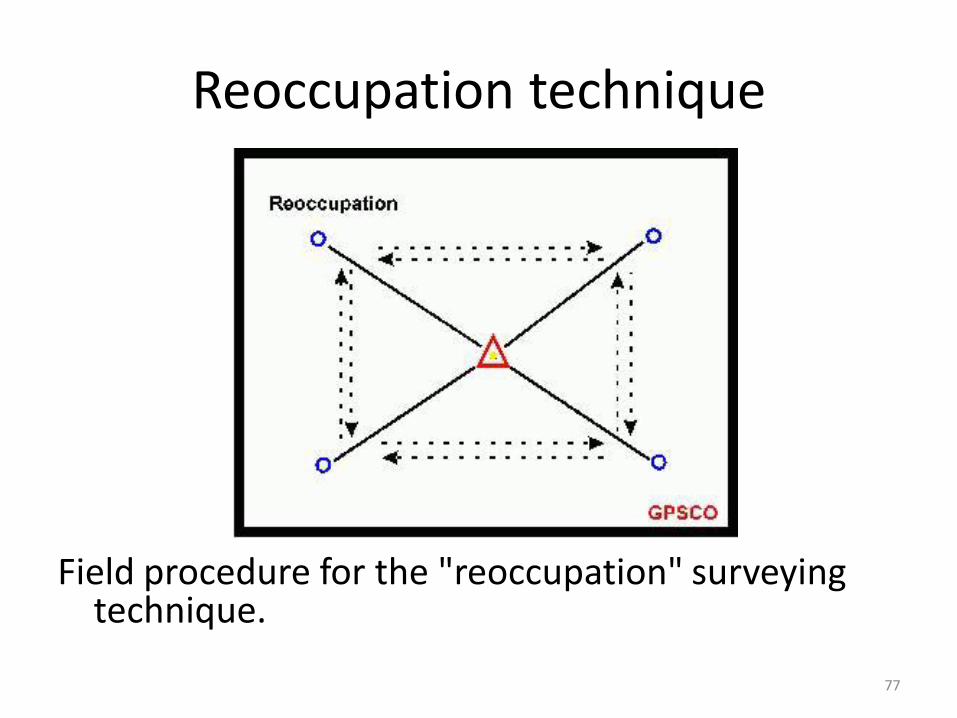
Reoccupation technique
Field procedure for the "reoccupation" surveying technique.
77

"STOP & GO" GPS SURVEYING TECHNIQUES
• Centimetre accuracy positioning during very short static observation periods (<1minute) ... receiver moves carefully from point to point ...
• This is a true kinematic technique because the receiver continues to track satellites while it is in motion.
• Coordinates of the receiver are only of interest when it is stationary (the "stop" part), but the receiver continues to function while it is being moved (the "go" part) from one stationary setup to the next.
78

Three stages to the "stop & go" operation
1. The initial ambiguity resolution: This is carried out (generally in static mode) before the "stop & go" survey commences.
2. The receiver in motion:– Once the ambiguities have been determined the survey can begin.– The roving receiver is moved from site to site, collecting just a
few minutes of phase data. – It is very important that the antenna continues to track the
satellites.– This can most easily be done by bringing the receiver back to the
last surveyed point, and redetermining the ambiguities by the "known baseline" method.
3. The stationary receiver:1. The "carrier-range" data is then processed in the double-
differenced mode to determine the coordinates of the roving receiver relative to the static reference receiver.
2. The trajectory of the antenna is not of interest, only the stationary points which are visited by the receiver.
79

Procedure for determining ambiguities• A conventional static (or "rapid static") GPS survey
determines the baseline from a fixed receiver to the first of the uncoordinated sites occupied by the second "roving" receiver.
• Setup both receivers over a known baseline, possibly surveyed previously by GPS.
• Employ a procedure known as "antenna swap". 1. Two tripods are setup a few metres apart, each
with an antenna on them (the exact baseline length need not be known).
2. Data is collected by each receiver for a few minutes (tracking the same satellites). The antennas are then carefully lifted from the tripods and swapped, that is, the receiver 1 antenna is placed where the receiver 2 antenna had been, and visa versa
3. After a few more minutes the antennas are swapped again
80

Field procedure for the "stop & go" technique
The technique is well suited when many points close together have to be surveyed, and the terrain poses no significant problems in terms of signal disruption
An additional requirement is that the stationary reference receiver must continue to track all the satellites being tracked by the roving receiver.
81
KINEMATIC GPS SURVEYING TECHNIQUES
• Centimeter positioning accuracy of moving antenna ..
• Generalization of the "stop & go" technique
• Determines the position of the antenna only while it is in motion
• Ambiguities must be resolved before starting the survey, and the ambiguities must be reinitialised during the survey when a cycle slip occurs.
• Today the "kinematic" GPS surveying technique is undergoing tremendous improvement and "on-the-fly" ambiguity resolution is a routine procedure
82

Trends in "kinematic" surveying • Blurring distinction between "kinematic GPS surveying" and "kinematic GPS
navigation". – The former is carrier phase based (actually "carrier-range" data), whereas
the latter has usually been taken to refer to pseudo-range based positioning.
– However, nowadays more navigation instruments are using "carrier phase smoothed pseudo-ranges"
• Combination of both phase and pseudo-range data within the positioning algorithm itself, precise C/A code ranges as well as P code pseudo-ranges.
• Increasing sophistication of the algorithms, for example, incorporating Kalman filters.
• Techniques based on single frequency data, as well as those top-of-the-line procedures requiring dual-frequency data.
• "On-the-fly" ambiguity resolution techniques will probably all other "kinematic" techniques (and possibly the "rapid static" and "reoccupation" techniques as well).
• Real-time operation ("real-time kinematic" -- RTK) is increasingly popular as it offers considerable advantages in that the results are available immediately, in the field, but it is still a challenge and operates under a number of significant constraints.
83
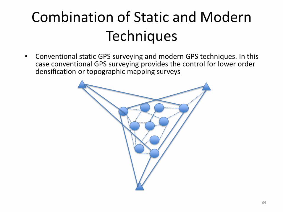
Combination of Static and Modern Techniques
• Conventional static GPS surveying and modern GPS techniques. In this case conventional GPS surveying provides the control for lower order densification or topographic mapping surveys
84

ISSUES RELATING TO MODERN GPS SURVEYING
CONVENTIONAL (STATIC) GPS SURVEYING:
Advantages Highest accuracy Robust technique
Ambiguity resolution not critical
Minor impact of orbit error and multipath
Undemanding of hardware and software
DisadvantagesLong observation sessions
Inappropriate for engineering and cadastral applications
85

ISSUES RELATING TO MODERN GPS SURVEYING
MODERN GPS SURVEYING (Rapid Static and Kinematic)
Advantages1. Higher accuracy than
pseudo-range solutions 2. Appropriate for many
survey applications 3. High productivity 4. Similar procedures to
modern terrestrial surveying
Disadvantages1. Special hardware and
software 2. Susceptible to orbit,
atmospheric multi-path disturbances
3. Higher capital costs 4. Ambiguity-fixed or
continuous lock required
86
Two negative characteristics of these modern GPS techniques
1. They are susceptible to multipath disturbance to an extent
– Multipath during the ambiguity resolution period is especially dangerous, as wrong ambiguities may result.
2. The results from short observation sessions are more sensitive to bad satellite geometry (large GDOP) than the conventional static technique.
87

Applications and Productivity: A comparison
Observation 1010-1111 45 min
Move from 1010 to 2222(setup) 13 min
Observation 1111-2222 45 min
Move from 1111 to 3333(setup) 16 min
Observation 2222 to 3333 45 min
Move from 2222 to 4444(setup) 14 min
Observation 3333-4444 45 min
Move from 3333 to 1010(setup) 16 min
Observation 1010-4444 45 min
284 min
Total time: 4 h 44 minutes
Observation 1010,1111,1011 45 min
Move time and setup 23 min
Observation 1111,2222,3333 45 min
Move time and setup 16 min
Observation 4444,3333,1011 45 min
Move time and setup 22 min
Observation 1010,4444,2222 45 min
241 min
Total time: 4 h 01 minutes
88

Applications and Productivity: A comparison
Initialize survey (antenna swap @ station 1010: 4 satelites)
13 min
Move to 1111(setup) 11 min
Observation 1010-1111 1 min
Move to 2222(setup) 12 min
Observation 1010-2222 1 min
Move to 3333(setup) 11 min
Observation 1010-3333 1 min
Move to 4444(setup) 9 min
Observation 1010-4444 1 min
Move to 1111(setup) 18 min
Reobserve 1111(as a check) 1 min
79 min
This method takes less time than the first configuration:79 minutes -19 minutes (last reobservation of station 1111) =
68 minutes
89

Summary
• Certain specifications must be followed to achieve certain standard in any GPS surveying work
• Good documentation (field notes, field plans) is a key to a successful GPS project
• It is important to determine the requirement of the client/application to design the survey accordingly.
90

References
• US Army Corps of Engineers (USACE) - EM 1110-1-1004 Geodetic and Control Surveys
• Weston,Neil, Schwieger, Volker (FIG PUBLICATION NO. 49Cost Effective GNSS Positioning TechniquesFIG Commission 5 Publication
• Rizos, Chris, Principles and Practice
• of GPS Surveying. (http://www.gmat.unsw.edu.au/snap/gps/gps_survey/principles_gps.htm)
91