application-oriented operating systems - ufsc
TRANSCRIPT

Application-Oriented Operating Systems
Antônio Augusto Medeiros Fröhlich
June 2001


To my son Alek.

Acknowledgements
This dissertation is the summit of a research project that was supported by several peopleand institutions, to which I am very grateful. At first, I am very grateful to my wifeLuciane for being my “best friend” and giving me emotional peace to enjoy this wonderfuljourney.
I would like to thank my supervisors Prof. Jähnichen and Prof. Schröder-Preikschat forthe invaluable scientific assistance they provided. Prof. Jähnichen looked after a prolificacademic environment and an incomparable research infrastructure, allowing this researchto surpass its original goals. Prof. Schröder-Preikschat dedicated uncountable hours todiscuss with me the most diverse topics of operating system construction. His exceptionalperspective of the subject deeply influenced this dissertation, motivating me to move awayfrom the mainstream and break barriers that formerly seemed insurmountable.
Many thanks to those who helped this doctoral project to come true. The FederalUniversity of Santa Catarina for giving me leave to join GMD-FIRST, in particular thecolleagues that took over my tuition duties and my representative Prof. Leite. The CAPESagency for the financial and organizational support. The GMD-FIRST institute, in par-ticular Prof. Behr and former associate researcher Dr. Jörg Cordsen who “opened up thedoor”.
I also would like to thank the “Fluchtsofa” fellows—some of the most brilliant mindsI ever had the pleasure to bother with my endless questions—for teaching me the im-portance of the “Reinheitsgebot”. In particular Friedrich Schön, for the comprehensiveinsight of software engineering, and my students Gilles P. Tientcheu and Sascha Römkefor the dedicated work on EPOS.
Loving thanks to my parents Arno and Nadir for shortening the distance betweenGermany and Brazil with their daily e-mails and sporadic visits.
Berlin, June 2001.
v


Abstract
The majority of processors produced nowadays are targeted atdedicated computing sys-temsthat execute either a single application or a small set of previously known applica-tions. In contrast to generic computing systems, these dedicated systems have very spe-cific run-time support requirements, which are not properly fulfilled by general-purposeoperating systems. The impossibility to anticipate which applications will be executedresults in generic operating systems being forced to provide an extensive set of servicestargeted at making all resources available to all applications. The standardization of suchgeneric system services locked general-purpose operating system inside a hard shell thatprevents innovations from reaching applications. With regard to dedicated computing,these generic operating system provide uncountable services that are not used by individ-ual applications, and yet fail to fulfill application demands.
This dissertation proposes a novel strategy to systematically construct application-oriented operating systems as arrangements of adaptable software components. Instead ofstandard compliance and hardware properties, the features offered by such a system em-anate directly from application requirements, thus enabling it to be customized accordingto the needs of particular applications. Such application-tailored system instances are pro-duced by selecting, configuring, and composing proper components. Even if applicationsrefrain from the new application-oriented services in benefit of standard interfaces, mostdedicated applications require such a small subset of those interfaces that mapping themto new system services—instead of porting their traditional implementations—is usuallypossible.
TheApplication-Oriented System Designmultiparadigm design method proposed inthis dissertation guides domain decomposition towardsfamilies of scenario-independentsystem abstractionsthat can be reused to build a variety of run-time support systems.Environmental dependencies observed during domain decomposition are separately mod-eled asscenario aspects, which can be transparently applied to system abstractions withthe aid ofscenario adapters. The assembling of suchsoftware componentsto producea functioning system is assisted bycomponent frameworks, which capture elements ofreusable software architecture identified in the course of domain engineering. Usabilityis improved byinflated interfaces, which export whole families of abstractions to users asif they were single macrocomponents, passing the responsibility of selecting appropriatefamily members to the system.
vii

� Abstract
The concepts and techniques introduced by application-oriented system design wereverified during the development of EPOS (Embedded Parallel Operating System), anapplication-oriented operating system for the domain of high-performance dedicatedcomputing. The prototype of EPOS implemented for the SNOW cluster of workstationsconsists of a repository of software components that encapsulate system abstractionsand scenario aspects, a statically metaprogrammed component framework, and a set oftools that is able to automatically select and configure components in order to generateapplication-oriented system instances.
Keywords: application-oriented operating system, parallel and embedded systems,software components, domain engineering, object-oriented design, family-based design,generative programming, aspect-oriented programming, static metaprogramming.
viii

Zusammenfassung
Die Mehrzahl der heutzutage produzierten Prozessoren, wird inSpezialsystemeneinge-setzt, die einer einzelnen oder von einer kleinen Zahl vorher bekannter Anwendungengewidmet sind. Der Betrieb solcher Spezialsysteme unterliegt besonderen Anforderun-gen, die Allzweckbetriebssysteme, wie sie auf Arbeitsplatzrechnern zum Einsatz kom-men, in der Regel nicht erfüllen können. Da es vorab nicht möglich ist anzugeben,welche Anwendungen ausgeführt werden sollen, bieten Allzweckbetriebssysteme poten-tiellen Anwendungen vorsichtshalber eine sehr große Menge von Diensten an. Die Stan-dardisierung solcher allgemeinen Dienste schließt ein Allzweckbetriebssystem in starreSchranken ein und erschwert die Nutzbarmachung innovativer Konzepte für die Anwen-dung. Das Problem von Allzweckbetriebssystemen für Spezialrechensysteme ist, dasseinerseits unzählige Dienste angeboten werden, die die Anwendungen gar nicht benöti-gen, andererseits aber spezielle Anforderungen nicht erfüllt werden.
In dieser Arbeit wird ein neuer Ansatz dargelegt, um aus anpassungsfähigen Software-bausteinen systematisch anwendungsorientierte Betriebssysteme zu konstruieren. Anstattdie Eigenschaften eines Systems aus Standardfunktionen und Hardwareeigenschaftenabzuleiten, bestimmen die Anforderungen der Anwendungen die konkrete Systemausprä-gung. Dies vereinfacht die Konstruktion angepasster Systeme. Solche anwendungsspezi-fischen Systeme werden durch Auswahl, Konfiguration und Integration geeigneter Kom-ponenten gebildet. Dieser Ansatz ist sinnvoll selbst dann, wenn Anwendungen neueSpezialisierungen zunächst nicht nutzen und stattdessen ausschließlich auf Standardfunk-tionen zurückgreifen. Die Mehrzahl der Spezialsysteme benutzt nur eine Teilmenge derStandardfunktionen, so dass es vergleichsweise einfach ist, diese Teilmenge auf neue Sys-temdienste abzubilden, ohne dabei alle Standardfunktionen zu portieren.
Die in dieser Arbeit diskutierteanwendungsorientierte Entwurfsmethodikbasiertauf der Zerlegung eines Anwendungsgebietes in eine Menge vonFamilien szenario-unabhängiger Systemabstraktionen, die je nach Bedarf zur Konstruktion einesangepassten Laufzeitsystems wiederverwendet werden. Umgebungsabhängigkeiten, diewährend der Zerlegung auftreten, werden getrennt als sogenannteSzenario-Aspektemod-elliert und wirken eigenständig in Form vonSzenario-Adapternauf die Systemabstrak-tionen ein. Die Spezialisierung und Integration solcherSoftwarekomponentenzu einemfunktionsfähigen Gesamtsystem wird durchKomponentengerüsteergänzt, die die im Ver-lauf der Zerlegung eines Anwendungsgebietes identifizierten, wiederverwendbaren El-
ix

� Zusammenfassung
emente der Software-Architektur erfassen. Die Anwendbarkeit der Komponenten wirdweiterhin durch die Bereitstellung einerumfassenden Schnittstelleverbessert. Jede dieserumfassenden Schnittstellen exportiert eine ganze Familie von Abstraktionen und wirktdadurch als eine Art Makrokomponente. Daraus folgt, dass die Auswahl geeigneter Fam-ilienmitglieder dem System überlassen wird.
Die Konzepte und Techniken, die durch dieanwendungsorientierte Entwurfsmethodikeingeführt wurden, wurden bei der Entwicklung von EPOS(Embedded Parallel OperatingSystem), einem anwendungsorientierten Betriebssystem für das Gebiet des spezialisiertenHochleistungsrechnens, überprüft. Der Prototyp von EPOSwurde auf einem Cluster vonArbeitsplatzrechnern implementiert und besteht aus einer Sammlung von Softwarekom-ponenten, aus einem statisch meta-programmierten Komponentengerüst und schließlicheinem Satz von Werkzeugen zur automatischen Auswahl, Konfiguration und Erzeugunganwendungsorientierter Systeminstanzen.
Schlagwörter: anwendungsorientierte Betriebssysteme, parallele und eingebettete Sys-teme, Softwarekomponenten, Domain Engineering, objektorientierter Entwurf, fami-lienbasierter Entwurf, generative Programmierung, Aspekt-orientierte Programmierung,statische Metaprogrammierung.
x

Contents
List of Figures xv
List of Tables xix
1 Introduction 1
1.1 Prologue . . . . . . . . . . . . . . . . . . . . . . . . . . . . . . . . . . . 1
1.2 Motivation and Goals . . . . . . . . . . . . . . . . . . . . . . . . . . . . 4
1.3 Contributions . . . . . . . . . . . . . . . . . . . . . . . . . . . . . . . . 5
1.4 Overview . . . . . . . . . . . . . . . . . . . . . . . . . . . . . . . . . . 7
2 Customizable Operating Systems 9
2.1 Configurability . . . . . . . . . . . . . . . . . . . . . . . . . . . . . . . 9
2.1.1 Static Configurability . . . . . . . . . . . . . . . . . . . . . . . . 11
2.1.2 Dynamic Configurability . . . . . . . . . . . . . . . . . . . . . . 13
2.2 Designing for Customizability . . . . . . . . . . . . . . . . . . . . . . . 15
2.2.1 Family-Based Design . . . . . . . . . . . . . . . . . . . . . . . . 16
2.2.1.1 Incremental System Design . . . . . . . . . . . . . . . 17
2.2.2 Object-Oriented Design . . . . . . . . . . . . . . . . . . . . . . 19
2.2.3 Collaboration-Based Design . . . . . . . . . . . . . . . . . . . . 22
2.2.4 Subject-Oriented Programming . . . . . . . . . . . . . . . . . . 23
2.2.5 Aspect-Oriented Programming . . . . . . . . . . . . . . . . . . . 24
2.2.6 Multiparadigm Design . . . . . . . . . . . . . . . . . . . . . . . 25
2.3 Implementing Customizable Designs . . . . . . . . . . . . . . . . . . . . 26
2.3.1 Software Components . . . . . . . . . . . . . . . . . . . . . . . 26
2.3.2 Component Granularity . . . . . . . . . . . . . . . . . . . . . . 28
2.3.3 Component Composition . . . . . . . . . . . . . . . . . . . . . . 29
xi

� Contents
2.3.3.1 Interfaces . . . . . . . . . . . . . . . . . . . . . . . . 30
2.3.3.2 Contracts . . . . . . . . . . . . . . . . . . . . . . . . . 30
2.3.3.3 Design Patterns . . . . . . . . . . . . . . . . . . . . . 31
2.3.3.4 Frameworks . . . . . . . . . . . . . . . . . . . . . . . 32
2.3.3.5 Collaborations . . . . . . . . . . . . . . . . . . . . . . 33
2.3.3.6 Static Metaprogramming . . . . . . . . . . . . . . . . 34
2.3.4 Component Configuration . . . . . . . . . . . . . . . . . . . . . 36
2.4 Summary . . . . . . . . . . . . . . . . . . . . . . . . . . . . . . . . . . 38
3 Application-Oriented System Design 41
3.1 The Case for Application-Orientation . . . . . . . . . . . . . . . . . . . 41
3.2 Application-Oriented Operating Systems . . . . . . . . . . . . . . . . . . 44
3.3 Domain Analysis and Decomposition . . . . . . . . . . . . . . . . . . . 45
3.3.1 Application-Oriented Domain Decomposition . . . . . . . . . . . 45
3.3.2 An Example of Domain Decomposition . . . . . . . . . . . . . . 48
3.4 Families of Scenario-Independent Abstractions . . . . . . . . . . . . . . 52
3.5 Scenario Aspects . . . . . . . . . . . . . . . . . . . . . . . . . . . . . . 56
3.6 Inflated Interfaces . . . . . . . . . . . . . . . . . . . . . . . . . . . . . . 58
3.7 Reusable System Architectures . . . . . . . . . . . . . . . . . . . . . . . 64
3.8 Implementation Considerations . . . . . . . . . . . . . . . . . . . . . . . 68
3.8.1 Abstractions . . . . . . . . . . . . . . . . . . . . . . . . . . . . 68
3.8.2 Inflated Interfaces . . . . . . . . . . . . . . . . . . . . . . . . . . 78
3.8.3 Scenario Aspects . . . . . . . . . . . . . . . . . . . . . . . . . . 80
3.9 Summary . . . . . . . . . . . . . . . . . . . . . . . . . . . . . . . . . . 86
4 The EPOS System 89
4.1 A Bit of History . . . . . . . . . . . . . . . . . . . . . . . . . . . . . . . 89
4.2 Fundamentals . . . . . . . . . . . . . . . . . . . . . . . . . . . . . . . . 90
4.3 System Abstractions . . . . . . . . . . . . . . . . . . . . . . . . . . . . 91
4.3.1 Memory Management . . . . . . . . . . . . . . . . . . . . . . . 93
4.3.1.1 Memory Segments . . . . . . . . . . . . . . . . . . . . 94
4.3.1.2 Address Spaces . . . . . . . . . . . . . . . . . . . . . 95
xii
Contents�
4.3.2 Process Management . . . . . . . . . . . . . . . . . . . . . . . . 96
4.3.2.1 Tasks . . . . . . . . . . . . . . . . . . . . . . . . . . . 97
4.3.2.2 Threads . . . . . . . . . . . . . . . . . . . . . . . . . 97
4.3.2.3 Processor Schedulers . . . . . . . . . . . . . . . . . . 99
4.3.3 Process Coordination . . . . . . . . . . . . . . . . . . . . . . . . 102
4.3.3.1 Synchronizers . . . . . . . . . . . . . . . . . . . . . . 103
4.3.4 Inter-Process Communication . . . . . . . . . . . . . . . . . . . 104
4.3.4.1 Communicators . . . . . . . . . . . . . . . . . . . . . 105
4.3.4.2 Channels . . . . . . . . . . . . . . . . . . . . . . . . . 106
4.3.4.3 Networks . . . . . . . . . . . . . . . . . . . . . . . . . 108
4.3.4.4 Message Envelopes . . . . . . . . . . . . . . . . . . . 109
4.3.5 Time Management . . . . . . . . . . . . . . . . . . . . . . . . . 110
4.3.6 I/O Management . . . . . . . . . . . . . . . . . . . . . . . . . . 111
4.3.6.1 Buses . . . . . . . . . . . . . . . . . . . . . . . . . . . 111
4.3.6.2 Devices . . . . . . . . . . . . . . . . . . . . . . . . . 112
4.3.6.3 Interrupt Handlers . . . . . . . . . . . . . . . . . . . . 113
4.3.7 External Abstractions . . . . . . . . . . . . . . . . . . . . . . . . 114
4.3.8 Summary of EPOS Abstractions . . . . . . . . . . . . . . . . . . 115
4.4 Scenario Aspects . . . . . . . . . . . . . . . . . . . . . . . . . . . . . . 117
4.4.1 Identification . . . . . . . . . . . . . . . . . . . . . . . . . . . . 117
4.4.2 Sharing . . . . . . . . . . . . . . . . . . . . . . . . . . . . . . . 119
4.4.3 Allocation . . . . . . . . . . . . . . . . . . . . . . . . . . . . . . 120
4.4.4 Protection . . . . . . . . . . . . . . . . . . . . . . . . . . . . . . 121
4.4.5 Timing . . . . . . . . . . . . . . . . . . . . . . . . . . . . . . . 122
4.4.6 Atomicity . . . . . . . . . . . . . . . . . . . . . . . . . . . . . . 123
4.4.7 Remote Invocation . . . . . . . . . . . . . . . . . . . . . . . . . 125
4.4.8 Debugging and Profiling . . . . . . . . . . . . . . . . . . . . . . 127
4.4.9 Summary of EPOS Scenario Aspects . . . . . . . . . . . . . . . 128
4.5 System Architectures . . . . . . . . . . . . . . . . . . . . . . . . . . . . 129
4.5.1 Component Framework . . . . . . . . . . . . . . . . . . . . . . . 129
4.5.1.1 Framework Metaprogram . . . . . . . . . . . . . . . . 130
xiii

� Contents
4.5.1.2 Composition Rules . . . . . . . . . . . . . . . . . . . 134
4.5.2 Portability . . . . . . . . . . . . . . . . . . . . . . . . . . . . . . 136
4.5.2.1 The Setup Utility . . . . . . . . . . . . . . . . . . . . 137
4.5.2.2 Hardware Mediators . . . . . . . . . . . . . . . . . . . 137
4.5.3 Initialization . . . . . . . . . . . . . . . . . . . . . . . . . . . . 139
4.5.3.1 The Init Utility . . . . . . . . . . . . . . . . . . . . . . 139
4.5.3.2 System Organization . . . . . . . . . . . . . . . . . . 141
4.6 Automatic Configuration . . . . . . . . . . . . . . . . . . . . . . . . . . 142
4.7 Summary . . . . . . . . . . . . . . . . . . . . . . . . . . . . . . . . . . 146
5 EPOS Implementation for the SNOW Cluster 149
5.1 Why a Cluster of Workstations? . . . . . . . . . . . . . . . . . . . . . . 149
5.2 The SNOW Cluster . . . . . . . . . . . . . . . . . . . . . . . . . . . . . 151
5.2.1 Processing Nodes . . . . . . . . . . . . . . . . . . . . . . . . . . 151
5.2.2 Interconnects . . . . . . . . . . . . . . . . . . . . . . . . . . . . 153
5.3 EPOS Implementation . . . . . . . . . . . . . . . . . . . . . . . . . . . 154
5.3.1 The Myrinet Network Abstraction . . . . . . . . . . . . . . . . . 156
5.3.2 Utilities . . . . . . . . . . . . . . . . . . . . . . . . . . . . . . . 161
5.3.3 Tools . . . . . . . . . . . . . . . . . . . . . . . . . . . . . . . . 162
5.4 Summary . . . . . . . . . . . . . . . . . . . . . . . . . . . . . . . . . . 166
6 Discussion 169
6.1 AOSD in the Realm of Software Engineering . . . . . . . . . . . . . . . 169
6.1.1 Comparison with other Methodologies . . . . . . . . . . . . . . . 172
6.1.2 Support for other Kinds of Design . . . . . . . . . . . . . . . . . 177
6.2 EPOS in the Realm of Operating Systems . . . . . . . . . . . . . . . . . 178
6.2.1 Comparison with other Systems . . . . . . . . . . . . . . . . . . 181
6.3 Perspectives . . . . . . . . . . . . . . . . . . . . . . . . . . . . . . . . . 183
Bibliography 187
xiv

List of Figures
2.1 Stages in which an operating system can be configured. . . . . . . . . . . 10
2.2 A family of scheduling algorithms modeled according to family-baseddesign (a) and incremental system design (b). . . . . . . . . . . . . . . . 18
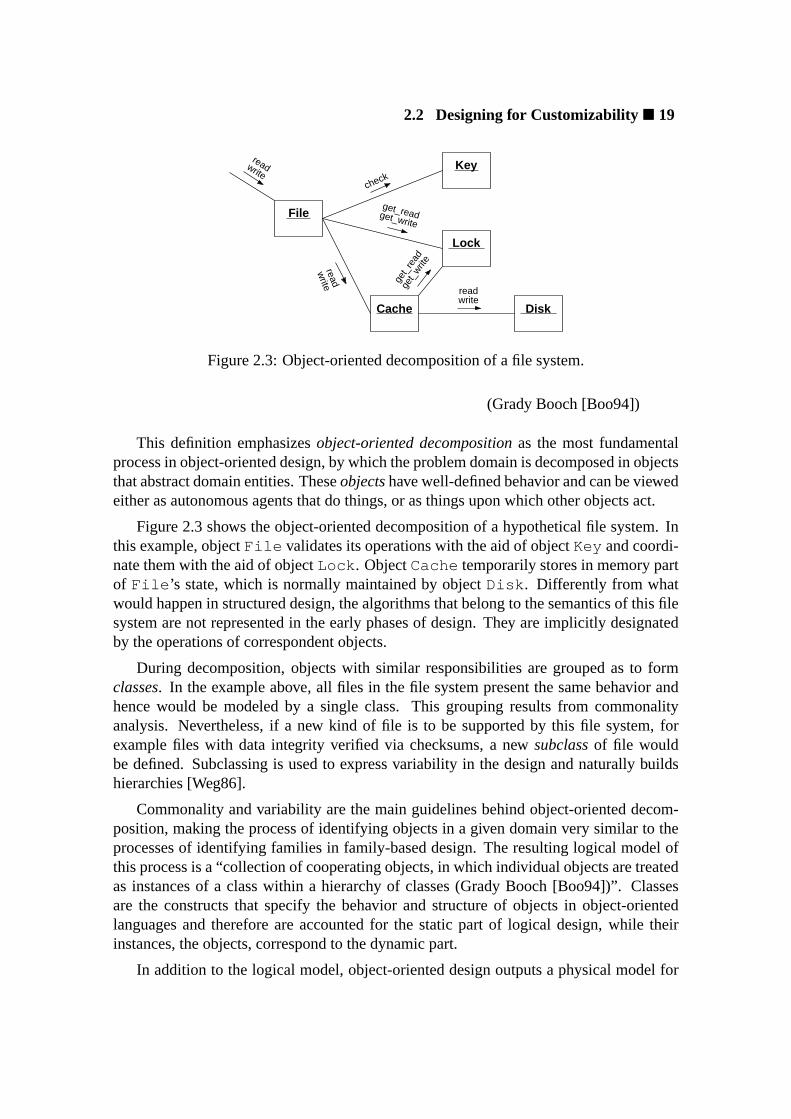
2.3 Object-oriented decomposition of a file system. . . . . . . . . . . . . . . 20
2.4 The models of object-oriented design. . . . . . . . . . . . . . . . . . . . 20
2.5 A collaboration diagram. . . . . . . . . . . . . . . . . . . . . . . . . . . 22
2.6 Subject-oriented composition. . . . . . . . . . . . . . . . . . . . . . . . 23
2.7 Aspect-oriented composition. . . . . . . . . . . . . . . . . . . . . . . . . 24
2.8 Component characteristics versus granularity. . . . . . . . . . . . . . . . 29
2.9 The ADAPTER design pattern. . . . . . . . . . . . . . . . . . . . . . . . 32
2.10 The BRIDGE design pattern. . . . . . . . . . . . . . . . . . . . . . . . . 32
2.11 A component framework. . . . . . . . . . . . . . . . . . . . . . . . . . . 33
2.12 A statically metaprogrammed factorial calculator. . . . . . . . . . . . . . 35
2.13 A statically metaprogrammed profiler that measures the lifetime of objects. 35
2.14 A simple generic resource allocator. . . . . . . . . . . . . . . . . . . . . 37
3.1 An overview of application-oriented domain decomposition. . . . . . . . 48
3.2 Families of abstractions and scenario aspects in the domain of high-performance communication. . . . . . . . . . . . . . . . . . . . . . . . . 49
3.3 A family of networks in the domain of high-performance communication. 50
3.4 A family of communication strategies in the domain of high-performancecommunication. . . . . . . . . . . . . . . . . . . . . . . . . . . . . . . . 50
3.5 A family of communication end-points in the domain of high-performance communication. . . . . . . . . . . . . . . . . . . . . . . . . 51
3.6 The interface of a member of a family of thread abstractions. . . . . . . . 53
3.7 Notation to represent a family of abstractions. . . . . . . . . . . . . . . . 55
xv

� List of Figures
3.8 Inter-family dependencies. . . . . . . . . . . . . . . . . . . . . . . . . . 56
3.9 The general structure of a scenario adapter. . . . . . . . . . . . . . . . . 57
3.10 The representation of a structural scenario aspect. . . . . . . . . . . . . . 57
3.11 The representation of a behavioral scenario aspect. . . . . . . . . . . . . 58
3.12 Partial (a) and selective (b) realization relationships. . . . . . . . . . . . . 59
3.13 Categories of families of abstractions with regard to their inflated interfaces. 60
3.14 The inflated interface of a uniform family of CPU scheduling policies. . . 61
3.15 The inflated interface of an incremental family of thread abstractions. . . 62
3.16 The inflated interface of a dissociated family of file abstractions. . . . . . 63
3.17 The inflated interface of a dissociated family of I/O buses. . . . . . . . . 64
3.18 An application-oriented component framework. . . . . . . . . . . . . . . 65
3.19 A component framework for the domain of high-performance communi-cation. . . . . . . . . . . . . . . . . . . . . . . . . . . . . . . . . . . . . 66
3.20 An overview of application-oriented system design. . . . . . . . . . . . . 67
3.21 An abstraction interface as a C++ pure abstract class declaration. . . . . . 70
3.22 An abstraction interface as a C++ class declaration with a protected de-fault constructor. . . . . . . . . . . . . . . . . . . . . . . . . . . . . . . 71
3.23 An example of uniform family of abstractions implemented in C++. . . . 72
3.24 An example of incremental family of abstractions implemented in C++. . 73
3.25 An example of dissociated family of abstractions implemented in C++. . 74
3.26 An example of combined family of abstractions implemented in C++. . . 75
3.27 A polymorphic family of synchronization abstractions implemented in C++. 77
3.28 An example of inflated interface implemented in C++. . . . . . . . . . . 79
3.29 A C++ example of scenario aspect. . . . . . . . . . . . . . . . . . . . . 81
3.30 Traits of abstractions with regard to scenario aspects. . . . . . . . . . . . 82
3.31 Tiemann’s proposal to wrap member functions in C++. . . . . . . . . . . 83
3.32 Stroustrup’s proposal to wrap member functions in C++. . . . . . . . . . 84
3.33 An alternative to wrap member functions in C++. . . . . . . . . . . . . . 85
4.1 Groups of families of abstraction in EPOS. . . . . . . . . . . . . . . . . . 92
4.2 Families of abstractions concerning memory management in EPOS. . . . 93
4.3 EPOSfamily of memory segments. . . . . . . . . . . . . . . . . . . . . . 94
xvi

List of Figures �
4.4 EPOSfamily of address spaces. . . . . . . . . . . . . . . . . . . . . . . . 95
4.5 Families of abstractions concerning process management in EPOS. . . . . 96
4.6 EPOSfamily of tasks. . . . . . . . . . . . . . . . . . . . . . . . . . . . . 97
4.7 EPOSfamily of threads. . . . . . . . . . . . . . . . . . . . . . . . . . . . 98
4.8 EPOSfamily of processor scheduling policies. . . . . . . . . . . . . . . . 99
4.9 Families of abstractions concerning process coordination in EPOS. . . . . 102
4.10 EPOSfamily of synchronizers. . . . . . . . . . . . . . . . . . . . . . . . 103
4.11 Families of abstractions concerning inter-process communication in EPOS. 104
4.12 EPOSfamily of communicators. . . . . . . . . . . . . . . . . . . . . . . 105
4.13 EPOSfamily of communication channels. . . . . . . . . . . . . . . . . . 107
4.14 The effect of configurable featuresbuffering andgrouping on com-munication channels. . . . . . . . . . . . . . . . . . . . . . . . . . . . . 108
4.15 EPOSfamily of networks. . . . . . . . . . . . . . . . . . . . . . . . . . . 109
4.16 EPOSfamily of message envelopes. . . . . . . . . . . . . . . . . . . . . 110
4.17 EPOSfamily of timers. . . . . . . . . . . . . . . . . . . . . . . . . . . . 111
4.18 Families of abstractions concerning I/O management in EPOS. . . . . . . 111
4.19 EPOSfamily of buses. . . . . . . . . . . . . . . . . . . . . . . . . . . . . 112
4.20 EPOSfamily of device abstractions. . . . . . . . . . . . . . . . . . . . . 112
4.21 EPOSfamily of interrupt handlers. . . . . . . . . . . . . . . . . . . . . . 113
4.22 Access to external abstractions in EPOS. . . . . . . . . . . . . . . . . . . 114
4.23 EPOSfamily of identification aspects. . . . . . . . . . . . . . . . . . . . 118
4.24 EPOSfamily of sharing aspects. . . . . . . . . . . . . . . . . . . . . . . 119
4.25 EPOSfamily of allocation aspects. . . . . . . . . . . . . . . . . . . . . . 121
4.26 EPOSfamily of protection aspects. . . . . . . . . . . . . . . . . . . . . . 122
4.27 EPOSfamily of timing aspects. . . . . . . . . . . . . . . . . . . . . . . . 123
4.28 EPOSfamily of atomicity aspects. . . . . . . . . . . . . . . . . . . . . . 124
4.29 EPOSremote invocation scenario aspect. . . . . . . . . . . . . . . . . . . 125
4.30 A remote object invocation in theRemote scenario. . . . . . . . . . . . 126
4.31 TheRemote scenario aspect adapter. . . . . . . . . . . . . . . . . . . . 126
4.32 EPOSfamily of debugging and profiling aspects. . . . . . . . . . . . . . . 127
4.33 A top-view of EPOScomponent framework metaprogram. . . . . . . . . 130
4.34 EPOSframework: theHandle element. . . . . . . . . . . . . . . . . . . 131
xvii

� List of Figures
4.35 EPOSframework: theStub element. . . . . . . . . . . . . . . . . . . . 132
4.36 EPOSframework:Proxy andAgent elements. . . . . . . . . . . . . . 132
4.37 EPOSframework: theAdapter element. . . . . . . . . . . . . . . . . . 133
4.38 EPOSframework: theScenario element. . . . . . . . . . . . . . . . . 133
4.39 EPOShardware mediatorNode. . . . . . . . . . . . . . . . . . . . . . . 138
4.40 EPOShardware mediatorCPU. . . . . . . . . . . . . . . . . . . . . . . . 139
4.41 An overview of EPOSinitialization. . . . . . . . . . . . . . . . . . . . . 140
4.42 EPOSorganizations: (a) embedded-in-the-application and (b)µ-kernel. . . 141
4.43 EPOSautomatic configuration tools. . . . . . . . . . . . . . . . . . . . . 143
4.44 The dinning philosophers problem in EPOS. . . . . . . . . . . . . . . . . 144
5.1 The SNOW cluster from the perspective of EPOS. . . . . . . . . . . . . . 151
5.2 A SNOW node from the perspective of EPOS. . . . . . . . . . . . . . . . 152
5.3 The organization of SNOW networks. . . . . . . . . . . . . . . . . . . . . 153
5.4 The MYRINET network interface card from the perspective of EPOS. . . . 154
5.5 EPOSMyrinet abstraction. . . . . . . . . . . . . . . . . . . . . . . . . 157
5.6 Activity diagram of EPOSMyrinet sender process. . . . . . . . . . . . 158
5.7 A message exchange with MYRINET. . . . . . . . . . . . . . . . . . . . 159
5.8 One-way bandwidth achieved by theMyrinet_Network abstractionon SNOW. . . . . . . . . . . . . . . . . . . . . . . . . . . . . . . . . . . 160
5.9 One-way latency measured for theMyrinet_Network abstraction onSNOW. . . . . . . . . . . . . . . . . . . . . . . . . . . . . . . . . . . . . 161
5.10 Fragments of EPOScatalog of composition rules. . . . . . . . . . . . . . 164
5.11 Fragments of EPOScatalog of system interfaces. . . . . . . . . . . . . . 165
xviii

List of Tables
3.1 A vocabulary regarding the domain of high-performance communicationin clusters of workstations. . . . . . . . . . . . . . . . . . . . . . . . . . 48
4.1 EPOSabstractions (part I). . . . . . . . . . . . . . . . . . . . . . . . . . 115
4.2 EPOSabstractions (part II). . . . . . . . . . . . . . . . . . . . . . . . . . 116
4.3 EPOSscenario aspects. . . . . . . . . . . . . . . . . . . . . . . . . . . . 128
xix


Chapter 1
Introduction
This chapter aims at establishing the context in which this dissertation has been writtenby briefly introducing its theme,application-oriented operating systems. Subsequently,the motivation and the goals defined for the scientific investigation that culminated indissertation are presented. The main contributions of this work are then summarized,followed by an overview of the forthcoming chapters.
1.1 Prologue
A computational system, as the term suggests, exists to perform computations. Any re-source used for something else is wasted. Nevertheless, translating a complex computa-tion into boolean and arithmetic operations, regardless of sophisticated compiling tech-niques, is not always convenient. Abstracting physical resources into more easily usablelogical entities has been accepted as an adequate alternative since the early days of elec-tronic computing, thus yielding a layer of software between applications and hardwarethat we call theoperating system.
Nowadays, when one thinks about an operating system, what usually comes to mindis an all-purpose operating system running on a workstation. These generic comput-ing systems, however, count for just a small fraction of the total: according to Tennen-house [Ten00], roughly 2% of the 8 billion microprocessors manufactured in the year2000 found their way into a workstation, while dedicated systems, especially embeddedones, took the larger share.
Dedicated computing systemsare designed aiming at specific applications that areknown by the time the system is built. Therefore, delegating the resource management ofsuch systems to generic operating systems, which are designed to support virtually anykind of application, would be mostly inadequate. As Anderson [And92] and Schröder-Preikschat [SP94b] emphasize, the adjectivesgenericandoptimalcannot be assigned tothe same operating system, since each application has particular demands concerning run-

2� Chapter 1: Introduction
time support that cannot be fully supplied by a generic system. A specialized operatingsystem can explore the proper means to precisely fulfill the requirements of particularapplications, while a generic one is usually fastened to a compromise of making resourcesavailable to all applications.
Parallel computing is tied in with dedicated systems, not only because some parallelmachines run a restricted set of applications that are known in advance, but mainly be-cause parallel applications run for long periods in exclusive mode, i.e. they run alone inthe set of nodes that has been assigned to them. Consequently, parallel execution envi-ronments can be seen as temporarily dedicated systems and can benefit from specializedrun-time support systems just like permanently dedicated systems do. The time requiredto reconfigure the operating system in order to fulfill the requirements of a particular par-allel application, even if a full reinitialization is needed, is easily compensated by thebenefits such a system can bring.
Motivated by the large market of dedicated computing, several commodity operatingsystem developers offer downgraded versions of their products. However, these patchedsystems can seldom be considered under software quality metrics other than performance,for their inflexibility prevents most structural enhancements. This is mainly a conse-quence of the no less inflexible standardized application program interfaces and protocolswith which they have to comply. Even if such an operating system was able to achievesignificant improvements internally, standardized interfaces would probably prevent themfrom reaching applications [Pik00].
Nevertheless, compared to the interactive, graphic, web-aware applications tradition-ally executed on workstations [BDF+97], dedicated applications adhere to a restricted setof standards. Parallel applications, for instance, usually implement graphical user inter-face and parallel computation as separate programs that run on different platforms. Inthis scenario, the user interface could be delegated to an ordinary workstation runninga full-fledged operating system, while the parallel computation would take place on thenodes of a parallel machine supported by a dedicated operating system. Such an operatingsystem would only need to comply with standard interfaces effectively used by the appli-cation. Furthermore, complying with standardized interfaces does not necessarily meanporting their traditional implementations—mapping them to optimized implementationsis usually possible.
Unfortunately, most operating systems, including those designed to support large-scale customization, miss the case for dedicated computing when they associate config-urable features with hardware aspects and standard compliance, ignoring further applica-tion requirements. Being able to configure the operating system to benefit from specialhardware features is certainly an important design decision, but hardware-driven opti-mizations are useless for applications that do not need the corresponding hardware fea-tures.
A customizable operating system that emphasizes application requirements whiledefining its configuration mechanisms would be an ideal solution to support dedicated

1.1 Prologue� 3
computing. Such anapplication-oriented operating systemwould only include the func-tionality effectively needed to support a given application and would deliver it in a waythat is convenient for that application. The advantages of this kind of system would not berestricted to performance and usability: by properly scaling down the system, one couldreduce its inherent complexity, improving software quality in general and correctness inparticular [CMSW94].
However, the degree of scalability necessary to achieve an application-oriented op-erating system ruptures with the traditional view of system software architecture, forc-ing the operating system to present itself in a variety of architectures. The choice of amonolithic,µ-kernel-based, or embedded-into-the-application architecture becomes con-ditioned to application requirements. The barrier that usually separates application andsystem becomes volatile, with system functionality floating from one domain to another,or with both domains fusing into a single one [BFM+00]. Consequently, this kind ofsystem calls for sophisticated software engineering techniques.
The guidelines for the development of application-oriented operating systems beganto be established yet in the seventies, along with modular programming. Dijkstra [Dij68]introduced the ideas ofseparation of concernsandlevels of abstractionto bypass a mono-lithic design, while the concept ofprogram familiesintroduced by Parnas [Par76] calledfor commonality and variability analysis. Identifying and modeling commonality acrosssoftware pieces enabled system designers to capture common elements in reusable mod-ules, while variability counted for system specialization (program family members). An-other key contribution was theincremental system designproposed by Habermann, Flon,and Cooprider [HFC76]. A system designed following that proposal relies on a “minimalsubset of system functions” to define a platform of fundamental abstractions that can beused to implement “minimal system extensions”. These extensions take place succes-sively, with each new level being a new minimal basis for higher-level system extensions,and the application being the topmost extension.
Nevertheless, the modular programming from the seventies failed to deliver thereusability level needed to achieve comprehensive program families—the full reuse ofmodules implemented in the realm of old family members for the construction of new oneswas impracticable with the software engineering tools then available. Therefore, systemdesigners had often to choose between honoring family-based design and implementinggeneric modules. At that time, a new software development paradigm was emerging andwould bring about answers to many of the questions raised by program families:object-orientation. Wegner’s work on classification in object-oriented systems [Weg86] playedan important role on the forthcoming methodologies, programming languages and tools,which could finally deliver the reusability demanded by program families. The PEACE
system [SP94a] developed at GMD-FIRST for the SUPRENUM [BGM86] parallel com-puter is a significant example of this period.
The maturing of program families and object-orientation ultimately led to a new soft-ware development strategy that promotes the reuse of software parts by proper encapsu-

4� Chapter 1: Introduction
lation, classification, and composition. Suchsoftware componentshave the potential toenable software construction in a fashion similar to the traditional assembly lines of otherindustries, and are shaping new horizons for software development.
Nevertheless, though component-based software engineering provides means toachieve a truly application-oriented operating system, no such system has been intro-duced to the scientific community so far. Perhaps, the biggest challenges to build such asystem originate from the necessity of bringing application and operating system to in-teract during system configuration and generation. Appropriate mechanisms have to bemade available to applications so they can express requirements regarding the run-timesupport system. Means must also be provided to interpret application requirements in or-der to select, adjust, and combine software components to produce an application-orientedoperating system instance.
1.2 Motivation and Goals
The recognition that dedicated computing, despite an impressive expansion in recentyears, is mostly deprived of proper run-time support means was an important motiva-tional factor for the scientific investigation that culminated in this dissertation. Eventhough the demand for customizable operating systems—that could efficiently supportthe execution of dedicated applications—is unambiguous, and though some of the meansneeded to fulfill this demand has been available for a long time (e.g. family-based de-sign), the field remains relatively unexplored. Indeed, the vast majority of dedicatedsystems continues to be developed relying on run-time support systems that have to behaphazardly patched for each new application, often failing to match up application ex-pectations [And92, Mah94, DBM98].
Another determinant factor for this dissertation was the understanding that, in whatconcerns operating system organization, parallel computing is a particular case of dedi-cated computing with special emphasis on performance. The opportunity to supply thedemands of dedicated applications in the defying panorama of parallel computing wasextremely exciting and strongly encouraged this work. Additionally, it was evident thatmany of the software engineering techniques needed to accomplish the envisioned sce-nario of operating systems that can be tailored to applications were still to be conceived.Hence the research would often leave the realm of operating systems to venture into soft-ware engineering. Having a chance to investigate the frontiers and intersections of thesefundamental areas of computer science was also stirring, especially when recalling theseminal work conducted on the field by prominent computer scientists like Edsger WybeDijkstra, Charles Anthony Richard Hoare, Per Brinch-Hansen, and David Lorge Parnas.
Motivated by these factors, a full-time doctoral project was initiated, after one yearof preliminary studies, at the Research Institute for Computer Architecture and SoftwareEngineering (FIRST) of the German National Research Center for Information Technol-

1.3 Contributions� 5
ogy (GMD) in September 1997. The project also received support from the Federal Uni-versity of Santa Catarina (UFSC) and the Fundação Coordenação de Aperfeiçoamento dePeossoal de Nível Superior (CAPES) of the Brazilian Education Ministry.
The goals of this doctoral project can be summarized as follows:
To study the conditions that surround the development of application-orientedoperating systems in the realm of dedicated computing, aiming at defining astrategy to enable the systematic development of such systems.
Honoring the tradition in the operating system field, the approach chosen to pursuethese goals was experimentation. A design method to support the engineering of system-related domains as collections of software components that can be arranged accordingto the needs of particular applications in order to yield application-oriented operatingsystems was elaborated simultaneously with an experimental operating system. In thisway, design concepts and techniques could be verified while being refined to reflect thenecessities of a real operating system project.
1.3 Contributions
The doctoral project delineate in the previous section was executed to its totality and pro-duced a series of results that will be presented throughout this dissertation. Concisely,this dissertation proposes a novel operating system design method that enables the de-velopment of run-time support systems that can be tailored to fulfill the requirements ofparticular applications. EntitledApplication-Oriented System Design, this multiparadigmdesign method guides domain decomposition towardsfamilies of scenario-independentsystem abstractionsthat can be reused to build a variety of run-time support systems.Environmental dependencies observed during domain decomposition are separately mod-eled asscenario aspects, which can be transparently applied to system abstractions withthe aid ofscenario adapters. The assembling of suchsoftware componentsto producea functioning system is assisted bycomponent frameworks, which capture elements ofreusable software architectures identified in the course of domain engineering.
The correspondence between domain and design promoted by application-orientedsystem design enables the construction of run-time support systems whose features tran-scend standard compliance and hardware facets: application requirements develop intosystem features. Besides enabling the engineering of truly application-oriented operatingsystems, this relationship between requirements and features makes it possible to tailorthe operating system to applications automatically. A strategy that allows applications tospecify system requirements simply by invoking well-known operations is another con-tribution of this dissertation. The strategy consists of performing a syntax analysis of theapplication source code to identify system invocations and draw a blueprint for the system
6� Chapter 1: Introduction
that has to be generated. Subsequently, the minimal combination of system abstractionsand scenario aspects that is able to support the application is compiled in the context of acomponent framework to yield a tailored run-time support system.
Though conceived with system-level software in mind, application-oriented systemdesign is not restricted to this kind of software. Many of its concepts bear answers tofundamental questions concerning the development of component-based software, andtherefore can be deployed in the construction of other kinds of software. The specifica-tion of scenario aspectsas independent constructs that can be transparently applied toabstractions; the organization of abstractions and scenario aspects infamilies; the factor-ization of families to yieldcommon packagesandconfigurable features; the unificationof family members without implying in one being subtype of another throughinflated in-terfaces; the representation of software architectures throughcomponent frameworksthatembed mechanisms to accomplish system-wide (cross-component) features; the use ofstatic metaprogrammingto support efficient component composition; are just some of theprinciples of application-oriented system design that can be applied to the construction ofcomponent-based software in general.
Besides the application-oriented system design method, this dissertation also encom-passes a detailed description of EPOS, an experimental application-oriented operatingsystem developed to verify the software engineering concepts and techniques proposed.EPOS (Embedded Parallel Operating System) is the outcome of an application-orienteddecomposition of the high-performance dedicated computing domain. It covers a largespectrum of issues concerning the construction of customizable run-time support systemsfor embedded and parallel applications, from hardware initialization to automatic systemgeneration.
A prototype of EPOS implemented for the SNOW cluster of workstations extends thecontributions of this dissertation over the field of cluster computing. The prototype con-sists of a repository of software components that encapsulate system abstractions andscenario aspects, a statically metaprogrammed component framework, and a set of toolsthat is able to automatically select and configure components to generate application-oriented system instances. In contrast to the generic operating system typically deployedin the field, EPOSinstances include only the components effectively used by applications,providing system services via an application-oriented interface.
1.4 Overview
In the next chapter, issues concerning the design and implementation of customizableoperating systems will be addressed in an attempt to establish what is currently state-of-the-art in the field. Configuration mechanisms deployed by modern operating systemswill be described, and their applicability for the construction of customizable operatingsystems will be considered. Subsequently, the software design methods that are able

1.4 Overview� 7
to guide the construction of such systems will be discussed. The third part of the chaptercovers the implementation of customizable operating systems as arrangements of reusablesoftware components. The chapter is illustrated with examples of significant systems.
Chapter 3presents application-oriented system design, a novel design strategy to en-able the construction of application-oriented operating system as arrangements of soft-ware components. Firstly, the application-oriented domain decomposition strategy is ex-plained. It explores commonality and variability analysis to model families of highlyreusable, adaptable, application-ready abstractions, isolating scenario aspects and captur-ing fragments of reusable system architectures. The refinement of design entities iden-tified during domain analysis is subsequently approached, considering peculiarities inregard to the organization of abstractions in families, the conciliation of family membersunder a common interface, the modeling of scenario aspects that can be transparentlyapplied, and representation of architectural aspects in component frameworks. After-wards, considerations about the implementation of application-oriented system designsare stated, emphasizing implementations in the C++ programming language.
Chapter 4describes EPOS, the experimental operating system developed in the scopeof this dissertation to validate the concepts and techniques introduced in chapter 3. Af-ter an introduction of historical facts and fundamentals, the application-oriented systemdesign of EPOS is presented, including families of system abstractions, scenario aspects,and system architectures that result from the decomposition of the high-performance ded-icated computing domain. Subsequently a strategy to automatically configure the operat-ing system according to the needs of particular applications is presented.
Chapter 5describes a prototype implementation of EPOS for the SNOW cluster ofworkstations. This implementation was carried out with the aim of corroborating theapplication-oriented system design of EPOS. The chapter begins with a discussion aboutcluster computing, followed by a description of the SNOW cluster. Subsequently, the mostrelevant details of the prototype implementation are discussed, including configurationtools and system utilities.
Chapter 6 is the conclusion of this dissertation. It presents a reasoning aboutapplication-oriented system design and EPOS, identifying their highlights and limitationsand comparing them with similar works. Finally, the perspectives for further developmentand deployment of the ideas proposed in this dissertation are considered.


Chapter 2
Customizable Operating Systems
This chapter addresses issues concerning the design and implementation of customizableoperating systems, i.e., systems that can be configured to satisfy specific requirementsdictated by the hardware, users, or applications. Firstly, mechanisms deployed by mod-ern operating systems to achieve configurability will be considered, followed by softwaredesign methods that promote the construction of customizable operating systems. After-wards, the implementation of customizable systems as arrangements of reusable compo-nents will be approached, covering recent advances in the filed.
Whenever possible, topics will be illustrated with examples of significant systems.However, most operating systems do not clear identify the methods that guided their con-struction. Indeed, the dominant subject in the operating system literature, despite thelarge amount of titles including the word “design”, is implementation. This renders theoperating systemdesignscene poor in examples.
2.1 Configurability
An operating system is said to be configurable when it provides means by which its fea-tures can be modified. Configurability is achieved either by modifying the parameters thatcontrol the behavior of the system, or by including, excluding, and replacing parts of thesystem. In this way, the system can be adjusted to meet the demands of a particular user,application, or architecture .
Indeed, virtually all operating systems are somehow configurable. Even Mi-crosoft DOS allows for some level of configurability as it interprets a configuration file(config.sys ) to obtain system parameters and decide which device drivers will beloaded. Microsoft WINDOWS explores configurability by highly parameterized initializa-tion (.ini files) andDynamically Loadable Libraries(DLL) that extend the functionalityof the system as needed. UNIX -like systems, in turn, tackle configurability by means ofdevice drivers that can be linked to the kernel and server processes (daemons).

10� Chapter 2: Customizable Operating Systems
gene−ration
sourcedescription object executable
Static Dynamic
configuration info
imagecompile link boot run
Figure 2.1: Stages in which an operating system can be configured.
Nevertheless, the fact of operating system being configurable does not automaticallymakes it customizable. Some systems try to improve on user-friendship and automaticallyconfigure themselves. Such systems usually lack (or hide) the control mechanisms thatwould allow users and applications to control the configuration process according to theirneeds. For example, detecting and activating available devices is a common practice thatcan hinder customizability, for the activated devices may be useless to currently runningapplications. In a customizable system, configuration must take place in such a way thatusers have the chance to select which features are present in the system at a given time.
A configurable system can be classified according to the time it is configured as staticor dynamic (figure 2.1). In a statically configurable system, configuration takes placebefore the system begins to execute, while in a dynamically configurable system, it takesplace during system execution. Static configuration has advantages on performance andresource utilization, since no reconfiguration mechanism has to be built into the runningsystem. Dynamic configuration, in turn, has the benefit of extensibility: if the systemfaces an execution condition that demands features that have not been included in theinitial configuration, it can reconfigure itself to include them.
All-purpose operating systems designed to equip workstations have long made thechoice for dynamic configuration, since static configuration would be too restrictive in thisscenario. With the actual technology, it would be unacceptable to request a workstationuser to recompile the system, or even to reboot it, just because a new feature is required.
The universe of dedicated computing systems, however, has plenty of situations inwhich the requirements of applications that may come to run on the system are known inadvance. In these cases, a statically configurable system would be of higher quality than adynamically configurable one, since the absence of run-time reconfiguration mechanismswould result in a lighter system, and the elimination of complex reconfiguration opera-tions would reduce the probability of crashes. Moreover, these benefits could be achievedwithout compromising flexibility, whereas all the features a dedicated application mightdemand from the operating system would be available from the instant it begins executing.
Nevertheless, the boundary between static and dynamic configuration is not always

2.1 Configurability � 11
clear. A system could be statically configured to include some dynamic elements, givingthe impression the configuration was dynamic. For example, a communication systemcould be statically configured to support a given network architecture and a set of com-munication protocols that can be dynamically switched at run-time. In this case, config-uration continues to be static, since the set of protocols was defined before the systembegun to execute and there is no way to include a new protocol afterwards. Another of-ten observed case involves a statically configuredµ-kernel that supports dynamic processcreation. Although statically configured, such a system is open for dynamic extensionsvia server activation. That is,the behavior of a statically configured system does not needto be static.
2.1.1 Static Configurability
Static configuration takes place in an operating system before it begins to execute. There-fore, the criteria used to select which features will be included in the system have toconsider the requirements of all applications that might come to run on it. If these crite-ria are not properly defined, applications may face “unavailable feature” conditions thatwill certainly compromise their execution. Most traditionally, users of a statically con-figurable system are requested to select features by hand and to probe-run it. However,features that are seldom used (e.g., triggered by exceptions) can easily be forgotten duringthe selection process, remaining unnoticed until they are effectively required at run-time.
Independently of the criteria and tools used to configure the system, static configura-tion relies on mechanisms that can be deployed in one of the following moments: linkedition, compilation, or source code generation. Such mechanisms will be discussed nextaccording to the time they are deployed. Static configuration could also be carried out atboot-time, but technically it is either restricted to the selection of a bootable image, or itfalls in one of the other three cases.
Link-time: When implemented at link-time, static configuration is usually achieved byselecting precompiled object files from a repository (usually a library). The associationof object files with system features supports configuration. The process of linking devicedrivers to a UNIX kernel follows this scheme [Bac87]. The major restrictions in thisapproach arises from the fact that object files are rigid structures, compiled in disregardof the conditions that will surround the execution of the resulting system. Moreover,several features cross the boundaries of object files, in the same way that object files mayenclose more than a single feature.
The PEACE [SP94a] system developed at GMD-FIRST supports static configurationof its nucleus at link-time by automatically isolating class methods in separate object files.An ordinary link editor cares that only the methods that have been referred are includedin the resulting executable. The HARMONY [Gen89] project at the National ResearchCouncil of Canada uses a static table to describe which object files are to be included

12� Chapter 2: Customizable Operating Systems
in the resulting system. The FLUX [FBB+97] operating system toolkit at the Universityof Utah consists of a framework and a set of components (object files) organized in li-braries. In order to configure an operating system, the user chooses between librariesand object files, which are then processed by a conventional link editor. A new versionof FLUX [RFS+00] uses a custom language to describe binary components as well asto control the linking process, overcoming some of the restrictions imposed by ordinarylibraries and link editors.
Compile-time: When static configuration is implemented at compile-time, it is mostlyrealized by conditional compilation, by “makefile” customization, or by special compil-ers. With conditional compilation, source code stretches are filtered out by a preprocessoraccording to externally controllable flags. The customization of “makefiles” can be usedto select which source code units will be compiled, and how they will be compiled. Toolssuch as GNU AUTOCONFand X11 IMAKE are widely used for this purpose. Both mech-anisms are often deployed in combination, with “makefile” customization controlling thepreprocessor that supports conditional compilation.
The adoption of conditional compilation as a configuration mechanism is contro-versial. Some authors believe it to be a source of complications, especially regardingmaintenance and correctness, because configuration elements get spread all over thecode [PPD+95]. Notwithstanding, some other researches believe that, when properlyused along with other techniques, conditional compilation represents an effective config-uration mechanism, whereas it does not incur in run-time overhead [Cop98]. After all,systems that do not make use of conditional compilation at all are rare.
Static configuration at compile-time is explored in some systems by language ex-tensions or even by completely new languages. Configuration information is includedin the source code of the system by means of language specific constructs. It is inter-preted later during system compilation to yield a particular system configuration. TheMARS [KFG+93] project at the Technical University of Wien uses the MODULA /R lan-guage to support static configuration of the operating system in this fashion.
Generation-time: Static configuration can take place in a system during the generationof the corresponding source code. It can be accomplished by tools, by preprocessors, orby static metaprogramming. In the first case, tools are deployed to modify the systemsource code, or to generate it from a higher-level description, according to configurationinformation specified somewhere else. In the second case, the source code is annotatedwith configuration information, which is interpreted by a preprocessor to modify the as-sociated code before it is fed into the compiler. In both cases, the configuration infor-mation is usually expressed in aconfiguration language. The third option utilizes thestatic metaprogramming [section 2.3.3.6] features of the language in which the systemhas been written. Configuration information is supplied as parameter to the metaprogramthat, when executed, generates the source code for the corresponding system configura-

2.1 Configurability � 13
tion. Clearly, this approach can only be used by systems written in languages that supportstatic metaprogramming.
Static configuration at generation-time is being explored in several novel operatingsystem projects, for it represents innumerable possibilities to achieve high configurabilitywith low overhead. The PURE [SSPSS98] system under development at the Universityof Magdeburg focuses on deeply embedded applications. It defines a feature-based con-figuration scheme and uses aspect-oriented programming [section 2.2.5] techniques tomanipulate the source code of system components. The GENESYS [Bau99] project at theUniversity of Kaiserslautern uses parameterization in combination with generation tech-niques to fine-tune generic components in embedded systems. The EPOSsystem, whichis the main experiment conducted in the realm of this dissertation and will be describedin details in chapter 4, uses tools to identify the requirements of a given application andto select components that, when arranged in a framework, yield an application-orientedoperating system.
Unrestricted to configuration, the approach of automatically generating source codeis being studied in the realm of software development paradigms such assubject-orientedprogramming[HO93], aspect-oriented programming[KLM +97], andgenerative pro-gramming[CE00]. These paradigms will be discussed later in section 2.2.
2.1.2 Dynamic Configurability
A system is considered dynamically configurable when its features can be changed whileit is being executed. General-purpose systems designed to persist the execution of sev-eral distinct applications are the main motivation for dynamic configurability, since eachapplication may challenge the system for particular features that cannot be determined inadvance. As a dominant topic in operating system research, dynamic configuration hasbeen extensively investigated with different approaches.
Dynamic process creation: An often-employed strategy to support dynamic configura-bility consists in implementing operating system duties outside the kernel, with dynami-cally created processes. Such server processes are only set to run when the functionalitythey implement is requested by an application. They can be implemented to share theoperating system address space and run in supervisor-mode, or as ordinary user-modeprocesses. Servers interact with applications using means provided by the kernel, fre-quently communication channels or shared memory segments.
This approach has been used in so many systems that choosing examples becomesa challenge. Certainly one cannot forget the original UNIX [TR74] system developedat AT&T Bell Laboratories, which allowed some system services to be started on de-mand. The INTERNET services implementation in the BERKELEY SYSTEM DISTRIBU-TION (BSD) of UNIX [LMK89] dynamically starts up servers with the aid of a kind

14� Chapter 2: Customizable Operating Systems
of metaserver (inetd ) that senses the network for the corresponding protocols. Closederivatives of this implementation are still in use in many contemporary systems.
The V-KERNEL [Che84] at the Stanford University innovated on system configura-bility by pushing the file system outside the kernel, thus allowing for dynamic reconfig-urations. A similar strategy was used by the MACH system [ABB+86] at the Carnegie-Mellon University to add on virtual memory and networking configurability. The AXsystem [Sch86] at the Technical University of Berlin supports process scheduling out-side the kernel. The AMOEBA project [MT86] at the Vrije Universiteit Amsterdam usesthe concept ofactive objectsto implement configurable system services outside the ker-nel. The CHORUS system [RAA+88], which was born at INRIA and is now commer-cially available from Sun Microsystems, allows dynamically created processes to run insupervisor-mode inside the address space of the kernel.
Kernel extensions: Dynamic configuration can also be implemented by supporting dy-namic extensions of the operating system kernel. It can be accomplished via dynamiclinking, on-the-fly compilation, or interpretation. In the first case, precompiled modulesare linked to the kernel similarly to dynamic linked libraries—the attempt to access amodule that has not yet been linked into the kernel invokes a built-in dynamic linker tofetch and link the respective module [DSS90, Dra93]. In the other two cases, the sourcecode corresponding to the module, usually written in a simplified language, is fetchedand then compiled or interpreted inside the kernel. The linker approach has performanceadvantages over the compiler or interpreter ones, since a compiler has high startup times,and an interpreter has to reinterpret the corresponding code every time it is invoked. Nev-ertheless, assuring safety in the linker approach is more complicated [SESS96].
The historical MULTICS system [Org72] introduced the “trap-on-use” mechanism tosupport dynamic system extensions. With this mechanism, only a small subset of systemfunctions is initially loaded, while the memory regions where the remaining functionsshould have been loaded are configured to generate exceptions when accessed. The cor-responding exception handler is able to load the missing functions and restart the appli-cation that generated the exception. This mechanism constitutes the basis for many otherdynamic extension strategies.
L INUX uses a kernel thread (kmod) to automatically load missing modules, whichadhere to the traditional UNIX pseudo-file scheme and have their interface with the kernelchecked at load-time [Rub97]. Extension safety is delegated to the traditional file accesscontrol mechanism of UNIX . The VINO system [SS95] at the University of Harvard usesfault isolation techniques to preserve integrity after precompiled extensions, written inunspecified languages, are loaded into the kernel: all memory references in an extensionare checked to fall within the boundaries of the allocated address space. The SPIN sys-tem [BSP+95] at the University of Washington defines a core and a set of dynamicallyloadable extensions written in MODULA /3. The core has a built-in linker that react toevents in order to load extensions. Core and extensions share the kernel address space

2.2 Designing for Customizability� 15
in a protected domain scheme enforced by the MODULA /3 compiler. The SYNTHESIS
system [PMI88] at the Columbia University uses an integrated compiler to generate spe-cialized kernel services.
Reflection: A reflective operating system supports dynamic reconfigurations by ex-porting themeta-informationassociated to its objects through aMeta-Object Proto-col (MOP) [KdRB91]. By interacting with meta-objects via the MOP interface, one canreconfigure the corresponding objects. Although very flexible, reflective systems pay ahigh price on performance, since they have to maintain a meta-level description of thewhole system and to provide means to interact with it at run-time.
The OBERON programming environment [WG92] and the ETHOS system [Szy92],both developed at the Swiss Federal Institute of Technology, support reflection at thelevel of modules, which can be dynamically adjusted to match a given configuration. TheAPERTOSsystem [Yok92] at Sony Computer Science Laboratory defines a “metacore”that provides metaobject reflectors with the primitives needed to modify the configurationof the corresponding objects at run-time.
2.2 Designing for Customizability
As described in the previous section, a customizable operating system can rely on a varietyof configuration mechanisms to support users and applications in selecting the featuresthat will be available in a given system configuration. However, those mechanisms canonly be deployed if the system as a whole is designed to endure customization. Thissection focuses on design strategies that promote customizability by enabling a system tobe constructed as an assemblage of reusable parts. Such a system would be customizedby selecting the proper parts and arranging them together.
Actually, the search for design methods to enable the development of software in away similar to the assembly lines common to other industrial sectors has accompaniedsoftware engineering from the very beginning. It is true that the main motivation of thispursuit was the cost-effective development of new systems by reusing parts of preexistingones, but the development of highly customizable systems can be attained based on thesame principles: primarily partitioning the problem domain covered by the system inreusable and consistent units, and subsequently enabling the assembly of these units in afunctioning system.
Nevertheless, there are several obstacles to achieve high levels of customizability inan operating system. Perhaps the most important one is the absence of design methodsthat explicitly consider the inherent peculiarities of system-level software. Although thereare uncountable methodologies and tools that promote the reuse of implementation, de-sign, analysis, know-how, and whatever takes part in the software development process,the vast majority of them have been proposed in terms of applicative software and are

16� Chapter 2: Customizable Operating Systems
difficult to deploy at system-level. The simple fact that an operating system has nothingbut the bare hardware to rely on is enough to break down with many application-levelassumptions about memory management and synchronization. Altogether, system soft-ware has a particular compromise with correctness and performance, since both errorsand delays propagate exponentially to the application-level.
Some design methods that promote customizability, and yet can meet the typical de-mands of system-level software, will be discussed next.
2.2.1 Family-Based Design
The roots ofFamily-Based Designcan be tracked back to concepts such as Dijkstra’sseparation of concerns[Dij69] and Wirth’s stepwise refinements[Wir71]; however, afamily-based design method was first introduced by Parnas in his work onprogram fam-ilies [Par76]. Family-based design is established around two complementary concepts:commonalityandvariability [CHW98]. Commonality is the basic grouping criterion, soentities that share common aspects considered relevant by the designer are grouped to-gether to shapefamilies. Conversely, variability brings about the differences that identifyeach of themembersof a family. A family arises when the commonalities between themembers are more important than the variations. In this context, Parnas defined a programfamily as follows:
“We consider a set of programs to be a program family if they have so muchin common that it pays to study their common aspects before looking at theaspects that differentiate them.”
(David Lorge Parnas [Par76])
Subsequently, Weiss extended this concept from “set of programs” to “collection ofabstractions”, giving origin to theFamily-oriented Abstraction, Specification, and Trans-lation (FAST) method [Wei95, WL99]. This new concept encompasses, but is not re-stricted to, class hierarchies in object-oriented design, with abase classcharacterizingthe family (abstraction) andsubclassescapturing the variations that distinguish familymembers. In the FAST method, commonalities are regarded as “design secrets” that arehidden as soon as they are acquired in detriment of variability, which effectively guidesthe design process. This design strategy is ideally supported byApplication-OrientedLanguages(AOL) that feature constructs to easily and quickly express the commonalitiesthat are typical of the corresponding domain. For example, an operating system could bedesigned relying on aprocess construct that would gather the intrinsics of the processabstraction such as identity, creation, destruction, and execution. The design would thenconcentrate on variations like scheduling policy, multithreading, grouping, coordination,etc. The result would be a family of “processes”.

2.2 Designing for Customizability� 17
Priority RR
Scheduler
Coop. FCFS SJF
Family
(a)
Coop.
Scheduler
FCFS
SJF
RR
Priority
Preemp.
Family
(b)
Figure 2.2: A family of scheduling algorithms modeled according to family-based design(a) and incremental system design (b).
Family-based design can be applied to the development of a customizable operatingsystem with commonalities being accounted for the families of available system abstrac-tions, and variability representing possible customizations. The system would thus becustomized by selecting proper members of each abstraction family.
2.2.1.1 Incremental System Design
Incremental System Designwas introduced by Habermann, Flon, and Cooprider [HFC76]to handle hierarchy in family-based design. Besides looking for commonalities and vari-ations to shape families, they propose the problem domain to be organized in a hier-archical fashion. The most elementary functionality is gathered in aminimal basis, towhich successiveminimal extensionsare applied. Family members, which in the originalmethod were simply characterized by variations, are now organized inlevels of abstrac-tion [Dij68, PHW76], with each level being a substrate for the next, and the applicationbeing the final extension.
Figure 2.2 shows a family of scheduling algorithms modeled according to: (a) theoriginal family-based design method, and (b) the incremental system design extension tothat method. As it can be observed, incremental system design tends to generate deeperhierarchies, since variations are organized one upon another, with the most primordialcloser to the root. Actually, the scheduler in this example is modeled as an abstractionand not as an algorithm; it is an agent that implements the operation “select next processto execute” in the realm of operating systems.
Theminimal basisin figure 2.2(b) is aCooperative scheduler, which indeed does

18� Chapter 2: Customizable Operating Systems
not implement any policy, but give the means to schedule a process. In order to sup-port different scheduling policies, members of the scheduler family enrich the abstrac-tion accordingly. For example, thePriority member would probably tag processeswith a “priority” to support priority-based scheduling, while theRound-Robin mem-ber would probably enrich the family with some sort of time keeping engine to implementthe round-robin scheduling algorithm. Therefore, it is not the round-robin algorithm thatis defined upon the priority-based, but the respectiveabstractions. Once more the sim-ilarities between family-based and object-oriented design become evident: incrementalsystem design is for family-based design what subclassing is for object-oriented design.
Incremental system design is especially appealing for the operating system area be-cause it gives the user a chance to select “how much he/she is willing to pay for a service”.If performance is a major goal for an application, the programmer may decide to give upsome advanced functionality for the sake of it. This demand can be easily accommodatedin a system designed incrementally by selecting a family member closer to the “minimalbase”.
The PEACE parallel operating system [SP94a] developed at GMD-FIRST follows theguidelines of family-based and incremental system design. PEACE first version, devel-oped for the SUPRENUM [BGM86] parallel computer, adopted aµ-kernel as the "minimalbasis" for system extensions, which were accomplished by a collection of servers. A re-design for the MANNA [GBSP96] parallel computer produced a version of PEACE that nolonger requires aµ-kernel: single-process-per-node configurations in which the operatingsystem was completely embedded into the running application became possible. Bothversions have been implemented as program families, with specialized family membersfor different classes of applications.
2.2.2 Object-Oriented Design
Object-orientationemerged simultaneously in several areas of computer science and wasapplied to software engineering in several approaches that culminated with theobjectparadigmand the respective disciplines of programming (OOP), design (OOD), and anal-ysis (OOA). The object paradigm has been evolving for over 20 years and, notwithstand-ing constant improvements, is now well established. Because it is such an intensivelystudied subject, covered by an extensive bibliography1, object-oriented design will onlybe summarized here, focusing the development of customizable operating systems.
Booch defines object-oriented design as follows:
“Object-oriented design is a method of design encompassing the process ofobject-oriented decomposition and a notation for depicting both logical andphysical as well as static and dynamic models of the system under design.”
1Meyer [Mey88], Rumbaugh [RBLP91], Jacobson [JCJO93], and Booch [Boo94] cover object-orientation in depth and bring comprehensive bibliographies.
2.2 Designing for Customizability� 19
File
Key
Disk
Lock
readwrite
Cache
get_readget_write
read
write
readwrite
get_
read
get_
write
check
Figure 2.3: Object-oriented decomposition of a file system.
(Grady Booch [Boo94])
This definition emphasizesobject-oriented decompositionas the most fundamentalprocess in object-oriented design, by which the problem domain is decomposed in objectsthat abstract domain entities. Theseobjectshave well-defined behavior and can be viewedeither as autonomous agents that do things, or as things upon which other objects act.
Figure 2.3 shows the object-oriented decomposition of a hypothetical file system. Inthis example, objectFile validates its operations with the aid of objectKey and coordi-nate them with the aid of objectLock . ObjectCache temporarily stores in memory partof File ’s state, which is normally maintained by objectDisk . Differently from whatwould happen in structured design, the algorithms that belong to the semantics of this filesystem are not represented in the early phases of design. They are implicitly designatedby the operations of correspondent objects.
During decomposition, objects with similar responsibilities are grouped as to formclasses. In the example above, all files in the file system present the same behavior andhence would be modeled by a single class. This grouping results from commonalityanalysis. Nevertheless, if a new kind of file is to be supported by this file system, forexample files with data integrity verified via checksums, a newsubclassof file wouldbe defined. Subclassing is used to express variability in the design and naturally buildshierarchies [Weg86].
Commonality and variability are the main guidelines behind object-oriented decom-position, making the process of identifying objects in a given domain very similar to theprocesses of identifying families in family-based design. The resulting logical model ofthis process is a “collection of cooperating objects, in which individual objects are treatedas instances of a class within a hierarchy of classes (Grady Booch [Boo94])”. Classesare the constructs that specify the behavior and structure of objects in object-orientedlanguages and therefore are accounted for the static part of logical design, while theirinstances, the objects, correspond to the dynamic part.
In addition to the logical model, object-oriented design outputs a physical model for

20� Chapter 2: Customizable Operating Systems
the system being modeled. This model is based onmodulesand processes. Modulesconstitute a second level of decomposition, in which classes are grouped according to thecohesion and coupling principles of structured design. A process model completes the de-sign with information about the coordination of objects at run-time, including concurrencyand synchronization. These four dimensions of object-oriented design are represented infigure 2.4.
Object-oriented design constitutes an important advance for the development of cus-tomizable operating systems. Being able to partition the operating system domain inreusable abstractions, designers can construct a variety of systems simply by arrangingthe proper components together. Furthermore, the task of arranging them together can belargely facilitated by capturing a system architecture in an object-oriented framework (seesection 2.3.3.4). In practice however, object-oriented operating systems have difficultiesto leave the design level and reach acceptable implementations. This happens mainlybecause of the following two factors:
1. Complexity due to high variability: although the operating system domain can bedecomposed into a relatively small set of abstractions, most of them well-knownconventions created by computer scientists, these abstractions usually present ahigh level of variability. For example, one could easily think of hundreds of varia-tions for the communication abstraction, including aspects such as buffering, flowcontrol, error detection and correction, encryption, and many others. High variabil-ity leads to complex class hierarchies that are difficult to manage without propertools. Therefore, many designers opt for replacing a complex class hierarchy witha couple of generic abstractions that encompass the most traditional features. Sucharbitrary simplifications often compromise customizability.
2. Programming languages: most object-oriented programming languages are not ad-equate to build operating systems. Languages that automatically manage the mem-ory or that suppose all objects to be polymorphic are certainly not a choice, not onlyfor performance reasons, but also for lack of determinism. Every operating systemhas to deal with asynchronous events generated by the hardware, and it is very un-likely that such events could wait, for example, for the completion of a garbage
logical
physical
Module Process
Class Object
dynamicstatic
Figure 2.4: The models of object-oriented design.
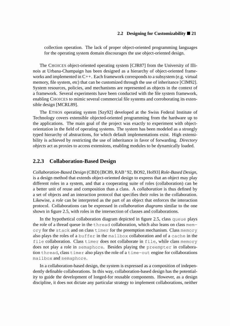
2.2 Designing for Customizability� 21
collection operation. The lack of proper object-oriented programming languagesfor the operating system domain discourages the use object-oriented design.
The CHOICES object-oriented operating system [CJR87] from the University of Illi-nois at Urbana-Champaign has been designed as a hierarchy of object-oriented frame-works and implemented in C++. Each framework corresponds to a subsystem (e.g. virtualmemory, file system, etc) that can be customized through the use of inheritance [CIM92].System resources, policies, and mechanisms are represented as objects in the context ofa framework. Several experiments have been conducted with the file system framework,enabling CHOICESto mimic several commercial file systems and corroborating its exten-sible design [MCRL89].
The ETHOS operating system [Szy92] developed at the Swiss Federal Institute ofTechnology covers extensible objected-oriented programming from the hardware up tothe applications. The main goal of the project was exactly to experiment with object-orientation in the field of operating systems. The system has been modeled as a stronglytyped hierarchy of abstractions, for which default implementations exist. High extensi-bility is achieved by restricting the use of inheritance in favor of forwarding.Directoryobjectsact as proxies to access extensions, enabling modules to be dynamically loaded.
2.2.3 Collaboration-Based Design
Collaboration-Based Design(CBD) [BC89, RAB+92, BO92, Hol93]Role-Based Design,is a design method that extends object-oriented design to express that an object may playdifferent roles in a system, and that a cooperating suite of roles (collaboration) can bea better unit of reuse and composition than a class. Acollaboration is thus defined bya set of objects and an interaction protocol that specifies their roles in the collaboration.Likewise, arole can be interpreted as the part of an object that enforces the interactionprotocol. Collaborations can be expressed incollaboration diagramssimilar to the oneshown in figure 2.5, with roles in the intersection of classes and collaborations.
In the hypothetical collaboration diagram depicted in figure 2.5, classqueue playsthe role of a thread queue in thethread collaboration, which also leans on classmem-ory for thestack and on classtimer for the preemption mechanism. Classmemoryalso plays the roles of abuffer in themailbox collaboration and of acache in thefile collaboration. Classtimer does not collaborate infile , while classmemorydoes not play a role insemaphore . Besides playing thepreempter in collabora-tion thread , classtimer also plays the role of atime-out engine for collaborationsmailbox andsemaphore .
In a collaboration-based design, the system is expressed as a composition of indepen-dently definable collaborations. In this way, collaboration-based design has the potential-ity to guide the development of longed-for reusable components. However, as a designdiscipline, it does not dictate any particular strategy to implement collaborations, neither
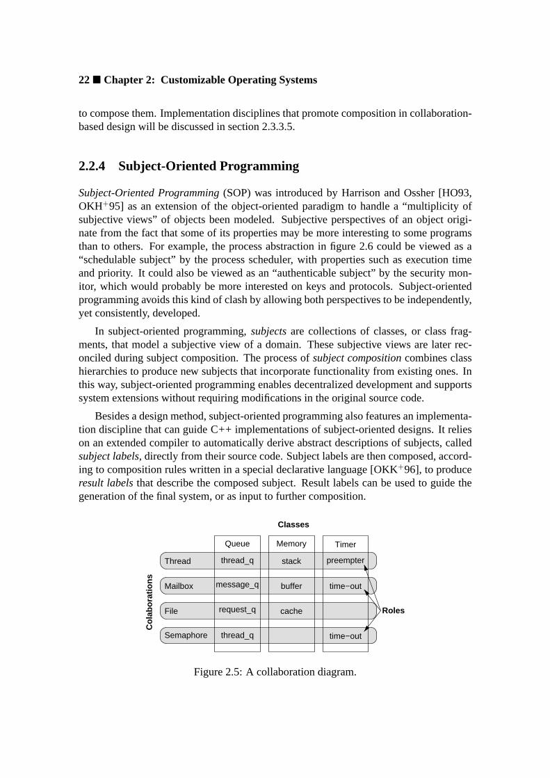
22� Chapter 2: Customizable Operating Systems
to compose them. Implementation disciplines that promote composition in collaboration-based design will be discussed in section 2.3.3.5.
2.2.4 Subject-Oriented Programming
Subject-Oriented Programming(SOP) was introduced by Harrison and Ossher [HO93,OKH+95] as an extension of the object-oriented paradigm to handle a “multiplicity ofsubjective views” of objects been modeled. Subjective perspectives of an object origi-nate from the fact that some of its properties may be more interesting to some programsthan to others. For example, the process abstraction in figure 2.6 could be viewed as a“schedulable subject” by the process scheduler, with properties such as execution timeand priority. It could also be viewed as an “authenticable subject” by the security mon-itor, which would probably be more interested on keys and protocols. Subject-orientedprogramming avoids this kind of clash by allowing both perspectives to be independently,yet consistently, developed.
In subject-oriented programming,subjectsare collections of classes, or class frag-ments, that model a subjective view of a domain. These subjective views are later rec-onciled during subject composition. The process ofsubject compositioncombines classhierarchies to produce new subjects that incorporate functionality from existing ones. Inthis way, subject-oriented programming enables decentralized development and supportssystem extensions without requiring modifications in the original source code.
Besides a design method, subject-oriented programming also features an implementa-tion discipline that can guide C++ implementations of subject-oriented designs. It relieson an extended compiler to automatically derive abstract descriptions of subjects, calledsubject labels, directly from their source code. Subject labels are then composed, accord-ing to composition rules written in a special declarative language [OKK+96], to produceresult labelsthat describe the composed subject. Result labels can be used to guide thegeneration of the final system, or as input to further composition.
Memory
stack
buffer
cache
Queue
thread_q
request_q
message_q
thread_q
time−out
Timer
time−out
preempterThread
Mailbox
File
Semaphore
Co
lab
ora
tio
ns
Classes
Roles
Figure 2.5: A collaboration diagram.

2.2 Designing for Customizability� 23
The use of subject-oriented programming at the operating system level can bring sev-eral benefits in regard to the subjective views it sustains. However, it may be a problem toexpress relationships that crosscut subjects in this model. For instance, the definition ofpriorities for the process subject may have implications for the management of messagesin the communication subsystem. This kind of collateral effect, or system-wide property,is not easily expressible by means of subject-specific composition rules.
2.2.5 Aspect-Oriented Programming
Aspect-Oriented Programming(AOP) was introduced by Kiczales [KLM+97] to dealwith non-functional properties of component-based systems. Most of the currentcomponent-based development strategies concentrate on defining and composing func-tional units, and do not properly address the representation of non-functional propertiescaptured during system design. In these strategies, properties such as synchronization,error handling, and security are usually expressed as small code fragments scattered overseveral components. Developing and maintaining such a kind of entangled code consti-tutes one of the biggest problems in component-based software engineering, for it ruptureswith important concepts like encapsulation and cohesion and compromises the softwarequality. Furthermore, a component that is hardwired to a specific environment will hardlybe reused in another.
Aspect-oriented programming captures non-functional properties in reusable unitscalled “aspects”. Aspects are specified inaspect-oriented languagesand wovenwithcomponents byaspect weaversto generate the target system (figure 2.7). This process
priority
nice
key
check
priority
nice
key
check
composer
ComposedSubject
SchedulableSubject
SecureSubject
Process Process
Process
Figure 2.6: Subject-oriented composition.

24� Chapter 2: Customizable Operating Systems
of combining aspects and components is instrumented byjoin points, which are elementsof the component language semantics understood by the aspect program and used forcoordination.
One of the major problems with aspect-oriented programming is the difficulty of sep-arating aspects from components during design, and subsequently implementing aspect-independent components. As mentioned before, some non-functional properties spon-taneously emerge during design, but a true aspect-oriented program is supposed to gomuch further in order to reach aspect independence. Moreover, an aspect-oriented designmethod, that besides aspects also addresses the traditional issues of functional compo-nents, is yet to be unveiled. Another open issue regards the absence of mechanisms tocheck for semantic preservation during the weaving process—depending on the complex-ity of join points, it is possible that accidental semantic modifications occur [Szy97].
The PURE [BSPSS00] system at the University of Magdeburg uses aspect-orientedprogramming to streamline the operating system, firstly getting rid of unnecessary com-ponents, but also modifying the source code of components in order to optimize themfor the conditions established by users. For example, dynamically bound references toobjects that are known not to vary are replaced by static binding.
2.2.6 Multiparadigm Design
More than a design method,Multiparadigm Designis the realization that no singleparadigm can cover all peculiarities of all domains: sometimes distinct paradigms haveto be combined in order to achieve a successful design. Innumerable combinations ofparadigms have been proposed for different domains [Hai86]; however, the combinationsthat involve object-orientation are of special interest for this thesis. Object-oriented de-sign methods are suitable to model most elements in an operating systems, but a fewelements simply do not fit correctly in the object model.
Each designer has a particular opinion about which elements fit in the object model
weaver
Program
Aspects Components
Figure 2.7: Aspect-oriented composition.

2.3 Implementing Customizable Designs� 25
and which are better represented in some other way. A few even insist that “everything”fits in the object model. However, the representation of some operating system elementsis quite controversial. For example, when one considers accessing the CPU’s controlregisters, sending a message to the CPU object sounds just natural, but for the moregeneric perspective, the CPU is one of those ubiquitous elements, that exists withoutneeding to be represented. Another contentious element is the process scheduler. Somedesigners model it as an object, some as a class operation of class process, and somesimply prefer to see it as an algorithm outside the object world. Multiparadigm designgives designers a chance to combine paradigms in order to solve this kind of conflict.
Some programming languages have been conceived to support the implementationof multiparadigm designs, the most famous of them being C++. Although commonlydefined as an object-oriented language, C++ was introduced by Stroustrup [Str86] as amultiparadigm language. Besides accommodating most object-oriented concepts, multi-ple inheritance inclusive, C++ supports a variety of other paradigms, including structured,family-based, generic programming, and static metaprogramming.
Coplien [Cop98] explored the multiparadigm characteristics of C++ to define a mul-tiparadigm design method that fuses object-oriented design with family-based and struc-tured design. The method guides an implementation-aware design, revealing the languageconstructs that better match each paradigm.
2.3 Implementing Customizable Designs
The development of software as an assemblage of reusable components has been soughtfor decades. Successive announcements have been made of methods that could pro-duce the desired reusable components, including modular programming in the seven-ties, object-oriented programming in the eighties and uncountable extensions to bothparadigms in the nineties. Only recently, however, the construction of software systemsbased on reusable, sometimes configurable, components began to prove effective. Evenso, software engineers still have to agree about a commoncomponent-based softwaredevelopment methodology. For the time being, they have to rely on a combination ofmethods and techniques, each contributing with elements that apply better to this or thatsituation.
This section considers the implementation of customizable operating systems basedon reusable components, trying to identify the pros and cons of each method.
2.3.1 Software Components
The growing interest on the development of software systems as arrangements of reusablecomponents has recently raised an intense discussion about what a software component

26� Chapter 2: Customizable Operating Systems
is, and what it is not. Similar discussions seem to arise among the software engineeringcommunity every time a technology achieves success, and forces whoever adopts the termto state his/her opinion about the controversy. Next, definitions forsoftware componentproposed by prominent authors are presented in order to render a brief snapshot of thecontroversy.
“A reusable software component is a logically cohesive, loosely coupledmodule that denotes a single abstraction.”
(Grady Booch [Boo87])
“By components we mean already implemented units that we use to enhancethe programming language constructs. These are used during programmingand correspond to the components in the building industry.”
(Ivar Jacobson [JCJO93])
“Reusable software components are self-contained, clearly identifiable piecesthat describe and/or perform specific functions, have clear interfaces, appro-priate documentation, and a defined reuse status.”
(Johannes Sametinger [Sam97])
“A software component is a unit of composition with contractually specifiedinterfaces and explicit context dependencies only. A software component canbe deployed independently and is subject to composition by third parties.”
(Clemens Szyperski [Szy97])
Booch extends the traditional concept of module to include the object-oriented notionof abstraction. For components in the realm of object-orientation, his definition also rec-ognizes that a class is often an inadequate construct to encapsulate a reusable abstraction(a module is adequate). Jacobson’s definition is quite vague and concentrates on com-position during system programming, at language level. Sametinger’s definition is widerand includes not only pieces of software implementation, but of software description too.He also stresses the importance of clear interfaces and proper documentation. Szyperski,among the selected authors, has the most restrictive definition, whereas it requests a com-ponent to be independently deployable and to be subject to composition by third parties.He also states that “a corollary of this definition is that software components are ‘binary’units that are composed without modifications” [Szy97]. This excludes systems that adoptsource code generation techniques to configure and/or adapt components at deploymenttime.
The discussion about the use of software components in the construction of cus-tomizable operating system, as addressed in this dissertation, does not intend to exclude
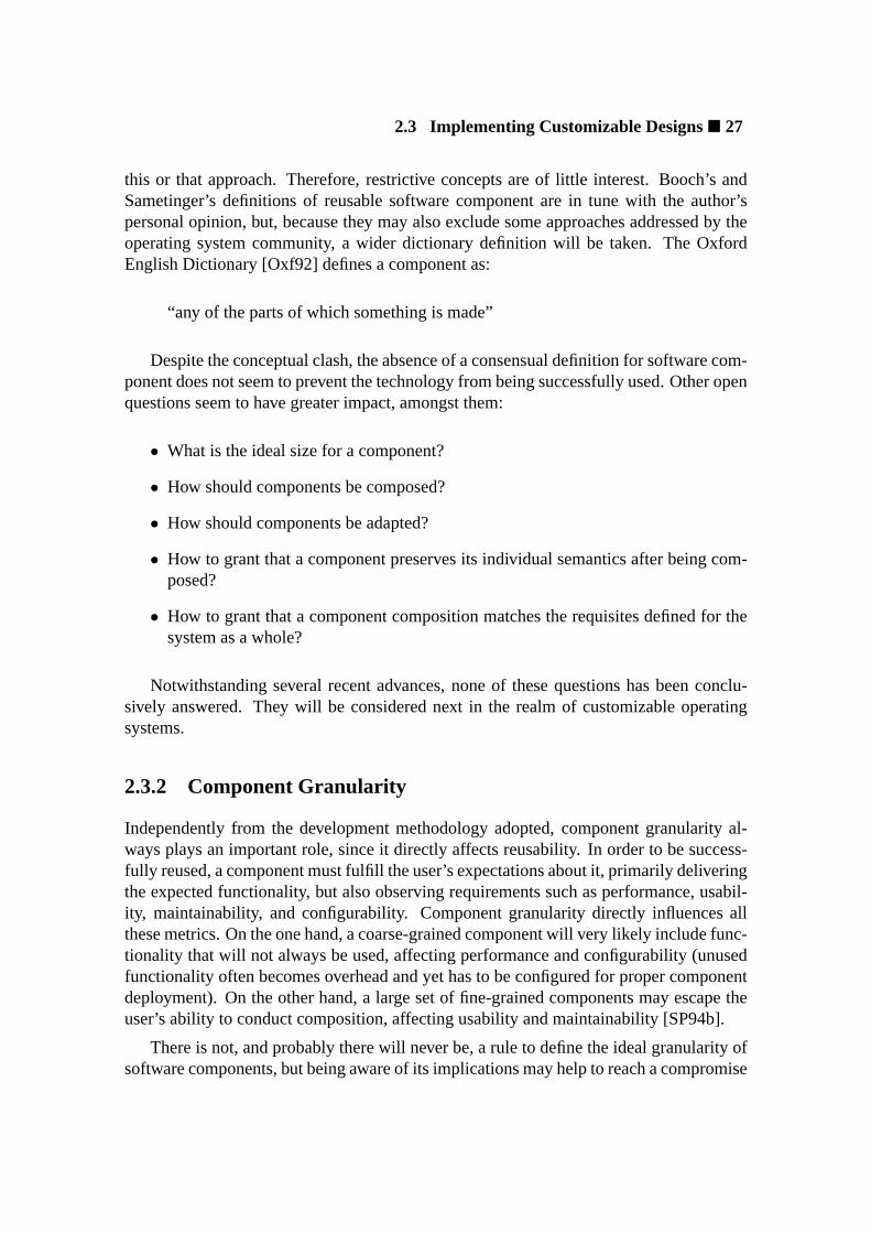
2.3 Implementing Customizable Designs� 27
this or that approach. Therefore, restrictive concepts are of little interest. Booch’s andSametinger’s definitions of reusable software component are in tune with the author’spersonal opinion, but, because they may also exclude some approaches addressed by theoperating system community, a wider dictionary definition will be taken. The OxfordEnglish Dictionary [Oxf92] defines a component as:
“any of the parts of which something is made”
Despite the conceptual clash, the absence of a consensual definition for software com-ponent does not seem to prevent the technology from being successfully used. Other openquestions seem to have greater impact, amongst them:
• What is the ideal size for a component?
• How should components be composed?
• How should components be adapted?
• How to grant that a component preserves its individual semantics after being com-posed?
• How to grant that a component composition matches the requisites defined for thesystem as a whole?
Notwithstanding several recent advances, none of these questions has been conclu-sively answered. They will be considered next in the realm of customizable operatingsystems.
2.3.2 Component Granularity
Independently from the development methodology adopted, component granularity al-ways plays an important role, since it directly affects reusability. In order to be success-fully reused, a component must fulfill the user’s expectations about it, primarily deliveringthe expected functionality, but also observing requirements such as performance, usabil-ity, maintainability, and configurability. Component granularity directly influences allthese metrics. On the one hand, a coarse-grained component will very likely include func-tionality that will not always be used, affecting performance and configurability (unusedfunctionality often becomes overhead and yet has to be configured for proper componentdeployment). On the other hand, a large set of fine-grained components may escape theuser’s ability to conduct composition, affecting usability and maintainability [SP94b].
There is not, and probably there will never be, a rule to define the ideal granularity ofsoftware components, but being aware of its implications may help to reach a compromise

28� Chapter 2: Customizable Operating Systems
generic
fewcoarse
easy to maintaineasy to compose
specialized
many
easy to reuse
fine
efficient
low
high
granularity
Figure 2.8: Component characteristics versus granularity.
between size and amount that will enable effective reuse2. The way granularity influencesother component characteristics is illustrated in figure 2.8.
Alternatives to handle the granularity compromise involve hierarchy and automation.Sometimes complex components can be built on simpler ones, leading to hierarchicalimplementations and making the granularity issue more manageable [Szy97]. Moreover,the advent of tools that support automatic composition will enable components to shrinkin size and grow in number without affecting usability and maintainability.
In the operating system scene, device driver modules and servers are still the mostcommon fashion of component deployment. Such components are usually coarse and,despite of some configurability, are not specialized to any particular operation mode. Inother words, there are no special versions of these components that implement specificfunctionality subsets. For example, if one wishes to use an input/output device for outputonly, one is not only forced to take unnecessary input functions, but also a non-optimizedversion of output functions (they are not optimized because they have been implementedto operate in the presence of input) [CSP91, And92, PAB+95].
As of today, there are few component-based operating systems. From them, two havequite divergent opinions about component granularity. The component libraries in theFLUX operating system toolkit, developed at the University of Utah [FBB+97], compriserelatively coarse components, basically device drivers and complete subsystems. Severalof these coarse components have recognized performance flaws and are aimed at “takeoff” support for new systems. Proper components are expected to replace them as thesystem matures. In contrast, the PURE system at the University of Magdeburg [SSPSS98]defines a large set of fine-grained components that can be composed to form low-levelabstractions. PURE recognizes that configuring such a large set of components is beyondmost users’ grasp and is currently working on tools to automate the process [BSPSS00].
2Coplien [Cop98] remarks that extremely large components usually result from poor application domainpartitioning.

2.3 Implementing Customizable Designs� 29
2.3.3 Component Composition
Software components are of no value if they cannot be composed to yield a properlyfunctioning system. Achieving a properly functioning composition, in turn, demands apredictable component interaction mechanism that ensures the preservation of each com-ponent’s semantics in the presence of others. Several such mechanisms have been pro-posed for applicative software, but few of them explicitly consider the peculiarities ofcomposition at system-level, so adaptations are usually required. Because the operatingsystem constitutes the most elementary form of run-time support, relying on advancedrun-time language constructs for system composition is usually not possible. Besides,the intrinsics of an operating system challenges for composition strategies that are ableto handle special circumstances such as the enforcement of properties that cross-cut com-ponent boundaries, the interaction of components that reside in different domains, thehandling of asynchronous events generated by the hardware, etc.
Subsequently, the most relevant composition mechanisms traditionally deployed atthe application-level will be described together with the implications of adopting them atsystem-level.
2.3.3.1 Interfaces
The interfaceof a component gathers the signatures of the operations that can be invokedon it, serving as a kind of “service contract” between its clients and providers. On oneside, such contracts define what clients can expect from a component and how they canuse it. On the other side, they define what providers have to implement to meet thecontracted services. Therefore, interfaces constitute the most elementary mechanism tosupport component composition, upon which more complex mechanisms can be built.
Interfaces on their on, however, are not enough to grant a properly functioning com-position, since they do not ensure semantic preservation in relation to external dependen-cies. For example, a component conceived to interact in a single-threaded environmentmight perform incorrectly in the presence of multiple threads, even though the interfacehas been properly observed. Furthermore, the operations in an interface are restricted tospecify functional aspects of components. Concerns about performance, availability, andother non-functional aspects are not adequately expressible via interfaces.
2.3.3.2 Contracts
In the sense of object composition, acontractis a kind of extended interface that, besidesthe syntactic part corresponding to operation signatures, also includes a semantic partconcerning behavioral aspects of components. The semantic annotations in a contractmay be formal or informal. Informal annotations are restricted to document the semanticsof a component, while formal annotations can be used to validate a composition.

30� Chapter 2: Customizable Operating Systems
Helm [HHG90] and Holland [Hol92] consequently explored the utilization of formalcontracts as means to support object composition. In their approach, a contract is definedas follows:
“... a contract defines the behavioral composition of a set of communicatingparticipants. Each contract specifies the following important aspects of be-havioral compositions. Firstly, it identifies the participants in the behavioralcomposition and their contractual obligations. Contractual obligations con-sist of type obligations, where the participant must support certain variablesand external interface, andcausal obligations, where the participant mustperform an ordered sequence of actions and make certain conditions true inresponse to these messages. Through causal obligations, contracts capturethe behavioral dependencies between objects. Secondly, the contract definesinvariants that participants cooperate to maintain. It also defines what ac-tions should be initiated to resatisfy the invariant, which as a matter of courseduring program execution will become false. Lastly, the contract specifiespreconditions on participants to establish the contract and the methods whichinstantiate the contract.”
(Richard Helm and Ian M. Holland [HHG90])
Although contracts have the benefit of generating object compositions that can beformally verified, the effort demanded to formally specify components mostly restricts itsuse to safety critical applications.
2.3.3.3 Design Patterns
Design patternsare catalogs of solutions to recurring problems in the object-orientationscene, among them object composition. The widely accepted catalog introduced byGamma et al. [GHJV95] describes each design pattern with four attributes: name, prob-lem description, solution description, and the consequences of adopting the respectivesolution. One important achievement of this catalog was the establishment of a ”taxon-omy” for object-oriented elementary architectures that may ease the interaction betweensoftware developers. Patterns are also used in combination with other strategies, in par-ticular with component frameworks [Joh92], to support composition.
The ADAPTERpattern (figure 2.9), for instance, can be used to adapt an existing com-ponent (Adaptee ), which has the expected functionality but an incompatible interface,to match the interface defined in a given framework (Target ). Adapter intercepts themessages exchanged betweenClient andAdaptee and makes the necessary adjust-ments to support the correct interaction between them. Components that otherwise wouldbe incompatible can be properly composed in this way.
2.3 Implementing Customizable Designs� 31
+operation()+operation()
Target Adaptee
+operation()
Adapter
Adaptee::operation()
Client
Figure 2.9: The ADAPTER design pattern.
Abstraction Implementor
+operation() imp−>operation()
Client
Refined_Abstraction Implementor_B
+operation()
Implementor_A
+operation()
imp
+operation()
Figure 2.10: The BRIDGE design pattern.
Another example is the BRIDGE pattern (figure 2.10), which can be used to decou-ple abstraction from implementation so that both can be independently extended by sub-classing. Bridges can be used to plug components (Implementor_A andImplemen-tor_B ) to a framework defined in terms of abstractions (Abstraction ).
2.3.3.4 Frameworks
An object-oriented framework[JF88, Deu89] is an arrangement of classes that capturesa reusable, usually domain-specific, design. Some of the classes in a framework are ab-stract and open for implementation inheritance, while others are concrete and encapsulatereusable implementations. Some frameworks also supply default implementations forabstract classes, so clients only have to implement the classes (or methods) that do not fit.
In awhitebox framework, existing functionality is reused and extended by inheritanceand overriding. It is so called because clients need to know the internal structure of theframework in order to use it. Conversely, in ablackbox framework[Joh97, Lar00], orcomponent framework, the relationships between components are defined exclusively interms of their interfaces, so that components can be reused without modifications. Com-position is done by selecting and plugging components to the framework (figure 2.11).

32� Chapter 2: Customizable Operating Systems
Framework
file
Components
select&
plug
link
thread
taskmem
tty
Figure 2.11: A component framework.
As Szyperski [SV98] observes, when compared to mechanisms in which componentsare simply “wired” together, a component framework has the important advantage ofbeing able to enforce system-wide properties like reliability, availability, security, andscalability. Even if individual components present such properties, arbitrary compositionswill seldom preserve them. However, the inclusion of specific elements in the frameworkcan sustain this kind or property.
A component framework is an attractive alternative to support composition at system-level. However, some component frameworks, especially those defined in terms of designpatterns, make extensive use of dynamic binding. In order to avoid severely compromis-ing performance, an operating system framework must rationalize the use of expensivelanguage constructs, reserving them to imperative cases.
The CHOICES [CIM92] system at the University of Illinois at Urbana-Champaigndefines a collection ofwhiteboxframeworks, one for each of its subsystems. Default im-plementations for the abstractions on each framework are provided, facilitating the con-struction of new systems. Default abstractions can be overridden or specialized throughinheritance. The X-KERNEL [HP91] at the University of Arizona defines a frameworkfor implementing network protocols in a similar way. Ablackboxframework is usedby the FLUX project [FBB+97] at the University of Utah to guide the linking of objectfiles (components). A more elaborate kind of component framework, that uses generativeprogramming techniques, will be presented in section 4.5.1.
2.3.3.5 Collaborations
Collaborations are the components in the realm ofcollaboration-based design[sec-tion 2.2.3]. A collaboration is defined by a set of objects and an interaction protocolthat specifies the roles of each object in the collaboration. A collaboration-based systemis thus a composition of independently definable collaborations.
Several strategies have been proposed to implement collaborations in such a way asto preserve the original design. VanHilst and Notkin [VN96b] express roles as parameter-ized classes (C++ class templates), which are in turn composed to yield the collaboratingclasses. The process is guided by class definitions analogous to the type equations used

2.3 Implementing Customizable Designs� 33
by Batory in the GenVoca model [BO92]. The use of templates for composition consider-ably reduces the occurrence of dynamic binding in the resulting system, hence enhancingperformance. Scalability, however, is a weak point in this approach, since the compositionof each individual role has to be specified.
Smaragdakis [Sma99] extended VanHilst and Notkin approach by mapping each col-laboration into a single parameterized class with a nested class for each of its roles. Col-laborations are composed in a hierarchical way by successively specifying one as param-eter to the next. This yields a composition scheme that directly matches the type equa-tions of GenVoca and requires less effort to specify compositions. Mezini [ML98] workonadaptive plug-and-play componentsfocuses on implementing collaboration-based de-signs as component frameworks.
2.3.3.6 Static Metaprogramming
Metaprograms3 are programs that represent and manipulate other programs or themselves.A static metaprogramis a metaprogram that runs before the code it produces is set torun. The most classical static metaprograms are compilers and preprocessors, which ma-nipulate an input program in order to translate it into another language or to modify itsstructure. Nevertheless, static metaprogramming is also used in programming languagesthat support parts of the input program to be evaluated at compile-time, the so-called mul-tilevel languages [GJ97]. The C++ programming language, for instance, supports staticmetaprogramming through mechanisms such as class and functiontemplates, expressionevaluation in constant initialization, and functioninlining [Str97, Vel95, Pes97].
In order to illustrate the case for static metaprogramming using C++ templates, thenatural number factorial calculator used by Czarnecki [CEG+98] is reproduced in figure2.12. The templateFactorial recursively multiplies its argument, while the templatespecializationFactorial<0> finishes the recursion. When invoked, this factorial func-tion is executed by the compiler, which simply includes the function result (an integer) inthe generated code. Therefore, the code generated by the compiler for the following twolines is identical:
cout « Factorial<7>::RET « ’\ n ’;cout « 5040 « ’\ n ’;
In the context of component-based systems, static metaprogramming can be used tosupport efficient composition when deployed in combination with some of the strategiesdescribed previously in this section. A static metaprogram can take components andcomposition rules as input and generate the corresponding program during the compila-tion process. When compared to composition assisted by external tools, i.e., tools thatare loosely integrated with the language used to specify components, a static metapro-gram has two main advantages: performance and correctness. A composition produced
3The Greek prefix “meta” stands for “after” or “beyond” and is used to denote a shift in level.

34� Chapter 2: Customizable Operating Systems
template <int n>struct Factorial { enum { RET = Factorial<n − 1>::RET ∗ n }; };
template <>struct Factorial <0> { enum { RET = 1 }; };
Figure 2.12: A statically metaprogrammed factorial calculator.
by a static metaprogram can perform better than a tool-based composition because it iscarried out along with the compilation of components, extending the possibilities for op-timizations. A carefully designed composition scheme can avoid most run-time overhead.Composition conducted by a static metaprogram also present benefits regarding correct-ness, whereas the metaprogram is written in the same language as the components and issubject to syntactic and semantic verifications by the same compiler.
As an example of how a static metaprogram can manipulate the input program, con-sider the profiler in figure 2.13. It can be used to measure the lifetime of any object withoutmodifying the respective classes. The parameterized classProfiler takes classTar-get as parameter and specializes it in such a way that a timer is started when objects arecreated and stopped when they are destroyed. One specialization ofProfiler is createdfor each target class, but as it is handled at compile-time, no extra code is generated butthe necessary to measure the lifetime.
#include <package.h>
namespace Profiled_Package{
template <class Target>class Profiler : public Target{public :
Profiler () { live (); }~ Profiler () { die (); }
private :void live (); // t0 <− current timevoid die (); // t <− current time − t0Time t0;
};
typedef Profiler<Package::Class_A> Class_A;// ...
typedef Profiler<Package::Class_Z> Class_Z;}
Figure 2.13: A statically metaprogrammed profiler that measures the lifetime of objects.

2.3 Implementing Customizable Designs� 35
Modifications on the clients’ side could be avoided as well, for instance, with the useof name spaces and conditional compilation4. If the original set of classes is defined inone name space and the profiled one in another, then clients can select the desired versionby including the proper header file and “using” the proper name space as shown bellow:
# ifdef PROFILED#include "profiled_package.h"using namespace Profiled_Package;#else#include "package.h"using namespace Package;#endif
Defining a component framework based on static metaprogramming techniques couldeliminate much of the overhead in conventional frameworks [SV98]. Indeed, staticmetaprogramming has been explored to support component composition in several ap-proaches other than frameworks, including collaboration-based design [VN96a, ML98,Sma99] and subject-oriented programming [OKH+95]. It has not been intensively ex-plored in aspect-oriented programming probably due to the presumption that aspects arewritten in aspect languages, but it could certainly be an aid for an aspect weaver.
2.3.4 Component Configuration
The previous sections addressed the customization of operating systems by selecting spe-cific components to take part in a system instance. This section considers the possibilitiesof using generic programming techniques to customize every single component in or-der to achieve the expected global configuration. Real systems will more likely combineboth approaches, first selecting a set of components and then configuring each of themaccordingly.
Generic Programming(GP) [MS89, Gog96, JLMS98, Aus99] is a programming disci-pline that promotes reusability by means of parameterization. Perhaps the most notoriousexample of generic programming is the C++Standard Template Library(STL) [Pla95],which decouples algorithms from the data structures on which they operate. STL orthog-onal design allows programmers to use STL data structures with their own algorithms,and to use STL algorithms with their own data structures. As a template library, STL ismostly handled at compile-time, thus profiting from numerous compiler optimizations.
Generic programming can also be used to make ordinary software components moreconfigurable. Thesegeneric componentsare able to adjust their behavior according toexternally defined parameters. Because generic components are instantiated at compile-time, customizing them usually does not affect their efficiency. When a generic compo-nent is instantiated with a particular set of parameters, a concrete component is generated.
4A class “wrapper” able to makeProfiler fully transparent will be discussed later in section 3.8.3.

36� Chapter 2: Customizable Operating Systems
template <int n_res, class Resource>class Allocator{public :
Allocator (){ for ( int i = 0; i < n_res; i++) used[i ] = false ; }
Resource∗ alloc() {int i ;for ( i = 0; ( i < n_res) && used[i ]; i++);return ( i == n_res ) ? 0 : ( used[i ] = true , &resource[i ]);
}
void free(Resource∗ res) {int i ;for ( i = 0; ( i < n_res) && (&resource[i ] != res ); i++);if ( i != n_res) used[i ] = false ;
}
private :bool used[n_res];Resource resource[n_res];
};
Figure 2.14: A simple generic resource allocator.
An example of generic component is depicted in figure 2.14. This simple resourceallocator is able to allocate and reclaim any kind of resource, as long as information aboutthe maximum number of units of that resource is supplied5. The parameterized classAllocator takes two parameters:n_res and Resource . The first stands for themaximum number of resources of the corresponding type, while the second designatesthe resource type. A statically allocated array of resourcesresource is created for laterallocation, and theused bitmap tracks resource utilization.
Indeed, this example goes beyond parameterized programming and uses C++ staticmetaprogramming features to completely embed the allocator into the client (no functioncalls are generated at all)6. A concrete allocator that allocates up to 16 buffers of 4 Kbytescould be instantiated as follows:
Allocator<16, char [4096]> allocator ;
5An allocator with a fixed number of resources may look strange for an application programmer, but iscertainly in order for a system programmer. In an operating system there are plenty of cases in which themaximum number of resources is known in advance (e.g., SCSI devices in a bus), or in which the cost ofdynamic allocation is not worth paying (e.g.i-nodes in a file system).
6If code replication becomes a problem, a set of allocation functions that ignores the type of resourcebeing allocated and operates solely on pointers and size information can be gathered in a base class for thegeneric allocator.

2.4 Summary� 37
Although not the only language to support generic programming, C++ has been thechoice for many generic component developers, which rely mostly on the template mech-anism. Template parameters in C++ are not restricted to types; they can also be constants,data structures, or even stretches of code. This makes component construction very flexi-ble, but not without its price. The resulting source code may become incomprehensible ifmany parameters are used, or if unconventional parameters are used.
2.4 Summary
A customizable operating systems is constructed to be configured in accordance withspecific requirements dictated by the hardware, users, or applications. In such a system,configuration must be explicitly controllable, so that clients can designate the features thatwill be active in the system at a given time. This is usually achieved with mechanismsthat adjust system control parameters and/or manipulate system parts.
The configuration mechanisms available to an operating system to accomplish cus-tomizability can be classified as static or dynamic. Static configuration mechanisms aredeployed to modify system characteristics before it begins to execute, influencing theprocess of link edition, compilation, or source code generation. In contrast, dynamic con-figuration mechanisms are deployed while the system is running. Common mechanismsinclude process creation, kernel extension, and reflection.
Static configuration mechanisms have advantages on performance and resource uti-lization, for they are not included on the final system. On the other hand, dynamic con-figuration mechanisms confer the system a higher degree of flexibility, for they supportthe system in reconfiguring itself to deal with unpredicted situations. In general, dy-namic configurability agrees with generic computing systems, in which applications arenot known in advance, while static configurability matches up dedicated computing sys-tems, which comprise a small set of applications (often a single one) whose requirementsare understood in advance. Knowing applications in advance allows dedicated systems toprofit from static configuration mechanisms without degrading flexibility, since the systemcan be pre-configured to include all the features that will be needed by the application(s).
An operating system modeled as an arrangement of software components can reacha high degree of customizability. Configuration is thus accomplished through the se-lection, adaptation, and combination of software components. Methodologies such asfamily-based design, object-oriented design, collaboration-based design, subject-orientedprogramming, aspect-oriented programming and multiparadigm combinations of thesehave the potentiality to guide the design of customizable operating systems by meansof concepts like variability and commonality analysis, domain decomposition, subjectiveviews of domain, and aspect separation.

38� Chapter 2: Customizable Operating Systems
During the development of component-based software, the definition of componentinterfaces is a fundamental activity. A component interface specifies the services pro-vided by a component, yielding a kind of service contract between its clients and suppli-ers. Such software components can be composed with a variety of techniques, includingdesign patters, frameworks, and generative programming, while generic programmingtechniques can assist internal configuration. Nevertheless, the development of customiz-able operating systems as collections of components introduces a series of new obstacles.Engineering software components of adequate granularity, adaptability, and composabil-ity, as well as mechanisms to assemble them efficiently and correctly, remains a challenge,indicating that more adequate design and implementation techniques are necessary.

Chapter 3
Application-Oriented System Design
In chapter 2, several mechanisms to support the construction of customizable operatingsystems have been described. From that study, one could conclude that, by adopting state-of-the-art software engineering techniques, it is possible to construct run-time supportsystems with a high degree of customizability. In particular, dedicated systems couldbenefit from statically configurable components to achieve the desired customizabilitywithout having to pay the high price of dynamic reconfiguration.
Nevertheless, a repository of system-level components and a mechanism to arrangethem together may not be enough to comply with the requirements of dedicated comput-ing systems. Ordinary run-time support systems frequently fail to deliver the expectedservices, or the expected service quality [And92, Mah94, DBM98]. Slicing one such asystem in a set of components will certainly not improve the case for applications.
This chapter presents a novel strategy to build component-based run-time support sys-tems that can be tailored according to the requirements of particular applications. Thisstrategy is defined around theApplication-Oriented System Designmethod, which cov-ers the development of application-oriented operating system from domain analysis toimplementation.
3.1 The Case for Application-Orientation
Historically, operating systems have been constructed aiming at abstracting physical re-sources in a way that is more convenient for the hardware than for applications. Undoubt-edly, the monolithic structure of early operating systems contributed to this scenario, forit must have been very difficult, if not impracticable, to customize such systems in orderto accomplish the demands of particular applications. The notion that applications haveto be adapted to the operating system was so established. Since then, a succession ofstandardizations has been freezing application program interfaces, thus helping to con-solidate the situation. Contemporary operating systems are suffocated by thick layers of

40� Chapter 3: Application-Oriented System Design
standards that keep the majority of the conceivable improvements unreachable for appli-cations [Pik00].
Besides failing to accompany the natural evolution of applications, many operatingsystems also fail to keep updated as regards software engineering. By comparing articlespublished in acclaimed scientific journals of both fields, operating systems and softwareengineering, one could even conclude that they do not concern the same science. Perhapsthis is also a consequence of extreme standardization, whereas there is little room fornew software engineering techniques in the constrained scenario of operating systems.Astonishingly, this is a very complex software scenario, which spans from hardware toapplications, and would greatly profit from modern software techniques. However, inreality, the obsolescence of the techniques deployed in some systems comes out to impactapplications.
Even modern operating systems that support customization have difficulties to matchup with application requirements. Mainly because they usually target the design of con-figurable features, the heart of any customization strategy, on standard compliance andon hardware aspects, and do not adequately address application requirements. Hence,an application programmer may be invited to select features such as POSIX or TCP/IPcompliance, or to select drivers for a certain hardware device, but seldom will have thechance to express that traditional features such as process and memory management arenot needed. Interestingly, this is one of the most typical operating modes for a dedicatedcomputing system.
Building an operating system as an aggregate of reusable components has the po-tentiality to considerably improve the situation, diminishing the gap between system andapplications. Nevertheless, component-based software engineering is just a means to con-struct systems that can be customized to fulfill the demands of particular applications. In-adequately modeled components, or inadequate mechanisms to select and combine com-ponents, may render the extra effort of building reusable components unproductive. Thegoal of application-driven customization can only be achieved if the system as a whole isdesigned considering the fulfillment of application requirements.
Furthermore, the way customization is typically carried out in component-based op-erating systems makes it difficult to pair with application requirements. As a rule, cus-tomization in these systems is delegated to end users, which are assisted by some sortof tool in selecting and combining components to produce an executable system. In thiscase, successfully customizing the operating system becomes conditioned to the knowl-edge the user has about the system. Hence, user-driven customization is entangled in thebalance of component granularity discussed in section 2.3.2:
• If components arecoarse-grained, the chance of an ordinary user, i.e., a user with-out deep knowledge about the operating system, to successfully conduct systemcustomization grows, but the probability that components will meet application re-quirements decreases proportionally.

3.2 Application-Oriented Operating Systems� 41
• If components arefine-grained, the chance that the system will match applicationrequirement grows, but it is likely that users will not be able to understand thepeculiarities of such a large collection of components, and will probably miss theproper configurations.
Improvements in user-driven configuration have been pursued by enabling compo-nents to be selected indirectly. The LINUX system, for instance, utilizes a mechanismto select kernel components through the features they implement. Instead of pointingout which components shall be included in the system, users can select the desired systemfeatures. Features, in turn, are interrelated by dependencies and mapped into components.Nevertheless, even if LINUX kernel components are coarse-grained (they are mainly de-vice drivers and subsystems) and will seldom satisfy the specific requirements of indi-vidual applications, selecting features from a list with approximately 700 options1 wouldbe considered a sordid activity by most users. A mechanism that allows applicationsthemselves to guide the configuration process would be more appropriate.
The considerations made so far relate to applications in general; the case for dedicatedcomputing systems is even worse. Dedicated systems execute specific sets of applicationsthat are defined in advance, so the requirements for the operating systems are also knownbeforehand. Theoretically, this should enable the operating system to be rightly cus-tomized to support the application. However, when a general-purpose operating systemis in scene, what usually happens is that applications get uncountable services that are notneeded, but still have to implement much of what is needed.
Notwithstanding, software engineering seems to be now in such an advanced stagethat it should be possible to produce an operating system that, besides scaling with thehardware, also scales with applications; that delivers all the functionality required by ap-plications in a form that is convenient for them; and that deduces application requirementsto automatically configure itself. Many of the related issues have already been addressedin the context of all-purpose computing byreflective systems. In order to comply with therequirements of high-performance dedicated systems, the subject is approached in thisthesis from the perspective of statically configurable component-based systems.
3.2 Application-Oriented Operating Systems
The expressionapplication-orientedis being introduced here to characterize operatingsystems that are strongly compromised with applications. A customizable operating sys-tem is said to be application-oriented if it can be customized to match the requirements ofparticular applications, rather than simply being customized to match standards or hard-
1The number of LINUX configurable kernel features has been estimated by execut-ing the following command in a system based on kernel version 2.2.14:grep CONFIG/usr/src/linux/configs/kernel-2.2.14-i386.config | wc -l .

42� Chapter 3: Application-Oriented System Design
ware aspects. The configurable features of such a system are directly derived from appli-cation requirements, so that applications themselves can drive the customization process.
The following enunciate unveils the foundations of an application-oriented operatingsystem:
An application-oriented operating system is only defined with regard to thecorresponding application(s), for which it implements the necessary run-timesupport that is delivered as requested.
It also yields the following corollaries:
• An application-oriented operating system, in contrast to an all-purpose one, is al-ways associated with a particular application (or with a particular set of applica-tions). This intentionally restricts the scope of the proposed definition to dedi-cated computing systems, for which the corresponding applications are known inadvance. It also favors static configuration mechanisms in detriment of dynamicones.
• An application-oriented operating system has to implement the run-time featuresthat are necessary to support the application, neither less nor more. It is straight-forward to understand why the system should not implement less than the neces-sary features, but for an application-oriented system, delivering more than what isnecessary should be avoided as well. Included features that are not used by theapplication, besides affecting the average system quality (performance, resourceutilization, configurability, etc), may complicate the matching with application re-quirements.
• The features implemented by an application-oriented operating system must be de-livered to the corresponding application as they have been requested. Hence, exter-nally visible interfaces must be defined in the context of applications to be realizedin the context of the operating system with the necessary internal adjustments.
The main contribution of this dissertation is a design method that addresses the is-sues involved in the construction of application-oriented operating systems. The pro-posed design method, namelyApplication-Oriented System Design(AOSD), covers thedevelopment of system-level software from domain analysis to implementation, reusingstate-of-the-art software engineering concepts and techniques when possible, and defin-ing novel ones when necessary. A new design notation has been suppressed in favor oftheUnified Modeling Language(UML) [BRJ99], though extensions and simplificationsto this language will be frequently practiced.

3.3 Domain Analysis and Decomposition� 43
3.3 Domain Analysis and Decomposition
Although no design can go further than its perception of the corresponding problem do-main, domain analysis and operating systems are subjects that seldom come together. Thefact that the operating system domain is basically made of conventions, many of whichestablished long ago in projects such as THE [Dij68] and MULTICS [Org72], seems tohave fastened it to a “canonical” partitioning. This partitioning includes abstractions suchas process, file, and semaphore, and is taken “as-is” by most designers. Indeed, it is nowconsolidated by standards on one side and by the hardware on the other, leaving very littleroom for new interpretations.
Notwithstanding this, revisiting the problem domain during the design of a new op-erating system would probably reveal abstractions that are better tuned with contempo-rary applications. For example, the triple (process, file, message passing) could be re-placed by persistent communicating active objects. Actually, most run-time platformsfeature this perspective of the operating system domain through a middleware layer suchas CORBA [OMG01] and JAVA [SUN01]. However, the middleware approach goes theopposite direction of application-orientation, whereas it further generalizes an alreadygeneric system.
Nevertheless, even if one endures domain analysis knowing that decomposition willhave to be carried out respecting the boundaries dictated by standards, programming lan-guages, and hardware, there is at least one important reason to do it: to avoid the mono-lithic representation of abstractions. If an application-oriented operating system is to bethe output of design, capturing application-specific perspectives of each abstraction andmodeling them as independently deployable units, as suggested bysubject-oriented pro-gramming[section 2.2.4], is far more adequate than the monolithic approach. After all,the product of domain engineering is not a single system, but a collection of reusablesoftware artifacts that model domain entities and can be used to build several systems.
3.3.1 Application-Oriented Domain Decomposition
An application-oriented decomposition of the problem domain can be obtained, in princi-ple, following the guidelines ofobject-oriented decomposition[section 2.2.2]. However,some subtle yet important differences must be considered. First, object-oriented decom-position gathers objects with similar behavior in class hierarchies by applying variabilityanalysis to identify how one entity specializes the other. Besides leading to the famous“fragile base class” problem [MS98], this policy assumes that specializations of an ab-straction (i.e.subclasses) are only deployed in presence of their more generic versions(i.e. superclasses).
Applying variability analysis in the sense offamily-based design[section 2.2.1] to pro-duce independently deployable abstractions, modeled as members of a family, can avoidthis restriction and improve on application-orientation. Certainly, some family members

44� Chapter 3: Application-Oriented System Design
will still be modeled as specializations of others, as inincremental system design[sec-tion 2.2.1.1], but this is no longer an imperative rule. For example, instead of modelingconnection-oriented as a specialization of connectionless communication (or vice-versa),what would misuse a network that natively operates in the opposite mode, one couldmodel both as autonomous members of a family.
A second important difference between application-oriented and object-oriented de-composition concerns environmental dependencies. Variability analysis, as carried out inobject-oriented decomposition, does not emphasizes the differentiation of variations thatbelong to the essence of an abstraction from those that emanate from the execution sce-narios being considered for it. Abstractions that incorporate environmental dependencieshave a smaller chance of being reused in new scenarios, and, given that an application-oriented operating system will be confronted with a new scenario virtually every time anew application is defined, allowing such dependencies could severely hamper the system.
Nevertheless, one can reduce such dependencies by applying the key concept ofaspect-oriented programming[section 2.2.5], i.e. aspect separation, to the decompositionprocess. By doing so, one can tell variations that will shape new family members fromthose that will yield scenario aspects2. For example, instead of modeling a new memberfor a family of communication mechanisms that is able to operate in the presence of mul-tiple threads, one could model multithreading as a scenario aspect that, when activated,would lock the communication mechanism (or some of its operations) in a critical section.
The phenomenon of mixing scenario aspects and abstractions seems to happen spon-taneously in most other design methods, so learning to avoid it may require some practice.Perhaps the most critical point is the fact that the majority of operating systems are con-ceived with an implementation platform in mind, which is often better understood than thecorresponding problem domain. In principle, there is nothing wrong in studying the targetplatform in details before designing the system, actually it may considerably save time,but designers tend to misrepresent abstractions while considering how they will be imple-mented in the chosen platform. In an application-oriented system design, this knowledgeabout implementation details should be driven to identify and isolate scenario aspects. Ingeneral, aspects such as identification, sharing, synchronization, remote invocation, au-thentication, access control, encryption, profiling, and debugging can be represented asscenario aspects.
Building families of scenario-independent abstractions and identifying scenario as-pects are the main activities in application-oriented domain decomposition, but certainlynot the only ones. The primary strategy to add functionality to a family of abstractionsis the definition of new members, but sometimes it is desirable to extend the behaviorof all members at once. Specializing each member would double the cardinality of thefamily. Application-oriented system design deals with cases like this by modeling theextended functionality as aconfigurable feature. Just like scenario aspects, configurable
2The representation of scenario aspects will be discussed later in section 3.5, for now it is only importantto avoid modeling unnecessary family members.

3.3 Domain Analysis and Decomposition� 45
features modify the behavior of all members of a family when activated, but, unlike those,are not transparent. One could say that scenario aspects have “push” semantics, whileconfigurable features have “pull”.
A configurable feature encapsulates common data structures and algorithms that areuseful to implement a family’s feature, but leave the actual implementation up to eachfamily member. Abstractions are free to reuse, extend, or override what is provided in aconfigurable feature, but are requested to behave accordingly when the feature is enabled.
The case for configurable features can be illustrated with a family of networks andfeatures such as multicasting, in-order delivery, and error detection. If new family mem-bers were to be modeled for each such a feature, a family of 10 networks subjected to 10features could grow up to1010 members. Modeling this kind of feature as a scenario as-pect is usually not possible either, since its implementation would have to be specializedto consider particular network architectures.
Another relevant issue to be considered during domain decomposition is how abstrac-tions of different families interact. Capturing ad-hoc relationships between families dur-ing design can be useful to model reusable software architectures, helping to solve one ofthe biggest problems in component-based software engineering: how to tell correct mean-ingful component compositions from unusable ones. A reusable architecture avoids thisquestion by only allowing predefined compositions to be carried out. For example, onecould determine that the members of a family of process abstractions must use the familyof memory to load code and data, avoiding an erroneous composition with members ofthe file family. In application-oriented system design, reusable architectures are capturedin component frameworks that define how abstractions of distinct families may interact.Although such frameworks are defined much later in the design process, taking note ofad-hoc relationships during domain decomposition can considerably ease that activity.
An overview of the process of application-oriented domain decomposition is pre-sented in figure 3.1. In summary, it is a multiparadigm domain analysis method thatpromotes the construction of application-oriented operating systems by decomposing thecorresponding domain in families of reusable, scenario-independent abstractions and therespective scenario aspects. Reusable system architectures are envisioned by the identifi-cation of inter-family relationships that will later build component frameworks.
3.3.2 An Example of Domain Decomposition
In order to illustrate the process of application-oriented decomposition, the domain ofhigh-performance communication in clusters of workstations will be decomposed next.This experiment has been realized with the collaboration of RWCP Laboratory for Par-allel and Distributed Systems at GMD that currently investigates means to facilitate theconstruction of grid and mesh-based scientific applications [GGD01]. The members ofthis group played the role of domain experts for a simplified use case analysis [JCJO93]

46� Chapter 3: Application-Oriented System Design
DomainProblem
Families ofAbstractions
ScenarioAspects
FamilyRelations
Figure 3.1: An overview of application-oriented domain decomposition.
that produced the vocabulary in table 3.1.
active messages ARMR/ARMW asynchronous sendATM capability channelcollective operations datagram debugging supportDSM end-point Ethernetgroup communication high bandwidth linklocation transparency low latency mailboxMPI multithreading Myrinetport protection PVMreliability SCI sharingstream synchronous send user-level
Table 3.1: A vocabulary regarding the domain of high-performance communication inclusters of workstations.
Based on this perception of the problem domain, application-oriented decompositionbegins by applying commonality/variability analysis to identify the families of abstrac-tions that build up the domain. For example,Myrinet , SCI , Ethernet , andATMcould be gathered in a family of networks, with a member for each network technology.The family would abstract what these networks have in common (e.g. the ability to trans-mit and receive data), while members would make evident the technological differencesamong them that are relevant to applications. Similarly,port andmailbox could starta family of communication end-points, whiledatagram andstream could be gatheredin a family of communication strategies.
Some of the keywords in table 3.1, however, clearly do not designate abstractions.High bandwidth andlow latency , for instance, are non-functional requirementsthat have to be taken in consideration during the design of the system as a whole. This kindof global propertyis quite different from those that can be enabled and disabled at users’wish. The support formultithreading , for instance, is a property that affects all ab-stractions in the domain, but not permanently. It could be modeled as ascenario aspect.Configurable properties that originate from an execution scenario but that are only mean-ingful to specific families can be modeled asprivate scenario aspectsfor those families.For example, anasynchronous communication system could be obtained exclusively
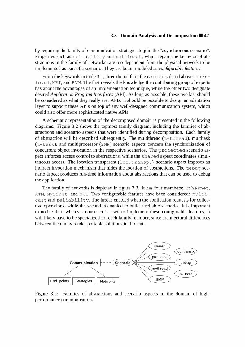
3.3 Domain Analysis and Decomposition� 47
by requiring the family of communication strategies to join the “asynchronous scenario”.Properties such asreliability andmulticast , which regard the behavior of ab-stractions in the family of networks, are too dependent from the physical network to beimplemented as part of a scenario. They are better modeled asconfigurable features.
From the keywords in table 3.1, three do not fit in the cases considered above:user-level , MPI, andPVM. The first reveals the knowledge the contributing group of expertshas about the advantages of an implementation technique, while the other two designatedesiredApplication Program Interfaces(API). As long as possible, these two last shouldbe considered as what they really are: APIs. It should be possible to design an adaptationlayer to support these APIs on top of any well-designed communication system, whichcould also offer more sophisticated native APIs.
A schematic representation of the decomposed domain is presented in the followingdiagrams. Figure 3.2 shows the topmost family diagram, including the families of ab-stractions and scenario aspects that were identified during decomposition. Each familyof abstraction will be described subsequently. The multithread (m-thread ), multitask(m-task ), and multiprocessor (SMP) scenario aspects concern the synchronization ofconcurrent object invocation in the respective scenarios. Theprotected scenario as-pect enforces access control to abstractions, while theshared aspect coordinates simul-taneous access. The location transparent (loc.transp. ) scenario aspect imposes anindirect invocation mechanism that hides the location of abstractions. Thedebug sce-nario aspect produces run-time information about abstractions that can be used to debugthe application.
The family of networks is depicted in figure 3.3. It has four members:Ethernet ,ATM, Myrinet , andSCI . Two configurable features have been considered:multi-cast andreliability . The first is enabled when the application requests for collec-tive operations, while the second is enabled to build a reliable scenario. It is importantto notice that, whatever construct is used to implement these configurable features, itwill likely have to be specialized for each family member, since architectural differencesbetween them may render portable solutions inefficient.
Scenario
SMP
protected
m−thread
shared
m−task
debug
loc. transp.
Communication
Strategies NetworksEnd−points
Figure 3.2: Families of abstractions and scenario aspects in the domain of high-performance communication.

48� Chapter 3: Application-Oriented System Design
Ethernet Myrinet SCIATM
Networkreliability
multicast
Figure 3.3: A family of networks in the domain of high-performance communication.
The family of communication strategies is shown in figure 3.4. It features six mem-bers that support the following strategies: connectionless communication (Datagram ),connection-oriented communication (Stream ), asynchronous write to a memory regionon a remote host (ARMW), the respective read operation (ARMR), active messages (AM),and distributed shared memory (DSM). BothAMandDSMare modeled in terms ofARMW.DSMalso reusesARMR. Two private scenario aspects have been modeled for this family:synchronous andasynchronous . The first scenario modifies the semantics of thecommunication mechanisms in such a way that the send operation (or equivalent) onlyconcludes when the destination application completely receives the data, while the sec-ond implies in the send operation returning as soon as possible. Besides, two configurablefeatures have been modeled: group communication (group comm. ) andbuffering .The first is used to implement collective operations, while the second supports the familyin implementing theasynchronous scenario.
The third family of abstractions is depicted in figure 3.5. It concerns end-points for thefamily of communication strategies, thus being the family that will be used more often byapplications. It includes the following members:1-to-1 channel (Connection ), n-to-1channel (Port ), n-to-n channel (Mailbox ), active message handler (AM Handler ),and memory segments for asynchronous remote operations (ARM Segment) and dis-tributed shared memory (DSM Segment). No private scenario aspects or configurablefeatures were modeled.
ARMR
DSMAM
buffering
groupcomm. Communication
Strategies
Datagram Stream ARMW
synchronous
asynchronous
Figure 3.4: A family of communication strategies in the domain of high-performancecommunication.

3.4 Families of Scenario-Independent Abstractions� 49
During the decomposition of the domain of high-performance communication in clus-ters of workstations, some fragments of reusable system architecture became evident: thefamily of communication strategiesusesthe family of networks, and both areinterfacedby the family of end-points. This would be recalled when defining a component frame-work for the high-performance communication system in question.
The following sections describe how a preliminary design specification produced dur-ing application-oriented domain decomposition can be refined to yield a detailed specifi-cation that can be used to guide the implementation of an application-oriented operatingsystem.
3.4 Families of Scenario-Independent Abstractions
During application-oriented domain decomposition, scenario-independent abstractionsare identified and grouped in families according to what they have in common. The subse-quent phase in application-oriented system design is the refinement of these abstractionsin order to define the software components that will implement them.
The first refinement to be performed is the adjustment of the magnitude of componentsin relation to abstractions. The basic idea is to keep a 1-to-1 relation, preserving confor-mity with the domain. However, it may happen that some entities in the domain are toocoarse-grained to be modeled as a single component (e.g. a file system), or to primitiveto be directly exposed to application programmers (e.g. an FPU). As explained earlier,excessively large components will likely miss the target on application-orientation, whileexcessively small components will likely flop on user-friendship.
The balance “as simple as possible, but still application-ready” is the goal to be pur-sued in this phase of design. Larger, more complex abstractions can be implemented asan assemblage of components, while elementary entities, that do not characterize abstrac-tions, can be embedded in other components according to the criterion of functional cohe-sion. Data structures and algorithms that are common to several families of abstractionscan be collected inutility classesto be reused during the construction of actual compo-nents. Although a precise “algorithm” to reach such a balance does not exist, chapter 4
AMHandler
ARMSegment
DSMSegmentPort MailboxConnection
CommunicationEnd−poits
Figure 3.5: A family of communication end-points in the domain of high-performancecommunication.
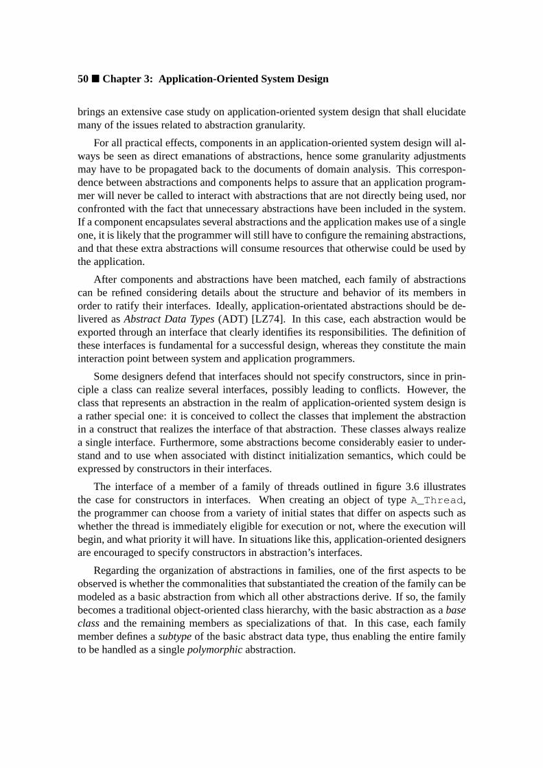
50� Chapter 3: Application-Oriented System Design
brings an extensive case study on application-oriented system design that shall elucidatemany of the issues related to abstraction granularity.
For all practical effects, components in an application-oriented system design will al-ways be seen as direct emanations of abstractions, hence some granularity adjustmentsmay have to be propagated back to the documents of domain analysis. This correspon-dence between abstractions and components helps to assure that an application program-mer will never be called to interact with abstractions that are not directly being used, norconfronted with the fact that unnecessary abstractions have been included in the system.If a component encapsulates several abstractions and the application makes use of a singleone, it is likely that the programmer will still have to configure the remaining abstractions,and that these extra abstractions will consume resources that otherwise could be used bythe application.
After components and abstractions have been matched, each family of abstractionscan be refined considering details about the structure and behavior of its members inorder to ratify their interfaces. Ideally, application-orientated abstractions should be de-livered asAbstract Data Types(ADT) [LZ74]. In this case, each abstraction would beexported through an interface that clearly identifies its responsibilities. The definition ofthese interfaces is fundamental for a successful design, whereas they constitute the maininteraction point between system and application programmers.
Some designers defend that interfaces should not specify constructors, since in prin-ciple a class can realize several interfaces, possibly leading to conflicts. However, theclass that represents an abstraction in the realm of application-oriented system design isa rather special one: it is conceived to collect the classes that implement the abstractionin a construct that realizes the interface of that abstraction. These classes always realizea single interface. Furthermore, some abstractions become considerably easier to under-stand and to use when associated with distinct initialization semantics, which could beexpressed by constructors in their interfaces.
The interface of a member of a family of threads outlined in figure 3.6 illustratesthe case for constructors in interfaces. When creating an object of typeA_Thread ,the programmer can choose from a variety of initial states that differ on aspects such aswhether the thread is immediately eligible for execution or not, where the execution willbegin, and what priority it will have. In situations like this, application-oriented designersare encouraged to specify constructors in abstraction’s interfaces.
Regarding the organization of abstractions in families, one of the first aspects to beobserved is whether the commonalities that substantiated the creation of the family can bemodeled as a basic abstraction from which all other abstractions derive. If so, the familybecomes a traditional object-oriented class hierarchy, with the basic abstraction as abaseclassand the remaining members as specializations of that. In this case, each familymember defines asubtypeof the basic abstract data type, thus enabling the entire familyto be handled as a singlepolymorphicabstraction.
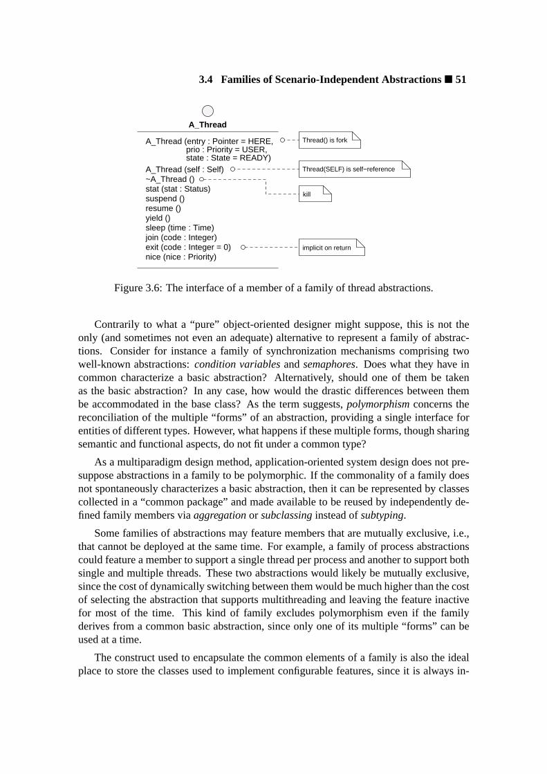
3.4 Families of Scenario-Independent Abstractions� 51
Thread(SELF) is self−reference
kill
Thread() is forkA_Thread (entry : Pointer = HERE, prio : Priority = USER, state : State = READY)
A_Thread (self : Self)
nice (nice : Priority)exit (code : Integer = 0)join (code : Integer)sleep (time : Time)yield ()resume ()suspend ()stat (stat : Status)~A_Thread ()
A_Thread
implicit on return
Figure 3.6: The interface of a member of a family of thread abstractions.
Contrarily to what a “pure” object-oriented designer might suppose, this is not theonly (and sometimes not even an adequate) alternative to represent a family of abstrac-tions. Consider for instance a family of synchronization mechanisms comprising twowell-known abstractions:condition variablesandsemaphores. Does what they have incommon characterize a basic abstraction? Alternatively, should one of them be takenas the basic abstraction? In any case, how would the drastic differences between thembe accommodated in the base class? As the term suggests,polymorphismconcerns thereconciliation of the multiple “forms” of an abstraction, providing a single interface forentities of different types. However, what happens if these multiple forms, though sharingsemantic and functional aspects, do not fit under a common type?
As a multiparadigm design method, application-oriented system design does not pre-suppose abstractions in a family to be polymorphic. If the commonality of a family doesnot spontaneously characterizes a basic abstraction, then it can be represented by classescollected in a “common package” and made available to be reused by independently de-fined family members viaaggregationor subclassinginstead ofsubtyping.
Some families of abstractions may feature members that are mutually exclusive, i.e.,that cannot be deployed at the same time. For example, a family of process abstractionscould feature a member to support a single thread per process and another to support bothsingle and multiple threads. These two abstractions would likely be mutually exclusive,since the cost of dynamically switching between them would be much higher than the costof selecting the abstraction that supports multithreading and leaving the feature inactivefor most of the time. This kind of family excludes polymorphism even if the familyderives from a common basic abstraction, since only one of its multiple “forms” can beused at a time.
The construct used to encapsulate the common elements of a family is also the idealplace to store the classes used to implement configurable features, since it is always in-
52� Chapter 3: Application-Oriented System Design
Caption
use
dependency
specializationMember 1 Member 2 Member 3
Member 4
feature 1config
feature 2config.
Family
Figure 3.7: Notation to represent a family of abstractions.
corporated by all members. Configurable features dictate particular conditions to abstrac-tions, but unlike scenario aspects, are not transparent. When an abstraction is notified thata configurable feature has been enabled, it has to modify its behavior accordingly. Never-theless, the implementation of such configurable features across the members of a samefamily can usually be accomplished deploying common data structures and algorithms,which can be modeled as classes in the family’s common package. These classes can bereused, specialized, or overridden by each family member.
A typical family of abstractions can be represented using the notation illustrated infigure 3.7. The correspondence of abstractions and components in an application-orientedsystem design allowsfamily diagramsto fuse elements from both logical and componentview. A family is represented as a tree, with members connected through dependencyrelationships, and themselves depending or specializing each other. The family’s commonpackage is implicitly represented, unless configurable features have been modeled forthe family. In this case, they appear connected to the root of the tree by means of userelationships.
While refining the specification of families and their members, it is also important toconsider inter-family relationships. Families often rely on abstractions from other familiesto deliver the contracted services. For example, a family of process abstractions may relyon a family of synchronization abstractions to coordinate concurrent execution. Wheneverpossible, inter-family relationships should be expressed without making the case for aparticular member of the supplier family, so that configurability is not constrained. If afamily makes a superfluous choice for a mutually exclusive member of another family, itimplicitly configures that family, preventing the application programmer from doing so,and reducing the number of valid system configurations.
Suppose for instance that familyB of figure 3.8 is mutually exclusive (i.e. only oneof B1, B2, andB3 can be used at a time). Defining relationshipR2 would implicitlyexclude membersB2 andB3 from been used when familyA is deployed. Evidently, thisis not an issue if familyA really depends on memberB1. Indeed, failing to representthis relationship would make room for erroneous configurations in this case. However,
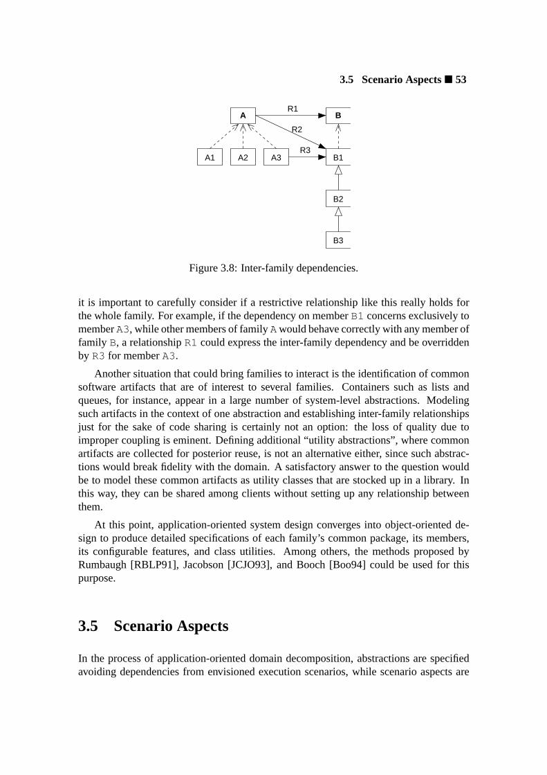
3.5 Scenario Aspects� 53
B
B1
B2
B3
A1 A2
A
A3
R1
R3
R2
Figure 3.8: Inter-family dependencies.
it is important to carefully consider if a restrictive relationship like this really holds forthe whole family. For example, if the dependency on memberB1 concerns exclusively tomemberA3, while other members of familyAwould behave correctly with any member offamily B, a relationshipR1 could express the inter-family dependency and be overriddenby R3 for memberA3.
Another situation that could bring families to interact is the identification of commonsoftware artifacts that are of interest to several families. Containers such as lists andqueues, for instance, appear in a large number of system-level abstractions. Modelingsuch artifacts in the context of one abstraction and establishing inter-family relationshipsjust for the sake of code sharing is certainly not an option: the loss of quality due toimproper coupling is eminent. Defining additional “utility abstractions”, where commonartifacts are collected for posterior reuse, is not an alternative either, since such abstrac-tions would break fidelity with the domain. A satisfactory answer to the question wouldbe to model these common artifacts as utility classes that are stocked up in a library. Inthis way, they can be shared among clients without setting up any relationship betweenthem.
At this point, application-oriented system design converges into object-oriented de-sign to produce detailed specifications of each family’s common package, its members,its configurable features, and class utilities. Among others, the methods proposed byRumbaugh [RBLP91], Jacobson [JCJO93], and Booch [Boo94] could be used for thispurpose.
3.5 Scenario Aspects
In the process of application-oriented domain decomposition, abstractions are specifiedavoiding dependencies from envisioned execution scenarios, while scenario aspects are
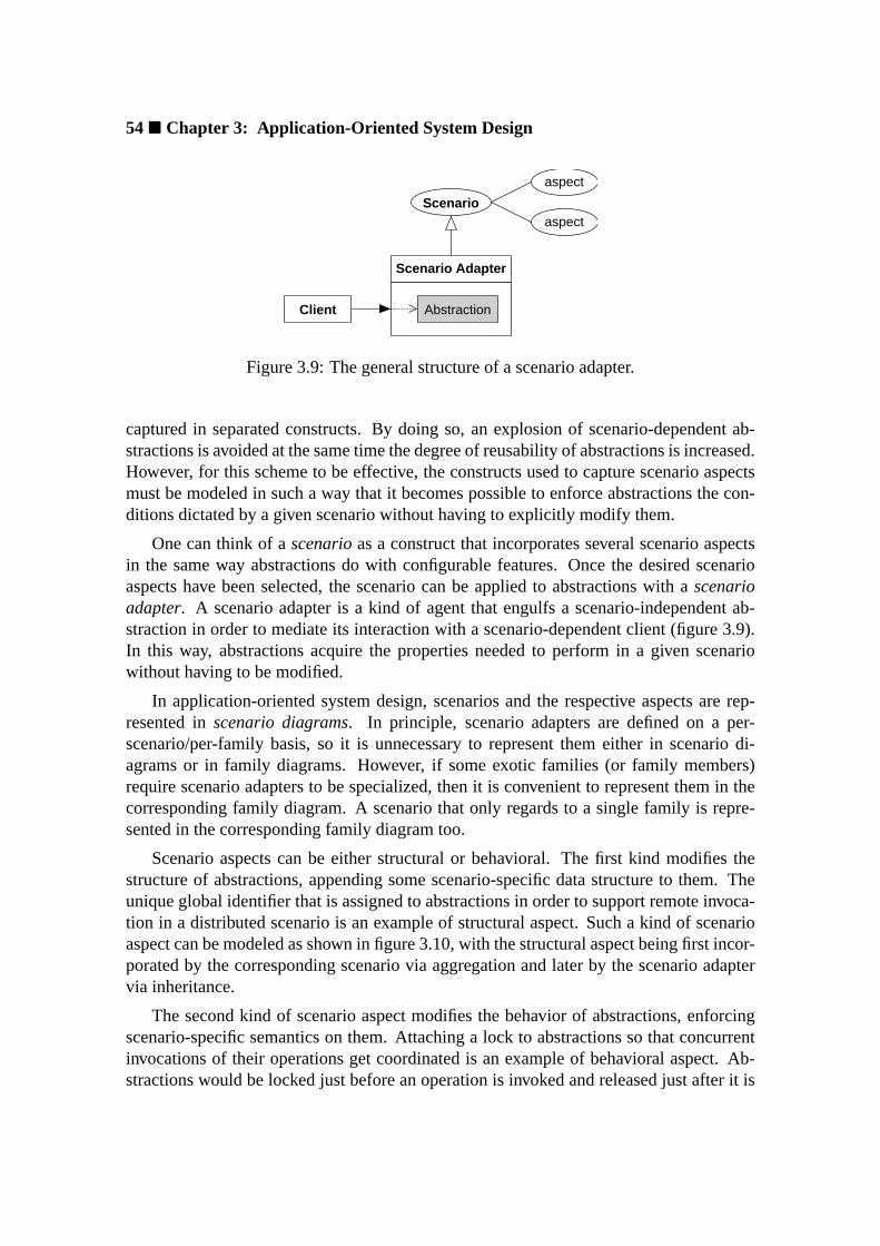
54� Chapter 3: Application-Oriented System Design
AbstractionClient
Scenario Adapter
Scenarioaspect
aspect
Figure 3.9: The general structure of a scenario adapter.
captured in separated constructs. By doing so, an explosion of scenario-dependent ab-stractions is avoided at the same time the degree of reusability of abstractions is increased.However, for this scheme to be effective, the constructs used to capture scenario aspectsmust be modeled in such a way that it becomes possible to enforce abstractions the con-ditions dictated by a given scenario without having to explicitly modify them.
One can think of ascenarioas a construct that incorporates several scenario aspectsin the same way abstractions do with configurable features. Once the desired scenarioaspects have been selected, the scenario can be applied to abstractions with ascenarioadapter. A scenario adapter is a kind of agent that engulfs a scenario-independent ab-straction in order to mediate its interaction with a scenario-dependent client (figure 3.9).In this way, abstractions acquire the properties needed to perform in a given scenariowithout having to be modified.
In application-oriented system design, scenarios and the respective aspects are rep-resented inscenario diagrams. In principle, scenario adapters are defined on a per-scenario/per-family basis, so it is unnecessary to represent them either in scenario di-agrams or in family diagrams. However, if some exotic families (or family members)require scenario adapters to be specialized, then it is convenient to represent them in thecorresponding family diagram. A scenario that only regards to a single family is repre-sented in the corresponding family diagram too.
Scenario aspects can be either structural or behavioral. The first kind modifies thestructure of abstractions, appending some scenario-specific data structure to them. Theunique global identifier that is assigned to abstractions in order to support remote invoca-tion in a distributed scenario is an example of structural aspect. Such a kind of scenarioaspect can be modeled as shown in figure 3.10, with the structural aspect being first incor-porated by the corresponding scenario via aggregation and later by the scenario adaptervia inheritance.
The second kind of scenario aspect modifies the behavior of abstractions, enforcingscenario-specific semantics on them. Attaching a lock to abstractions so that concurrentinvocations of their operations get coordinated is an example of behavioral aspect. Ab-stractions would be locked just before an operation is invoked and released just after it is

3.6 Inflated Interfaces� 55
concluded. A generic representation of behavioral aspects is shown in figure 3.11. Justlike structural aspects, behavioral aspects are first incorporated by the corresponding sce-nario via aggregation and later by the scenario adapter via inheritance. However, unlikethe former, behavioral aspects implement operations that are automatically invoked by thescenario adapter to establish the conditions required by the scenario before the operationis invoked on the abstraction. The corresponding operations of all behavioral aspects areusually called in-order when entering and leaving the scenario, but more sophisticatedschemes can be devised.
A new scenario, and consequently a new scenario adapter, has to be defined for afamily of abstractions only if incompatibilities among scenario aspects arise. Otherwise,a set of scenario aspects can be simultaneously activated to shape an execution scenariofor the abstractions in the system.
3.6 Inflated Interfaces
In application-oriented system design, families of abstractions are sometimes handled assingle entities. Configurable features and scenario adapters, for instance, are defined interms of families and not of their members. Viewing a family as a single entity may beconvenient to application programmers as well, since it would enable them to postponethe decision of which family member will be used until enough arguments have beencollected. Assigning each family a single interface, that represents all its members atonce, would produce the desired single-view and would enable programmers to write theirapplications with a higher degree of abstraction. Adequate realizations of these interfacescould be selected just before generating the application-oriented operating system.
Consider, for example, the case in which an application programmer first identifies agiven memberA of a family of abstractions as being the most adequate for an application,but during implementation realizes that writing the application in terms of a memberBwould have been more appropriate. Replacing each appearance ofA for B in the sourcecode could be avoided if the programmer had written the application in terms of an inter-face that congregates the services of both memberA and memberB, and if both membershad been implemented respecting the semantics of this interface. In this case, binding theinterface to memberB would be enough to produce the desired effect.
nAbstraction Scenario Structural Aspect
Scenario AdapterClient
Figure 3.10: The representation of a structural scenario aspect.

56� Chapter 3: Application-Oriented System Design
enter();Abstraction::operation();leave();
for all behavioral aspects asp−>enter();
n
Scenario
+enter()+leave()
Abstraction
+operation()
Scenario Adapter
+operation()Client
+enter()+leave()
Behavioral Aspect
Figure 3.11: The representation of a behavioral scenario aspect.
Therefore, besides exposing the individual interface of each member of a family ofabstractions, an application-oriented system also delivers aninflated interfacethat exportsthe family as though a “super” component, that implements all responsibilities assigned tothe family, was available. Theoretically, such an interface can be obtained by merging theinterfaces of individual family members. However, if programmers are invited to writetheir applications based on these inflated interfaces, a strategy to transparently bind themto one of their realizations (i.e. a family member) has to be devised.
In order to support design based on inflated interfaces, two new relationships are beingproposed:partial and selectiverealization. Both relationships take place between aninflated interface and its realizations, being that a realization participating in a partialrealization relationship implements only a specific subset of the corresponding inflatedinterface, and selective realization means that only one of the realizations can be boundto the inflated interface at a time. Both relationships are depicted in figure 3.12.
Ideally, application programmers should be able to write applications entirely in termsof inflated interfaces, delegating the burden of system configuration to an automatic tool.Such a tool would syntactically analyze the source code of the application in order to de-termine the inflated interface subsets that have been effectively used. It could then bindeach inflated interface to the lightest family member that realizes the required subset3,thus producing an application-oriented operating system. In order to achieve this sce-nario, inflated interfaces must be carefully specified, taking in consideration the internalorganization of families. In this regard, there are four basic categories of families to beconsidered:
3The complex task of ordering family members according to a cost model would have been previouslyaccomplished by the operating system designer.
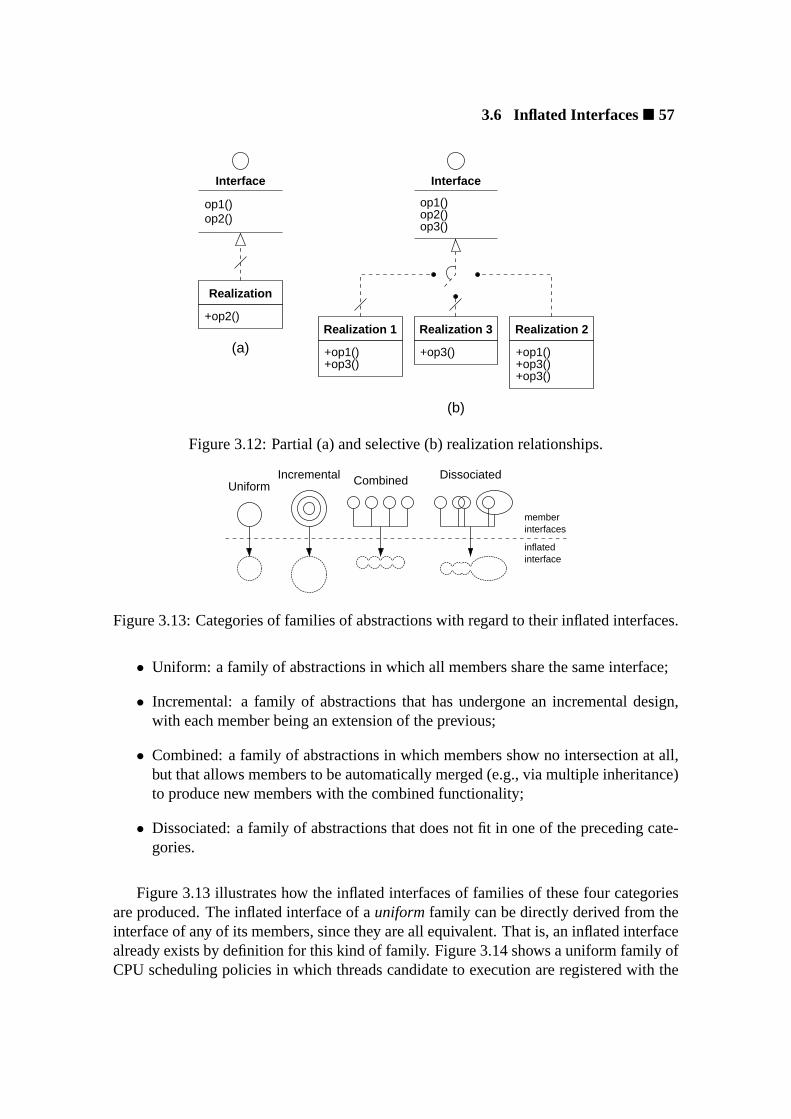
3.6 Inflated Interfaces� 57
Realization
+op2()Realization 1
+op3()+op1()
Realization 2
+op3()
+op1()+op3()
Realization 3
+op3()
Interface
op2()op1()
Interface
op1()
op3()op2()
(a)
(b)
Figure 3.12: Partial (a) and selective (b) realization relationships.
inflatedinterface
interfacesmember
DissociatedIncrementalUniform Combined
Figure 3.13: Categories of families of abstractions with regard to their inflated interfaces.
• Uniform: a family of abstractions in which all members share the same interface;
• Incremental: a family of abstractions that has undergone an incremental design,with each member being an extension of the previous;
• Combined: a family of abstractions in which members show no intersection at all,but that allows members to be automatically merged (e.g., via multiple inheritance)to produce new members with the combined functionality;
• Dissociated: a family of abstractions that does not fit in one of the preceding cate-gories.
Figure 3.13 illustrates how the inflated interfaces of families of these four categoriesare produced. The inflated interface of auniform family can be directly derived from theinterface of any of its members, since they are all equivalent. That is, an inflated interfacealready exists by definition for this kind of family. Figure 3.14 shows a uniform family ofCPU scheduling policies in which threads candidate to execution are registered with the

58� Chapter 3: Application-Oriented System Design
register()deregister()choose()
+choose()
+register()+deregister()
+choose()
+register()+deregister()
+choose()
+register()+deregister()
CPU_Scheduling_Policy
PRIORRFCFS
Figure 3.14: The inflated interface of a uniform family of CPU scheduling policies.
policy implementer by the thread manager. In order to select a new thread to occupy theCPU, the methodchoose is invoked. The information necessary to make a schedulingdecision is obtained directly from the registered threads by invoking appropriate methods,thus enabling a uniform interface for the policy implementers. If policies are allowed tobe changed at run-time, then the family should be implemented using polymorphism,making changes transparent to the thread manager. In fact, uniform families are usuallypolymorphic, since a common interface for the different types defined by each memberabstraction already exists.
A family of the incrementalcategory has its inflated interface derived from the mem-ber with the broadest interface, which encompasses all other members. An example ofthis kind of family is presented in figure 3.15. Each member of this family of thread ab-stractions adds functionality to the family by defining new operations. Operations withthe same signature also have the same semantics for all family members. MemberPri-ority is the most comprehensive one in the example, thus characterizing the inflatedinterface of the family.
The inflated interface of acombinedfamily can be produced by merging the individualinterfaces of all family members. This is the most flexible family organization in whatconcerns configurability, since it enables an eventual binding tool to perform arbitrarycombinations of family members in order to match the required inflated interface subsets.Nonetheless, this kind of family is extremely difficult to model, since each member hasto be designed considering the consequences of arbitrarily combining it with all othermembers. During the design of EPOS, the prototype system developed to validate theconcepts and techniques of application-oriented system design, no families of this typehave been identified.
The inflated interfaces of the former three categories, when designated by an applica-
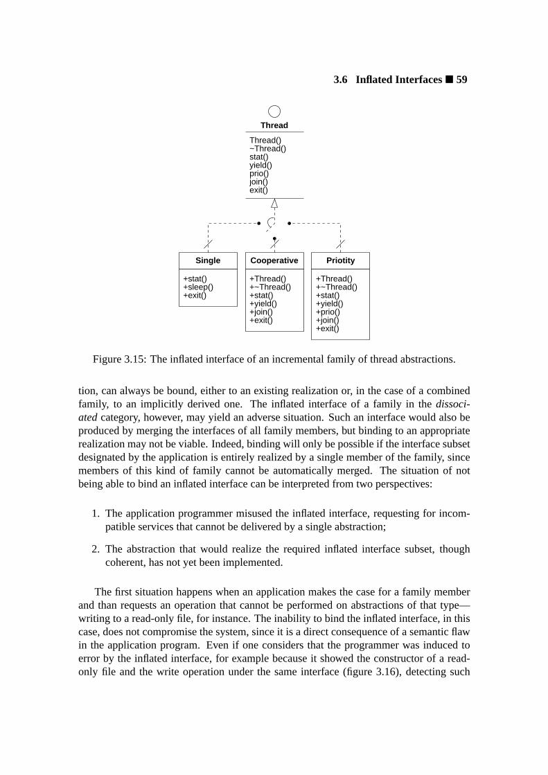
3.6 Inflated Interfaces� 59
+stat()+~Thread()+Thread()
+exit()+join()+prio()+yield()
+~Thread()+stat()
+Thread()
+yield()+join()+exit()
+stat()+sleep()+exit()
~Thread()Thread()
stat()yield()prio()join()exit()
Single Cooperative Priotity
Thread
Figure 3.15: The inflated interface of an incremental family of thread abstractions.
tion, can always be bound, either to an existing realization or, in the case of a combinedfamily, to an implicitly derived one. The inflated interface of a family in thedissoci-atedcategory, however, may yield an adverse situation. Such an interface would also beproduced by merging the interfaces of all family members, but binding to an appropriaterealization may not be viable. Indeed, binding will only be possible if the interface subsetdesignated by the application is entirely realized by a single member of the family, sincemembers of this kind of family cannot be automatically merged. The situation of notbeing able to bind an inflated interface can be interpreted from two perspectives:
1. The application programmer misused the inflated interface, requesting for incom-patible services that cannot be delivered by a single abstraction;
2. The abstraction that would realize the required inflated interface subset, thoughcoherent, has not yet been implemented.
The first situation happens when an application makes the case for a family memberand than requests an operation that cannot be performed on abstractions of that type—writing to a read-only file, for instance. The inability to bind the inflated interface, in thiscase, does not compromise the system, since it is a direct consequence of a semantic flawin the application program. Even if one considers that the programmer was induced toerror by the inflated interface, for example because it showed the constructor of a read-only file and the write operation under the same interface (figure 3.16), detecting such

60� Chapter 3: Application-Oriented System Design
+File()+~File()+read()
Read−Only Exclusive Shared
+File()+~File()
+write()+read()
+lock()+unlock()
+File()+~File()
+write()+read()
File(SH)~File()
write()read()
lock()unlock()
File(EX)File(RO)
File
Figure 3.16: The inflated interface of a dissociated family of file abstractions.
an error during system configuration is an advance in regard to ordinary systems, whichusually only detect this kind of error at run-time4.
The second case, however, exposes a controversial aspect of inflated interfaces: an ap-plication programmer, after having been invited to write an application in terms of inflatedinterfaces, may be required to modify it because a needed (and announced) componentis not available. This situation can be observed in the family of I/O buses depicted infigure 3.17. If an application invokes the methodscan on an object of typeISA , it im-plicitly requests for a realization that does not (yet) exist. However, scanning an ISAbus is a logically correct operation that could be implemented either by theISA memberitself or by a newPlug_and_Play_ISA member. Situations like this have to be takenin consideration during system design so as to decide, together with users, whether theuse of inflated interfaces for dissociated families is adequate or not.
Nevertheless, incidents that require applications to be modified will be more frequentin the early stages of system development, when many conceived abstractions have not yetbeen implemented, fading away with time. Furthermore, when such an incident happens,the operating system developers get a precise description of the missing component, whatcan considerably accelerate the development of the system as a whole. After all, this isnot a peculiarity of application-oriented system design: the same problem would occur ina family-based design and in a pure object-oriented design. It is intrinsic to giving a set
4The POSIX system callopen can be invoked to create a read-only file and nothing prevents the systemcall write to be invoked on the same file, resulting in a run-time error.

3.7 Reusable System Architectures� 61
+init()+reset() +reset()
+scan()
+init() +init()+reset()+scan()
PCMCIAPCIISA
reset()scan()
init()
IOBus
Figure 3.17: The inflated interface of a dissociated family of I/O buses.
of dissociated abstractions a common interface.
3.7 Reusable System Architectures
Along with the specification of abstraction families and scenario aspects, an application-oriented system design delivers specifications of reusable system architectures, whichdefine how abstractions can be arranged together in a functioning system. Reusable sys-tem architectures are usually defined considering the past experience with the buildingsystems of a certain class. After having developed some systems, or some versions of asystem, for a certain problem domain, developers begin to agree on how to implement theabstractions that build up the domain, how they interact with each other, with the envi-ronment, and with applications, and how the implied non-functional requirements can beaccomplished. Such an expertise can be captured in an architectural specification to bereused in upcoming systems.
Capturing reusable system architectures in a component-based system is fundamental,since a pile of components, by itself, is nothing but a pile of components. A component-based system is only achieved when components can be arranged together in an assem-blage of predictable behavior. In application-oriented system design, reusable architec-tures begin to be modeled yet during domain decomposition with the identification ofrelationships between families of abstractions. These relationships are enriched by sce-nario constraints during the specification of scenario aspects and serve as input for thisphase, which aims at producing a detailed specification of reusable system architecturesin the form of component frameworks.
An application-oriented component framework captures a reusable architecture byspecifying the families of abstractions that take part in a certain kind of system, as well

62� Chapter 3: Application-Oriented System Design
Framework
sockets for abstractions
inflated interfaces
scenario adapters
Figure 3.18: An application-oriented component framework.
as rules that guide their interaction. Systems produced by component frameworks, whencompared to arbitrary arrangements of components, are less prone to misbehavior, sinceonly compositions that have been predefined by system architects are allowed. Althoughcomponent frameworks are not the unique alternative to capture reusable architectures—among others,aspect programs, subjects, andcollaborationscould also be used for thispurpose—they fit perfectly with application-orientation’s notion of isolating scenario as-pects from abstractions by means of scenario adapters.
An application-oriented component framework could be defined as a collection ofinterrelated scenario adapters as shown in figure 3.18. Each scenario adapter would setup a “socket” for components of the corresponding family. Plugging components into theframework would be accomplished by binding the inflated interface of every used familyto the desired family member. The way scenario adapters are arranged in the frameworkwould define the basic architecture of resultant systems, while architectural elements thatdo not concern components could be hard-coded in the framework.
A component framework defined in terms of scenario adapters would also present ad-vantages concerningsystem-wide properties, which could be modeled as scenario aspectsto be enforced on components by the respective scenario adapters [SV98]. Moreover,a component framework of this kind does not require complex tools to manipulate thesource code of components in order to generate a system. After all, the representation ofa component framework as a socket board to which components can be plugged is wellunderstood and accepted by users.
Figure 3.19 shows a schematic representation of a component framework that embod-ies a plausible system architecture for the domain of high-performance communication inclusters of workstations used as example in section 3.3.1. It illustrates the relationshipsbetween the three families of abstractions modeled:Communication End-Point ,Communication Strategy , andNetwork . Firstly, it shows a mutual dependencybetween the families of strategies and end-points, i.e., by selecting a certain strategy, oneautomatically selects the corresponding end-point, and vice-versa. It also shows that a

3.7 Reusable System Architectures� 63
CommunicationFramework
scenario adapter
scenario adapter
scenario adapter
End−Point
Strategy
Network
scenario
Connection Mailbox
AM HandlerPort
ARM Seg. DSM Seg.
End−Points
DSMStream
Datagram AM
ARMRARMW
Strategies
Ethernet SCI
ATMMyrinet
Networks
aspects
Figure 3.19: A component framework for the domain of high-performance communica-tion.
network isusedby the members of the communication strategy family. The respectivesets of components are also shown to illustrate the “select-and-plug” organization of theframework.
An overview of the application-oriented system design method is presented in fig-ure 3.20. In summary, it is a multiparadigm design method that promotes the constructionof application-oriented operating systems by applying the process ofapplication-orienteddecompositionto engineer a domain as collection offamilies of reusable, scenario-independent abstractions. Scenario dependencies are modeled asscenario aspectsthatcan be enforced on abstractions by means ofscenario adapters. Families are made vis-ible to applications throughinflated interfaces, which export all members as though acomprehensive component was available. Reusable system architectures are captured incomponent frameworksdefined in terms of scenario adapters.

64� Chapter 3: Application-Oriented System Design
DomainProblem
Family
Infl. Inter.
MemberMember Member
Member
aspectfeatureconfig.
adapter
adapter
adapter
Scenario
aspect
aspect
AbstractionsFamilies of Frameworks
Figure 3.20: An overview of application-oriented system design.

3.8 Implementation Considerations� 65
3.8 Implementation Considerations
A system designed according to the directives of application-oriented system design canbe implemented using a variety of techniques. Anapplication-oriented system imple-mentation disciplineis not being proposed in this thesis because new techniques to im-plement components are being steadily introduced. Attempting to consolidate such animplementation discipline at this moment would certainly be precipitate. Nonetheless,several implementation techniques have been identified that can be useful to implementapplication-oriented system designs.
One aspect that is likely to be shared by application-oriented system implementationsis the programming language. Not because there is something inherent to the application-oriented system design method that depends on a programming language, but because ofthe very own nature of an operating system implementation, which demands full controlover the underlying hardware. The C programming language [KR84], also dubbed “theportable assembly”, supplies this demand and has been extensively used to implementoperating systems, however with known deficiencies in what concerns reusability andmaintainability [Bur95].
Application-oriented system design is a multiparadigm design method that has object-orientation on its core. Hence, designs produced with this method would be moresmoothly implemented in a multiparadigm language defined around object-orientation.As of today, the C++ programming language [Str86] is the non-experimental languagethat better satisfies these requisites: it exposes the bare hardware through its C subset,and it is a multiparadigm language centered on object-orientation. Therefore, C++ is themost probable choice to implement application-oriented operating systems and will beused in the examples throughout this section.
It is also important to keep in mind that abstractions in an application-oriented sys-tem design correspond to the components that are used to assemble a run-time supportsystem for a dedicated application, and that the decision of including a component in asystem configuration is taken before it is generated. Static configuration is a premise ofapplication-oriented system design that originates from its focus on dedicated computingsystems, so components are not loaded or replaced at run-time as in a reflective system(see section 3.1). This premise also calls for efficient implementations.
3.8.1 Abstractions
Abstractions in an application-oriented system design are modeled to be independentfrom execution scenario aspects and to be deployed independently of a specific frame-work. The construct that enables such a degree of independence is thescenario adapter,which engulfs an abstraction in order to mediate its interaction with a scenario dependentclient. In this way, abstractions can be designed and implemented without making anyconsideration about the scenario in which they will be used or how they will be placed
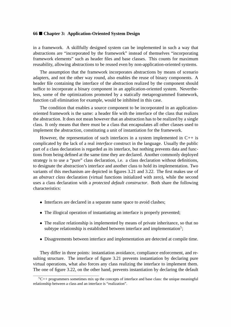
66� Chapter 3: Application-Oriented System Design
in a framework. A skillfully designed system can be implemented in such a way thatabstractions are “incorporated by the framework” instead of themselves “incorporatingframework elements” such as header files and base classes. This counts for maximumreusability, allowing abstractions to be reused even by non-application-oriented systems.
The assumption that the framework incorporates abstractions by means of scenarioadapters, and not the other way round, also enables the reuse of binary components. Aheader file containing the interface of the abstraction realized by the component shouldsuffice to incorporate a binary component in an application-oriented system. Neverthe-less, some of the optimizations promoted by a statically metaprogrammed framework,function call elimination for example, would be inhibited in this case.
The condition that enables a source component to be incorporated in an application-oriented framework is the same: a header file with the interface of the class that realizesthe abstraction. It does not mean however that an abstraction has to be realized by a singleclass. It only means that there must be a class that encapsulates all other classes used toimplement the abstraction, constituting a unit of instantiation for the framework.
However, the representation of such interfaces in a system implemented in C++ iscomplicated by the lack of a realinterfaceconstruct in the language. Usually the publicpart of a class declaration is regarded as its interface, but nothing prevents data and func-tions from being defined at the same time they are declared. Another commonly deployedstrategy is to use a “pure” class declaration, i.e. a class declaration without definitions,to designate the abstraction’s interface and another class to hold its implementation. Twovariants of this mechanism are depicted in figures 3.21 and 3.22. The first makes use ofan abstract classdeclaration (virtual functions initialized with zero), while the seconduses a class declaration with aprotected default constructor. Both share the followingcharacteristics:
• Interfaces are declared in a separate name space to avoid clashes;
• The illogical operation of instantiating an interface is properly prevented;
• The realize relationship is implemented by means of private inheritance, so that nosubtype relationship is established between interface and implementation5;
• Disagreements between interface and implementation are detected at compile time.
They differ in three points: instantiation avoidance, compliance enforcement, and re-sulting structure. The interface of figure 3.21 prevents instantiation by declaring purevirtual operations, what also forces any class realizing the interface to implement them.The one of figure 3.22, on the other hand, prevents instantiation by declaring the default
5C++ programmers sometimes mix up the concepts of interface and base class: the unique meaningfulrelationship between a class and an interface is “realization”.

3.8 Implementation Considerations� 67
namespace Interface{
class Abstraction{public :
virtual int operation1(void ) = 0;virtual void operation2(int ) = 0;
};}
class Abstraction : private Interface :: Abstraction{public :
int operation1(void );void operation2(int );
private :// Implementation declarations
};
Figure 3.21: An abstraction interface as a C++ pure abstract class declaration.
constructor protected and enforces compliance by declaring operations private, thus pro-ducing a compile-time error when a realization fails to adhere to the interface. The lattervariant has the advantage of avoiding the virtual function call mechanism. This mecha-nism is not likely to be eliminated for the interface that declares pure virtual operations,because syntactically it is identical to a base class, and there is no way to tell the compilerthe contrary.
Notwithstanding, both workarounds to specify abstraction interfaces in C++ have astrong negative effect on the corresponding implementations: specifying the realize re-lationship between interface and implementation through inheritance modifies the imple-mentation class. This happens as a side-effect of a language property that guarantees twoobjects never to be allocated the same address in memory, what is achieved by associatinga size greater than zero to all classes, abstract ones that cannot be instantiated and do nothave data members inclusive.
Therefore, asking forsizeof(Interface::Abstraction) yields a numbergreater than zero andsizeof(Abstraction) a number that corresponds to the ef-fective size of an instance ofAbstraction plus the minimum size allocated to theinterface. This may be insignificant for many abstractions, but would have disastrous con-sequences for a system-level abstraction that is precisely mapped across different storageunits (main memory and memory on a PCI device for instance). Hence, not represent-ing realize relationships at all is sometimes a better alternative for C++ implementations.The extra interface classes are thus restricted to document abstractions for users, while thepublic portion of the declaration of implementation classes assume the role of interfaces.

68� Chapter 3: Application-Oriented System Design
namespace Interface{
class Abstraction{protected :
Abstraction () {}
private :int operation1(void );void operation2(int );
};}
class Abstraction : private Interface :: Abstraction{public :
int operation1(void );void operation2(int );
private :// Implementation declarations
};
Figure 3.22: An abstraction interface as a C++ class declaration with a protected defaultconstructor.
In this way, problems with objects being shifted in memory are avoided.
Another reason not to represent realize relationships concerns constructors. As dis-cussed in section 3.4, declaring constructors in interfaces may be convenient to representdifferent initialization semantics for an abstraction. However, since C++ lacks an inter-face construct, expressing a constructor in one of the interfaces described above wouldforce the implementation class to forward arguments to the interface, completely degen-erating the notion of interface.
The common package of a family of abstractions is also ultimately delivered by a sin-gle class that is incorporated, directly or indirectly, by all its members. The most typicalway to incorporate the common package in an abstraction is through subclassing (privateinheritance), so that members do not become a subtype of it. Care must also be takento avoid the replication of the common package throughout the family. A member thatderives from another that already has the common package does not need to incorporate itagain, and a member that derives from multiple others expect these to have incorporatedthe common package using virtual inheritance.
Concerning the implementation of abstractions in families, one has firstly to considerthe category in which the family falls: uniform, incremental, combined, or dissociated.An example ofuniform family of abstractions is depicted in figure 3.23. Since uniform

3.8 Implementation Considerations� 69
class Common{protected :
Common() {}
// Family commonalities};
class Member_A: protected Common{public :
virtual ~Member_A();virtual int operation1(void );virtual void operation2(int i );
private :// Implementation declarations
};
class Member_B: public Member_A{public :
void operation2(int i );
private :// Implementation declarations
};
Figure 3.23: An example of uniform family of abstractions implemented in C++.
families are usually polymorphic [section 3.6], this example uses virtual functions. Thecommonalities of this family are gathered in classCommon, which is incorporated bythe family’s basic abstractionMember_A (base class) via protected inheritance (no sub-typing). Member_B specializes the family’s basic abstraction, inheritingCommonandoverriding its operations at convenience.
Figure 3.24 illustrates the case for incremental families. Every new member of thiskind of family adds functionality to a basic abstraction (Member_A in the example), oftendeclaring new operations (likeoperation2 in Member_B). Since the basic abstractionusually does not bear an interface capable of representing all abstractions in the family,polymorphism is mostly avoided. As with a uniform family, commonalities are incor-porated by the basic abstraction and are inherit by other members. SinceMember_BextendsMember_A, it can also be claimed forMember_ABresponsibilities.
An example of dissociated family of abstractions is presented in figure 3.25. Theunique syntactic aspect shared by the members of a dissociated family is its commonpackage (classCommonin the example), which is individually incorporated by each fam-

70� Chapter 3: Application-Oriented System Design
class Common{protected :
Common() {}
// Family commonalities};
class Member_A: protected Common{public :
int operation1(void );
private :// Implementation declarations
};
class Member_B: public Member_A{public :
void operation2(int i );
private :// Implementation declarations
};
typedef Member_B Member_AB;
Figure 3.24: An example of incremental family of abstractions implemented in C++.
ily member. The dissociated members of this family implement and export operations indetriment of each other (Member_Bknows nothing aboutoperation1 ). Note that thisdoes not rupture with the concept of family, since members can still be strongly semanti-cally connected (see discussion about inflated interface binding in section 3.6).
Figure 3.26 presents a combined family of abstractions. At first glance it evokes adissociated family, however, members of this kind of family can be arbitrarily combinedin order to obtain an abstraction with the corresponding functionality.Member_AB inthe figure illustrates the case. Nevertheless, these combinations are easier to assure struc-turally than semantically. In respect to structure, they are enabled by having a defaultconstructor in each member and deploying virtual inheritance to reuseCommon. Re-garding semantics, however, there is no simple strategy that can be applied to assure thecorrectness of such arbitrary compositions.
Combined and dissociated families are seldom polymorphic, since the discrepanciesbetween the types of their members are difficult to conciliate. This fact is usually evi-dent already at early stages of a family design; however, some programmers familiarized
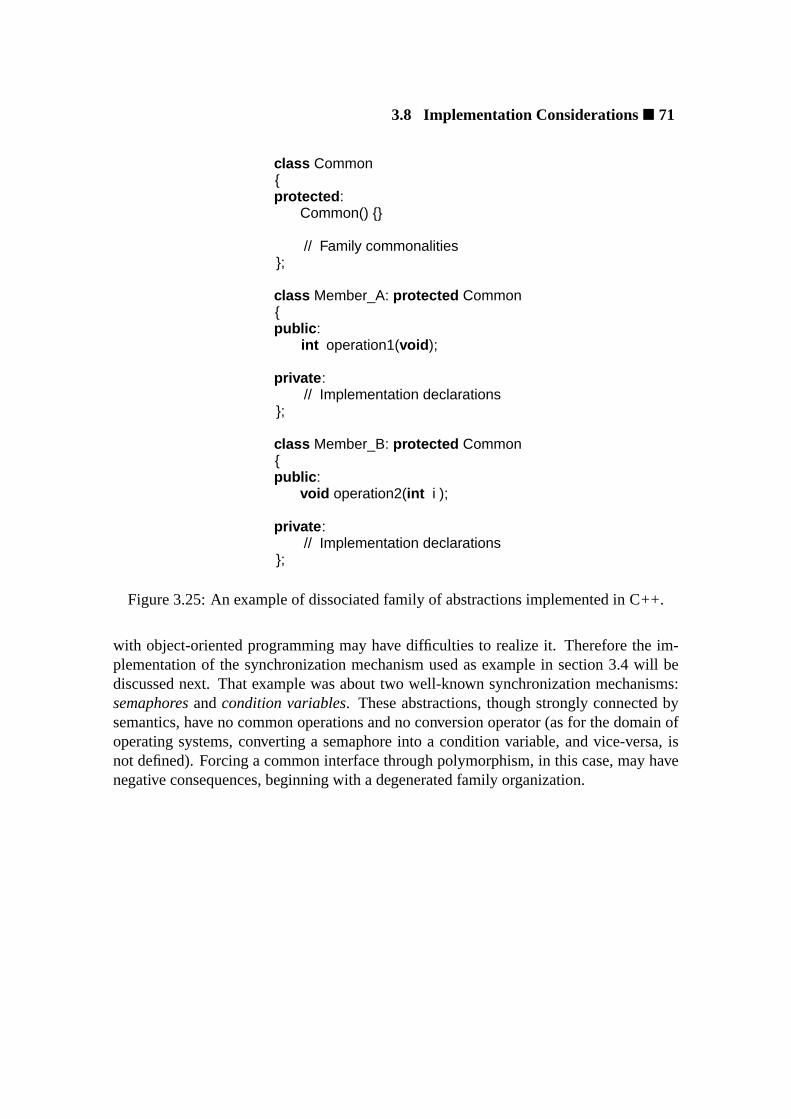
3.8 Implementation Considerations� 71
class Common{protected :
Common() {}
// Family commonalities};
class Member_A: protected Common{public :
int operation1(void );
private :// Implementation declarations
};
class Member_B: protected Common{public :
void operation2(int i );
private :// Implementation declarations
};
Figure 3.25: An example of dissociated family of abstractions implemented in C++.
with object-oriented programming may have difficulties to realize it. Therefore the im-plementation of the synchronization mechanism used as example in section 3.4 will bediscussed next. That example was about two well-known synchronization mechanisms:semaphoresandcondition variables. These abstractions, though strongly connected bysemantics, have no common operations and no conversion operator (as for the domain ofoperating systems, converting a semaphore into a condition variable, and vice-versa, isnot defined). Forcing a common interface through polymorphism, in this case, may havenegative consequences, beginning with a degenerated family organization.

72� Chapter 3: Application-Oriented System Design
class Common{protected :
Common() {}
// Family commonalities};
class Member_A: virtual protected Common{public :
Member_A();int operation1(void );
private :// Implementation declarations
};
class Member_B: virtual protected Common{public :
Member_B();void operation2(int i );
private :// Implementation declarations
};
class Member_AB: public Member_A, public Member_B {};
Figure 3.26: An example of combined family of abstractions implemented in C++.

3.8 Implementation Considerations� 73
Polymorphism degenerates the organization of the synchronizer family because itforces unreal relationships between its members. There are four possible organizationsfor a polymorphic synchronizer:
a) Member semaphore becomes the basic abstraction, with condition variable as itssubtype;
b) The other way round, i.e. condition variable becomes the basic abstraction, andsemaphore its subtype;
c) An extra abstract class gathering the operations of semaphore and condition variablebuilds a basic type for the family;
d) An extra empty abstract class serves as supertype for semaphore and condition vari-able.
Alternatives (a) and (b) clearly break the correspondence of abstractions with the prob-lem domain. Alternative (c) is depicted in figure 3.27. In order to build a common in-terface, classSynchronizer has to declare all operations in the family. However,because there is not a single operation that is common to all members, it cannot declarepure virtual methods, having to resort to a protected constructor as well as to ordinarymethod declarations. This is probably the worst of the four solutions, since the operationsdeclared inSynchronizer must also be defined and would be suitable to be invokedby applications. That is, an application would get no compiler error for invoking oper-ation broadcast on aSemaphore if this was made trough aSynchronizer * .Alternative (d) does not add much more value than avoid * . Therefore, none of thesealternatives seems to be of any help for users.

74� Chapter 3: Application-Oriented System Design
class Synchronizer{protected :
Synchronizer();
public :virtual ~Synchronizer();virtual void p();virtual void v ();virtual void wait ();virtual void signal ();virtual void broadcast();
};
class Semaphore: public Synchronizer{public :
Semaphore(int value = 1);~Semaphore();void p();void v ();
private :// Implementation declarations
};
class Condition: public Synchronizer{public :
Condition();~Condition();void wait ();void signal ();void broadcast();
private :// Implementation declarations
};
Figure 3.27: A polymorphic family of synchronization abstractions implemented in C++.

3.8 Implementation Considerations� 75
3.8.2 Inflated Interfaces
The inflated interface of a family differs considerably from those of its member abstrac-tions, for it is subject to thepartial andselectiverealize relationships introduced in sec-tion 3.6. These relationships between inflated interfaces and family members are ulti-mately what enable an application-oriented operating system to be tailored to an appli-cation. Nevertheless, they add to the problematic of representing interfaces. The partialrealize relationship to which these interfaces are subject allows a class to realize just aportion of an inflated interface, excluding the representation of interfaces by means ofconstructs that enforce integral compliance. At the same time, the selective realize rela-tionship calls for a binding mechanism that can be controlled externally and that assuresa single realization is bound to an interface at a time.
These conditions lead inflated interfaces to be represented in C++ by means of ordi-nary class declarations similar to the one illustrated in figure 3.28. The interface of thisincremental family, represented by classFamily , gathers all operations and constructorsdefined throughout the family. An application (last program fragment in the figure) couldbe written in terms ofFamily , thus postponing the choice of a family member, or dele-gating it to a tool. In this simple example,Member_B would be the choice, since it is theunique member that implementsoperation2 .
When the inflated interface is unbound, classFamily is exported from theInter-face name space to the name space where realizations are declared, allowing applicationto be compiled. When one realization is selected,Family is again hidden in name spaceInterface , and the selected realization is renamedFamily . Both operations can beaccomplished in C++ through the type definition mechanism (typedef ). If consideredconvenient by the designer, the binding of inflated interfaces can be centralized in a singleconfiguration table, which could look like this:
// Forward declarationsclass Member_A;class Member_B;namespace Interface { class Family; }// Bindings# if FAMILY == MEMBER_Atypedef Member_A Family;# elif FAMILY == MEMBER_Btypedef Member_B Family;#elsetypedef Interface :: Family Family;# endif
This is certainly a very simple example, but it serves to demonstrate the flexibility de-livered by the inflated interface mechanism. Application programs can be written in termsof inflated interfaces, which are later bound to specific realizations either manually by the
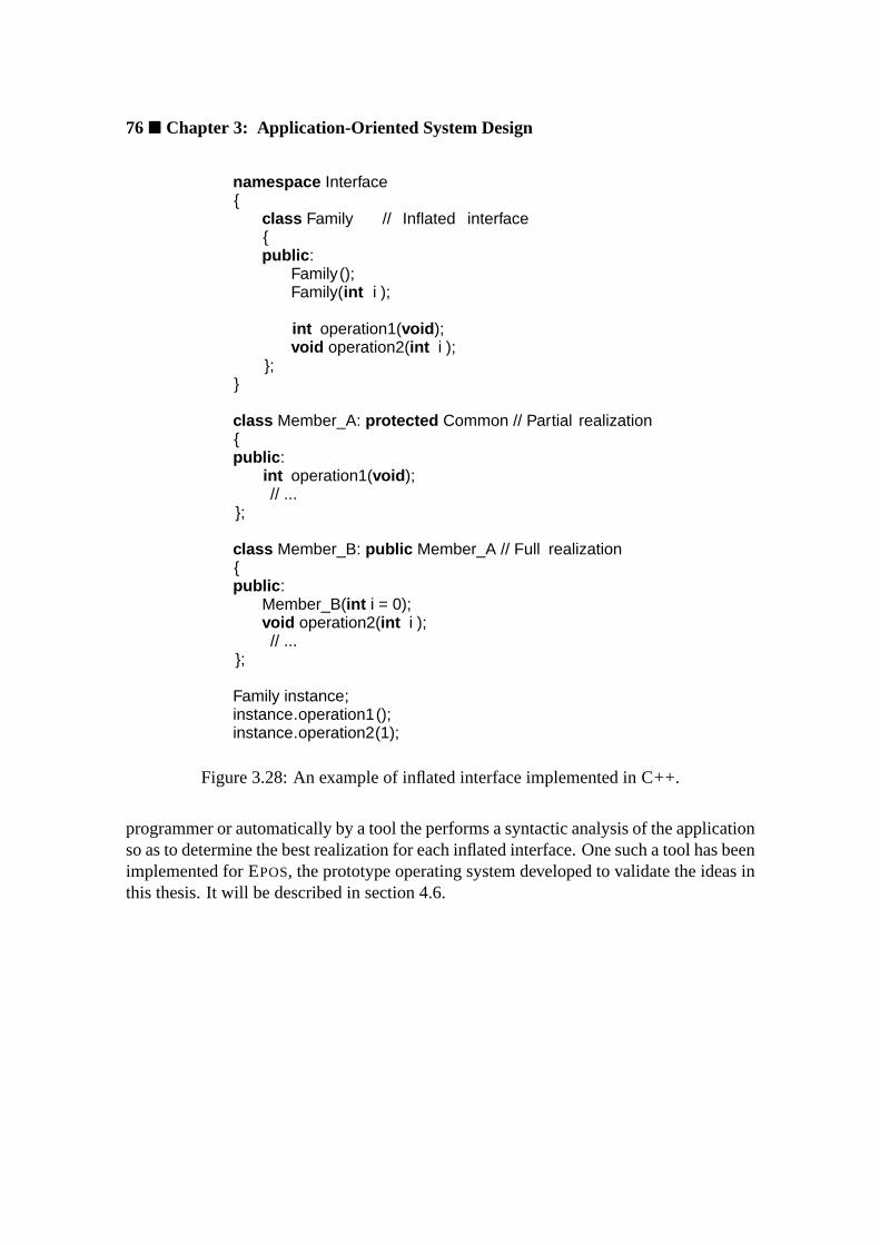
76� Chapter 3: Application-Oriented System Design
namespace Interface{
class Family // Inflated interface{public :
Family();Family(int i );
int operation1(void );void operation2(int i );
};}
class Member_A: protected Common // Partial realization{public :
int operation1(void );// ...
};
class Member_B: public Member_A // Full realization{public :
Member_B(int i = 0);void operation2(int i );// ...
};
Family instance;instance.operation1();instance.operation2(1);
Figure 3.28: An example of inflated interface implemented in C++.
programmer or automatically by a tool the performs a syntactic analysis of the applicationso as to determine the best realization for each inflated interface. One such a tool has beenimplemented for EPOS, the prototype operating system developed to validate the ideas inthis thesis. It will be described in section 4.6.

3.8 Implementation Considerations� 77
3.8.3 Scenario Aspects
Execution scenario aspects identified and isolated during the process of application-oriented system design can be implemented observing the same considerations statedabout abstractions. Indeed, scenario aspects are usually also organized in families ac-cording to their commonalities. The inflated interface of these families is left unbounduntil the execution scenario for a certain application becomes evident. These aspectsare then grouped by ascenarioconstruct, and applied to abstractions through ascenarioadapter.
The implementation of a family of scenario aspects is illustrated in figure 3.29.When the scenario aspects in this family are applied to an abstraction, they confer itsoperations atomicity. This is accomplished by having the scenario adapter to invokelock and unlock operations so that the abstraction is trapped in a kind of moni-tor [Hoa74]. Thestatic versions oflock andunlock are used to provide atom-icity for class operations such as constructors6, destructors, and some built-in opera-tors. TheCoarse_Atomic aspect locks all abstractions with a single mutex, whileFine_Atomic utilizes an individual mutex for each abstraction.
Before being applied to abstractions, scenario aspects are grouped in ascenario, whichconstitutes the first construct defined in the scope of an application-oriented componentframework. While abstractions and execution scenario aspects are designed and imple-mented to be fully reusable independently of a specific framework, scenarios and sce-nario adapters are specific to frameworks. In general, the scenario construct incorporatesselected scenario aspects via aggregation (which can also be implemented in C++ usingsingle inheritance). If scenario aspects are smoothly applied to all abstractions, their in-clusion in the scenario can be controlled using simple conditional compilation techniques.
Nevertheless, generic programming techniques can be deployed to enable aspects tobe individually applied to abstractions. For instance thetraits concept used in the C++standard library [Str97]. Traits are parameterized classes whose static constant membersdescribe the properties (the traits) of a certain type. An example is shown in figure 3.30.The parameterized classScenario_Traits denotes the properties of abstractions withregard to execution scenarios. It can represent a pattern of properties that have to besupplied for each abstraction (private access control,Member_A in the figure), or it canitself represent default values for properties (public access control,Member_B in figure).The latter applies to any known type. If traits are used, the scenario construct shouldalso be implemented as a parameterized class that relies on theScenario_Traits todecide which aspects have to be applied to each abstraction.
Besides incorporating scenario aspects, a scenario construct usually also implementsoperations to establish the pre and post conditions required by the scenario for each inter-action between a client and a scenario-independent abstraction. These operations have to
6Providing atomicity for object creation requiresstatic_lock to be called from the scenario adapteroperator new andstatic_unlock from the scenario adapter constructor.

78� Chapter 3: Application-Oriented System Design
namespace Interface{
class Atomic{public :
void lock ();void unlock();static void static_lock ();static void static_unlock ();
};}
class Atomic_Common{protected :
Atomic_Common() {}
public :static void static_lock () { static_mutex.lock (); }static void static_unlock () { static_mutex.unlock (); }
private :static Mutex static_mutex;
};
class Coarse_Atomic: protected Atomic_Common{public :
void lock () { Atomic_Common::static_lock(); }void unlock () { Atomic_Common::static_unlock(); }static void static_lock () { Atomic_Common::static_lock(); }static void static_unlock () { Atomic_Common::static_unlock(); }
};
class Fine_Atomic: protected Atomic_Common{public :
void lock () { mutex.lock (); }void unlock () { mutex.unlock (); }static void static_lock () { Atomic_Common::static_lock(); }static void static_unlock () { Atomic_Common::static_unlock(); }
private :Mutex mutex;
};
Figure 3.29: A C++ example of scenario aspect.

3.8 Implementation Considerations� 79
template <class T>class Scenario_Traits{// public : or private :
// ...static const bool is_atomic = false ;static const bool is_shared = false ;static const bool is_protected = false ;// ...
};
template <>class Scenario_Traits<Member_A>{public :
// ...static const bool is_atomic = true ;static const bool is_shared = false ;static const bool is_protected = false ;// ...
};
template <>class Scenario_Traits<Member_B>:
public Scenario_Traits<void >{public :
static const bool is_atomic = true ;};
Figure 3.30: Traits of abstractions with regard to scenario aspects.
consider arbitrary combinations of scenario aspects, enforcing specializations when con-flicts arise. A definitive characterization of a scenario, however, can only be formulatedin the context of a specific framework.
Scenario adapters, which ultimately apply scenario aspects to abstractions, are alsohighly depended from the framework in which they are defined. Nevertheless, adapt-ing an abstraction almost always implies in “wrapping” its operations so that they areexecuted enclosed within a pair of primitives withenter and leavescenario semantics.Several mechanisms to wrap objects and operations have been proposed for the C++ pro-gramming language. The direct ancestor of C++, CWITH CLASSES[Str94], allowed twospecial functions, namelycall andreturn , to be defined for a class. These functionswere implicitly called respectively before and after member functions of that class.
Tiemann [Tie88] proposed a language extension called “wrappers” that can be usedto wrap the invocations of member functions of a class. Such a wrapper is identified by

80� Chapter 3: Application-Oriented System Design
class A_Class{public :
int () A_Class(int (A_Class::∗ function)( int ), int i ) {enter ();int ret = ( this−>∗function)(i );leave ();return ret ;
}
int operation( int );}
A_Class∗ p = new A_Class;p−>operation(1); // p−>()A_Class(&A_Class::operation, 1);
Figure 3.31: Tiemann’s proposal to wrap member functions in C++.
a pair of parentheses in front of the name of the class whose functions are to be wrapped(figure 3.31). A particularly interesting property of this mechanism is that it has access toarguments and to the return value of the function being wrapped, being useful to imple-mentRemote Procedure Callmechanisms [BN84].
Unfortunately, none of these proposals has been incorporated by the standardized ver-sion of the language (ISO 14882). Nonetheless, some programming “tricks” can be usedto overcome this language deficiency. Stroustrup [Str00] summarizes them in a parame-terized class that wraps the methods of its argument class. This mechanism is depictedin figure 3.32. Theenter primitive is called by the overloadedoperator-> , whichreturns a temporary object of typeCall_Proxy<T> containing the pointer to the ob-ject on which the operation will be invoked. Theleave primitive is called when thistemporary object is destroyed. Actually no extra objects are created at all, since thismetaprogrammed mechanism is completely resolved by the compiler into something like(enter(); operation(); leave();) . Another advantage of this mechanismis that it is not intrusive, i.e. it does not require modifications on the classes to which itapplies. Its main disadvantage is thatenter andleave do not have access to argumentssupplied to the wrapped function.

3.8 Implementation Considerations� 81
template <class T>class Call_Proxy{public :
Call_Proxy(T∗ pp) : p(pp ) {}~Call_Proxy () { leave (); }T∗ operator −>() { return p; }
private :T∗ p;
};
template <class T>class Wrap{public :
Wrap(T∗ pp) : p(pp) {}Call_Proxy<T> operator −>()
{ enter (); return Call_Proxy<T>(p); }
private :T∗ p;
};
class A_Class{public :
int operation1();int operation2(int );
};
Wrap<A_Class> obj(new A_Class);obj−>operation1();obj−>operation2(2);
Figure 3.32: Stroustrup’s proposal to wrap member functions in C++.

82� Chapter 3: Application-Oriented System Design
template <class OBJ, class RET> // no argumentsRET invoke(OBJ∗ obj, RET(OBJ:: ∗ func)()){ enter (); RET r = (obj−>∗func)(); leave (); return r ; }
template <class OBJ> // no arguments, no returnvoid invoke(OBJ∗ obj, void (OBJ:: ∗ func )()){ enter (); ( obj−>∗func)(); leave (); }
template <class OBJ, class RET, class ARG> // one argumentRET invoke(OBJ∗ obj, RET(OBJ:: ∗ func)(ARG), ARG arg){ enter (); RET r = (obj−>∗func)(arg); leave (); return r ; }
template <class OBJ, class ARG> // one argument, no returnvoid invoke(OBJ∗ obj, void (OBJ:: ∗ func)(ARG), ARG arg){ enter (); ( obj−>∗func)(arg); leave (); }
class A_Class{public :
int operation1();int operation2(int i );
};
A_Class∗ obj = new A_Class;invoke(obj, &A_Class::operation1);invoke(obj, &A_Class::operation2, 1);
Figure 3.33: An alternative to wrap member functions in C++.
A solution to the member function wrapping problem that allows arguments to beaccessed like in the Tiemann’s proposal can be devised using function templates. Theprogram fragments in figure 3.33 illustrate how. The first version of function templateinvoke takes two parameters: the type of the object whose functions are being wrapped,and the return type of the function being invoked. It then “sandwiches” the functionbetweenenter andleave , taking care of the return value. Function templateinvokeis specialized for functions that do not return any value (void function() ) in thesecond fragment, and is successively overloaded to wrap functions that take a growingnumber of arguments (only the first overloading is shown in figure). In order to wrapan operation, one has to invoke it using theinvoke function template, which has plainaccess to its arguments and return value. The whole mechanism can be made transparentby a wrapper class, though with considerable effort, since every operation defined for thewrapped class has to be represented in the wrapper.

3.9 Summary� 83
3.9 Summary
Historically, applications have been adapted to the operating system, adhering to stan-dardized application program interfaces that covey uncountable useless services (for eachindividual application), and yet fail to deliver much of what is necessary. An application-oriented operating system ruptures with this notion, implementing services that emanatefrom application requirements and delivering them as a set of configurable componentsthat can be assembled to produce application-tailored system instances.
Such application-oriented operating systems can be constructed deploying theapplication-oriented system design method to engineer the envisioned domain. In thisway, the domain is decomposed in abstractions that model application-specific perspec-tives of each entity. These abstractions are gathered in families according to what theyhave in common, with variability analysis being deployed to identify subsequent mem-bers of each family. During this process, variations that belong to the essence of abstrac-tions are separated from those that emanate from execution scenarios, the former shapingfamily members, and the latter yielding scenario aspects. This separation improves onreusability, for scenario-independent abstractions can be reused in a larger variety of sce-narios.
Maintainability in a component-based system is mainly a function of the number ofcomponents and of the complexity of each component. The separation of abstractionsand scenario aspects improves both factors. Scenario-independent abstractions are lesscomplex than their scenario-dependent counterparts, for they do not need to deal with en-vironmental particularities. At the same time, the number of modeled software artifacts isreduced, since most scenario aspects apply to several abstractions (some even apply to allabstractions). Furthermore, not all of the variability observed in a family of abstractionsyields family members. Some designate optional features that concern to several mem-bers at once. Instead of specializing each abstraction to produce versions that includesuch features, application-oriented domain decomposition suggests generic implementa-tions of these configurable features to be modeled as constructs that can be reused byexisting family members when the corresponding feature is required. An explosion ofabstraction specializations is so avoided.
Still during domain decomposition, ad-hoc relationships between families of abstrac-tions are exploited to model reusable software architectures. Such architectural specifi-cations designate valid combinations of abstractions and scenario aspects that are subse-quently materialized as component frameworks. In this way, application-oriented systemdesign advances in one of the most contentious aspects of component-based software en-gineering: how to tell valid composites form invalid ones.
Abstractions modeled during domain decomposition originate the software compo-nents of an application-oriented operating system on 1-to-1 relation. They are deliveredto users as abstract data types, with interfaces that clearly identify their responsibilities.Scenario aspects are maintained separately, being combined at user’s wish to shape the

84� Chapter 3: Application-Oriented System Design
execution scenario for a certain composite. They are applied to abstractions by means ofscenario adapters, which act as agents to mediate the interaction of scenario-dependentclients with scenario-independent abstractions.
In order to enable applications to deal with families of abstractions as they were singleentities, an inflated interface is delivered for each family in an application-oriented systemdesign. Such an interface exports a family as though a “super” component was availablethat implements all responsibilities assigned to the family. The choice of specific familymembers can thus be postponed or even delegate to a configuration tool. Such a toolwould analyze the applications to determine which subsets of each inflated interface havebeen used, binding them to the most appropriate realization available.
The configurable system architectures modeled during domain analysis are deliveredto users as component frameworks defined in terms of scenario adapters. Each scenarioadapter constitutes a placeholder for an abstraction, pre-establishing relevant relation-ships. Abstractions are plugged to the framework via the inflated interface binging mech-anism, which is also used to select scenario aspects.
An application-oriented operating system designed according to the directives ofapplication-oriented system design can be implemented using a variety of techniques.As of today, it is probable that the C++ will the choice for most implementations, be-cause it is one of the few programming languages that completely expose the underlyinghardware, an essential condition for an operating system implementation. Furthermore,C++ supports multiple programming paradigms, including static metaprogramming, thatcan be combined to achieve efficient implementations.

Chapter 4
The EPOS System
This chapter describes EPOS, the experimental operating system developed in the scopeof this dissertation to validate the concepts and techniques introduced in chapter 3. Afteran introduction of historical facts and fundamentals, the application-oriented system de-sign of EPOSis presented, including the families of system abstractions, scenario aspects,and system architectures that result from the decomposition of the high-performance ded-icated computing domain. Subsequently a strategy to automatically configure the operat-ing system according to the needs of particular applications is presented.
4.1 A Bit of History
The EPOSsystem was born in 1997 at the Research Institute for Computer Architectureand Software Engineering (FIRST) of the German National Research Center for Informa-tion Technology (GMD) as a project to experiment with the concepts and mechanisms ofapplication-oriented system design. Indeed, EPOSand application-oriented system designcannot be disassociated, since both have been evolving together from the very beginningas the research substratum for this dissertation.
The acronym EPOS1 stands forEmbedded Parallel Operating System. It was coinedconsidering the main research goal established for the early system: to embed the op-erating system in a parallel application. The strategy followed to achieve this goal con-sisted in modeling the corresponding domain entities as a set of reusable and adaptablecomponents, and developing a mechanism to allow parallel applications to easily specify
1The German word “epos” means “epic” in English, and, although suggesting that EPOS is an epic—about an academic operating system (a Portuguese sailor) that had to traverse a sea of difficulties (ofstandardized application program interfaces), passing by Taprobana (the common-sense defined by UNIX
and Microsoft WINDOWS), to reach India (modern software engineering)—would be too pretentious, themetaphors about the epic “Os Lusiadas” [dC72] are left for the delight of readers (application program-mers).

86� Chapter 4: The EPOS System
constraints to guide the arrangement of these components in a functioning system. As thesystem evolved, it became clear that this strategy could be applied to a broader universe ofapplications. Concerning design and organization, EPOSis inherently tied with dedicatedcomputing and static configurability, but whether a platform is dedicated to an applicationtemporarily (like in traditional parallel systems) or permanently (like in most embeddedsystems) does not play a significant role. Hence,Embedded Parallel Operating Systemcan also be interpreted as a system that targets both embedded and parallel applications.
EPOSowes much of its philosophy to the PEACE system [SP94a], from which it in-herited the notion that “generic” and “optimal” are adjectives that cannot be simultane-ously applied to the same operating system, besides a rich perception of family-baseddesign. EPOSimplementation for the Intel iX86 architecture reuses some of the strategiesadopted in ABOELHA [FAPS96], a former research operating system developed by theauthor. However, the design of ABOELHA did not promote reuse, so these strategies hadto be completely remodeled for EPOS.
4.2 Fundamentals
EPOS was designed following the guidelines ofapplication-oriented system designde-scribed in chapter 3. Indeed, EPOS has been created to experiment with application-oriented system design, which in turn has been evolving to contemplate design issuesarisen by EPOS. Consequently, the design of EPOSis intrinsically application-oriented.
The domain envisioned by EPOS is that of high-performance dedicated computing,which comprises applications that, besides running with exclusivity on the respective plat-forms, require an efficient management of resources. It is important to notice that bothadjectives, dedicated and high-performance, can be interpreted subjectively. As explainedearlier in chapter 1, a dedicated system does not need to be permanently dedicated, it canalso be scheduled to serve diverse applications, each of which gaining absolute controlover the platform for a certain time. Similarly, a high-performance system does not needto be always associated to billions of floating point operations. In what concerns the op-erating system, a small, embedded application that demands the absolute majority of theresources available in the platform to accomplish its duties calls for a high-performanceoperating system just like a parallel application does.
Aiming at supporting applications in the high-performance dedicated computing do-main, EPOSwas designed pursuing the following goals:
• Functionality: EPOSshall deliver the functionality necessary to support the execu-tion of high-performance dedicated applications.
• Customizability: EPOSshall be highly customizable, so that system instances canbe tailored to specific applications; whenever possible, system tailoring shall suc-ceed automatically.

4.3 System Abstractions� 87
• Efficiency: EPOS shall make resources available to applications with the lowestpossible overhead, besides being itself thrifty.
The domain of high-performance dedicated computing aimed by EPOS is under con-stant evolution, steadily assimilating technological innovations. As a product of domainengineering, EPOShad to consider the dynamics of the envisioned domain, setting up anopen and continuous domain analysis process that allows new entities to be included in thedesign as they are incorporated by the domain. Families of abstractions were thoroughlymodeled, leaving room for upcoming members. Even the hypothesis of completely newfamilies being added to the system has been taken in consideration.
The extreme scalability implied by these goals could only be achieved with a metic-ulousseparation of concerns. As suggested by application-oriented system design, ab-stractions were modeled independently of each other, of execution scenario aspects, andof component frameworks. Consequently, EPOSabstractions can be extensively reusedin a variety of scenarios. Furthermore, the framework can be adjusted to accommodateforthcoming abstractions, or to build particular software architectures, without affectingexisting abstractions. In this way, EPOScould develop into an application-oriented oper-ating system.
For the forthcoming discussion of EPOS design, however, it is important to bear inmind that the ultimate goal of EPOSis the validation of application-oriented system designconcepts and techniques. Therefore, some complex domain entities were specified only tothe extent of corroborating application-oriented system design. Such entities would haveto be further refined in order to sustain an actual implementation.
4.3 System Abstractions
EPOS families of abstractions result from the application-oriented decomposition of thehigh-performance dedicated computing domain. Many of the entities in this domain thatconcern the operating system are conventions defined by computer scientists and systemdevelopers. Therefore, EPOSresorted to traditional operating system books (e.g. Tanen-baum [Tan92] and Silberschatz [SGP98]) as a reference to the operating system domainvocabulary. This decision helped to make EPOS user-friendlier, since its abstractionshave been named after the classic concepts they represent, giving many of them a self-explanatory character. Systems that assign ethereal names to abstractions impose extradifficulties to users, which first have to discover the name of abstractions they want touse.
Yet, many operating system abstractions stem from physical devices. These abstrac-tions are conventionally modeled considering the role physical devices play in the oper-ating system. However, as an application-oriented operating system, EPOSgives priorityto the role they play in application programs. For example, thetimer physical resource is

88� Chapter 4: The EPOS System
delivered as an abstraction capable of generating alarm events for applications, though itis internally reused as the operating system time-keeping device.
As proposed by application-oriented system design, EPOS abstractions have beenmodeled independently of execution scenario aspects and specific system architectures.Consequently, EPOSabstractions could reach a degree of reusability that allows, for in-stance, the same abstraction of theThread family to be deployed in a single- or multi-tasking environment, as part of aµ-kernel or completely embedded in an application. Theprotection barrier the eventually separates applications from each other and from the op-erating system is not modeled in the context of abstractions, but as an architectural aspectof EPOS framework. Furthermore, the separation of scenario aspects from abstractionsconsiderably reduced the number of components in EPOSrepository, whereas numerousscenario-specific specializations could be suppressed.
Figure 4.1 shows a top-level representation of EPOS families of abstractions. Fami-lies were organized in six large groups:memory management, process management, pro-cess coordination, inter-process communication, time management, andI/O management.Each one of these groups will be subsequently described in this section, while applicablescenario aspects will be described in the next section. Exception is made to private orspecialized scenario aspects, which are described in the scope of the family (or abstrac-tion) to which they regard. Non-portable abstractions, such asnodeandprocessor, weremodeled in EPOSashardware mediators. These abstractions will be separately describedin section 4.5.2.2.
The inflated interface of each family of abstractions will not be explicitly presented,since this would bring little contribution to the reasoning on EPOS design in compari-son to explosion of details it would trigger. Nevertheless, the category of each family ofabstractions—whether uniform, incremental, combined, or dissociated—will be identi-fied, thus revealing how their inflated interfaces have been specified.
Abstractions
cationCommuni−
Memory
Process
nationCoordi−
Time
I/O
Figure 4.1: Groups of families of abstraction in EPOS.

4.3 System Abstractions� 89
4.3.1 Memory Management
Memory management in EPOS is accomplished by the families of abstractions shown infigure 4.2. The main memory available in the system is delivered to applications throughthe concept of memory segment realized by theSegment family. In order to be manipu-lated, a segment must first be attached to the address space of a process, which is realizedby the Address_Space family. Besides supporting this logical concept, the familyof address spaces is the one that ultimately implements a memory management policyfor the system, since it controls the allocation and mapping of the physical memory thateffectively makes up a memory segment.
In the context of application-oriented operating systems,virtual memoryis not an au-tonomous domain entity, but a workaround to enable the execution of applications withmemory requirements that exceed the available physical memory. That is, applications donot directly demand virtual memory, they demand memory. However, currently availablevirtual memory mechanisms are mostly inadequate to support applications in the domainof high-performance dedicated computing, firstly because many dedicated systems do notcount on a secondary storage to extend main memory, but also because such mechanismsdo not sustain high-performance. Therefore, no virtual memory strategy has been mod-eled for EPOSat this time.
4.3.1.1 Memory Segments
A memory segment is nothing but a chunk of main memory that can be used by applica-tions to store arbitrary code and data. The physical memory corresponding to a memorysegment is managed by the family of address spaces, thus keeping theSegment familyindependent of a memory management policy. Figure 4.3 shows EPOSfamily of memorysegments, which was designed in an incremental fashion. The common aspects of thefamily are encapsulated in a package that is reused by memberStatic , which is in turnextended by memberDynamic . The former is responsible for memory segments thatcannot be resized nor can have their properties modified after having been attached, whilethe latter allows for these operations.
Segment
Memory AddressSpace
Figure 4.2: Families of abstractions concerning memory management in EPOS.

90� Chapter 4: The EPOS System
These abstractions could only be modeled as an incremental family because the effec-tive allocation and mapping of physical memory to build a segment is carried out by thefamily of address spaces. Otherwise, differences in allocation policy would have madethis design impractical. Furthermore, the family was reduced to only two members be-cause sharing and protection were model as scenario aspects2. The Shared scenarioaspect profits from the memory mapping capabilities of theAddress_Space family tosupport the sharing of segments among processes, while theProtected aspect uses themapping modes provided by that family to protect segments against detrimental access.
Both abstractions in this family are mutually exclusive, since their dependencies onthe family of address spaces, itself mutually exclusive, cannot be accommodated simul-taneously. In order to allow resizing, memberDynamic requires a non-contiguous map-ping of physical memory, which is only provided by thePaged member of theAd-dress_Space family. MemberStatic has no requirements in this regard and is ableto operate properly with any kind of address space.
Dynamic
Static
Segment
Paged_AS
Address_Spaceprotected
shared
Figure 4.3: EPOSfamily of memory segments.
4.3.1.2 Address Spaces
The address space of a process corresponds to the range of memory addresses it can ac-cess. In order to support multitasking, most hardware architectures include aMemoryManagement Unit(MMU) that enables the separation of logical and physical addressspaces. A process is thus said to have a logical address space, which is mapped into thephysical memory address space. The MMU supports a non-contiguous mapping betweenthese address spaces, enabling a rational use of memory by multiple processes. Never-theless, many dedicated applications are carried out by a single process (on each node)and will not benefit from this mechanism. Moreover, some dedicated applications are ex-ecuted on platforms that do not feature a MMU. Therefore, an address space abstractionfor the dedicated computing domain must consider both perspectives: with and withoutlogical address mapping.
2The Shared andProtected scenario aspects modeled here are specializations of global scenarioaspects described in section 4.4.

4.3 System Abstractions� 91
The concept of address space is realized in EPOSby the dissociated family of mutuallyexclusive abstractions shown in figure 4.4. These abstractions are not intended to bedirectly used by application programmers. They are implicitly invoked as a result of thememory and process management policies in force. TheFlat member is used whena single process (possibly multithreaded) executes alone in the system. It implementsa policy that pre-allocates all the memory available in the system to this single processin a contiguous way, dispensing with a MMU and allowing for an efficient application-level memory allocator (malloc ). This allocator would still have to keep track of thestretches of memory currently being used, but would no longer need to perform physicalmemory allocation and mapping. The contiguous property of theFlat address spacealso brings an important advantage to processes that perform user-level I/O: since logicaland physical address spaces match,Direct Memory Access(DMA) transactions can beissued with logical addresses, thus eliminating translations and intermediate copies.
When the policy defined by theFlat abstraction is in force, the family of memorysegments becomes an informative connotation, since there is no practical reason for aprocess to create a memory segment if it already possesses the whole memory and thereare no other processes with which to share that segment.
ThePaged member of theAddress_Space family supports the mapping of logicaladdress spaces to main memory throughpaging[KHPS61, HK61]. This strategy allowsmultiple processes to coexist in a rational way, since memory is allocated and mapped totheir address spaces on demand and is reclaimed when they terminate.
At least two other alternatives are there to handle memory management in multitask-ing scenarios:segmentation[Den65] andpaged segmentation[Org72]. However, thehardware mechanisms necessary to support them are mostly unavailable in contemporarycomputers3, so they were not specified in EPOS.
A set of memory mapping modes (e.g. read-only, cached, etc) has been modeledas configurable features for theAddress_Space family. These modes have defaults
3The Intel iX86 architecture [Int95a] uses segmentation or segmentation plus paging, but it can beconfigured to emulate pure paging.
Flat Paged
Address_Space
Segmented
Paged_Segmented
modes
allocs
Figure 4.4: EPOSfamily of address spaces.

92� Chapter 4: The EPOS System
that apply to the whole address space, but can usually be dynamically overridden foreach memory segment. A set of allocation algorithms has been modeled as a mutuallyexclusive configurable feature for the family.
4.3.2 Process Management
Process management in EPOS is delegated to the families of abstractions shown in fig-ure 4.5. The concept ofprocessis delivered to applications by two abstractions:TaskandThread . If a process is thought of as a program in execution, then a task correspondsto the activities specified in the program, while threads are the entities that perform suchactivities. This separation of concerns enables a task to be simultaneously executed bymultiple threads. Threads are locally scheduled for execution by aCPU_Scheduler .Global schedulers to promote load balancing for parallel applications were not yet speci-fied for EPOS. They shall inaugurate a new family of abstractions in the future.
Process
Task Thread CPUScheduler
Figure 4.5: Families of abstractions concerning process management in EPOS.
4.3.2.1 Tasks
A taskcomprises the code, global data, and resources of a process, thus, being passivelyshared by its threads. A task constitutes the unit of distribution of a parallel application.Tasks are realized in EPOS by theTask family of abstractions depicted in figure 4.6,which was modeled as a dissociated family with two mutually exclusive members, namelyExclusive andMutual . Abstractions in this family were modeled to be deployedindependently of a particular thread abstraction, so both members can be used with asingle or with multiple threads. Two instances of theSegment abstraction are allocatedto hold respectively the code and the data associated with aTask .
TheExclusive member of theTask family was conceived to support a single pro-cess that has absolute control over the resources available in the platform. Hence, it pairsup with theFlat member of theAddress_Space family, which implements a sin-gle contiguous address space. An exclusive task is set up in such a way that, when thecorresponding process begins execution, all needed physical resources, including mem-ory, are already allocated to it. This is one of the factors that enable EPOSto assume the
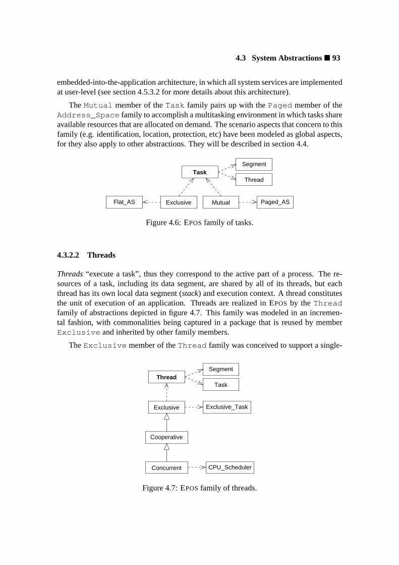
4.3 System Abstractions� 93
embedded-into-the-application architecture, in which all system services are implementedat user-level (see section 4.5.3.2 for more details about this architecture).
The Mutual member of theTask family pairs up with thePaged member of theAddress_Space family to accomplish a multitasking environment in which tasks shareavailable resources that are allocated on demand. The scenario aspects that concern to thisfamily (e.g. identification, location, protection, etc) have been modeled as global aspects,for they also apply to other abstractions. They will be described in section 4.4.
Task
Exclusive Mutual Paged_ASFlat_AS
Segment
Thread
Figure 4.6: EPOSfamily of tasks.
4.3.2.2 Threads
Threads“execute a task”, thus they correspond to the active part of a process. The re-sources of a task, including its data segment, are shared by all of its threads, but eachthread has its own local data segment (stack) and execution context. A thread constitutesthe unit of execution of an application. Threads are realized in EPOS by theThreadfamily of abstractions depicted in figure 4.7. This family was modeled in an incremen-tal fashion, with commonalities being captured in a package that is reused by memberExclusive and inherited by other family members.
TheExclusive member of theThread family was conceived to support a single-
Cooperative
Concurrent
Exclusive
Thread
Exclusive_Task
CPU_Scheduler
Segment
Task
Figure 4.7: EPOSfamily of threads.
94� Chapter 4: The EPOS System
threaded process that executes alone in the system. It depends on theExclusive mem-ber of theTask family, which ultimately shapes the single-tasking environment in whichexclusive threads perform. Though primitive4, this process model is sufficient to sup-port a reasonable number of dedicated applications, and it has expressive advantages overother models in what regards performance. Since all resources available in the systemare pre-allocated to this unique process during system initialization, and also becauseno scheduling is necessary, this process model can be achieved without any run-timeoverhead, i.e., all physical resources, including CPU time, are entirely available to theapplication process.
Support for multithreading is the subsequent increment to theThread family. It isrealized by theCooperative family member, which covers the mechanisms necessaryfor multiple threads to coexist in the system. This family member was conceived to beindependent of the task model in force, so no differentiation is made between threads thatexecute the same task and threads of single-threaded tasks. As stated before, the unit ofexecution in EPOS is the thread, not the task. TheCooperative thread abstractionaddresses the issues relative to multiple threads that share the processor in a collabora-tive way, dispensing with processor scheduling. In this scenario, a thread voluntarilyrelinquishes the processor in favor of another one; hence, one could say that cooperativethreads are self-scheduling.
The Concurrent abstraction extends theThread family so that threads are exe-cuted concurrently. This family member relies on a family of processor schedulers, eachimplementing a different scheduling policy, in order to multiplex the processor amongthreads. According to the scheduling policy in force, the scheduler can be invoked reg-ularly to proof whether the running thread still fulfills the necessary conditions to seizethe processor, otherwise preempting it in favor of another thread. Being an extension ofcooperative threads, concurrent threads also have the possibility to voluntarily relinquishthe processor, either in benefit of another thread, or causing the scheduler to be invoked.
4.3.2.3 Processor Schedulers
Processor scheduling is deployed in order to multiplex the processor for concurrent threadexecution. Therefore, EPOS only features a processor scheduler if theConcurrentmember of theThread family is in use. In this case, the scheduler is realized by theentities shown in figure 4.8. TheCPU_Scheduler abstraction realizes the mechanismsthat are necessary to suspend and resume the execution of threads (i.e. context switching),invoking Policy to select a thread to occupy the processor whenever it becomes idle.That is, EPOSdoes not actually feature a family of schedulers, but a family of schedulingpolicies that are enforced by a singleCPU_Scheduler abstraction.
The isolation of scheduling policies was achieved by modelingPolicy as a polymor-
4Only three operations are valid on objects of typeExclusive_Thread : self-referencing, statusreporting, and termination.

4.3 System Abstractions� 95
phic uniform family of abstractions. In this way,CPU_Scheduler can invokePolicywithout having to consider which policy is currently in force, and policies can be changedat run-time. In order to configure the scheduler, one or more policies are selected atgeneration-time to be deployed at run-time. Since the processor scheduler is an internalentity, invisible to applications, the selection of policies at run-time is performed throughoperations provided by theConcurrent thread abstraction.
If one of the scheduling policies selected for a given system configuration is pre-emptive, thepreemption configurable feature is enabled, causing the scheduler to beperiodically activated by theAlarm abstraction [section 4.3.5] to check for policy com-pliance. A thread that voluntarily relinquishes the processor also causes the scheduler tobe activated. If the leaving thread indicates a candidate to replace it on the processor, thatthread temporarily assumes the scheduling characteristics of the leaving one. For exam-ple, if static priority is the policy in force, then the priority of the designated thread israised to equal that of the designator until the next scheduling event. Otherwise, a threadcan relinquish the processor leaving the decision of which thread shall substitute it to thepolicy enforcer.
A third situation in which the scheduler can be activated occurs when a concurrentthread goes waiting for an event, for example I/O completion. The traditional approachof generic multitasking systems to deal with this situation is to block the waiting threadand invoke the scheduler to select another thread to occupy the processor. In this scheme,blocked threads are said to be “idle waiting”. Nevertheless, this solution is not so straight-forward for dedicated systems, which may be better served if “busy waiting” is deployed.Several high-speed peripherals, including high-speed networks, may imply in busy wait-ing cycles that are shorter than the time needed to block the running thread and reschedulethe processor. Therefore, busy and idle waiting have been modeled as configurable fea-tures that can be selected according to application needs.
preemption
idle_waiting
busy_waiting
affinity
RRFCFS Static_Priority User_Defined
Policy
CPU_Scheduler Alarm
Dynamic_Priority
Multilevel
Figure 4.8: EPOSfamily of processor scheduling policies.

96� Chapter 4: The EPOS System
TheCPU_Scheduler abstraction is also able to perform processor scheduling in aSymmetric MultiProcessor(SMP) environment [JS80, TG89]. Regardless of the numberof processors, a single queue of threads ready to execute is maintained. When a processorbecomes idle,CPU_Scheduler is invoked by that processor to select a new threadto execute. Race conditions originated from parallel invocations of the scheduler areprevented by activating one of theLocked members of theAtomic scenario aspect (seesection 4.4.6)5.
In multiprocessor environments, the configurable featureaffinity can be enabledto requestCPU_Scheduler to consider processor affinity [TTG93] while choosing athread to occupy an idle processor, so that threads that were formerly executing on thatprocessor are given preference. If the scheduler cannot find a thread under the affinitycriterion, a thread formerly executed in another processor is selected. Processor affinityis useful with short-term scheduling to promote cache locality, since a thread returning toa processor it has recently seized may still find part of its working-set of memory on thatprocessor’s cache.
TheFCFSmember of thePolicy family realizes thefirst-come-first-servedschedul-ing policy. When concurrent threads operate under this policy, they acquire several of thecharacteristics of a cooperative thread, for a thread only releases the processor on its ownfree will. Nevertheless, if the idle waiting configurable feature is enabled, a thread goinginto a waiting state releases the processor for the next coming thread, retrieving it when itreturns to the ready state. TheRRmember of thePolicy family realizes theround-robinprocessor scheduling policy. With this policy, the processor is multiplexed on time amongthreads, so that each thread is given an identical fraction of processing time (time-slice),after which it is preempted and sent to the end of the ready queue.
The Static_Priority member realizes a processor scheduling policy based onstatically assigned priorities [ZRS87]. When a thread is created, it is assigned a prioritythat is used for scheduling decisions: higher priority threads are executed first. Althoughapplications are provided with means to redefine the priority of a thread afterwards, thescheduler itself never takes this initiative. This policy influences the handling of asyn-chronous events in EPOS[section 4.3.6.3], since an event only causes the processor to bepreempted if the thread assigned to handle it has a higher priority than the one currentlybeing executed.
The Dynamic_Priority member extendsStatic_Priority and RR to ac-complish a policy that automatically adjusts the priority of threads to promote interac-tiveness. The strategy used to build this policy consists in allowing a thread to seize theprocessor for a certain time (usually greater than the time-slice defined for round-robin),after which it is preempted and its priority is recalculated. Priorities are recalculated as afunction of the processing time effectively used, so threads that voluntarily relinquish the
5The dependency ofCPU_Scheduler onAtomic is externally expressed as a composition rule [sec-tion 4.5.1.2]. It can be easily suppressed for eventual scheduling algorithms that are able to cope withnon-blocking synchronization.
4.3 System Abstractions� 97
processor before their time-slice is over have their priority increased, while those that tendto monopolize the processor have their priority decreased. This is basically the schedulingpolicy adopted in the UNIX SYSTEM V operating system [Bac87]. It promotes interac-tiveness because interaction with users is achieved via I/O operations, causing interactivethreads to release the processor prematurely and consequently raising their priority6.
In principle, a single processor scheduling policy is in force at a time. However, theMultilevel member of thePolicy family supports scheduling policies to be com-bined by gathering threads in groups and applying distinct inter- and intra-group policies.For example, threads could be gathered in three groups scheduled with static priorities(i.e. the inter-group policy). The group with the highest priority could again deploystatic priorities to support a set of real-time threads; the intermediate priority group, con-sisting of interactive threads, could deploy round-robin; and the group with the lowestpriority, comprised of batch threads, could be subject to FCFS. Although such a complexscheduling scenario is improbable for a dedicated system, some simpler combinations ofscheduling policies may be useful.
User_Defined , the last member of thePolicy family of abstractions, allowsapplications to specify their own processor scheduling policy. It is accomplished by amultilevel scheme that assigns the highest priority to an application thread that acts asthe scheduler, while all other threads are assigned the same lower (than the schedulerthread) priority. The scheduler thread implements the desired policy and relinquishes theprocessor in benefit of the selected thread.
A preemptive user-level scheduler [ABLL92] can be accomplished in a variety ofways, the simplest one implies in defining a round-robin policy for the high priority groupof threads, which comprises only the scheduler thread. This would grant that the sched-uler thread regains control over the processor on a regular basis. It can then decide toreschedule the thread that originally occupied the processor, or select another one. Nev-ertheless, theUser_Defined policy can considerably affect performance if used toperform short-term scheduling, since it doubles the scheduling overhead.
4.3.3 Process Coordination
The mechanisms available in EPOS to coordinate the parallel execution of processes arerealized by theSynchronizer andCommunicator families of abstractions shown infigure 4.9. However, theCommunicator family delivers coordination as a side-effect ofinter-process communication, and hence will be described later in section 4.3.4. Neverthe-less, it is important to observe that every time two processes exchange a (possibly empty)message, they implicitly exchange status information that can be used for coordinationpurposes. For example, when a process sends a message to another, it signalizes the re-cipient process that it is ready with the computation needed to produce that message. The
6In order to achieve this effect in EPOS, theidle_waiting configurable feature must be enabled.

98� Chapter 4: The EPOS System
set of possibilities to indirectly coordinate processes through message exchange growsconsiderably if inter-process communication implies in a rendezvous between the com-municating processes. In this case, sender and receiver are implicitly synchronized oneach message exchange.
Synchro−nizer nicator
Commu−
Coordi−nation
Figure 4.9: Families of abstractions concerning process coordination in EPOS.
4.3.3.1 Synchronizers
Synchronizersare used to avoid race conditions during the execution of parallel programs.A race condition occurs when a thread accesses a piece of data that is being modified byanother thread, obtaining an intermediate value and potentially corrupting that piece ofdata. A synchronizer prevents such race conditions by trapping sensible data in a criticalsection, which is exclusively executed by a single thread at a time. EPOS dissociatedfamily of synchronizers is depicted in figure 4.10.
TheMutex member of theSynchronizer family implements a simple mutual ex-clusion device that supplies two atomic operations:lock andunlock . Invoking lockon a mutex locks it, so subsequent invocations cause the calling threads to wait. When athread invokes the operationunlock on a mutex and there are threads waiting on it, thefirst thread put to wait is allowed to continue execution, immediately locking the mutex.If no threads are waiting, theunlock operation has no effect; it is not accumulated tomatch forthcominglock operations. The mutex mechanism is sometimes called abinary
remote
atomic
Synchronizer
SemaphoreMutex
Condition
Figure 4.10: EPOSfamily of synchronizers.

4.3 System Abstractions� 99
semaphore.
TheSemaphore member of theSynchronizer family realizes asemaphore vari-able[Dij65]. A semaphore variable is an integer variable whose value can only be manip-ulated indirectly through the atomic operationsp andv . Operationp atomically decre-ments the value of a semaphore, and operatingv atomically increments it. Invokingpon a semaphore whose value is less than or equal to zero causes the thread to wait untilthe value becomes positive again. A semaphore initialized with “1” acquires the initialsemantics of a mutex, but it can be initialized with any other value to accomplish othersynchronization semantics.
TheCondition member of theSynchronizer family realizes a system abstrac-tion inspired on thecondition variablelanguage concept [Hoa74], which allows a threadto wait for a predicate on shared data to become true.Condition protects the associ-ated shared data in a critical section using the capabilities inherited fromMutex . In orderto wait for the assertion of a predicate, a thread invokes operationwait , which implicitlyunlocks the shared data and puts the thread to wait. Several threads can be waiting on thesame condition. The assertion of a predicate can be announced in two ways: operationsignal announces it to the first waiting thread, and operationbroadcast announcesit to all waiting threads. When a thread returns from thewait operation, it implicitlyregains control over the critical section.
The global scenario aspectremote , which will be described later in section 4.4.7,provides a remote object invocation mechanism that shapes a distributed scenario forabstractions. When used in this scenario, abstractions of theSynchronizer familyaccomplish a centralized solution to coordinate processes of a parallel application. Thesolution consists in having one of the processes to create the synchronizer locally, whilethe remaining processes share it via the remote object invocation mechanism. However,this mechanism was not designed focusing distributed coordination and may cause a bot-tleneck in the parallel application7. Therefore, a specialization of theremote scenarioaspect has been considered for theSynchronizer family to optimize this scenario. Afully distributed solution, however, can only be achieved with the introduction of a newfamily member.
A negative specialization (cancellation) was specified for theatomic global scenarioaspect [section 4.4.6], since operations on synchronizers are inherently atomic.
4.3.4 Inter-Process Communication
Inter-process communication in EPOS is delegated to the families of abstractions shownin figure 4.11. Application processes communicate with each other using aCommuni-cator , which acts as an interface to a communicationChannel implemented over a
7The node in which the synchronizer resides becomes a kind of “coordinator”, with which all otherprocesses have to communicate.

100� Chapter 4: The EPOS System
Network . The messages sent through aCommunicator can be specified as sequencesof bytes of a known length, or they can be covered by anEnvelope .
Commu−nication
Commu−nicator Channel
Envelope
Network
Device
Figure 4.11: Families of abstractions concerning inter-process communication in EPOS.
4.3.4.1 Communicators
A communicatoris an end-point for a communication channel that enables applicationprocesses to exchange data with each other. Therefore, when an application selects acommunicator, it implicitly designates the kind of communication channel that will beused. Communicators, like most other system abstractions, are assigned to tasks, thusbeing shared by their threads. Communicators are realized in EPOSby theCommuni-cator family of abstractions shown in figure 4.12, which was modeled as a dissociatedfamily whose members can be simultaneously deployed.
TheLink member of theCommunicator family realizes an end-point for logicalconnections between processes that carry byte streams. ThePort andMailbox mem-bers realize end-points for a communication channel in which datagrams flow, but a portalways belongs to a single task, while mailboxes can be shared among tasks.
TheARM_Segment(Asynchronous Remote Memory Segment) member of theCom-municator family realizes an end-point for a communication mechanism that supportsasynchronous access to a memory segment in a remote node. This mechanism is asyn-
ARM_SegmentPortLink
AM_Handler
Mailbox
Communicator
Segment
DSM_Segment
Channel
remote
Figure 4.12: EPOSfamily of communicators.

4.3 System Abstractions� 101
chronous because processes manipulating anARM_Segmentare not implicitly synchro-nized and can corrupt the data in that segment. Data read from a remote segment becomeslocal and private to the reading process. If necessary, synchronization has to be achievedby other means (e.g. distributed semaphores). In order to use this communicator, a pro-cess specifies a memory segment on a remote node that has been previously exported byits owner. It can then invoke operations to read from and to write to this segment (asyn-chronous remote memory segments are not mapped into the address space of processes).
TheAM_Handler (Active Message Handler) member of theCommunicator fam-ily realizes an end-point for active messages [vECGS92]. The basic idea behind thisconcept is that a message, besides transporting data, also carries a reference to a handlerthat is invoked, in the context of the receiving process, to handle the message upon ar-rival. This kind of communication is sometimes called single-sided because the receiveoperation is not explicitly expressible. For this mechanism to work properly, means mustbe provided to the sending process so it can specify a handler that is valid in the contextof the destination process. The most typical answer to this issue is to deploy active mes-sages in an SPMD (Single Program, Multiple Data) environment, in which all processeshave an equivalent address space. However, indirection mechanisms and the exchange ofhandler references using other communication mechanisms are also possible.
Active messages have been modeled in EPOS in such a way that communication ishidden behind a remote handler invocation, with messages being indirectly exchanged asarguments to the handler. When a process instantiates anAM_Handler , it supplies areference to a handler on a remote process. Afterwards it can invoke the handler supply-ing arguments that are transparently marshaled in a message and delivered to the remotehandler.
TheDSM_Segmentmember of theCommunicator family, which would realize aDistributed Shared Memory(DSM) mechanism for EPOS, could have been modeled asan extension of theARM_Segment communicator and of a member of theSegmentfamily of memory segments. Unlike anARM_Segment, however, aDSM_Segmentwould be attached to the address space of processes, dispensing with explicit read andwrite operations. It would also implement a mechanism to grant data coherence. Thiscommunicator would enable application programmers to write parallel applications fordistributed memory machines as if they were shared memory ones.
A negative specialization (cancellation) was specified for theremote global scenarioaspect [section 4.4.7], since a process is not allowed to exchange messages using commu-nicators created by other processes on remote nodes.
4.3.4.2 Channels
A communicationchannelis the entity effectively responsible for inter-process commu-nication in EPOS. It uses network resources to build a logical communication channelthrough which messages are exchanged. A channel implements a communication protocol

102� Chapter 4: The EPOS System
ARMR ARMW
ARMC AM
Channel
Address_SpaceDSM
asynchronous
synchronous
grouping
buffering
DatagramStream
Network
Figure 4.13: EPOSfamily of communication channels.
that, according to theBasic Reference Model for Open Systems Interconnection(ISO/OSI-RM) [ISO81], would be classified at level four (transport). EPOS family of communica-tion channels is depicted in figure 4.13. It was modeled as a dissociated family, whosemembers are indirectly accessed through the corresponding members of theCommuni-cator family.
A communication channel has an implicit capacity [Sha48]. Trying to insert a mes-sage into a saturated channel causes the transmitter to wait until the channel can accom-modate the message. Likewise, the attempt the extract a message from an empty channelcauses the receiver to wait until a message is available. Whether a thread waiting on achannel performs busy or idle waiting hinges on the related configurable feature from theCPU_Scheduler family [section 4.3.2.3]. Notwithstanding this, a channel can haveits capacity extended by enabling thebuffering configurable feature. In this case,messages sent through a saturate channel are accumulated for posterior handling.
Sometimes it is desirable to fork a channel, so that a transmitted message is simul-taneously multicasted to several receivers, or broadcasted to all receivers. The collectiveoperations used in many parallel applications could be considerably optimized in this way.EPOSallows a channel to be forked when thegrouping configurable feature is enabled.In this case, special identifiers are supplied to designate a group of communicators as therecipient of a message. The effect ofbuffering andgrouping configurable featureson a channel is illustrated in figure 4.14.
Thesynchronous scenario aspect yields an execution scenario in which the opera-tions used to inject a message into a channel only conclude when the message is extractedfrom the channel at the receiver’s side. In a synchronous communication scenario, pro-cesses involved in a message exchange are said to make a “rendezvous”. Conversely, theasynchronous scenario aspect modifies these operations so they conclude as soon as
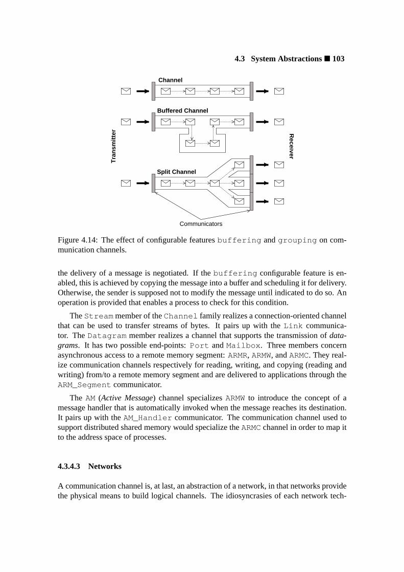
4.3 System Abstractions� 103
Tra
nsm
itte
r Receiver
Channel
Split Channel
Buffered Channel
Communicators
Figure 4.14: The effect of configurable featuresbuffering andgrouping on com-munication channels.
the delivery of a message is negotiated. If thebuffering configurable feature is en-abled, this is achieved by copying the message into a buffer and scheduling it for delivery.Otherwise, the sender is supposed not to modify the message until indicated to do so. Anoperation is provided that enables a process to check for this condition.
TheStream member of theChannel family realizes a connection-oriented channelthat can be used to transfer streams of bytes. It pairs up with theLink communica-tor. TheDatagram member realizes a channel that supports the transmission ofdata-grams. It has two possible end-points:Port andMailbox . Three members concernasynchronous access to a remote memory segment:ARMR, ARMW, andARMC. They real-ize communication channels respectively for reading, writing, and copying (reading andwriting) from/to a remote memory segment and are delivered to applications through theARM_Segmentcommunicator.
The AM(Active Message) channel specializesARMWto introduce the concept of amessage handler that is automatically invoked when the message reaches its destination.It pairs up with theAM_Handler communicator. The communication channel used tosupport distributed shared memory would specialize theARMCchannel in order to map itto the address space of processes.
4.3.4.3 Networks
A communication channel is, at last, an abstraction of a network, in that networks providethe physical means to build logical channels. The idiosyncrasies of each network tech-
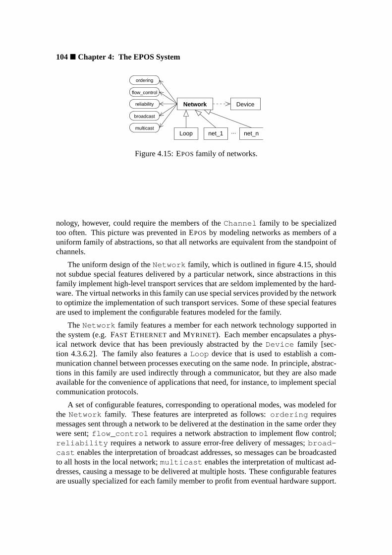
104� Chapter 4: The EPOS System
Network Device
net_nnet_1Loop ...
broadcast
ordering
flow_control
multicast
reliability
Figure 4.15: EPOSfamily of networks.
nology, however, could require the members of theChannel family to be specializedtoo often. This picture was prevented in EPOSby modeling networks as members of auniform family of abstractions, so that all networks are equivalent from the standpoint ofchannels.
The uniform design of theNetwork family, which is outlined in figure 4.15, shouldnot subdue special features delivered by a particular network, since abstractions in thisfamily implement high-level transport services that are seldom implemented by the hard-ware. The virtual networks in this family can use special services provided by the networkto optimize the implementation of such transport services. Some of these special featuresare used to implement the configurable features modeled for the family.
The Network family features a member for each network technology supported inthe system (e.g. FAST ETHERNET and MYRINET). Each member encapsulates a phys-ical network device that has been previously abstracted by theDevice family [sec-tion 4.3.6.2]. The family also features aLoop device that is used to establish a com-munication channel between processes executing on the same node. In principle, abstrac-tions in this family are used indirectly through a communicator, but they are also madeavailable for the convenience of applications that need, for instance, to implement specialcommunication protocols.
A set of configurable features, corresponding to operational modes, was modeled forthe Network family. These features are interpreted as follows:ordering requiresmessages sent through a network to be delivered at the destination in the same order theywere sent;flow_control requires a network abstraction to implement flow control;reliability requires a network to assure error-free delivery of messages;broad-cast enables the interpretation of broadcast addresses, so messages can be broadcastedto all hosts in the local network;multicast enables the interpretation of multicast ad-dresses, causing a message to be delivered at multiple hosts. These configurable featuresare usually specialized for each family member to profit from eventual hardware support.

4.3 System Abstractions� 105
Envelope
Untyped Typed
Figure 4.16: EPOSfamily of message envelopes.
4.3.4.4 Message Envelopes
The members of theCommunicator family can be used to exchange unstructured mes-sages in the form of sequences of bytes of a certain length. However, it might be adequatefor some applications to count on anenvelopeabstraction to cover a message before it issent. Such an envelope would be allocated from the operating system, loaded with one ormore messages, and then inserted into a communication channel through a communica-tor. An envelope allocated by the operating system would enable several optimizations,ranging from cache alignment to zero-copy processing. Besides, additional informationcan be put in the envelope to describe and protect messages. After all, an envelope wouldenable a comfortable syntax to express communication in object-oriented applications,for example:
Envelope envelope(recipient, length);envelope « "Hello world!";communicator « envelope ;
EPOSsupports the concept ofmessage envelopethrough theEnvelope uniform fam-ily of abstractions represented in figure 4.16. The maximum length of message that anenvelope can hold is specified when it is instantiated, while the effective length of themessage(s) it contains is dynamically determined. An envelope must be addressed beforeit is posted.
TheEnvelope family comprises two members:Untyped andTyped . The formerrealizes a simple message envelope that can be used to gather messages before send-ing, while the latter collects type information for each message inserted to enable formatconversions on heterogeneous systems. Asecure envelopewas not modeled due to thecharacteristics of a dedicated computing system, which usually do not require encryptionnor authentication of messages8.
4.3.5 Time Management
Time is managed in EPOSby theTimer family of dissociated abstractions shown in fig-ure 4.17. TheClock abstraction is responsible for keeping track of the current time. It
8A discussion about protection in dedicated systems is presented in section 4.4.4.
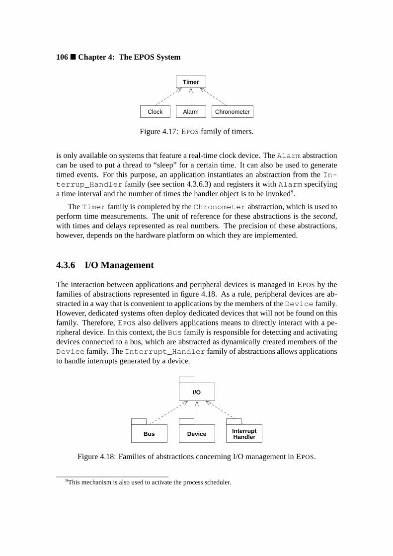
106� Chapter 4: The EPOS System
Clock Alarm
Timer
Chronometer
Figure 4.17: EPOSfamily of timers.
is only available on systems that feature a real-time clock device. TheAlarm abstractioncan be used to put a thread to “sleep” for a certain time. It can also be used to generatetimed events. For this purpose, an application instantiates an abstraction from theIn-terrup_Handler family (see section 4.3.6.3) and registers it withAlarm specifyinga time interval and the number of times the handler object is to be invoked9.
TheTimer family is completed by theChronometer abstraction, which is used toperform time measurements. The unit of reference for these abstractions is thesecond,with times and delays represented as real numbers. The precision of these abstractions,however, depends on the hardware platform on which they are implemented.
4.3.6 I/O Management
The interaction between applications and peripheral devices is managed in EPOSby thefamilies of abstractions represented in figure 4.18. As a rule, peripheral devices are ab-stracted in a way that is convenient to applications by the members of theDevice family.However, dedicated systems often deploy dedicated devices that will not be found on thisfamily. Therefore, EPOSalso delivers applications means to directly interact with a pe-ripheral device. In this context, theBus family is responsible for detecting and activatingdevices connected to a bus, which are abstracted as dynamically created members of theDevice family. TheInterrupt_Handler family of abstractions allows applicationsto handle interrupts generated by a device.
Device HandlerInterruptBus
I/O
Figure 4.18: Families of abstractions concerning I/O management in EPOS.
9This mechanism is also used to activate the process scheduler.
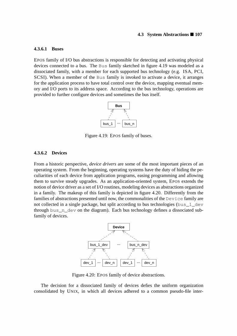
4.3 System Abstractions� 107
4.3.6.1 Buses
EPOS family of I/O bus abstractions is responsible for detecting and activating physicaldevices connected to a bus. TheBus family sketched in figure 4.19 was modeled as adissociated family, with a member for each supported bus technology (e.g. ISA, PCI,SCSI). When a member of theBus family is invoked to activate a device, it arrangesfor the application process to have total control over the device, mapping eventual mem-ory and I/O ports to its address space. According to the bus technology, operations areprovided to further configure devices and sometimes the bus itself.
Bus
bus_1 bus_n...
Figure 4.19: EPOSfamily of buses.
4.3.6.2 Devices
From a historic perspective,device driversare some of the most important pieces of anoperating system. From the beginning, operating systems have the duty of hiding the pe-culiarities of each device from application programs, easing programming and allowingthem to survive steady upgrades. As an application-oriented system, EPOS extends thenotion of device driver as a set of I/O routines, modeling devices as abstractions organizedin a family. The makeup of this family is depicted in figure 4.20. Differently from thefamilies of abstractions presented until now, the commonalities of theDevice family arenot collected in a single package, but split according to bus technologies (bus_1_devthroughbus_n_dev on the diagram). Each bus technology defines a dissociated sub-family of devices.
Device
dev_ndev_1dev_ndev_1
bus_1_dev bus_n_dev...
......
Figure 4.20: EPOSfamily of device abstractions.
The decision for a dissociated family of devices defies the uniform organizationconsolidated by UNIX , in which all devices adhered to a common pseudo-file inter-
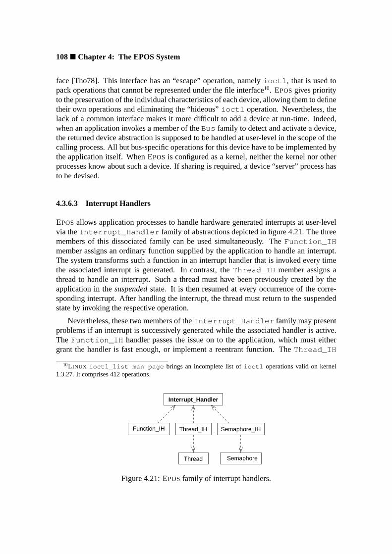
108� Chapter 4: The EPOS System
face [Tho78]. This interface has an “escape” operation, namelyioctl , that is used topack operations that cannot be represented under the file interface10. EPOSgives priorityto the preservation of the individual characteristics of each device, allowing them to definetheir own operations and eliminating the “hideous”ioctl operation. Nevertheless, thelack of a common interface makes it more difficult to add a device at run-time. Indeed,when an application invokes a member of theBus family to detect and activate a device,the returned device abstraction is supposed to be handled at user-level in the scope of thecalling process. All but bus-specific operations for this device have to be implemented bythe application itself. When EPOS is configured as a kernel, neither the kernel nor otherprocesses know about such a device. If sharing is required, a device “server” process hasto be devised.
4.3.6.3 Interrupt Handlers
EPOSallows application processes to handle hardware generated interrupts at user-levelvia theInterrupt_Handler family of abstractions depicted in figure 4.21. The threemembers of this dissociated family can be used simultaneously. TheFunction_IHmember assigns an ordinary function supplied by the application to handle an interrupt.The system transforms such a function in an interrupt handler that is invoked every timethe associated interrupt is generated. In contrast, theThread_IH member assigns athread to handle an interrupt. Such a thread must have been previously created by theapplication in thesuspendedstate. It is then resumed at every occurrence of the corre-sponding interrupt. After handling the interrupt, the thread must return to the suspendedstate by invoking the respective operation.
Nevertheless, these two members of theInterrupt_Handler family may presentproblems if an interrupt is successively generated while the associated handler is active.The Function_IH handler passes the issue on to the application, which must eithergrant the handler is fast enough, or implement a reentrant function. TheThread_IH
10L INUX ioctl_list man page brings an incomplete list ofioctl operations valid on kernel1.3.27. It comprises 412 operations.
Semaphore_IHThread_IHFunction_IH
Interrupt_Handler
Thread Semaphore
Figure 4.21: EPOSfamily of interrupt handlers.

4.3 System Abstractions� 109
handler is even more restrict in this regard, since resuming an already active thread hasno effect.
The issue of interrupt loss is addressed by theSemaphore_IH , which assigns asemaphore, previously created by the application and initialized with zero, to an interrupt.The operating system invokes operationv on this semaphore at every interrupt, while thehandling thread invokes operationp to wait for an interrupt. The strategy gives interrupthandling a producer/consumer flavor and prevents interrupts from being lost.
Nevertheless, preventing interrupts from being lost may not be enough to grant thatI/O data will not be lost. A device that generates a subsequent interrupt while a formeris still being handled must have memory to accumulate eventual data. If this is not thecase, a handler must be conceived that is able to match up the device’s operational speed.Moreover, depending on the scheduling policy in force, interrupts may not be handledimmediately. For example, if the thread responsible for handling an interrupt has a lowerpriority than the thread currently being executed, the handler will be enqueued for laterexecution.
4.3.7 External Abstractions
Some of the system services offered by EPOSare not implemented on the dedicated com-puting system itself, but on an external server. For example, file services and graphicoutput. In order to enable these services to be remotely accessed, EPOScommunicationsystem is emulated over an ordinary operating system. A computer running this emulatorbecomes a gateway to an EPOS-based environment that allows external abstraction to beaccessed via remote object invocation (see section 4.4.7). This scheme is illustrated infigure 4.22 (EPOS is represented in the figure on its most typical architecture, i.e. fullyembedded in the application).
The set of “stub” functions used to perform remote invocation can also be used to giveexternal services an EPOS-flavor. For instance, POSIX file operations can be deliveredthrough a file abstraction.
EPOS
application
EPOS Node
server
EPOSGenericOS
Server
network
Figure 4.22: Access to external abstractions in EPOS.

110� Chapter 4: The EPOS System
4.3.8 Summary of EPOS Abstractions
A summary of EPOSabstractions is presented in tables 4.1 and 4.2. Families of abstrac-tions are grouped by category. A brief description of responsibilities, type, and dependen-cies are given for each family and for each member of a family.
Family Responsibilities Type Dependencies
Memory Management
Segment logical memory segments ⊕ Address_SpaceStatic not resizable, flags not changeable ♦? -Dynamic resizable, remappable ♦? Paged
Address_Space logical address space of a process -Flat single, contiguously mapped address space �? -Paged multiple, paged address spaces �? -
Process Management
Task code, data, and resources of a process SegmentExclusive single-tasking ♦? FlatMutual multitasking ♦? Paged
Thread stack and context of a process ⊕ SegmentExclusive single-threading ♦? Exclusive_TaskCooperative cooperative multithreading (no scheduler) ♦? -Concurrent concurrent, scheduled multithreading ♦? CPU_Scheduler
CPU_Scheduler processor scheduling policies � AlarmFCFS first-come-first-served �? -RR round-robin �? -Static_Prio static priorities �? -Dynamic_Prio dynamic priorities �? RR,Static_PrioMultiLevel multiple policies � -UserDef user defined policy ♦ -
Process Coordination
Synchronizer process coordination -Mutex mutual exclusion device ♦ -Semaphore semaphore variable ♦ -Condition condition variable ♦ -
Family types: ⊕ incremental, dissociated, � uniform.Member types: ♦ visible to applications, � invisible, ? mutually exclusive.
Table 4.1: EPOSabstractions (part I).

4.3 System Abstractions� 111
Family Responsibilities Type Dependencies
Inter-Process Communication
Communicator communication end-points ChannelLink connection for streams ♦ StreamPort non-sharable mailbox for datagrams ♦ DatagramMailbox sharable mailbox for datagrams ♦ DatagramARM_Segment asynchronous remote memory segment ♦ ARMxAM_Handler active message handler ♦ AM
Channel communication channels NetworkStream streams � -Datagram datagrams � -ARMR asynchronous remote memory read � -ARMW asynchronous remote memory write � -ARMC asynchronous remote memory copy � -AM active messages � -
Network logical networks (OSI level 4) � DeviceSeveral not covered in this table ♦
Envelope message envelopes � -Untyped envelope for untyped messages ♦ -Typed envelope for typed messages (heterogeneity) ♦ -
Time Management
Timer time keeping -Clock current time keeping ♦ -Alarm timed event generation ♦ -Chronometer time measurement ♦ -
I/O Management
Bus device detection and activation -Several not covered in this table ♦
Device physical device abstraction -Several not covered in this table ♦
Interrupt_Handler interrupt handling -FunctionIH calls a handling function ♦ -ThreadIH resumes a handling thread ♦ ThreadSemaphoreIH invokes v on a handling semaphore ♦ Semaphore
Family types: ⊕ incremental, dissociated, � uniform.Member types: ♦ visible to applications, � invisible, ? mutually exclusive.
Table 4.2: EPOSabstractions (part II).

112� Chapter 4: The EPOS System
4.4 Scenario Aspects
Application-oriented system design is particularly concerned with scenario independence.When a domain entity is identified, considerations about its origin are made in order todecide whether it will shape an abstraction or a scenario aspect. EPOSscenario aspectswere modeled in accordance with this principle, yielding reusable pieces of software thatcan be controllably applied to the system abstractions described in the previous section.
Likewise system abstractions, EPOSscenario aspects were organized in families ac-cording to what they have in common. The commonalities of each family are capturedin a common packagethat is reused by member aspects. Accordingly, families of aspectswere classified asuniform, incremental, dissociated, or combined.
In order to build a scenario for an application, selected scenario aspects are merged ina scenarioconstruct and applied to abstractions by means of ascenario adapter. Thesetwo constructs, however, will be described in the scope of EPOScomponent frameworklater in section 4.5.1.
4.4.1 Identification
“An object has state, behavior, and identity.”
(Grady Booch [Boo94])
This axiom of object-orientation, which evidently also applies to the instances of sys-tem abstractions11, impart that an object has an identity that distinguishes it from all theothers. At programming language level, this identity is usually represented by the object’saddress in memory (pointer). This form of identity is rather adequate if objects are onlymanipulated in the scope of the process that created them, but it is inadequate to identifyobjects that are shared by multiple processes. In this case, the operating system has theduty of generating identifiers for system objects that are able to distinguish them acrossall processes. If objects can be shared in a distributed environment, identifiers must beextended to accomplish unique identification across all nodes in the platform. This vari-ability concerning the identity property is typical of scenario aspects, for it affects themanifestation of an abstraction in a scenario, but not its internal structure.
Therefore, the identity of system objects was modeled in EPOSas an incremental fam-ily of scenario aspects. This family is represented in figure 4.23. MemberPointer , thefamily’s basic aspect, simply reuses the fundamental identity of objects, i.e. their addressin memory. Since this form of identifier is always relative to the address space of the pro-cess that created the object, it cannot be used for inter-process interactions on objects. TheLocal member extends theId family with an identifier that consists of a pair(type,
11Instances of system abstractions will be designated “system objects” hereafter, or simply “objects”when no confusion can arise. In this sense, an abstraction corresponds to a “class of system objects”.

4.4 Scenario Aspects� 113
randrand len. Capability
Local
Global
Id
Pointer
type unit host
type unit
type hostunit
Figure 4.23: EPOSfamily of identification aspects.
unit) and uniquely identifies a system object in a stand-alone system configuration. Thetype field is obtained from thetraits of an abstraction [section 4.5.1], whileunit repre-sents the rank of an object in the allocation table of its class. Hence, the first instance of aMyrinet network abstraction would be identified as(Traits<Myrinet>::type,0) .
MemberGlobal extends theId family so that a network-wide identifier is assignedto system objects, allowing them to be remotely accessed. The structural extension suc-ceeded by this member consists of adding a logical host number to identifiers, yieldingthe tuple(host, type, unit) . Although embedding location in identifiers compli-cates the migration of objects in a distributed environment, EPOSopted for this solutionbecause it is efficient and fulfills the demands of most parallel systems. Differently fromdistributed systems, dedicated parallel systems seldom deploy object migration due tothe high overhead associated. Other load balancing techniques that do not conflict withtheGlobal identifier, such as data set partitioning and global scheduling, are often pre-ferred [SP94b]. Nevertheless, the logical ids realized by this family could be locallyremapped to reflect the location of migrated objects.
Local andGlobal identifiers have a lifetime that corresponds to the lifetime of thesystem. That is, if a process creates a system object and later deletes it, a newly createdobject may be assigned the same identifier formerly assigned to that object. This, how-ever, should not disturb applications, since EPOSkeeps a reference counter that preventsobjects in a shared scenario (i.e. a scenario for which theShared aspect [section 4.4.2]has been enabled) from being deleted while there are still processes using it. Nonetheless,flawed programming may cause a process to keep on using an identifier after the respec-tive system object has been destroyed, inadvertently accessing another object. If these

114� Chapter 4: The EPOS System
incidents are to be handled by the operating system, theCapability identifier must beused, since its lifetime is restricted to the lifetime of the object it identifies.
TheCapability identifier extends theId family by adding a randomly generatednumber to theGlobal identifier. System objects are thus identified by the tuple(host,type, unit, rand) . Therand field makes identifiers sparse, reducing the proba-bility of an identifier being reused to a negligible level [MT86]. The exact length of thisfield, however, depends on the quality of the random number generator used and on thedynamics and lifetime of applications. Hence, it was modeled as a configurable feature.
4.4.2 Sharing
There are many reasons that lead processes to share resources. Synchronizers are sharedto accomplish coordination, memory segments are shared as an intra-node communica-tion mechanism, mailboxes are shared to support sever replication, and so forth. Whensystem resources are shared, the operating system has to provide means to preserve theirintegrity. For example, if a shared resource has its state modified by one of the shar-ing processes, the remaining must be assured a coherent view of it. In particular, whena shared resource is destroyed by one of the sharing processes, subsequent operationsinvoked by the remaining processes have to be handled accordingly.
EPOSsupports abstractions to be shared through theShared incremental family ofscenario aspects depicted in figure 4.24. When this aspect is enabled, abstractions aretagged with a reference counter by theReferenced family member, so that a sharedabstraction is actually only destroyed when the last sharing process releases it. This sce-nario aspect is specialized for the family of memory segments [section 4.3.1.1] to provideadequate support for memory sharing.
TheEnrolled member of theShared family of aspects extendsReferenced tosustain multitasking configurations of EPOS in which resources need to be reclaimed. Inthis scenario, EPOStakes note of which tasks are sharing each resource, so that resourcesnot returned by an exiting process can be reclaimed.
When theShared aspect is enabled, system abstractions gain two extra construc-
Referenced
Shared
Enrolled
Referenced<Segment>
Figure 4.24: EPOSfamily of sharing aspects.
4.4 Scenario Aspects� 115
tors12 that are used to designate sharing. The first is the ordinary copy constructor, whichtakes a reference to an existing system object as argument and returns a share to that ob-ject. This constructor is restricted to share abstractions inside the same address space.The second constructor takes an identifier as argument and therefore can be used inde-pendently of locality, inclusive to share remote objects. A C++ program could deploythese constructors as follows:
Abstraction instance;Abstraction share1(instance);Abstraction share2(share1.id ());
4.4.3 Allocation
In all-purpose operating systems, the memory internally used to store the state of system-level abstractions is expected to be dynamically allocated, since it is impossible to predictwhich abstractions and how many instances of each abstraction will be effectively re-quired by forthcoming applications. Some dedicated computing systems, however, havea predictable demand for resources. In these cases, pre-allocating resources may signif-icantly enhance performance. For example, if a process is known to spawnn threads,pre-allocating these threads—partially initializing the associated control structures andallocating the corresponding stacks—may eliminate a considerable fraction of the threadcreation overhead.
A more imperative reason to avoid dynamic memory allocation can be observed forabstractions that have (part of) their state stored outside main memory. Several abstrac-tions of physical devices fall in this category. If the device includes memory that is sharedwith the main processor, or if it memory-maps control registers, then the correspondingsystem abstraction will have part of its state mapped over the I/O bus. A dynamic mem-ory allocator unaware of such particularities would allocate incoherent instances of theabstraction; making the memory allocator aware of them would compromise portability,for device mapping is an operation that depends on the I/O bus. Situations like this couldbe handled by an utility that would execute previously to the operating system to pre-allocate indicated abstractions, delivering them later to the operating system. One such asetup utility was designed for EPOSand will be described later in section 4.5.2.1.
EPOSsupports two allocation scenarios for abstractions:Late andAhead . Both aremodeled as members of theAllocated dissociated family of scenario aspects presentedin figure 4.25. The former member defines a scenario in which the memory needed to holdthe state of system abstractions is dynamically allocated as the abstraction is instantiated,while the latter assumes it has been previously allocated. TheAhead aspect relegates
12The termconstructoris being used here independently from the C++ programming language to des-ignate a function used to instantiate an object. Applications written in programming languages that do notexplicitly support the concept would be supplied operations with equivalent semantics.

116� Chapter 4: The EPOS System
Allocated
nAheadLate Abstraction
Figure 4.25: EPOSfamily of allocation aspects.
Protected
Checked
Enrolled
Capability
Permitted<Segment>Permitted
Figure 4.26: EPOSfamily of protection aspects.
the allocation of many abstractions to marking instances “busy”. EPOSknows how manyinstances of an abstraction have been pre-allocated consulting itstraits.
A scenario in which theLate_Allocated aspect is used with exclusivity is notprobable, since some abstractions (e.g. devices) will always be allocated in advance.Therefore, the application of this scenario aspect must be evaluated individually for eachabstraction (consulting itstraits).
4.4.4 Protection
In multitasking environments, various processes compete for memory, processor, net-work, and other system resources. In such environments, aprotectionmechanism toensure thatprocessesdo not inappropriately interfere with one another’s activities is de-sirable. In order to gain access to resources, processes would thus have to obtain explicitauthorization from the operating system.
Protection in generic systems tends to extend towardssecurity, which concerns pre-venting unauthorizedusersfrom interfering with ongoing computations. However, themechanisms of authentication and encryption used in the scope of distributed and web-based computing to attain security are rarely required for dedicated computing, because,as a matter of fact, dedicated systems are (temporary) single-user systems. Therefore,EPOSprotection mechanisms are restricted to control access to resources. These mecha-nisms are modeled by theProtected incremental family of scenario aspects depictedin figure 4.26.
The Checked aspect of theProtected family profits from theCapability

4.4 Scenario Aspects� 117
identifier described in section 4.4.1 as a protection mechanism. That identifier uses asparse random number to achieve identification uniqueness, which can also serve protec-tion purposes: in order to access a system object, a process has to know its capability. Theprobability of gaining access to an object by betting can be made insignificant if capabil-ities are sufficiently sparse, what is controlled by therandom_length configurablefeature of theCapability aspect. Lengths ranging from 32 to 64 bits shall be in orderfor most systems.
ThePermitted protection aspect extendsChecked to build a protection scenarioin which operations on abstractions are individually authorized or denied for each pro-cess [MT86]. In order to achieve this scenario,Permitted wraps the random num-ber generator used by theCapability , adding permission flags to therand field (therand_length configurable feature is adjusted to accommodate these extra bits). A newoperation on objects of typeCapability is supplied that produces restricted versionsof a capability as a non-reversible function of the unrestricted version (theownercapabil-ity). A list with owner capabilities corresponding to the objects created by each processis maintained by theEnrolled sharing aspect. Access control is thus enforced by thescenario adapter, which checks for permission before allowing an operation to proceed.
This family of scenario aspects is specialized for theSegment abstraction [sec-tion 4.3.1.2] to accomplish memory protection if the hardware so allows. In this way,segments are attached to the address space of a process respecting the permissions in thesupplied capability. Memory protection is also useful in single-tasking environments: byproperly protecting segments, programming mistakes such as “lost pointers” can be de-tected, thus helping to debug applications. When protection is violated, EPOSproducesa useful report of the circumstances. Besides, EPOS always protects its own memorysegments when theProtected scenario is enabled.
4.4.5 Timing
A thread often goes waiting for events such as I/O completion, thread termination, andmessage arrival. Some of these events, however, may suffer delays beyond acceptablelimits; some may not occur at all. In some cases, it may be more adequate for an applica-tion to lose a message sent over a jammed network than delaying a computation to waitfor it. Similarly, it may be better for a control application to succeed a predefined actionthan missing a deadline waiting for user intervention. Such situations can be managed byassigning a time limit to operations that may cause a thread to wait. If the operation doesnot conclude within the specified interval, it is terminated by the operating system with afailure status.
A mechanism to specify time-outs for operations was modeled in EPOS as a globalscenario aspect. However, associating time-outs to operations that are not eligible tosuffer delays would add unnecessary overhead to the system. Therefore, theLimitedscenario aspect responsible for time-outs is only applied to abstractions after consulting

118� Chapter 4: The EPOS System
Timed
Limited DelayedAlarm
Figure 4.27: EPOSfamily of timing aspects.
their traits [section 4.5.1]. This scenario aspect belongs to theTimed dissociated familyrepresented in figure 4.27.Limited relies on theAlarm timer to implement time-outs.
A timing aspect that is less often deployed is realized by theDelayed member ofthe Timed family. It supports operations on system abstractions to be delayed by acertain time. It is useful, for instance, to migrate embedded applications with strict timingdependencies to a faster hardware platform, or to achieve a homogeneous execution timefor processes of a parallel application running on heterogeneous speed nodes.
4.4.6 Atomicity
Events in a parallel program are no longer strictly ordered as in sequential programs, theycan occur simultaneously. When multiple threads are allowed to execute in parallel, itits possible that they simultaneously “enter” the operating system, i.e. pass to executeoperating system code to accomplish a system service. An operating system that allowsfor this scenario is said to be reentrant and is itself subject to race conditions. Reentranceis often approached in monolithic systems by properly coordinating the execution of crit-ical sections identified in the course of system development. The dynamic architecture ofan application-oriented operating system, however, makes this solution impractical. Thecombination of abstraction, aspects, and configurable features may have profound conse-quences on system architecture, invalidating some of the hand-made critical sections.
Therefore, EPOShandles the synchronization pitfalls brought about by reentrance en-suring that system operations areatomic. In this way, transformations of the state ofsystem objects either occur completely or do not occur at all. The atomicity property wasmodeled to be orthogonal to abstractions, yielding the uniform family of scenario aspectsdepicted in figure 4.28.
TheUninterrupted aspect achieves atomicity by disabling the generation of hard-ware interrupts that could cause the processor to be preempted from a thread in the middleof a system operation. This family member has a low overhead, but it may also have un-desirable side-effects on applications. Disabling interrupts may spoil I/O subsystems dueto delays in interrupt handling and cause “scheduling skew”. Furthermore, theUnin-terrupted scenario aspect is not suitable to be used in multiprocessor environments,since threads executing in parallel can simultaneously invoke system abstractions inde-pendently of interrupts.
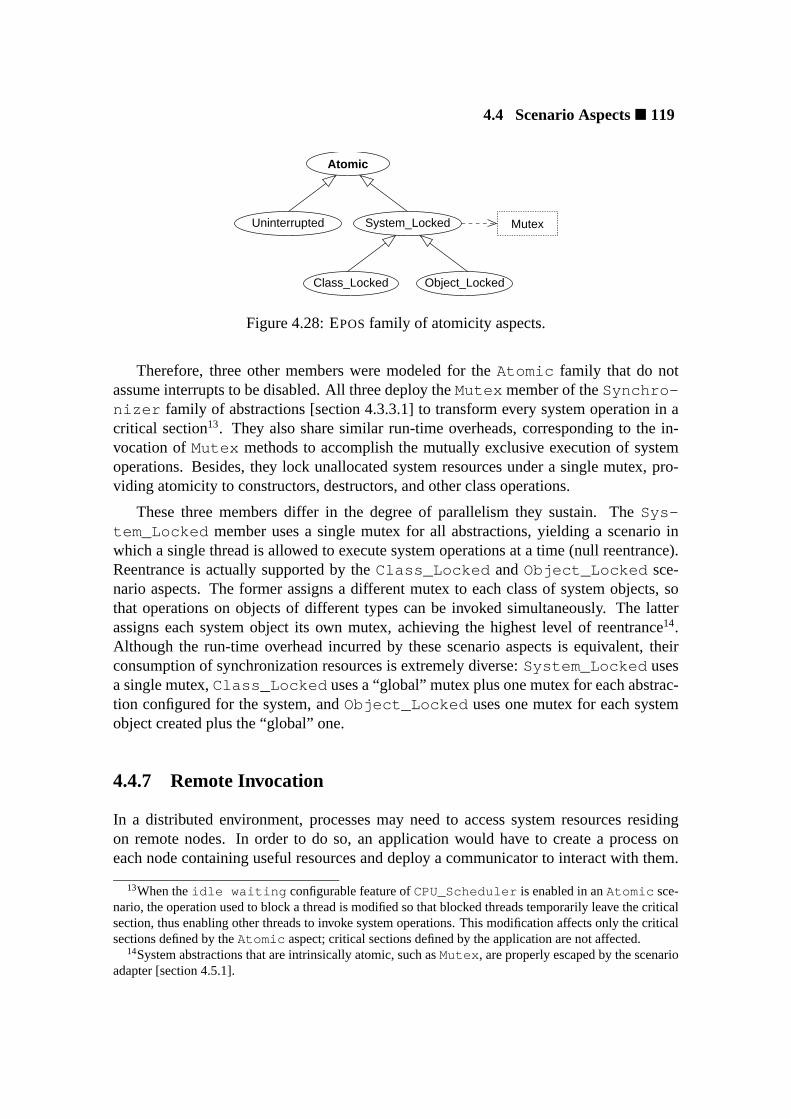
4.4 Scenario Aspects� 119
System_LockedUninterrupted
Atomic
Object_LockedClass_Locked
Mutex
Figure 4.28: EPOSfamily of atomicity aspects.
Therefore, three other members were modeled for theAtomic family that do notassume interrupts to be disabled. All three deploy theMutex member of theSynchro-nizer family of abstractions [section 4.3.3.1] to transform every system operation in acritical section13. They also share similar run-time overheads, corresponding to the in-vocation ofMutex methods to accomplish the mutually exclusive execution of systemoperations. Besides, they lock unallocated system resources under a single mutex, pro-viding atomicity to constructors, destructors, and other class operations.
These three members differ in the degree of parallelism they sustain. TheSys-tem_Locked member uses a single mutex for all abstractions, yielding a scenario inwhich a single thread is allowed to execute system operations at a time (null reentrance).Reentrance is actually supported by theClass_Locked andObject_Locked sce-nario aspects. The former assigns a different mutex to each class of system objects, sothat operations on objects of different types can be invoked simultaneously. The latterassigns each system object its own mutex, achieving the highest level of reentrance14.Although the run-time overhead incurred by these scenario aspects is equivalent, theirconsumption of synchronization resources is extremely diverse:System_Locked usesa single mutex,Class_Locked uses a “global” mutex plus one mutex for each abstrac-tion configured for the system, andObject_Locked uses one mutex for each systemobject created plus the “global” one.
4.4.7 Remote Invocation
In a distributed environment, processes may need to access system resources residingon remote nodes. In order to do so, an application would have to create a process oneach node containing useful resources and deploy a communicator to interact with them.
13When theidle waiting configurable feature ofCPU_Scheduler is enabled in anAtomic sce-nario, the operation used to block a thread is modified so that blocked threads temporarily leave the criticalsection, thus enabling other threads to invoke system operations. This modification affects only the criticalsections defined by theAtomic aspect; critical sections defined by the application are not affected.
14System abstractions that are intrinsically atomic, such asMutex , are properly escaped by the scenarioadapter [section 4.5.1].
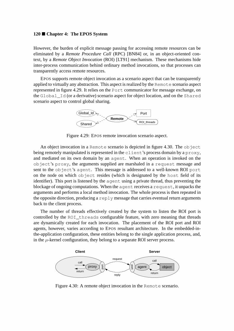
120� Chapter 4: The EPOS System
However, the burden of explicit message passing for accessing remote resources can beeliminated by aRemote Procedure Call(RPC) [BN84] or, in an object-oriented con-text, by aRemote Object Invocation(ROI) [LT91] mechanism. These mechanisms hideinter-process communication behind ordinary method invocations, so that processes cantransparently access remote resources.
EPOSsupports remote object invocation as a scenario aspect that can be transparentlyapplied to virtually any abstraction. This aspect is realized by theRemote scenario aspectrepresented in figure 4.29. It relies on thePort communicator for message exchange, ontheGlobal_Id (or a derivative) scenario aspect for object location, and on theSharedscenario aspect to control global sharing.
Global_Id
Shared
Remote
Port
ROI_threads
Figure 4.29: EPOSremote invocation scenario aspect.
An object invocation in aRemote scenario is depicted in figure 4.30. Theobjectbeing remotely manipulated is represented in theclient ’s process domain by aproxy ,and mediated on its own domain by anagent . When an operation is invoked on theobject ’s proxy , the arguments supplied are marshaled in arequest message andsent to theobject ’s agent . This message is addressed to a well-known ROIporton the node on whichobject resides (which is designated by thehost field of itsidentifier). This port is listened by theagent using a private thread, thus preventing theblockage of ongoing computations. When theagent receives arequest , it unpacks thearguments and performs a local method invocation. The whole process is then repeated inthe opposite direction, producing areply message that carries eventual return argumentsback to the client process.
The number of threads effectively created by the system to listen the ROI port iscontrolled by theROI_threads configurable feature, with zero meaning that threadsare dynamically created for each invocation. The placement of the ROI port and ROIagents, however, varies according to EPOS resultant architecture. In the embedded-in-the-application configuration, these entities belong to the single application process, and,in theµ-kernel configuration, they belong to a separate ROI server process.
proxy
port objectagent
port
request
reply
Client
return
call
Server
return
call
Figure 4.30: A remote object invocation in theRemote scenario.

4.4 Scenario Aspects� 121
Applying theRemote scenario aspect to abstractions would require a special sce-nario adapter, able to cope with proxies and agents. This could be a problem for ordinaryscenario adapters that are hand-written, since a new adapter would have to be definedfor every abstraction. This problem was eliminated by inserting placeholders in EPOS
component framework to install ROI proxies and agents (figure 4.31), which can be au-tomatically generated from the interface of abstractions by a tool (see section 4.6 for adescription of how EPOS syntactical analyzer can be used to obtain the operation sig-natures of all abstractions). These proxies and agents would be arranged in the properplaces whenRemote is enabled, being replaced by metaprogrammed dummies, whichare completely eliminated during compilation, otherwise.
A remote object invocation is firstly expressed in a program using the extra constructordefined by theShared aspect for all system abstractions. A process knowing the idof a remote object can use such a constructor to obtain a remote share of the object.Subsequently, that process can invoke operations on the object disregarding locality. Forexample, a remote thread could be suspended as follows:
Thread thread(remote_thread_id);thread.suspend ();
and a thread could be created on a remote node in this way:
Thread remote_thread(remote_task_id, entry_point, arguments ...);
The actual owner of this thread would be the ROI agent on the node where it was created.
4.4.8 Debugging and Profiling
Being able to trace the invocation of system operations, or to watch the state of sys-tem abstractions, can be useful to debug application programs. Likewise, being able tosummarize how much time an application spends with each system abstraction may be asource of optimization.
EPOSsupports these features through theDebugged family of dissociated scenarioaspects depicted in figure 4.32. The device used to report debugging and profiling infor-mation is selected through theoutupt_dev configurable feature. The scenario aspects
AgentProxy Abstraction
Scenario Adapter
Client
Figure 4.31: TheRemote scenario aspect adapter.

122� Chapter 4: The EPOS System
in this family are interpreted as follows:Watched causes the state of a system object tobe dumped every time it is modified;Traced causes every system invocation to be sig-nalized; andProfiled audits the time spent by a process with each system operation,producing a report when the process terminates. The amount of information produced foreach abstraction is controlled by itstraits.
Debuggedoutput_dev Device
TracedWatched Profiled Chronometer
Figure 4.32: EPOSfamily of debugging and profiling aspects.

4.4 Scenario Aspects� 123
4.4.9 Summary of EPOS Scenario Aspects
A summary of EPOS scenario aspects is presented in table 4.3. A brief description ofresponsibilities and dependencies are given for each family of scenario aspects and foreach member of a family.
Scenario Aspect Responsibilities DependenciesIdentification ?⊕ system object identification -
Pointer intra-process id -Local local node id -Global SAN-wide id -Capability sparse SAN-wide id -
Sharing ?⊕ sharing of system objects among processes -Referenced reference counter -Enrolled clients list -
Allocation memory allocation for system objects -Late dynamic allocation -Ahead pre-allocation Setup
Protection ?⊕ system object access control -Checked id knowledge CapabilityPermitted permitted operations Enrolled
Timing system operations timing AlarmLimited time-out -Delayed delay -
Atomicity ?� system operations reentrance -Uninterrupted interrupt disabling -System_Locked global monitor MutexClass_Locked abstraction monitor MutexObject_Locked system object monitor Mutex
Remote remote object invocation Port,Global_Id,Shared
Debugging system debugging and profiling DeviceWatched system object watching -Traced system operation tracing -Profiled system operation profiling -
Aspect types: ⊕ incremental, dissociated, � uniform. ? mutually exclusive.
Table 4.3: EPOSscenario aspects.

124� Chapter 4: The EPOS System
4.5 System Architectures
As an application-oriented operating system, EPOShas a highly scalable architecture thatis modeled to accomplish the needs of applications it supports. Ultimately, EPOS ar-chitecture results from the organization of the components selected for a given systemconfiguration. Distinct combinations of system abstractions and scenario aspects lead todifferent software architectures, some of which are delivered as a kernel, others are com-pletely embedded in the application. Therefore, the component framework representsthe core of EPOSsoftware architecture, for it dictates how abstractions can be combinedconsidering the peculiarities of the target execution scenario.
Notwithstanding the significance of a component framework to an application-oriented system design, a thorough handling of portability and initialization issues isfundamental to accomplish a scalable system architecture. If hardware architectural as-pects are absorbed by the operating system’s software architecture, porting it to anotherplatform could obliterate much of the flexibility offered by the component framework.Besides, the bare hardware on which an operating system performs is seldom prepared todeal with the high-level language constructs of a component framework. The hardwareplatform has to be appropriately initialized to house a composite of application-orientedsystem abstractions.
4.5.1 Component Framework
An application-oriented component framework captures elements of reusable system ar-chitectures while defining how abstractions can be arranged together in a functioningsystem. In this context, EPOS component framework was modeled as a collection ofinterrelated scenario adapters that build a “socket board” for system abstractions and sce-nario aspects. These are “plugged” to the framework via inflated interface binding.
EPOS component framework is realized by astatic metaprogramand a set ofcom-position rules. The metaprogram is responsible for adapting system abstractions to theselected execution scenario and arranging them together during the compilation of anapplication-oriented version of EPOS. Rules coordinate the operation of the metapro-gram, specifying constraints and dependencies for the composition of system abstractions.Composition rules are not encoded in the metaprogram, but specified externally. They areinterpreted by composition tools in order to adjust the parameters of the metaprogram.
The separation of composition rules from the framework metaprogram allows a singleframework to yield a variety of software architectures. Indeed, one could say that EPOS
has many frameworks, each corresponding to the execution of the metaprogram with adifferent set of arguments. Moreover, the use of static metaprogramming to composesystem abstractions does not incur in run-time overhead, thus yielding composites whoseperformance is directly derived from their parts.

4.5 System Architectures� 125
4.5.1.1 Framework Metaprogram
EPOScomponent framework metaprogramis executed in the course of a system instancecompilation, adapting selected abstractions to coexist with each other and with applica-tions in the designated execution scenario. During this process, scenario-independentabstractions have their original properties preserved, so that internal compositions canbe carried out before scenario adaptation. This is accomplished having the frameworkmetaprogram to import scenario-independent abstractions in one namespace and exportthe corresponding scenario-adapted versions in another.
For example, the cascaded aggregation ofCommunicator , Channel , andNet-work [section 4.3.4] takes place at the scenario-independent level. The resultant com-posite is later adapted to the selected scenario as a whole. Similarly, theAtomic sce-nario aspect instantiates a scenario-independentMutex [section 4.4.6], i.e. without theadaptations performed by the framework metaprogram, which might have transformed it,for instance, in a remotely accessible, shared, and protected abstraction to match up thescenario required by the application.
Figure 4.33 shows a top-view diagram of the component framework static metapro-gram. Each of the elements represented in the figure will be subsequently described. Aclass diagram representing theHandle framework element is depicted in figure 4.34.Like most other elements, parameterized classHandle takes a system abstraction (classof system objects) as parameter. When instantiated, it acts as a “handle” for the suppliedabstraction, realizing its interface in order that invocations of its methods are forwardedto Stub . Hence, system objects are manipulated by applications via their “handles”.
Handle provides additional operations to check if a system object was successfullycreated15 and to obtain its id. Besides, when theShared scenario aspect [section 4.4.2]
15The use of C++ exceptions as a mechanism to signalize system object creation failure was avoided
Handle Stub
Interface
Client
<<msg>>
0..1
Id Aspect
Adapter
Proxy
Agent
ScenarioAbstraction
Figure 4.33: A top-view of EPOScomponent framework metaprogram.

126� Chapter 4: The EPOS System
return stub−>operation(args);
...
...+remote
Handle
+Handle(...)+Handle(Id)+Handle(Handle)+valid() : Boolean+id() : Id+operation(parms) : result
Client
+operation(parms) : result
Abs
Stub<Abs, Traits<Abs>::remote>
AbsTraits
Abs
Figure 4.34: EPOSframework: theHandle element.
StubStub
AbsProxy
Abs, trueAbs, remote
AbsAdapter
Figure 4.35: EPOSframework: theStub element.
is enabled,Handle provides the extra constructors used to designate sharing in thatscenario. The aggregation relationship betweenHandle andStub enables the systemto enforce allocation via a system allocator (instead of a programming language one), thusallowing for theAllocated scenario aspect16.
TheStub framework element is depicted in figure 4.35. This parameterized class isresponsible for bridgingHandle either with the abstraction’s scenario adapter or with itsproxy. It declares two formal parameters: an abstraction and a boolean flag that designateswhether the abstraction is local or remote to the address space of the calling process.By default,Stub inherits the abstraction’s scenario adapter, but it has a specialization,namelyStub<Abs, true> , that inherits the abstraction’s proxy. Therefore, makingTraits<Abstraction>::remote = false causesHandle to take the scenarioadapter as theStub , while making ittrue causesHandle to take the proxy.
because it would make difficult the integration of EPOS with applications written in other programminglanguages.
16The allocator used with each abstraction is selected byAdapter after consultingTraits<Abs>::allocated .
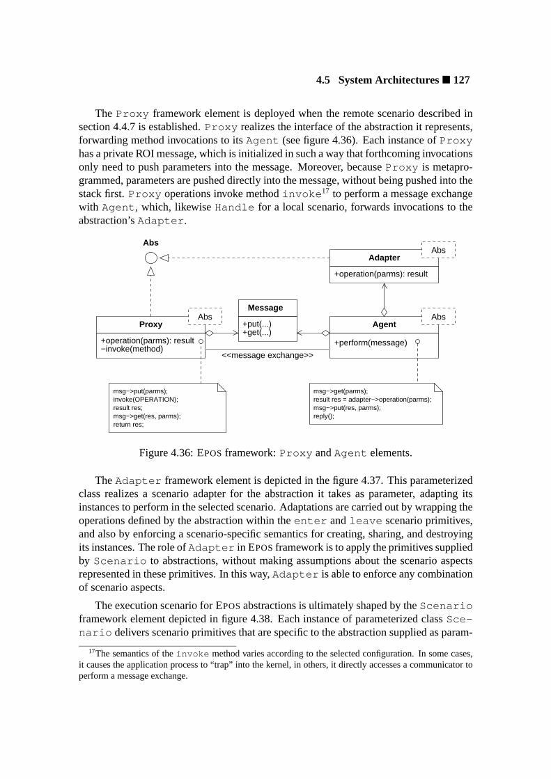
4.5 System Architectures� 127
The Proxy framework element is deployed when the remote scenario described insection 4.4.7 is established.Proxy realizes the interface of the abstraction it represents,forwarding method invocations to itsAgent (see figure 4.36). Each instance ofProxyhas a private ROI message, which is initialized in such a way that forthcoming invocationsonly need to push parameters into the message. Moreover, becauseProxy is metapro-grammed, parameters are pushed directly into the message, without being pushed into thestack first.Proxy operations invoke methodinvoke 17 to perform a message exchangewith Agent , which, likewiseHandle for a local scenario, forwards invocations to theabstraction’sAdapter .
+get(...)+put(...)
Message
+perform(message)−invoke(method)+operation(parms): result
reply();
result res = adapter−>operation(parms);msg−>get(parms);
msg−>put(res, parms);
return res;
invoke(OPERATION);msg−>put(parms);
msg−>get(res, parms);result res;
+operation(parms): result
Abs
<<message exchange>>
AbsAgent
AbsProxy
AbsAdapter
Figure 4.36: EPOSframework:Proxy andAgent elements.
TheAdapter framework element is depicted in the figure 4.37. This parameterizedclass realizes a scenario adapter for the abstraction it takes as parameter, adapting itsinstances to perform in the selected scenario. Adaptations are carried out by wrapping theoperations defined by the abstraction within theenter andleave scenario primitives,and also by enforcing a scenario-specific semantics for creating, sharing, and destroyingits instances. The role ofAdapter in EPOSframework is to apply the primitives suppliedby Scenario to abstractions, without making assumptions about the scenario aspectsrepresented in these primitives. In this way,Adapter is able to enforce any combinationof scenario aspects.
The execution scenario for EPOSabstractions is ultimately shaped by theScenarioframework element depicted in figure 4.38. Each instance of parameterized classSce-nario delivers scenario primitives that are specific to the abstraction supplied as param-
17The semantics of theinvoke method varies according to the selected configuration. In some cases,it causes the application process to “trap” into the kernel, in others, it directly accesses a communicator toperform a message exchange.

128� Chapter 4: The EPOS System
+operation(parms): result
Abs
Abs
+enter()+leave()
+share(Adapter *) : Adapter*+share(Id) : Adapter*+operator new()
+free(Adapter*)+operation(parms): result enter();
leave();return res;
Result res = Abs::operation(args);
AbsScenario
AbsAdapter
Figure 4.37: EPOSframework: theAdapter element.
eter. Firstly, it incorporates the selectedId aspect, which is common to all abstractions ina scenario; then it consults the abstraction’sTraits to determine which aspects apply toit, aggregating the corresponding scenario aspects. The strategy to cancel an aggregationis similar to the one used withStub , i.e. a parameterized class that inherits the selectedaspect by default, but is specialized to inherit nothing in case the aspect is not selected forthe abstraction.
Protected
Timed
Atomic
Debugged
Allocated
Shared
Id
0..1
0..1
0..1
0..1
0..1
0..1
+alloc()+share()+free()+enter()+leave()+static_enter()+static_leave()
+shared+allocated+protected+timed+atomic+debugged
...
...
ScenarioAbs
AbsTraits
Figure 4.38: EPOSframework: theScenario element.

4.5 System Architectures� 129
Besides designating which scenario aspects apply to each abstraction, the parameter-ized classTraits maintains a comprehensive compile-time description of abstractionsthat is used by the metaprogram whenever an abstraction-specific element has to be con-figured.
4.5.1.2 Composition Rules
EPOScomponent framework metaprogram is able to adapt and assemble selected compo-nents to produce an application-oriented operating system. However, though the metapro-gram knows about particular characteristics of each system abstraction from itstraits, itdoes not know of relationships between abstractions and hence cannot guarantee the con-sistency of the composites it produces. In order to generate a meaningful instance ofEPOS, the metaprogram must be invoked with a coherent parameter configuration.
Therefore, the operation of the framework metaprogram is coordinated by a set ofcomposition rulesthat express elements of reusable system architecture captured duringdesign. A consistent instance of EPOScomprises system abstractions, scenario aspects,hardware mediators, configurable features, and non-functional requirements. Composi-tion rules specify dependencies and constraints on such elements, so that invalid configu-rations can be detected and rejected. Nevertheless, guarantying that a composite of EPOS
elements is “correct” would depend on the formal specification and validation of eachelement, what is outside the scope of this research.
Sometimes, composition rules are implicitly expressed during the implementation ofcomponents. For example, by referring to theDatagram channel, thePort commu-nicator implicitly specifies a dependency rule that requiresDatagram to be includedin the configuration wheneverPort is deployed. However, most composition rules, es-pecially those designating constraints on combining abstractions, can only be expressedexternally. For instance, the rule that expresses the inability of theFlat address space tosupport theMutual task abstraction must be explicitly written.
In order to support the external specification of composition rules, EPOS elementsare tagged with aconfiguration key. When a key is asserted, the corresponding elementis included in the configuration. Elements that are organized in families are selected byassigning a member’s key to the family’s key, causing the family’s inflated interface tobe bound to the designated realization. This mechanism implements selective realize re-lationships [section 3.6] modeled during design. For example, writingSynchronizer:= Semaphore causes the inflated interface of theSynchronizer family of abstrac-tions to be bound to memberSemaphore and writingId := Capability binds theId scenario aspect toCapability . Elements that do not belong to families have theirkeys asserted accordingly. For example, writingBusy_Waiting := True enablestheBusy_Waiting configurable feature if theCPU_Scheduler abstraction.
Composition rules are thus defined associating pre- and postconditions to configura-tion keys. For instance, the following rule for theTask family of abstractions requires

130� Chapter 4: The EPOS System
thePaged address space to be selected before theMutal task can be selected:
Mutual ⇒ pre: Address_Space = Paged
Alternatively, this constraint could be expressed as a composition rule for theAd-dress_Space family that selects theExclusive task whenever theFlat addressspace is selected:
Flat ⇒ pos: Task := Exclusive
Composition rules are intended to be automatically processed by configuration tools.Hence, it is fundamental to keep them free of cycles. The following rule, though under-standable for a human, could bring a tool to deadlock:
A1 ⇒ pre: B = B1B1 ⇒ pre: A = A1
In order to ensure that EPOScomposition rules build a direct acyclic graph, the fol-lowing directives were observed:
• Configuration keys aretotally orderedaccording to an arbitrary criterion;
• Preconditions are restricted toexpressionsinvolving onlyprecedingkeys;
• Postconditions are restricted toassignmentsinvolving onlysucceedingkeys.
Along with the traits of each abstraction, composition rules control the process oftailoring EPOS to a particular application. The set of configuration keys selected by theuser is validated and refined by means of composition rules, yielding a set of elementsthat are subsequently assembled by the framework metaprogram consulting the traits ofabstractions.
4.5.2 Portability
The steady evolution of computing systems makes it easy to predict that many dedicatedapplications will experience more than a single hardware platform along their life cycles.From an application-oriented perspective, applications should transparently endure suchhardware migrations, delegating portability issues to the run-time support system and thecompilation environment. Therefore, EPOSvisible elements were designed in such a wayas to conserve syntax and semantics when ported to new hardware platforms. Elementsmay be unavailable in a platform because it does not feature the necessary hardware sup-port, but those available behave accordingly in all platforms.
4.5 System Architectures� 131
The extremely flexible architecture of EPOSrequires portability issues to be dealt withconsequently. If abstractions, scenario aspects, or component framework elements incor-porate hardware idiosyncrasies, porting them to a new hardware platform could impairEPOSand consequently applications running on it. Nevertheless, as an operating systemthat aims at delivering a high-performance foundation to dedicated applications, EPOS
has to ponder the implications that portability may have on performance [Lie96].
EPOSpursues the balance between portability and performance by means of two ar-tifacts: a setup utility and a set of hardware mediators. Thesetup utilityruns previous tothe operating system to prepare the hardware platform to host a mostly portable system.As the utility builds an elementary execution context for EPOS, it initializes numeroushardware components, setting the system free from a main source of non-portability. Thesetup utility is itself highly dependent from the hardware platform for which it is imple-mented and does not aim at being portable.
Non-portable hardware interactions after the initialization phase are avoided in EPOS
whenever possible. Sometimes, non-portable hardware mechanisms are replaced byportable ones in software, as long as resources are not compromised. For instance, thecontext switch operation available in some processors can usually be replaced by a soft-ware routine without impairments. Nevertheless, some configurations of EPOS cannotescape non-portable interactions with the hardware. ThePaged address space abstrac-tion, for instance, requires EPOSto interact with the MMU to create, destroy, and modifythe address space of processes.
Architectural dependencies that cannot be handled by the setup utility are encapsu-lated inhardware mediators. When a system abstraction or a scenario aspect needs tointeract with the hardware, it does it via a mediator, thus promoting portability. Hardwaremediators, likewise the setup utility, are not portable; they are specifically designed andimplemented for each platform.
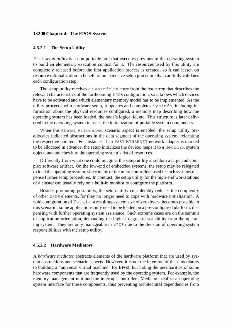
132� Chapter 4: The EPOS System
4.5.2.1 The Setup Utility
EPOSsetup utilityis a non-portable tool that executes previous to the operating systemto build an elementary execution context for it. The resources used by this utility arecompletely released before the first application process is created, so it can lessen onresource rationalization in benefit of an extensive setup procedure that carefully validateseach configuration step.
The setup utility receives aSysInfo structure from thebootstrapthat describes therelevant characteristics of the forthcoming EPOSconfiguration, so it knows which deviceshave to be activated and which elementary memory model has to be implemented. As theutility proceeds with hardware setup, it updates and completesSysInfo , including in-formation about the physical resources configured, a memory map describing how theoperating system has been loaded, the node’s logical id, etc. This structure is later deliv-ered to the operating system to assist the initialization of portable system components.
When theAhead_Allocated scenario aspect is enabled, the setup utility pre-allocates indicated abstractions in the data segment of the operating system, relocatingthe respective pointers. For instance, if an FAST ETHERNET network adapter is markedto be allocated in advance, the setup initializes the device, maps it to aNetwork systemobject, and attaches it to the operating system’s list of resources.
Differently from what one could imagine, the setup utility is seldom a large and com-plex software artifact. On the low-end of embedded systems, the setup may be relegatedto load the operating system, since many of the microcontrollers used in such systems dis-pense further setup procedures. In contrast, the setup utility for the high-end workstationsof a cluster can usually rely on a built-in monitor to configure the platform.
Besides promoting portability, the setup utility considerably reduces the complexityof other EPOSelements, for they no longer need to cope with hardware initialization. Avoid configuration of EPOS, i.e. a resulting system size of zero bytes, becomes possible inthis scenario: some applications only need to be loaded on a pre-configured platform, dis-pensing with further operating system assistance. Such extreme cases are on the summitof application-orientation, demanding the highest degree of scalability from the operat-ing system. They are only manageable in EPOSdue to the division of operating systemresponsibilities with the setup utility.
4.5.2.2 Hardware Mediators
A hardware mediatorabstracts elements of the hardware platform that are used by sys-tem abstractions and scenario aspects. However, it is not the intention of these mediatorsto building a “universal virtual machine” for EPOS, but hiding the peculiarities of somehardware components that are frequently used by the operating system. For example, thememory management unit and the interrupt controller. Mediators realize an operatingsystem interface for these components, thus preventing architectural dependencies from
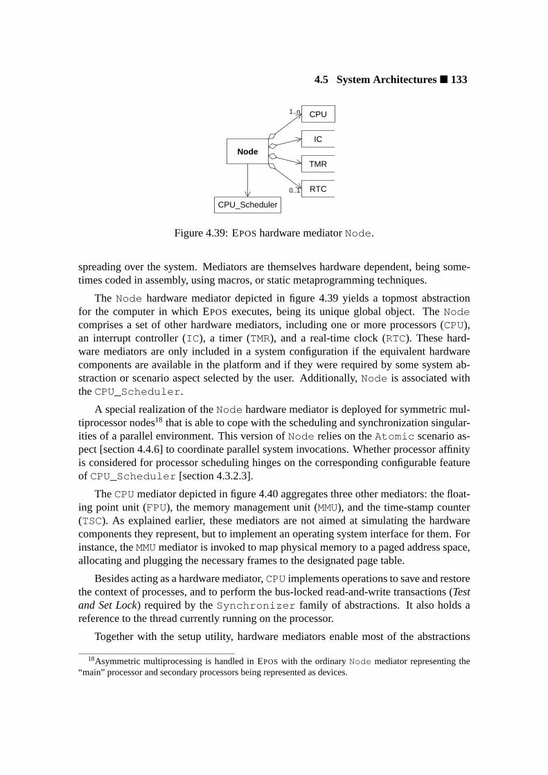
4.5 System Architectures� 133
IC
RTC
CPU
Node
TMR
CPU_Scheduler
1..n
0..1
Figure 4.39: EPOShardware mediatorNode.
spreading over the system. Mediators are themselves hardware dependent, being some-times coded in assembly, using macros, or static metaprogramming techniques.
The Node hardware mediator depicted in figure 4.39 yields a topmost abstractionfor the computer in which EPOS executes, being its unique global object. TheNodecomprises a set of other hardware mediators, including one or more processors (CPU),an interrupt controller (IC ), a timer (TMR), and a real-time clock (RTC). These hard-ware mediators are only included in a system configuration if the equivalent hardwarecomponents are available in the platform and if they were required by some system ab-straction or scenario aspect selected by the user. Additionally,Node is associated withtheCPU_Scheduler .
A special realization of theNode hardware mediator is deployed for symmetric mul-tiprocessor nodes18 that is able to cope with the scheduling and synchronization singular-ities of a parallel environment. This version ofNode relies on theAtomic scenario as-pect [section 4.4.6] to coordinate parallel system invocations. Whether processor affinityis considered for processor scheduling hinges on the corresponding configurable featureof CPU_Scheduler [section 4.3.2.3].
TheCPUmediator depicted in figure 4.40 aggregates three other mediators: the float-ing point unit (FPU), the memory management unit (MMU), and the time-stamp counter(TSC). As explained earlier, these mediators are not aimed at simulating the hardwarecomponents they represent, but to implement an operating system interface for them. Forinstance, theMMUmediator is invoked to map physical memory to a paged address space,allocating and plugging the necessary frames to the designated page table.
Besides acting as a hardware mediator,CPUimplements operations to save and restorethe context of processes, and to perform the bus-locked read-and-write transactions (Testand Set Lock) required by theSynchronizer family of abstractions. It also holds areference to the thread currently running on the processor.
Together with the setup utility, hardware mediators enable most of the abstractions
18Asymmetric multiprocessing is handled in EPOS with the ordinaryNode mediator representing the“main” processor and secondary processors being represented as devices.
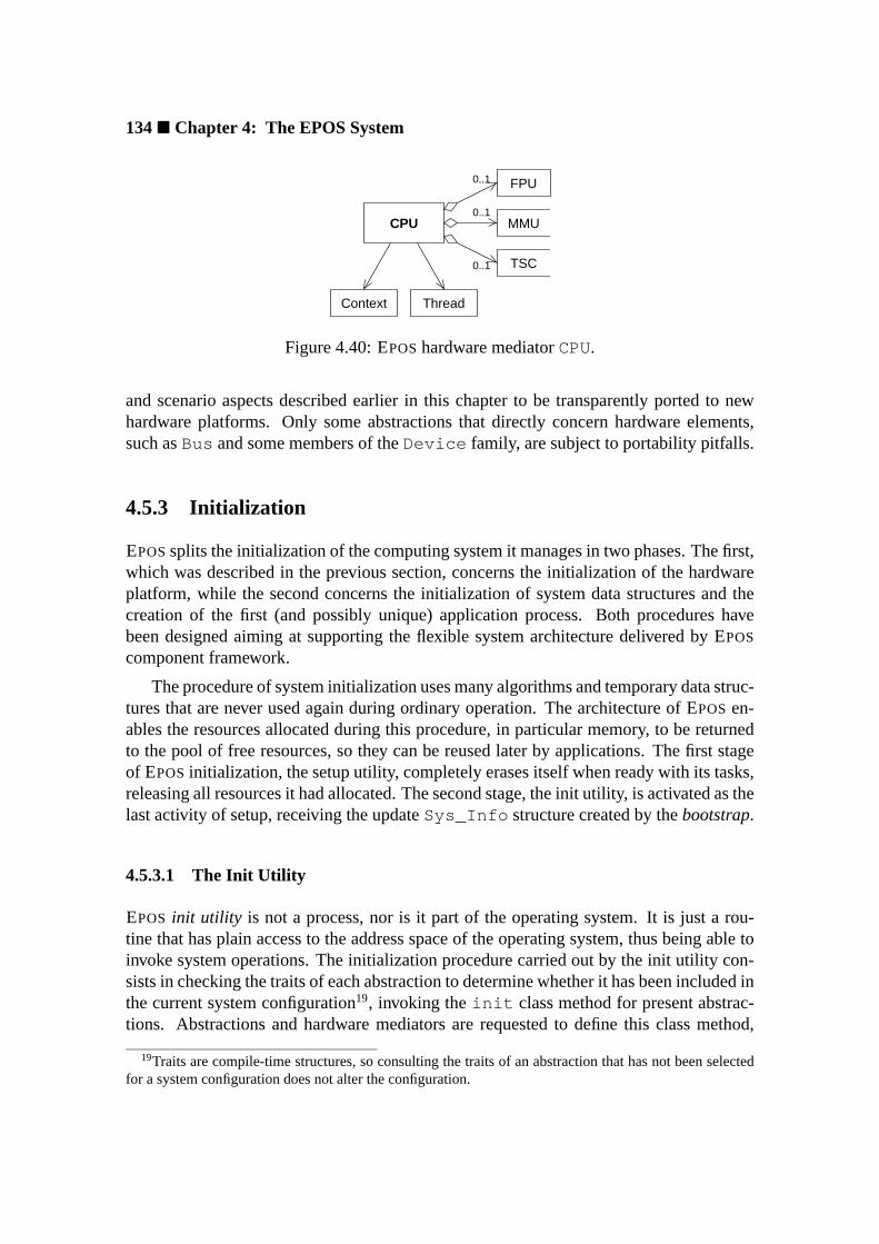
134� Chapter 4: The EPOS System
CPU
FPU
MMU
TSC
ThreadContext
0..1
0..1
0..1
Figure 4.40: EPOShardware mediatorCPU.
and scenario aspects described earlier in this chapter to be transparently ported to newhardware platforms. Only some abstractions that directly concern hardware elements,such asBus and some members of theDevice family, are subject to portability pitfalls.
4.5.3 Initialization
EPOSsplits the initialization of the computing system it manages in two phases. The first,which was described in the previous section, concerns the initialization of the hardwareplatform, while the second concerns the initialization of system data structures and thecreation of the first (and possibly unique) application process. Both procedures havebeen designed aiming at supporting the flexible system architecture delivered by EPOS
component framework.
The procedure of system initialization uses many algorithms and temporary data struc-tures that are never used again during ordinary operation. The architecture of EPOSen-ables the resources allocated during this procedure, in particular memory, to be returnedto the pool of free resources, so they can be reused later by applications. The first stageof EPOSinitialization, the setup utility, completely erases itself when ready with its tasks,releasing all resources it had allocated. The second stage, the init utility, is activated as thelast activity of setup, receiving the updateSys_Info structure created by thebootstrap.
4.5.3.1 The Init Utility
EPOS init utility is not a process, nor is it part of the operating system. It is just a rou-tine that has plain access to the address space of the operating system, thus being able toinvoke system operations. The initialization procedure carried out by the init utility con-sists in checking the traits of each abstraction to determine whether it has been included inthe current system configuration19, invoking theinit class method for present abstrac-tions. Abstractions and hardware mediators are requested to define this class method,
19Traits are compile-time structures, so consulting the traits of an abstraction that has not been selectedfor a system configuration does not alter the configuration.

4.5 System Architectures� 135
application
aheadalloc.EPOS
logical
memory
devices
setup initinit
aheadalloc.EPOS
memory
Sys_Info
boot image
setup utilityboot
memory
devicesphysical
Sys_Info
boot image
Figure 4.41: An overview of EPOSinitialization.
which is responsible for initializing associated operating system structures. Besides hav-ing access to the traits of the abstraction it initializes, class methodinit also receivestheSys_Info structure as parameter, so it can consult the system description left by thesetup utility. Furthermore, these class methods undergo a special link-editing process thatcauses them to be linked to the init utility rather than the operating system.
After having invoked theinit class method for all present abstractions, the init utilityinvokes EPOSoperations, which by now are fully operational, to create the first process.If the dedicated application running on EPOS is executed by a single process (per node),then the process created by the init utility is the application’s unique process. Otherwise,this process is aloader that subsequently creates application processes in a multitaskingenvironment. Before finishing, init releases all resources it had allocated, leaving EPOS
alone with application processes.
An overview of EPOS initialization is depicted in figure 4.41. After loading the bootimage, which includes a preliminary system description (Sys_Info ), the bootstrap in-vokes the setup utility to configure the hardware platform. Considering the specificationsin Sys_Info , the setup utility builds an elementary memory model, configures requireddevices, loads EPOS, pre-allocatesAhead_Allocated abstractions, loads the init util-ity, and activates it. The init utility, in turn, invokes theinit class method of everyabstraction included in the system to initialize its logical structure. It finishes loading theexecutable provided in the boot image to create the first process.
4.5.3.2 System Organization
The initialization procedure described above causes EPOS to assume one of the orga-nizations depicted in figure 4.42. If theembedded-in-the-applicationorganization is to

136� Chapter 4: The EPOS System
be accomplished, the setup utility arranges for a single address space that is shared bythe operating system and the application process. Hence, this organization implies thesingle-tasking environment realized by theExclusive member of theTask family.
devdevEPOS
ROI
−kernelµ
devdev
loader ROI
application
application
Embedded
application
devdev
EPOS
(a) (b)
Figure 4.42: EPOSorganizations: (a) embedded-in-the-application and (b)µ-kernel.
Though sharing the same address space, application and operating system are notlinked together when the embedded-in-the-application organization is selected. Instead,the application is supplied a copy of the operating system’s symbol table during linkage,thus enabling it to invoke system operations via ordinary procedure calls20. This designdecision enables the setup utility to adopt an operating system loading procedure that iscommon to both organizations, embedded-in-the-application andµ-kernel.
Furthermore, avoiding linking operating system and applications together enables theportion of the address space in which the operating system resides to be protected againstmisleading applications. This is useful, even in single-tasking environments, to assistdebugging applications. If the hardware platform permits, EPOScode segment is markedexecute-only, while its data segment is marked accessible only from the code segment.Access violations regarding this scheme are caught and can be monitored activating theDebugged scenario aspect.
If EPOSis configured as aµ-kernel, the setup utility prepares two address spaces: onefor the kernel and one for the first process. In this case, the init utility is temporarilyloaded in the address space of the kernel. With theµ-kernel organization, EPOSfeaturesa system-call interface that is used by applications to interact with system abstractions.This interface implies in theRemote scenario aspect being enabled. The first processin this organization is the application loader, which additionally starts the ROI server iftheGlobal_Id scenario aspect is enabled. Shared devices are delivered through deviceservers, which are also created by the loader. Since the loader is an ordinary user-levelprocess, no modifications in the initialization procedure are necessary to accomplish thismodel.
20EPOScomponent framework metaprogram is processed in the context of applications, therefore a frac-tion of the operating system will always be embedded in the application. Moreover, some elementarysystem operations may completely embed in the application (through inlining).

4.6 Automatic Configuration� 137
4.6 Automatic Configuration
EPOS application-oriented system design enables it to be tailored to match the require-ments of particular applications. By specifying configuration keys, users select the sys-tem abstractions, scenario adapters, and hardware mediators that are necessary to supporta given application. Composition rules facilitate the task of tailoring EPOS, allowing usersto specify a reduced number of configuration keys that are expanded in a coherent sys-tem configuration. Moreover, a user-friendly visual tool can be deployed to carry out thismanual configuration process.
However, EPOScomprises hundreds of configurable elements. Delivering applicationprogrammers such a massive repository of components and a mechanism to select andplug them in a component framework may be inadequate. Users can miss the most ap-propriate system configuration for a given application simply because there are excessivealternatives. Even if composition rules allow them to specify a reduced number of con-figurable elements, it is possible that significant elements will be relegated to inadequatedefault configurations. Fortunately, application-oriented system design makes it possibleto automate the system configuration process to reduce the occurrence of such incidents.
For a component-based operating system like EPOS, accomplishing an automated“system factory” is mainly a matter of understanding application requirements. The wayEPOSassociates configuration keys to abstraction interfaces allows application program-mers to specify application requirements about the operation system simply by writingdown system invocations. If programmers are not sure about which member of a familyof abstractions should be used in a situation, or if they realize the selection may need tobe changed in the future, they can use the family’s inflated interface instead. Afterwards,the application can be submitted to a pipeline of tools that will tailor EPOSto fit it.
A schematic representation of the process of automatic configuring EPOSis presentedin figure 4.43. The first step consists in performing a syntactical analysis of the applica-tion’s source code to identifywhichsystem abstractions have been invoked by the appli-cation andhow they have been invoked. This step is carried out by theanalyzer, whichgenerates a preliminary configuration blueprint consisting of family’s (inflated) and mem-ber’s interfaces.
The preliminary configuration blueprint produced by the analyzer is subsequentlypassed to theconfigurator. This tool consults the catalog of composition rules and thelist of abstractions to refine the configuration blueprint. During this refinement, someinflated interfaces are bound to satisfy dependencies and constraints. Those that remainunbound are subsequently bound to their “lightest” realizations. The output of this tool isa table of configuration keys that shapes a framework for the desired EPOSconfiguration.
In order to support the proposed automatic configuration scheme, EPOSabstractionsand scenario aspects have been sorted in a cost model corresponding to their intrinsicoverhead. This ordering is revealed by the sequence in which abstractions and scenarioaspects have been introduced in their families along this chapter, i.e. theExclusive
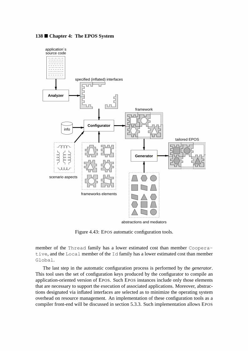
138� Chapter 4: The EPOS System
Analyzer
Generator
Configurator
application´ssource code
info
scenario aspects
framework
tailored EPOS
specified (inflated) interfaces
frameworks elements
abstractions and mediators
Figure 4.43: EPOSautomatic configuration tools.
member of theThread family has a lower estimated cost than memberCoopera-tive , and theLocal member of theId family has a lower estimated cost than memberGlobal .
The last step in the automatic configuration process is performed by thegenerator.This tool uses the set of configuration keys produced by the configurator to compile anapplication-oriented version of EPOS. Such EPOS instances include only those elementsthat are necessary to support the execution of associated applications. Moreover, abstrac-tions designated via inflated interfaces are selected as to minimize the operating systemoverhead on resource management. An implementation of these configuration tools as acompiler front-end will be discussed in section 5.3.3. Such implementation allows EPOS
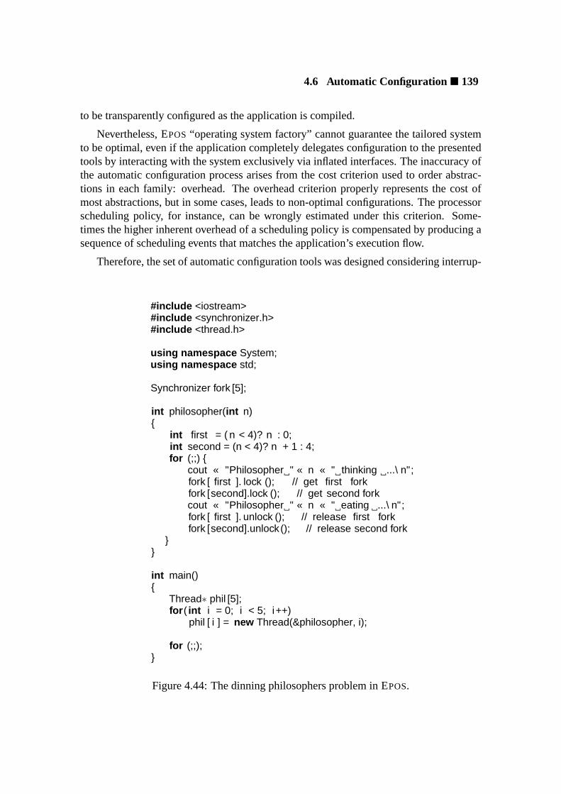
4.6 Automatic Configuration� 139
to be transparently configured as the application is compiled.
Nevertheless, EPOS“operating system factory” cannot guarantee the tailored systemto be optimal, even if the application completely delegates configuration to the presentedtools by interacting with the system exclusively via inflated interfaces. The inaccuracy ofthe automatic configuration process arises from the cost criterion used to order abstrac-tions in each family: overhead. The overhead criterion properly represents the cost ofmost abstractions, but in some cases, leads to non-optimal configurations. The processorscheduling policy, for instance, can be wrongly estimated under this criterion. Some-times the higher inherent overhead of a scheduling policy is compensated by producing asequence of scheduling events that matches the application’s execution flow.
Therefore, the set of automatic configuration tools was designed considering interrup-
#include <iostream>#include <synchronizer.h>#include <thread.h>
using namespace System;using namespace std;
Synchronizer fork [5];
int philosopher(int n){
int first = ( n < 4)? n : 0;int second = (n < 4)? n + 1 : 4;for (;;) {
cout « "Philosopher " « n « " thinking ...\ n";fork [ first ]. lock (); // get first forkfork [second].lock (); // get second forkcout « "Philosopher " « n « " eating ...\ n";fork [ first ]. unlock (); // release first forkfork [second].unlock(); // release second fork
}}
int main(){
Thread∗ phil [5];for ( int i = 0; i < 5; i++)
phil [ i ] = new Thread(&philosopher, i);
for (;;);}
Figure 4.44: The dinning philosophers problem in EPOS.

140� Chapter 4: The EPOS System
tions after each phase, so users can invoke the manual configuration tool to check andmodify the automatically generated configuration before it is submitted to the generator.
For an example of automatic system configuration, the program in figure 4.44 willbe considered. This is a valid EPOS implementation of the classicdining philosophersproblem [Dij71]. It requires three system abstractions:Thread , Synchronizer , andConsole . The analyzerwould identify these families, as well as the scope in whichthey were used, and output a table with the signatures of used operations. Signatures areknown by the analyzer from the interfaces supplied in the system header files included.The syntactical analysis of this program, ignoring the complexiostream header, wouldlook like the following:
global {System::Interface ::Synchronizer::Synchronizer(void );System::Interface ::Synchronizer::lock(void );System::Interface ::Synchronizer::unlock(void );
}
main {System::Interface ::Thread::Thread(int (∗)( int ), int )
}
The analysis report reveals that objects of typeSynchronizer have been createdin the global scope using the default constructor, and that operationslock andunlockhave been invoked on them. It also reveals that objects of typeThread have been createdin the scope of functionmain using a constructor that takes a pointer to a function andan integer as parameter.
The configuratorwould process this information considering the catalog of compo-sition rules and the list of system abstractions. This would lead theSynchronizerinflated interface to be bound toMutex , for it supplies the required operations. Evenif Semaphore had declared a default constructor and operationslock andunlockas synonyms forp andv , thus emulating aMutex , the cost ordering would have madeMutex the best choice.
The selection of a realization for theThread inflated interface would be based ona special composition rule that requires methodpass , which hands processor controlover another thread, to be explicitly invoked in order that realizationCooperative isselected. Since theExclusive realization ofThread does not feature thread creation,memberConcurrent would be selected.
However, theConcurrent thread implies in theCPU_Scheduler abstraction,which in this case would adoptFCFSas the scheduling policy, for it incurs in the lowestoverhead. Nonetheless, this decision would only be adequate if the application is executedin a node with five or more processors. Otherwise, some philosophers would never exe-cute. This reveals the limitations of EPOSautomatic configuration. Though the number

4.7 Summary� 141
of processors on each node is available to configuration tools, the decision of bypassingthe cost model to select a different scheduling policy cannot be taken automatically. Ifless than five processors are available in the indicated node, the user would either have tomanually correct the configuration, or modify the ordering of scheduling policies in thecost model to define another default.
4.7 Summary
EPOS(Embedded Parallel Operating System) is an experimental application-oriented op-erating system developed in the scope of this dissertation to validate concepts and tech-niques of application-oriented system design. The domain envisioned by EPOS is thatof high-performance dedicated computing, which comprises applications that, besidesrunning with exclusivity on the respective platforms, require an efficient management ofresources. This domain comprises mainly embedded and parallel applications.
In order to cope with the steady evolution of the envisioned domain, EPOSestablishedan open and continuous domain analysis process that allows new entities to be includedin the design as they are identified in the domain. Domain entities were modeled aimingat high scalability and reusability, so that EPOScan be tailored to particular applications.Abstractions are mostly independent of each other, of execution scenario aspects, andof component frameworks. Consequently, they can be extensively reused in a variety ofscenarios. Furthermore, EPOS component framework can be adjusted to accommodateforthcoming abstractions, or to build particular software architectures, without affectingexisting abstractions.
EPOS captures the entities in the domain of high-performance dedicated computingwith application-oriented abstractions that realize mechanisms concerning the manage-ment of memory, processes, coordination, communication, time, and I/O. Besides, aremote object invocation mechanism allows for external abstractions, such as files andgraphical display, to be transparently accessed. Entities with strong architectural depen-dency, such as node and CPU, were separately modeled as non-portable hardware media-tors that realize a portable operating system interface.
EPOSmodels the following properties of domain entities as scenario aspects: identi-fication, sharing, allocation, protection, timing, atomicity, remote invocation, debugging,and profiling. An execution scenario for abstractions is shaped by combining suitablescenario aspects, which are transparently applied to abstractions via scenario adapters.
EPOS component framework captures elements of reusable system architectures,defining how abstractions can be composed. It was modeled as a collection of interre-lated scenario adapters that build a “socket board” for system abstractions and scenarioaspects, which are “plugged” via inflated interface binding. The framework is realized bya static metaprogram and a set of externally defined composition rules. The metaprogramis responsible for adapting abstractions to the selected execution scenario and arranging

142� Chapter 4: The EPOS System
them together during the compilation of an application-oriented instance of EPOS, whilethe rules coordinate the operation of the metaprogram, specifying constraints and depen-dencies for the composition of abstractions.
The scalable software architecture accomplished by the component framework is sus-tained by thesetupandinit utilities. The former isolates architectural dependencies con-cerning hardware initialization, while the latter isolates system initialization procedures.In cooperation with the framework metaprogram, these utilities are able to deliver anEPOSinstance either as aµ-kernel or fully embed it in a single-tasked application.
EPOSdesign allows for automatic configuration and generation. Abstraction and fam-ily (inflated) interfaces referred to by an application can be collected by EPOSanalyzerto yield a blueprint for the system that has to be generated. This blueprint is subsequentlyprocessed by EPOS configurator, which consults a catalog of composition rules and alist of existing system abstractions to configure the component framework according toapplication needs. At last, EPOSgeneratorcompiles an instance of EPOS including thenecessary abstractions, mediators, and scenario aspects.
Chapter 5
EPOS Implementation for theSNOW Cluster
The EPOSsystem described in chapter 4 illustrates the deployment of application-orientedsystem design to engineer the domain of high-performance dedicated computing. Thatcase study helped to corroborate the concepts and techniques of application-oriented sys-tem design proposed in chapter 3. However, if EPOS is to be accepted as a validation ofapplication-oriented system design, its design must also be validated. Although many ofEPOS design decisions have been well substantiated, a design can hardly be positivelyevaluated before it is implemented to a significant extent. Therefore, a prototype imple-mentation of EPOSfor the SNOW cluster was carried out in the scope of this dissertation.
5.1 Why a Cluster of Workstations?
The idea of clustering commodity workstations as a cost-effective alternative to expen-siveMassively Parallel Processors(MPP) has now been explored for quite a long time.Perhaps one of the first approaches has been the one in which the idle time of ordinaryworkstations interconnected in aLocal Area Network(LAN) was collected to form acomputational resource pool that could be used to support the execution of parallel ap-plications [HCG+82, Che84]. This idea has been around for almost as long as the LANitself and undoubtedly helped to open the way for cluster computing. Nowadays, how-ever, cluster computing is better associated with a pile of workstations interconnected in aSystem Area Network(SAN) and completely dedicated to support the execution of parallelapplications. During this natural evolution towards performance, cluster computing hasreshaped the concept of commodity computing by triggering the migration of softwareand hardware concepts from the supercomputer environment to the desktop.
Undoubtedly, cost-effectiveness has been a key factor to boost the utilizationof clusters of workstations to support high-performance computing. However,

144� Chapter 5: EPOS Implementation for the SNOW Cluster
price/performance is not a metric when the problem to be solved, i.e. the parallel ap-plication to be executed, demands performance figures that cannot be supplied by a cost-effective cluster. That these FLOP famished applications are there, no one questions, butthe suggestion that an MPP is the only way to appease them, is increasingly controver-sial. Recent developments suggest that clusters are going, in the short term, to overcomeMPPs also in absolute performance [TFC00, CPL+97]. This optimism is not accidental—it arises from simple market laws that favor large-scale production. Improving perform-ance of computational systems demands large efforts on engineering and manufacturing,which are usually achieved at a very high cost. While MPPs have to share these costsamong a few produced units, clusters can share them with the huge workstation market.This phenomenon has been slowing the development of custom hardware, in favor ofcommodity components, in such a way as to indicate that both technologies, MPPs andclusters, are about to merge. The Intel ASCI Red MPP [San01] is a good example for thismerge: its processing elements are ordinary Intel Pentium Pro microprocessors normallyfound in PCs, and the whole machine has only two non-commodity components in theinterconnection system.
Although the commodity workstation hardware scene looks bright, the same cannotbe stated about commodity software. The run-time support systems running on ordi-nary workstations have not been designed with parallel computing in mind and usuallyfail to deliver the functionality needed to execute a parallel application. The commoditysolution to this problem is to add a middleware layer, so that features like location trans-parency, remote invocation, and synchronization are appended to the system. However,this configuration often fails to achieve the performance level demanded by the parallelapplication [NAS97, MT00].
Indeed, the need for specialized run-time support systems in order to support paral-lel computing on clusters of workstations has already been recognized by the fraction ofthe cluster computing community compromised with high-performance [ABLL92, Fel92,BRB98]. In this scene, modifications in the operating system kernel, customizationsin run-time support libraries, and specialized middleware implementations are common-practice, with user-level communication being a frequently explored optimization. Thiscan be observed in projects like U-NET at Cornell University [WBvE96], FAST MES-SAGES (FM) at the University of Illinois [PKC97], PM at the Real World ComputingPartnership [THIS97], BASIC INTERFACE FORPARALLELISM (BIP) at the University ofLyon [PT98], and others.
However, run-time support system specializations for cluster computing are usuallynot customizable with regard to application requirements, focusing on improving per-formance by exploring particular architectural features. Especially regarding communi-cation, most solutions comprise a single protocol, disregarding the particular characteris-tics of each application. In contrast, EPOSwas designed to be customized according toapplication needs, delivering abstractions that can be adjusted and combined to producea large variety of run-time systems. For example, EPOScommunication subsystem [sec-

5.2 The SNOW Cluster� 145
tion 4.3.4] comprises six families of abstractions and a number of configurable featuresthat can be arranged to deliver applications a tailored communication system.
5.2 The SNOW Cluster
The SNOW cluster was assembled in 1997 at the Research Institute for Computer Archi-tecture and Software Engineering (FIRST) of the German National Research Center forInformation Technology (GMD). The cluster consists of 24 processing nodes intercon-nected with a high-speed network and connected to a server through a service network.These are all off-the-shelf components that have been separately acquired and locallyassembled by the institute staff.
A sketch of the SNOW cluster from the perspective of EPOSis presented in figure 5.1.The server acts as a front-end to the cluster, from which parallel applications are startedand monitored. While running EPOS, processing nodes are entirely managed from theserver, which triggers a remote boot procedure to start up a tailored EPOSfor each appli-cation session. The server also provides parallel applications running on processing nodeswith a persistent storage facility.
EPOS
application
EPOS
application
EPOSLINUX
manager ...Node 0 Node 23
Internet
service network
high−speed network
Server
FS
Figure 5.1: The SNOW cluster from the perspective of EPOS.
5.2.1 Processing Nodes
SNOW processing nodes are diskless workstations, each comprising one or two IntelP6 processors, main memory, and network interface cards (NIC) for the computing(MYRINET) and service (FAST ETHERNET) networks. A schematic of a SNOW nodefocusing on hardware components that are significant to EPOSis shown in figure 5.2.
Every hardware platform has its highs and lows. When used for a purpose other thanthe originally conceived, it is natural that lows become more noticeable. Commodityworkstations are not constructed to support parallel computing and, when used for thispurpose, often fail to exhibit the properties anticipated by applications. Before beginning

146� Chapter 5: EPOS Implementation for the SNOW Cluster
cache
TSCMMUFPU
ix86MMUFPU
ix86TSC
cache
memory
TMRIC
RTC
myrinet
ethernet
PCI
Figure 5.2: A SNOW node from the perspective of EPOS.
the implementation of EPOSfor the SNOW cluster, a series of experiments has been per-formed in order to identify hardware limitations concerning high-performance computingthat could be reduced by proper operating system design. These experiments identifiedtwo major limitations:
1. Low memory bandwidth: SNOW nodes, like most iX86-based workstations, areequipped with low bandwidth memory subsystems. This deficiency is usually notperceptible to the interactive applications that are traditionally executed on suchplatforms thanks to a high-bandwidth cache mechanism that hides main memorylatency. Nevertheless, a parallel application performing short computation cycleson large data sets can easily overflow such mechanism, leading the processor towait for the memory subsystem.
2. Interconnect on I/O bus: in contrast to MPP nodes, which usually integrate inter-connect mechanisms to the processor/memory path, clusters of commodity work-stations rely on ordinary network interface cards plugged in the I/O bus (figure 5.2).As consequence, the path to the network is lengthened and the overhead on inter-node communication increased. In the particular case of SNOW, the data transferrate between main memory and the MYRINET adapter is lower than between twoMYRINET NICs on different nodes.
There is not much an operating system can do to overcome the first limitation. Caringfor cache-aligned memoryallocationcould help, but the operating system cannot enforcecache-aligned memoryaccess(a compiler could). Regarding the second limitation, how-ever, the experiments conducted with SNOW helped to design a pipelined communicationsubsystem that is able to hide a significant part of the latency induced by the hardwarearchitecture. This mechanism will be discussed later in section 5.3.1.
5.2.2 Interconnects
SNOW processing nodes are interconnected by two networks: a service network used forinteractions with the server, and a computing network used for message exchange be-
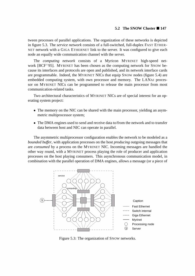
5.2 The SNOW Cluster� 147
tween processes of parallel applications. The organization of these networks is depictedin figure 5.3. Theservice networkconsists of a full-switched, full-duplex FAST ETHER-NET network with a GIGA ETHERNET link to the server. It was configured to give eachnode an equally wide communication channel with the server.
The computing networkconsists of a Myricon MYRINET high-speed net-work [BCF+95]. MYRINET has been chosen as the computing network for SNOW be-cause its interfaces and protocols are open and published, and its network interface cardsare programmable. Indeed, the MYRINET NICs that equip SNOW nodes (figure 5.4) areembedded computing system, with own processor and memory. The LANAI proces-sor on MYRINET NICs can be programmed to release the main processor from mostcommunication-related tasks.
Two architectural characteristics of MYRINET NICs are of special interest for an op-erating system project:
• The memory on the NIC can be shared with the main processor, yielding an asym-metric multiprocessor system;
• The DMA engines used to send and receive data to/from the network and to transferdata between host and NIC can operate in parallel.
The asymmetric multiprocessor configuration enables the network to be modeled as abounded buffer, with application processes on the hostproducingoutgoing messages thatareconsumedby a process on the MYRINET NIC. Incoming messages are handled theother way round, with a MYRINET process playing the role of producer and applicationprocesses on the host playing consumers. This asynchronous communication model, incombination with the parallel operation of DMA engines, allows a message (or a piece of
Processing node
Server
Switch internal
Giga Ethernet
Myrinet
Fast Ethernet
S
S
Caption
computing
service
Figure 5.3: The organization of SNOW networks.
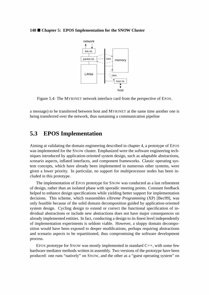
148� Chapter 5: EPOS Implementation for the SNOW Cluster
link int.
packet int.
LANai
host int.
memory
DMA
network
host
DMA
Figure 5.4: The MYRINET network interface card from the perspective of EPOS.
a message) to be transferred between host and MYRINET at the same time another one isbeing transferred over the network, thus sustaining a communication pipeline
5.3 EPOS Implementation
Aiming at validating the domain engineering described in chapter 4, a prototype of EPOS
was implemented for the SNOW cluster. Emphasized were the software engineering tech-niques introduced by application-oriented system design, such as adaptable abstractions,scenario aspects, inflated interfaces, and component frameworks. Classic operating sys-tem concepts, which have already been implemented in numerous other systems, weregiven a lower priority. In particular, no support for multiprocessor nodes has been in-cluded in this prototype.
The implementation of EPOSprototype for SNOW was conducted as a last refinementof design, rather than an isolated phase with sporadic meeting points. Constant feedbackhelped to enhance design specifications while yielding better support for implementationdecisions. This scheme, which reassembleseXtreme Programming(XP) [Bec99], wasonly feasible because of the solid domain decomposition guided by application-orientedsystem design. Cycling design to extend or correct the functional specification of in-dividual abstractions or include new abstractions does not have major consequences onalready implemented entities. In fact, conducting a design to its finest level independentlyof implementation experiments is seldom viable. However, a sloppy domain decompo-sition would have been exposed to deeper modifications, perhaps requiring abstractionsand scenario aspects to be repartitioned, thus compromising the software developmentprocess.
EPOSprototype for SNOW was mostly implemented in standard C++, with some fewhardware mediator methods written in assembly. Two versions of the prototype have beenproduced: one runs “natively” on SNOW, and the other as a “guest operating system” on

5.3 EPOS Implementation� 149
L INUX . From the point of view of applications, both versions are functionally equivalent,though the LINUX -guest implementation suffers performance impairments due to LINUX
memory and process management strategies. Specifically, there is no way to disable mul-titasking and scheduling on UNIX -like systems, consequently affecting the execution ofdedicated applications that do not need such features.
Several of the EPOS abstractions described in section 4.3 have been implementedfor SNOW, including representatives of all modeled families. Particularly interesting inthe context of application-orientation, were those minimalist abstractions unavailable ingeneral-purpose operating systems, such as theFlat_Address_Space , theExclu-sive_Task , and theExclusive_Thread .
The Flat_Address_Space has a practically empty implementation, since theconfiguration of the iX86’s MMU to simulate a flat address space is performed by thesetup utility1. The abstraction only features operations to assert the status of the mem-ory subsystem and to modifying memory-mapping modes (through the methods of theMMUhardware mediator). TheExclusive_Task is also mostly realized by the setuputility, which loads the task’s code segment in a ready-only portion of the address space,assigning the remaining memory to the task’s data segment.
TheExclusive_Thread implementation consists basically of status and termina-tion operations. If theAlarm abstraction is not explicitly instantiated by the application,timer interrupts remain disabled, since processor scheduling is not necessary for this ab-straction2. Together withFlat_Address_Space andExclusive_Task , Exclu-sive_Thread is able to produce an EPOS instance of size zero: after hardware andsystem initialization, absolutely all resources are delivered to the application process.
The decomposition guided by application-oriented system design resulted in relativelysimple implementations even for EPOSmost complex abstractions. For instance, a largenumber of entities pertaining the implementation of thePaged_Address_Space ,Mutual_Task , and Concurrent_Thread abstractions have been separatelyimplemented as hardware mediators and scenario aspects. Implementing thePaged_Address_Space abstraction without having to consider the idiosyncrasiesof iX86’s MMU (and vice-versa) was undoubtedly more effective than implementing amonolithic abstraction.
EPOSscenario aspects [section 4.4] have been modeled relying on the ability ofsce-nario adaptersto autonomously enforce ascenario(i.e. a composition of structural andbehavioral scenario aspects) to abstractions, thus eliminating eventual dependencies fromthe component framework. Consequently, scenario aspects could be implemented asautonomous objects that are aggregated to form aScenario object. This is subse-quently applied to abstractions by theAdapter framework element (see figure 4.33 insection 4.5.1).
1Completely disabling the MMU of a iX86 processor is not possible, so the setup utility has to arrangefor a mapping in which logical and physical addresses match.
2Time operations performed withClock andChronometer do not depend from timer interrupts.

150� Chapter 5: EPOS Implementation for the SNOW Cluster
Accomplishing an implementation of EPOScomponent framework metaprogram [sec-tion 4.5.1] that respect the autonomy of system abstractions and scenario aspects, i.e. thatdoes not require them to incorporate specific framework elements, was the most time-demanding activity during the implementation of EPOSprototype. A precise realizationof the design described in section 4.5.1 as a set of C++ templates could only be ac-complished after a long streamline process. This process exposed many pitfalls of staticmetaprogramming in C++, especially concerning maintainability3. Achieving the ex-pected functionality was not problematic, but the first versions of the metaprogram werealmost unintelligible.
Nevertheless, the resultant framework metaprogram, besides being able to handle in-dependently defined abstractions and scenario aspects, has a null intrinsic overhead andis relatively easy to maintain.
5.3.1 The Myrinet Network Abstraction
A distinguished abstraction implemented for the SNOW cluster is theMyrinet mem-ber of theNetwork family. This abstraction was firstly implemented for the guest ver-sion of EPOS focusing on pipelining the communication system [Tie99]. Subsequently,a native version emphasizing aspects of application-oriented system design was con-ducted [FTSP00].
A design diagram of theMyrinet abstraction is depicted in figure 5.5.Myrinetuses theMyrinet_NIC member of theDevice family to realize the uniform inflatedinterface of theNetwork family. TheMyrinet_NIC device abstraction deploys mech-anisms provided by its family common package to map the control registers and the mem-ory of a MYRINET NIC to the address space of the main processor. In this way, thestate of aMyrinet_NIC instance matches the state of the corresponding physical NIC4.Myrinet subsequently usesMyrinet_NIC to realize a member of theNetwork fam-ily of abstractions, defining methods to send and receive packets of data to peer nodes onthe MYRINET system area network.
A configurable feature is more than a flag to control the inclusion of an optional fam-ily feature; it also designates a generic implementation of the feature that can be reusedby family members. With regard to MYRINET, theordering configurable feature ispermanently enabled, since the source routing strategy used by MYRINET implicitly en-sures in-order delivery. However, the generic implementations of configurable featuresmulticast andbroadcast would be reused, since MYRINET does not support themby design.
Nevertheless, a MYRINET NIC has its own processor and could itself implement
3The framework metaprogram is not exposed to end users.4The setup utility pre-allocates one instace ofMyrinet_NIC for each MYRINET NIC installed in the
node.
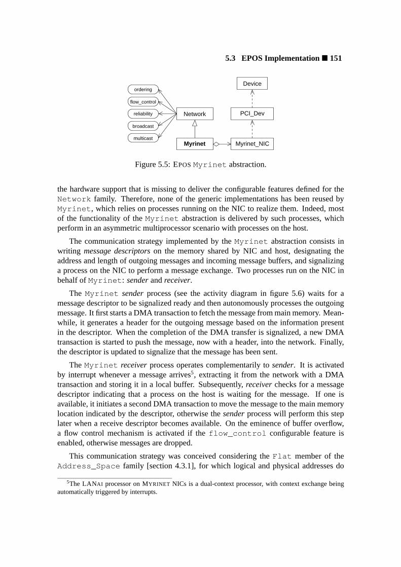
5.3 EPOS Implementation� 151
Device
Myrinet
PCI_Dev
Myrinet_NIC
Network
broadcast
ordering
flow_control
reliability
multicast
Figure 5.5: EPOSMyrinet abstraction.
the hardware support that is missing to deliver the configurable features defined for theNetwork family. Therefore, none of the generic implementations has been reused byMyrinet , which relies on processes running on the NIC to realize them. Indeed, mostof the functionality of theMyrinet abstraction is delivered by such processes, whichperform in an asymmetric multiprocessor scenario with processes on the host.
The communication strategy implemented by theMyrinet abstraction consists inwriting message descriptorson the memory shared by NIC and host, designating theaddress and length of outgoing messages and incoming message buffers, and signalizinga process on the NIC to perform a message exchange. Two processes run on the NIC inbehalf ofMyrinet : senderandreceiver.
The Myrinet senderprocess (see the activity diagram in figure 5.6) waits for amessage descriptor to be signalized ready and then autonomously processes the outgoingmessage. It first starts a DMA transaction to fetch the message from main memory. Mean-while, it generates a header for the outgoing message based on the information presentin the descriptor. When the completion of the DMA transfer is signalized, a new DMAtransaction is started to push the message, now with a header, into the network. Finally,the descriptor is updated to signalize that the message has been sent.
The Myrinet receiverprocess operates complementarily tosender. It is activatedby interrupt whenever a message arrives5, extracting it from the network with a DMAtransaction and storing it in a local buffer. Subsequently,receiverchecks for a messagedescriptor indicating that a process on the host is waiting for the message. If one isavailable, it initiates a second DMA transaction to move the message to the main memorylocation indicated by the descriptor, otherwise thesenderprocess will perform this steplater when a receive descriptor becomes available. On the eminence of buffer overflow,a flow control mechanism is activated if theflow_control configurable feature isenabled, otherwise messages are dropped.
This communication strategy was conceived considering theFlat member of theAddress_Space family [section 4.3.1], for which logical and physical addresses do
5The LANAI processor on MYRINET NICs is a dual-context processor, with context exchange beingautomatically triggered by interrupts.
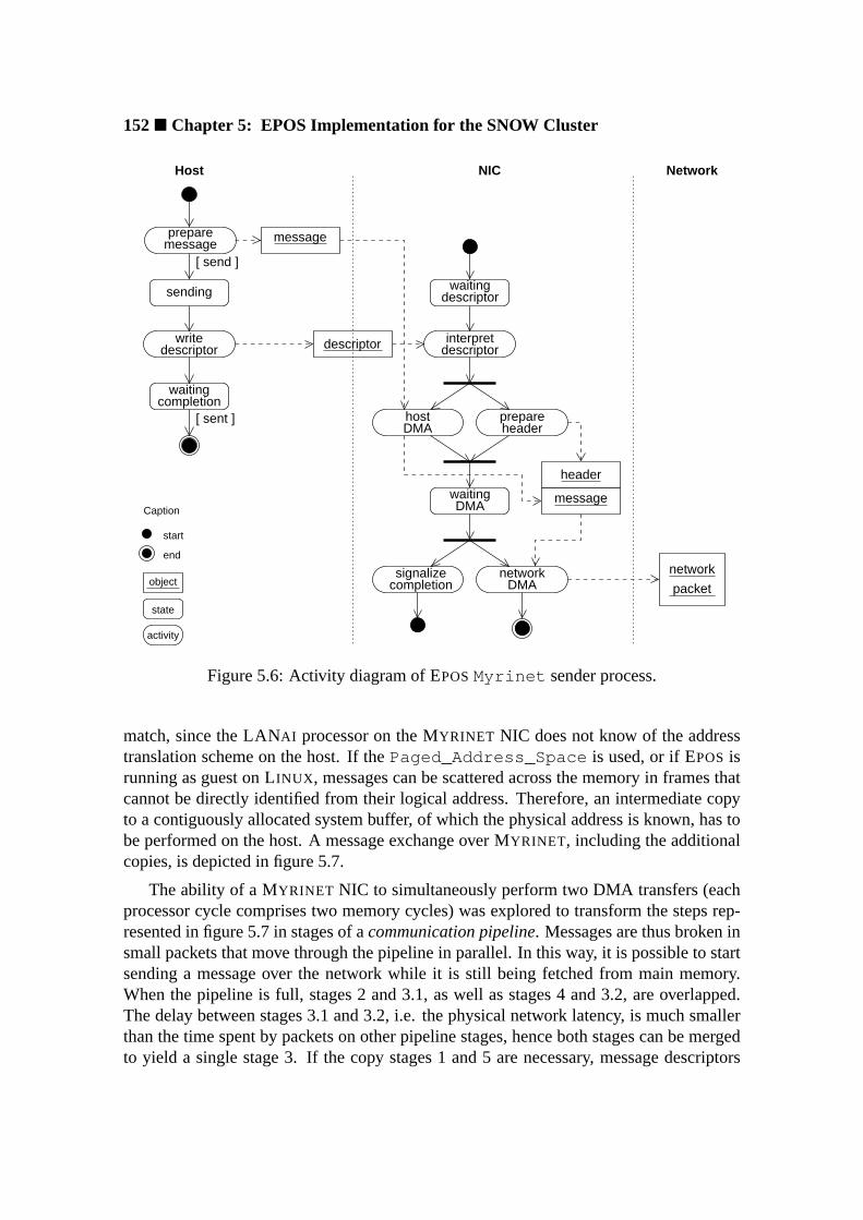
152� Chapter 5: EPOS Implementation for the SNOW Cluster
preparemessage
sending
writedescriptor
waitingcompletion
descriptorwaiting
hostDMA
prepareheader
signalizecompletion DMA
network
descriptorinterpret
state
activity
start
end
object
Caption
message
descriptor
header
messageDMA
waiting
network
packet
[ send ]
Host NetworkNIC
[ sent ]
Figure 5.6: Activity diagram of EPOSMyrinet sender process.
match, since the LANAI processor on the MYRINET NIC does not know of the addresstranslation scheme on the host. If thePaged_Address_Space is used, or if EPOS isrunning as guest on LINUX , messages can be scattered across the memory in frames thatcannot be directly identified from their logical address. Therefore, an intermediate copyto a contiguously allocated system buffer, of which the physical address is known, has tobe performed on the host. A message exchange over MYRINET, including the additionalcopies, is depicted in figure 5.7.
The ability of a MYRINET NIC to simultaneously perform two DMA transfers (eachprocessor cycle comprises two memory cycles) was explored to transform the steps rep-resented in figure 5.7 in stages of acommunication pipeline. Messages are thus broken insmall packets that move through the pipeline in parallel. In this way, it is possible to startsending a message over the network while it is still being fetched from main memory.When the pipeline is full, stages 2 and 3.1, as well as stages 4 and 3.2, are overlapped.The delay between stages 3.1 and 3.2, i.e. the physical network latency, is much smallerthan the time spent by packets on other pipeline stages, hence both stages can be mergedto yield a single stage 3. If the copy stages 1 and 5 are necessary, message descriptors

5.3 EPOS Implementation� 153
message
buffer
buffer buffer
buffer
messagememoryapplication
systemmemory
systemmemory
memoryapplication
Myrinet NIC Myrinet NIC
(1) copy (5) copy
(4) myrinet −> host DMA
(3.2) receive DMA
Myrinet network
Receiver
(3.1) send DMA
(2) host −> myrinet DMA
Sender
Figure 5.7: A message exchange with MYRINET.
are assigned on per-packet basis, so the processes on the MYRINET NIC are not forced towait for the copies to be completed. However, stages 1 and 2, as well as stages 5 and 4,concur for the same physical resource, namely memory, and will seldom overlap.
Furthermore, the proposed communication pipeline has a critical parameter: thepacket size. Adopting an excessively large packet size increases the pipeline’s setup time,while excessively small packets exacerbate the pipeline’s internal overhead. Furthermore,the influence of the packet size on the pipeline depends on the length of the messagesbeing transmitted. In order to estimate the optimal packet size as a function of the mes-sage length, the bandwidth of each pipeline stage and the latency experienced by packetson each stage were obtained. Applying a linear cost model, the optimal packet size fordifferent ranges of message lengths was calculated [Tie99]. The result was used to imple-ment an adaptive communication pipeline that automatically switches to the best packetsize for each message.
Although the communication pipeline has a low intrinsic overhead, programmingDMA controllers and synchronizing pipeline stages may be more onerous than usingprogrammed I/O for messages shorter than a certain length. Therefore, the pipeline isbypassed for messages shorter than a definable threshold (256 bytes by default in thecurrent implementation).
The performance of theMyrinet_Network abstraction implemented for the SNOW
cluster was assessed sending messages of increasing length from one node to another.Both the iX86-native (no copy) and the LINUX -guest (copy) versions were considered.Figures 5.8 and 5.9 show respectively the bandwidth and the latency observed during theexperiment. A bandwidth of 116 Mbytes/s for 64 Kbytes messages represents roughly90% of the bandwidth available to transfer data between main memory and the MYRINET
NIC over the 32 bits/33 MHz PCI bus that equips SNOW nodes.
Figure 5.8 makes evident the contention for memory access between pipeline stages
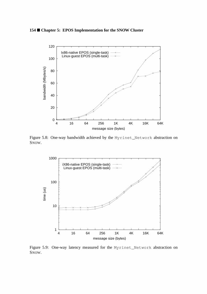
154� Chapter 5: EPOS Implementation for the SNOW Cluster
0
20
40
60
80
100
120
4 16 64 256 1K 4K 16K 64K
band
wid
th (
Mby
tes/
s)
message size (bytes)
Ix86-native EPOS (single-task)Linux-guest EPOS (multi-task)
Figure 5.8: One-way bandwidth achieved by theMyrinet_Network abstraction onSNOW.
1
10
100
1000
4 16 64 256 1K 4K 16K 64K
time
(us)
message size (bytes)
iX86-native EPOS (single-task)Linux-guest EPOS (multi-task)
Figure 5.9: One-way latency measured for theMyrinet_Network abstraction onSNOW.

5.3 EPOS Implementation� 155
1 (copy) and 2 (host to NIC DMA) in the LINUX -guest implementation. The iX86-nativeversion, which does not use stage 1, shows a growing advantage over the guest versionas the message length increases. Even if large messages are split in small packages, thebursts of memory transactions performed by both stages exceed the memory subsystemcapacity. This phenomenon is direct evidence that apparently harmless features of con-ventional operating systems that are enabled by design (multitasking support in this case)do indeed impact applications that do not need them.
5.3.2 Utilities
EPOSsetup utility[section 4.5.2.1] was implemented for SNOW taking advantage of theconfiguration capabilities of the service network. For ease of maintenance, SNOW com-puting nodes do not have disks. Hence, booting is accomplished by each node download-ing a boot image from the server over the service network. This boot image includes anode-specific description of EPOS—which among other configuration information con-tains the node’s logical id—and the executable image of the first process. In this manner,each node can be initialized with a distinct application (and consequently a distinct con-figuration of EPOS) or with distinct processes of a task-parallel application.
The initialization of data-parallel applications in aSingle Program, MultipleData (SPMD) configuration is accomplished with a single boot image that is downloadedfrom the server by all nodes. Subsequently, the setup utility replaces the in-image descrip-tion of EPOS with a node-specific version obtained from the server using theDynamicHost Configuration Protocol(DHCP) [Dro93] capabilities of the service network. There-fore, users can select the initialization strategy according to the needs of each application.
Both setup and init utilities expect executable images, including the operating sys-tem, to be in theExecutable and Linking Format(ELF) [Int95b]. This enables ordinarycompilation and linking tools on an iX86-based LINUX workstation to be used as a cross-compiling environment for EPOS. The separation of theinit utility [section 4.5.3.1] fromthe operating system image is accomplished using these tools. Theinit method of ev-ery abstraction is defined in a separate compilation unit that is linked with the init utility.Undefined references to EPOSaddresses are then resolved by the linker consulting (butnot linking) EPOSELF image.
5.3.3 Tools
A simplified version of EPOSsyntax analyzerwas implemented for SNOW. This analyzeris able to identify abstractions that are necessary to support the execution of applicationswritten in C++. It invokes the compiler indicated by the user to compile the applicationwith all inflated interfaces left unbound. If libraries are supplied, incremental linking isperformed in order to collect further references to EPOSabstractions contained in those
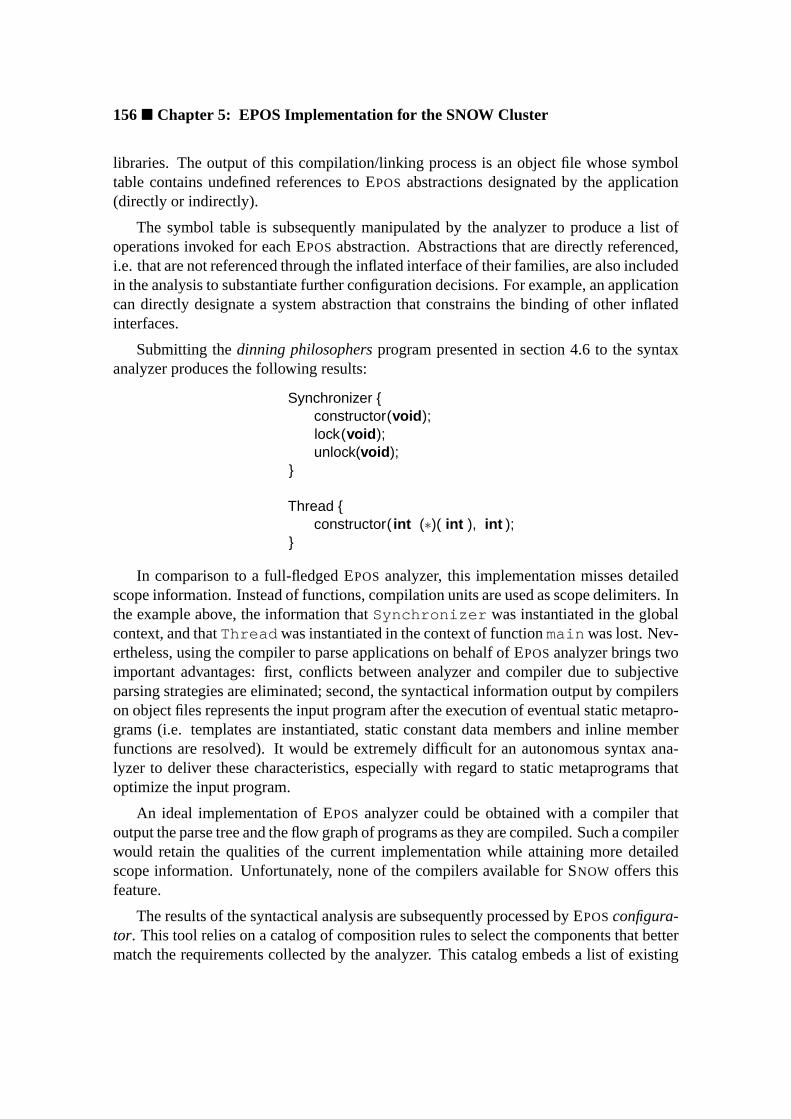
156� Chapter 5: EPOS Implementation for the SNOW Cluster
libraries. The output of this compilation/linking process is an object file whose symboltable contains undefined references to EPOS abstractions designated by the application(directly or indirectly).
The symbol table is subsequently manipulated by the analyzer to produce a list ofoperations invoked for each EPOSabstraction. Abstractions that are directly referenced,i.e. that are not referenced through the inflated interface of their families, are also includedin the analysis to substantiate further configuration decisions. For example, an applicationcan directly designate a system abstraction that constrains the binding of other inflatedinterfaces.
Submitting thedinning philosophersprogram presented in section 4.6 to the syntaxanalyzer produces the following results:
Synchronizer {constructor(void );lock(void );unlock(void );
}
Thread {constructor( int (∗)( int ), int );
}
In comparison to a full-fledged EPOS analyzer, this implementation misses detailedscope information. Instead of functions, compilation units are used as scope delimiters. Inthe example above, the information thatSynchronizer was instantiated in the globalcontext, and thatThread was instantiated in the context of functionmain was lost. Nev-ertheless, using the compiler to parse applications on behalf of EPOSanalyzer brings twoimportant advantages: first, conflicts between analyzer and compiler due to subjectiveparsing strategies are eliminated; second, the syntactical information output by compilerson object files represents the input program after the execution of eventual static metapro-grams (i.e. templates are instantiated, static constant data members and inline memberfunctions are resolved). It would be extremely difficult for an autonomous syntax ana-lyzer to deliver these characteristics, especially with regard to static metaprograms thatoptimize the input program.
An ideal implementation of EPOS analyzer could be obtained with a compiler thatoutput the parse tree and the flow graph of programs as they are compiled. Such a compilerwould retain the qualities of the current implementation while attaining more detailedscope information. Unfortunately, none of the compilers available for SNOW offers thisfeature.
The results of the syntactical analysis are subsequently processed by EPOSconfigura-tor. This tool relies on a catalog of composition rules to select the components that bettermatch the requirements collected by the analyzer. This catalog embeds a list of existing

5.3 EPOS Implementation� 157
<?xml version ="1.0"?><!DOCTYPE EPOSConfig SYSTEM "eposconfig.dtd"><EPOSConfig >...
<family id="Thread" type ="Incremental" default ="Exclusive"><member id="Exclusive" type ="Sole" pre="Task=Exclusive"/><member id="Concurrent" type ="Sole"/><member id="Cooperative" type ="Sole"/>
</family >...
<family id="CPU_Scheduler" type ="Uniform" default ="FCFS"pre="Thread=Concurrent">
...<family id="Synchronizer" type ="Dissociated" default ="Mutex">
<member id="Mutex"/><member id="Semaphore"/><member id="Condition"/>
</family >...</EPOSConfig >
Figure 5.10: Fragments of EPOScatalog of composition rules.
EPOS abstractions and a description of the target platform that serve as additional con-straints for the configuration procedure. In the current implementation, composition rulesare represented in theeXtensible Markup Language(XML) [W3C98]. An associatedDocument Type Definition(DTD) enables a flexible use of the rules catalog by diversetools.
Some fragments of the rule catalog concerning the dinning philosophers program an-alyzed earlier are depicted in figure 5.10. Families of abstractions are declared with thefamily element, while family members are declared with themember element in thescope of their families. Attributedefault of the family element designates the fam-ily member to be used in case the configurator does not have enough arguments to makea selection.
The order in which members are declared in a family designates their cost, the firstbeing the cheapest. Setting thetype attribute of amember element to “Sole” indicatesthat the member cannot be used simultaneously with other family members. In the caseof Thread , however, thetype attribute of family set to “Incremental” allows theconfigurator to replace a cheaper member with a more expensive one. For example, if acompilation unit is satisfied with the “Exclusive” member, but another requires “Cooper-ative”, the latter is used for the entire application.
Both family andmember elements can be assigned composition rules in the formdescribed in section 4.5.1.2. Attributespre andpos are used for this purpose. In fig-ure 5.10, member “Exclusive” of the “Thread” family depends on the member with the

158� Chapter 5: EPOS Implementation for the SNOW Cluster
Framework {constructor(Id const &);constructor(Framework const &);id (void );valid (void );
}...Mutex {
constructor(void );lock(void );unlock(void );
}
Semaphore {constructor( int );p(void );v(void );
}
Condition {constructor(void );lock(void );unlock(void );wait(void );signal(void );broadcast(void );
}...
Figure 5.11: Fragments of EPOScatalog of system interfaces.
same name from the “Task” family, and family “CPU_Scheduler” requires the “Concur-rent” member of the “Thread” family.
An interpreter for this configuration language was implemented in the context of agraphical front-end for EPOSconfiguration tools [Röm01]. Besides being able to guidethe process of tailoring EPOSto a particular application, this visual tool delivers a feature-based interface to manually configure EPOS. It shall be extended in the future to accom-plish amanagement consolefor SNOW, from which hardware and software maintenancetasks will be performed.
The interfaces of the abstractions listed in the catalog of composition rules are au-tomatically collected in a catalog of system interfaces applying the syntax analyzer toEPOScomponent repository. A stretch of EPOScatalog of system interfaces is depictedin figure 5.11. The special interfaceFramework comprises operations that are implicitlysupplied by the component framework to all abstractions. This entity is manually insertedin the catalog.
5.4 Summary� 159
In order to select the best realization for each inflated interface referenced by theapplication, the configurator crosses the output of the syntactical analysis with the catalogof interfaces. Realizations with interfaces thatcontainthe required signatures are probedconsidering the order specified in the catalog of composition rules. When one is foundthat matches the required signatures, the respective composition rules are checked. Ifno conflicts are detected, the inflated interface is bound to that realization, otherwise,the search continues. As explained in section 3.6, the impossibility to find an adequaterealization reveals either an application flaw, or a member of a dissociated family that hasnot yet been implemented.
Regarding the dinning philosophers program,Synchronizer would be bound tothe cheapest realization that features a default constructor and includes methodslockandunlock , that is,Mutex . In turn, theThread inflated interface would be boundto Concurrent , sinceExclusive does not provide the required constructor. As ex-plained in section 4.6, theCooperative member of theThread family has a loweroverhead thanConcurrent , but it is solely elected by methodpass , which is not real-ized byConcurrent (this was arranged reversing the order of both abstractions in thecatalog of composition rules).
A configuration produced by EPOS configurator consists ofselective realize keys,which designate the binding of inflated interfaces of abstractions and scenario aspects,andconfigurable feature keysthat designate the configurable features that must be enabledfor abstractions and scenario aspects. This set of keys is translated by EPOSgeneratortotypedefs andTraits structures that control the operation of the component frame-work metaprogram throughout the compilation of an EPOSinstance. Indeed, the generatorcannot be considered separately from the compiler, since actual generative tasks, such asthe adaptation of abstractions to scenarios and the composition of abstractions, are per-formed by the compiler as it executes the metaprogram.
5.4 Summary
Clustering commodity workstations as a cost-effective alternative to expensive massivelyparallel processors has been explored for quite a long time. Recently, improvementson commodity microprocessors and interconnects begun to make clusters competitivealso in absolute performance, suggesting that both hardware technologies are about tomerge. Regarding software, however, the dedicated run-time support systems used onMPPs show considerable advantages over the commodity workstation operating systemstypically used on clusters. In order to compensate the difference, commodity systems areoften patched with specialized subsystems, in particular user-level communication. How-ever, the inflexible structure of such operating systems severely restricts optimizations.
The prototype implementation of EPOS, which aims firstly at verifying design deci-sions, was strongly motivated by the possibility of introducing an application-oriented
160� Chapter 5: EPOS Implementation for the SNOW Cluster
operating system to the high-performance cluster computing scene, hence the decision ofimplementing it for the SNOW cluster of workstations. This cluster consists of 24 InteliX86-based processing nodes interconnected with a MYRINET high-speed network andconnected to a server through an FAST ETHERNET service network.
The implementation of EPOSfor SNOW was conducted as a last refinement of design,rather than an isolated phase. Constant feedback helped to enhance design specificationswhile yielding better support for implementation decisions. Abstractions, hardware medi-ators, scenario aspects, component framework, setup and init utilities, and configurationtools were implemented to produce two versions of the prototype: one that runs “natively”on SNOW, and the other that runs as a “guest operating system” on LINUX .
The implementation of theMyrinet_Network abstraction benefited from theLAN AI processor on the MYRINET interface card to shape an asymmetric multiprocessorconfiguration with the main processor, enabling the network to be modeled as a boundedbuffer. In order to communicate, application processes write message descriptors on thememory shared by both processors. Messages are then autonomously processed by theportion of Myrinet_Network abstraction that runs on the NIC, which profits fromthe parallel operation of MYRINET hardware components to implement a communicationpipeline.
The syntax analyzer implemented for SNOW is able to identify EPOSabstractions thatare needed to support the execution of applications written in C++. It uses the compilerindicated by the user to compile the application with all inflated interfaces left unbound,thus producing a symbol table with undefined references to EPOSabstractions. The sym-bol table is subsequently processed to produce a list of the operations invoked for eachabstraction.
The catalog of composition rules used by EPOS configurator was written in XML,with and associated DTD supporting a flexible use by diverse tools. By consulting thiscatalog, which embeds the relative cost of abstractions, the configurator is able to se-lect the components that better match the requirements collected by the analyzer. Theoutput of this configuration process are selective realize and configurable feature keys,which are subsequently translated intypedefs andTraits structures by the gener-ator. The fact that EPOSgenerator does not manipulate the source code of abstractionsand scenario aspects directly—the component framework metaprogram does it in behalfof the generator—allowed this simple implementation. However, working together, gen-erator and framework are able to adapt and compose selected abstractions to produceapplication-oriented instances.
Chapter 6
Discussion
This chapter discusses application-oriented system design, identifying its highlights andlimitations. Comparisons with related design strategies will be made, and the possibilitiesof deploying it to support the design of other kinds of software than application-orientedoperating systems will be considered. A similar study is subsequently presented for theEPOSsystem. The chapter is closed with a discussion about the perspectives of furtherdevelopment and deployment of the ideas proposed in this dissertation.
6.1 Application-Oriented System Design in the Realm ofSoftware Engineering
Application-oriented system design is a software development methodology that ad-dresses issues concerning the engineering of statically configurable system-level software,in particular application-oriented operating systems. The method approaches static con-figurability by guiding the decomposition of the envisioned domain into software com-ponents that can be assembled to produce system instances according to the needs ofparticular applications, thus filling the gap left by all-purpose operating systems.
As a methodology specially conceived to support the development of system-levelsoftware, application-oriented system design presents many advantages when comparedto less specific methodologies. One important factor ignored by other methodologies isthat operating system abstractions often enclose entities that span three different domains:hardware, operating system, and application. If these domains are not properly bridged,a situation may arise in which system components exhibit excellence at one level, butdisappoint at another. By considering application-specific views of domain entities andseparating scenario aspects from abstractions, application-oriented system design consis-tently addresses this issue.
Regarding operating system design peculiarities, many conventional design method-
162� Chapter 6: Discussion
ologies presuppose a single paradigm. At the begging of the “object revolution”, itwas often claimed that object-oriented methods that could prevent “design slips to-ward other paradigms” were able to produce better designs. Nowadays, the combina-tion of paradigms is commonly practiced by software designers, which profit from eachparadigm’s strengths to deal with distinct design issues. System-level software makes thelimitations of a single paradigm more evident, since modeling some physical devices, inparticular with regard to synchronization and timing, challenges any individual paradigm.Aware of this, application-oriented system design combines techniques from differentparadigms (e.g. aspect separation and variability analysis), as well as making room forspontaneous combinations.
Several design methods are being used to guide the development of component-basedsoftware, but not many of them have been conceived explicitly for this purpose. Themost common deficiency of such methods is the absence of a domain analysis and de-composition strategy. Consequently, many software components are being defined in thescope of specific systems (instead of a domain) and do not achieve the expected degreeof reusability. Application-oriented system design features a well-defined process to de-compose a domain into abstractions that capture application-specific perspectives of eachdomain entity. Instead of modeling monolithic abstractions, commonality and variabilityanalysis build families of abstractions. Abstractions strongly connected by commonalitiesare gathered in the same family, while variability analysis renders the particular charac-teristics of each family member.
Another common deficiency of those design methods is the inability to guide theseparation of scenario aspects from abstractions. Scenario-specific abstractions usuallycan only be deployed within the scenario for which they have been conceived, limitingreusability. Application-oriented system design emphasizes the separations of executionscenario aspects from abstractions, extending variability analysis to determine whether avariation is inherent to the family or whether it originates from one of the execution sce-narios considered. Scenario-independent abstractions—which can be reused in a varietyof scenarios—are the outcome of this procedure.
Another important advantage of application-oriented system design is that it fostersthe definition of software components during domain decomposition, while most othermethods cover the issue later during the specification of a physical model. Complica-tions to match abstractions and components often arise with those methods, especiallywith regard to cross-component properties and excessively large components. Therefore,each application-ready abstraction in an application-oriented system design is modeledto yield exactly one software component that can be independently deployed. System-wide properties that crosscut component boundaries are modeled separately as scenarioaspects.
The separation of concerns promoted by application-oriented system design helps toproduce less complex software artifacts, improving most software quality metrics. How-ever, the subdivision of abstractions into families could affect maintainability, since the

6.1 AOSD in the Realm of Software Engineering� 163
number of software artifacts produced can be quite high. Nevertheless, modeling scenarioaspects, each of which applies to several abstractions, and configurable features that re-place the specialization of all individual members of a family by a single construct, shouldkeep the number of elements in an application-oriented system design at manageable lev-els.
A large number of components could also impair usability, for application program-mers might not be able to select and compose so many items. Therefore, application-oriented system design assigns every family an inflated interface, which allows wholefamilies to be used as single abstractions. Furthermore, application-oriented system de-sign exploits inter-family relationships to model reusable software architectures in theform of component frameworks. These frameworks prevent users from carrying out erro-neous compositions.
The scenario adapter concept is another strength of application-oriented system de-sign. It provides a controllable mechanism to apply scenario aspects to abstractions,sustaining the separation of concerns pursued during domain decomposition. Scenarioadapters act as agents that mediate the interaction between scenario-dependent clientsand scenario-independent abstractions. These constructs can be implemented with staticmetaprogramming techniques to yield a low-overhead adaptation and composition mech-anism that can be used to build component frameworks.
An application-oriented operating system designed according to the guidelines ofapplication-oriented system design can be tailored to particular applications through theselection of abstractions, scenario aspects, and configurable features that are arranged in acomponent framework. In addition, the inflated interface binding mechanism used to se-lect system parts can be controlled externally, allowing for the automation of the tailoringprocess. Tools can analyze applications and available system components to determinethe most adequate system configurations.
Notwithstanding the robustness of its concepts, application-oriented system designcertainly has limitations. Noticeably, application-oriented system design requires users tobe familiarized with object-oriented design, from which it inherits a series of concepts,but then defies some of its basic notions with scenario aspects and inflated interfaces.This might bring confusion to the mind of some designers. Concepts such as families ofabstractions and component frameworks are more intuitive and should be easily accepted.
Nevertheless, conflicts between object-oriented design and application-oriented sys-tem design are insignificant when compared to what may be caused by inviting an operat-ing system designer to consider application-orientation. Typical operating system designsare strongly constrained between hardware and standardized application program inter-faces, rendering many software engineering techniques inapplicable. The removal of thesuperior “lid” by application-oriented system design may leave some designers aimless.In this situation, the higher complexity of application-oriented system design conceptsmay be unmanageable.
164� Chapter 6: Discussion
Indeed, the complexity of an application-oriented system design may exceed that ofdesigns produced with other methodologies, for high scalability is achieved with a con-siderable increase in the number of software artifacts. These artifacts are individuallysimpler than those otherwise produced, being easier to specify, implement, and maintain.However, the complexity of the system as a whole will certainly exceed that of a mono-lithic design. Nevertheless, the adoption of UML as design notation enables application-oriented system design to be conducted with the aid of a variety of CASE tools that featurepowerful mechanisms to manage complex sets of software artifacts.
6.1.1 Comparison with other Methodologies
Application-oriented system design will be subsequently compared with the design meth-ods discussed in chapter 2. Although some of those methods do not envision domainengineering, and do not explicitly address issues concerning operating system design,they feature techniques that can be used to build application-oriented operating systems.This comparative study aims at identifying similarities, advantages, and disadvantages ofapplication-oriented system design with regard to those methods.
Family-based design: Application-oriented system design shares several common as-pects withfamily-based design[section 2.2.1]. Both methodologies emphasizesepara-tion of concerns, deploying commonality and variability analysis as the basic domaindecomposition strategy. Domain entities whose commonalities are more significant thanvariations are grouped infamilies.
However, family-based design and application-oriented system design disagree onsome important points. Family-based design does not put limits on what family mem-bers can be. A family-based design could come up with families of elementary functionsalongside families of complex abstractions. This seeming flexibility makes it difficult tomatch logical and physical design models in the context of a component-based system, forsome logical entities yield an excessive number of components, while others cross com-ponent boundaries. Application-oriented system design copes with this issue guiding thespecification of application-ready abstractions that directly correspond to components.
Furthermore, family-based design does not emphasize the separation ofscenario as-pects, interpreting them as ordinary variability that yields new family members. Thisseverely affects the reuse of a family in new scenarios, besides complicating maintenancewith a substantial increase in the number of family members.
Application-orientation is addressed in the context of family-based design byincre-mental system design[section 2.2.1.1], which fosters the modeling of families with aminimal basisto which successiveminimal extensionsare applied all through the appli-cation. In comparison to application-oriented system design, this strategy has a majorshortcoming: theminimalcriterion for extensions, in addition to the lack of scenario as-

6.1 AOSD in the Realm of Software Engineering� 165
pect separation, can result in a family containing an exaggerated number of elements.Consequently, management and use become complicated, and matching the application’sneeds impractical. For instance, thethread family tree could comprise dozens of levelsfrom its patriarch co-routine to a remotely accessible, multiprocessor- and multitask-readydescendant.
Compared to thefamily-oriented abstraction, specification, and translationvariantof family-based design, application-oriented system design is in disadvantage in whatregards the representation of commonalities. That method utilizesapplication-orientedlanguagesto quickly specify commonalities, which are subsequently regarded as de-sign secrets. In this way, domain decomposition can concentrate on variability analysis.Application-oriented system design does not contemplate such languages, so the model-ing of commonalities demands more effort. Nevertheless, specifying such languages inadvance to domain decomposition can be a defying task.
Object-oriented design: Application-oriented system design is a multiparadigm de-sign method centered on object-orientation. Therefore, manyobject-oriented design[sec-tion 2.2.2] techniques are reused in an application-oriented system design. Besides com-mon aspects inherited from family-based design, both methodologies abstract domainentities asobjects. Commonalities lead objects to be gathered inclasses, while variabilitybuilds class hierarchies.
Nevertheless, class hierarchies constitute just one of the strategies to build a fam-ily in the realm of application-oriented system design. Representing adissociated fam-ily—whose members are usually strongly connected by semantics, but lack a commonstructure—as a class hierarchy leads advanced family members to incorporate unneces-sary elements, consequently compromising application-orientation. Moreover, the fragilebase class of such an hierarchy often fails to carry on family extensions, having to bereformulated to accommodate members not initially considered, sometimes even affect-ing other family members. In contrast, the factorization of a dissociated family as guidedby application-oriented system design causes commonalities to be gathered in acommonpackage(instead of a base class). Elements of a common package are individually reusedby each family member.
Both methodologies recognize the importance of giving different members of a fam-ily a common interface, so it can be handled as a single abstraction. However, object-oriented design’s answer to the question,polymorphism, has considerable shortcomingswhen compared to application-oriented system design’sinflated interfaces. First of all, theinflated interface concept does not exclude polymorphism. An inflated interface allowsthe designer to decide whether the common interface assigned to a family of abstrac-tions implies in subtyping relationships between their members or not. This is especiallyimportant to preserve domain correspondence in dissociated families, whose membersdefine independent types. Polymorphism would require such families to be modeled asa class hierarchy with an artificial base class that is not sustained by the organization of

166� Chapter 6: Discussion
corresponding entities in the domain.
Considering implementation, representing the common interface of a family as aninflated interface, instead of a polymorphic abstraction, has two main advantages:
• Inflated interfaces result in less run-time overhead and better memory utilization,for no indirect procedure call mechanisms are necessary and only effectively usedfamily members are included in a system configuration (the exact type of a polymor-phic object is only defined at run-time, so all connected types have to be included).
• Inflated interfaces can be externally bound at compile-time without modificationsto the source code, while polymorphism shifts issues concerning family memberselection to run-time. Selecting a family member at run-time, however, may requirecomplex pieces of configuration tools be embedded in the application.
Another significant difference between application-oriented system design and object-oriented design concerns scenario aspects. While application-oriented system design iso-lates them from abstractions, object-oriented design models scenario-specific specializa-tions of abstractions. Such specializations can seldom be reused in a different scenario.Moreover, if the implementation of a scenario aspect needs to be modified, the corre-sponding specializations of all families of abstractions designed to perform in that sce-nario have to modified. A single element would be modified in an application-orientedsystem design.
Replacing the modules of an object-oriented design’s physical model with compo-nents can usually be straightforwardly accomplished. However, object-oriented designdoes not directly address inter-family relationships that cross the boundaries of modules,so achieving components that can be individually reused may require a large effort fromdesigners. Likewise, object-oriented design does not feature techniques to specify howcomponents can be composed to yield a concrete system. Application-oriented systemdesign addressed both issues withcomponent frameworks, which model reusable systemarchitectures that emanate from inter-family relationships.
Collaboration-based design: One important concept ofcollaboration-based de-sign[section 2.2.3] incorporated by application-oriented system design is that abstractionscan play different roles in different contexts. However, this concept is deployed quite dif-ferently in both methodologies. In collaboration-based design, objects are explicitly mod-eled considering the roles they can play in predicted collaborations. Application-orientedsystem design explores the concept to model variations in the behavior of abstractionsthat originate from different execution scenarios. Therefore, scenario aspects can be un-derstood as externally defined roles of abstractions. When a scenario aspect is applied toan abstraction with a scenario adapter, the abstraction “starts to play the correspondingrole”, thus collaborating in a scenario.
6.1 AOSD in the Realm of Software Engineering� 167
When a software development methodology is deployed to engineer a domain, insteadof a single system, reusability assumes a broader connotation. Predicting which fractionsof a domain will be covered by each system is usually not possible, therefore domainentities must be modeled to be reused in disregard of each other, yielding independentlydeployable components. Collaboration-based design was one of the first methodologies toacknowledge this necessity, guiding the specification of independently deployable collab-orations. Application-oriented system design extends this notion to model independentlydeployable abstractions.
The design of EPOSdescribed in chapter 4 covers abstractions and scenario aspects inthe domain of high-performance dedicated computing. The engineering of such a com-plex domain revealed that specifying independently deployable abstractions, more than asource of improvements, is a necessity. Modeling abstractions to be reused independentlyof each other, independently of scenario aspects, and independently of predefined systemarchitectures, drastically simplifies their design, improving overall quality.
When EPOSbegun to be designed, it was not clear that such a level of independencecould be achieved, so more traditional designs were first considered. For instance, anobject-oriented framework, in which abstractions extend framework entities. Such a de-sign would have created unnecessary dependencies that would complicate reusability.Another possibility considered was to deploy external tools, much in the sense of aspect-oriented programming, to modify EPOScomponents in order to enable them to be reusedin specific scenarios. Such tools became superfluous for EPOS, partially because of thestatic metaprogramming techniques adopted, but mainly because of the degree of inde-pendence promoted by application-oriented system design, which allowed abstractions tobe adapted without external manipulation.
Subject-oriented programming: Comparing subject-oriented programming[sec-tion 2.2.4] with application-oriented system design would make little sense, for bothmethods cover very different segments of the software engineering spectrum. Whileapplication-oriented system design targets the engineering of the operating system domainas a collection of reusable abstractions that can be configured to match the requirementsof specific applications, subject-oriented programming extends object-oriented program-ming to handle issues concerning the extension of existing software without modifyingthe original source, and the decentralized development of classes.
Nevertheless, the subject-oriented programming observation that different clients maybe interested on different aspects of a class, leading tosubjective viewsof it, meetsapplication-oriented system design domain decomposition strategy, withsubjectsbeingrepresented either as members of a family of abstractions or as scenario aspects, and sce-nario adaptersreconciling subjective viewsmuch like subject composition does in subject-oriented programming.
It would be more appropriate to compare subject-oriented programming tools to thoseintroduced by EPOSto support automatic configuration [section 4.6]. Clearly, the subject-

168� Chapter 6: Discussion
oriented programming project at IBM Research [IBM01] is a much larger project than thisdissertation, with tools that are far more elaborate. Nonetheless, both set of tools rely onexternally defined composition rules and deploy statically metaprogramming techniques.Subject-oriented programming C++ support is able to derive abstract description of com-ponents (subject labels) from their source code. A similar description is obtained forEPOS applying the syntactical analyzer to the component repository. Labels are subse-quently composed, in accordance with composition rules written in a specific declarativelanguage, to produce a result label that describes the composed subject. EPOSrelies on acatalog of rules written in XML for the same purpose. Both processes end with a genera-tor processing a composite description.
Nonetheless, subject-oriented programming tools were conceived to operate witharbitrarily designed systems, while EPOS tools are intrinsically dependent from anapplication-oriented system design. This allows EPOS tools to analyze target applica-tions in order to select the components that better serve them, an unknown notion tosubject-oriented programming tools.
Aspect-oriented programming: Similar to subject-oriented programming,aspect-oriented programming[section 2.2.5] does not really feature a design methodology. Theidea of isolating non-functional aspects in reusable constructs is not sustained by a sys-tematic domain decomposition strategy. Moreover, functional aspects are given secondaryimportance by aspect-oriented programming techniques. Nevertheless, aspect-orientedprogramming emphasis on aspect separation is upheld by application-oriented system de-sign.
Furthermore, aspect-oriented programming techniques and tools can be useful to im-plement application-oriented system designs. In this case,aspectswould implementsce-nario aspects, andweaverswould play the role ofscenario adapters. This would bringone major advantage over the original scheme: describing aspects with specialaspect lan-guagescould considerably reduce efforts and improve correctness. However, the effort toimplement such tools and to specify an aspect language would only be worthwhile in thelong term. Besides, the correctness enhancements obtained by specifying aspects with amore adequate language can vanish in the face of the nuisance of congregating differentlanguages, processed by different tools, at generation-time.
6.1.2 Support for other Kinds of Design
Application-oriented system design has been conceived aiming at engineeringapplication-oriented operating system as a collection of statically configurable softwarecomponents. However, many of the concepts introduced by application-oriented systemdesign can be useful to design other kinds of software as well.

6.1 AOSD in the Realm of Software Engineering� 169
Dynamic configurable operating systems: Application-oriented system design doesnot exclude dynamic configurability. Some statically composed abstractions includedynamically reconfigurable elements, as with EPOS CPU_Scheduler abstraction de-scribed in section 4.3.2.3. Deploying application-oriented system design to model a full-dynamically reconfigurable system would also be possible, but some important issuesregarding this kind of system are not covered by the method.
Apparently, deploying application-oriented system design as-is, and following a par-ticular implementation discipline could achieve the desired effect. Inflated interfaceswould be implemented as abstract base classes, and abstractions would be implementedas subtypes of their family’s interface. A framework element, similar tohandle in thecontext of EPOS (see section 4.5.1), would build anabstract factory[GHJV95] for ab-stractions, allowing different members of a family to be dynamically created. In thiscontext, all abstractions would be included in the system at compilation-time to be freelydeployed at run-time. If incremental loading is desirable, a strategy similar to the oneexplained in [DSS90] could be easily devised thanks to the degree of independence ofabstractions.
However, supporting dynamic reconfiguration in the style ofreflective systemswouldbe a major challenge, since application-oriented system design does not address someimportant issues concerning the subject. In order to support the systematic constructionof reflective operating systems, a design method would have to guide the modeling ofabstractions considering theirmeta-levelrepresentation and the meta-level interactionsthat drive dynamic reconfiguration.
All-purpose operating systems: Deploying application-oriented system design tomodel an all-purpose operating systems should be straightforward. Application-orientedsystem design could be applied to engineer an all-purpose operating system as if it wasan application-oriented operating system, differentiating only during the generation of asystem instance. In other words, any application-oriented operating system can be config-ured to perform as an all-purpose operating system. Such instances would be generatedincluding all members of uniform and dissociated families plus the most comprehensivemembers of incremental families and full merged members of combined families. Like-wise, all scenario aspects and configurable features would be activated. In this way, allthe functionality modeled for the system would be available to generic applications.
Although such a system would not be distinguishable from a generic operating systemfrom the application point of view, engineering it according to application-oriented systemdesign directives would bring system developers all the advantages of component-basedsoftware, especially reusability and maintainability.
Applicative software: Application-oriented system design could also be used to modelapplicative software, conferring it the same scalability of an application-oriented operat-

170� Chapter 6: Discussion
ing system and all the benefits of a component-based realization. However, some conceptsof application-oriented system design originate from the necessity of bridging hardwareentities with application abstractions. This does not hold for applicative software. Itis likely that an application design would comprise less dissociated families and moreuniform ones, for many dissociated families arise from hardware idiosyncrasies. Further-more, a slightly different criterion to identify scenario aspects and configurable featureswould be necessary in this case, since environmental and built-in properties might bedifficult to distinguish in a smoother scenario (i.e. a scenario that does not span distinctdomains). This has also been acknowledged by aspect-oriented programming [MLTK97].
6.2 EPOS in the Realm of Operating Systems
EPOS (Embedded Parallel Operating System), the experimental application-orientedoperating system developed in the scope of this dissertation, is the outcome of anapplication-oriented decomposition of the high-performance dedicated computing do-main. It consists of a collection of abstractions and scenario aspects that can be arrangedin a component framework to produce system instances according to the necessities ofparticular applications.
Notwithstanding the intricacy of the target domain, the separation of concerns pro-moted by application-oriented system design greatly simplified the specification of EPOS
individual elements, much in a “divide and conquer” strategy. The implementation of aprototype for the SNOW cluster made it clear that the increase in complexity resultingfrom successive partitioning is well worth paying. Compared to ABOELHA1, EPOS isfar more flexible and maintainable. ABOELHA’s µ-kernel has been designed to be quitecompact, suggesting that further decomposition was not necessary. However, its mono-lithic, scenario-dependent abstractions are extremely difficult to maintain. Often, minormodifications in one abstraction trigger undesirable side-effects on other “apparently in-dependent” abstractions, causing the whole system to undergo a new extensive test phase.
Having followed the directives of application-oriented system design to decomposethe domain of high-performance dedicated computing, EPOS was able to specify au-tonomous families of abstractions. These abstractions concentrate on essentials of thedomain entities they abstract, while environment-related properties were separately cap-tured as scenario aspects. In addition, a factorization process collected family commonal-ities in common packages and configurable features. This thorough partitioning producedsoftware components that can be independently deployed and maintained, hence mini-mizing adverse side-effects.
Capturing elements of reusable software architectures in a component framework alsocontributed to make EPOShighly scalable. Unlike traditional object-oriented frameworks,
1ABOELHA is a former operating system developed by the author [FAPS96]. It was designed around aµ-kernel that constitutes a run-time support substrate for distributed objects.
6.2 EPOS in the Realm of Operating Systems� 171
the EPOScomponent framework does not require abstractions to conform to specific im-plementation directives, or to incorporate special constructs. This design allowed theframework static metaprogram to be successively streamlined without affecting abstrac-tions and scenario aspects. The resultant component framework is more intelligible, hasa null intrinsic overhead, and sustains a scalable software architecture that enables EPOS
to support applications of assorted complexity.
Another fundamental design decision was the isolation of non-portable elementswithin the sphere of hardware mediators and the setup utility. This isolation allowedabstractions that interact with hardware, such asThread andAddress_Space , to bemodeled in multiple levels, each one dealing with specific issues. Even though EPOS
has not yet been ported to other hardware platforms, the guest-level implementation forL INUX corroborated many design aspects concerning portability, since most hardwaremediators were redefined for that implementation with no impact on abstractions and sce-nario aspects.
As a domain engineering venture, EPOS aspires reaching out to “all” entities in thetarget domain. This aspiration, however, is definitely unachievable, since an applicationdomain is not an exact concept that can be absolutely characterized, but a subjective setof entities, concepts, techniques, etc. Although EPOS features an ample perspective ofthe high-performance dedicated computing domain, certainly many particularities havenot yet been covered. For instance, the extensive set of abstractions, hardware mediators,and scenario aspects that makes up the process abstraction in EPOS, when subjected tothe criticism of other system designers, revealed deficiencies in regard to some particularapplication use-cases.
As currently modeled, EPOS is unable to deliver the benefits of theExclu-sive_Thread abstraction [section 4.3.2.2] to applications executed by a single threadper processor on a multiprocessor node (it presupposes a single thread per node). How-ever, suppressing memory management and scheduling would be possible in such casesand would considerably enhance performance. Fortunately, the application-oriented sys-tem design of EPOSallows for extensions. TheThread family could be enriched with aProcessor_Exclusive member that would extendExclusive to provide for themissing support. TheTask family could be similarly extended to allow multiple single-threaded tasks to benefit from the proposed optimizations2.
EPOSfeatures a set of configuration tools that are able to automatically tailor the sys-tem to specific applications, identifying and configuring necessary abstractions and sce-nario aspects and subsequently generating a customized system instance. This automaticconfiguration strategy is of great value for users, who are freed from much of the bur-den of system configuration. Nevertheless, it is restricted to application requirements thatcan be expressed through syntax, falling back to manual configuration otherwise. Com-
2In platforms that do not provide address relocation mechanisms, the abstractionProces-sor_Exclusive_Task would be assisted by the configuration tools to issue appropriate base addressesfor tasks, thus shaping aMutual_Flat member for theAddress_Space family.
172� Chapter 6: Discussion
pared to systems that only support manual configuration, this is an advance, but EPOS
configuration tools could be extended to support more sophisticated approaches.
Complementing the syntactical analysis of applications with data-flow analysis, forexample, could render more accurate application requirements. Some system opera-tions explicitly invoked by the application, especially regarding synchronization, couldbe proven unnecessary by such analysis. They could be automatically suppressed.
Another aspect of the existing configuration tool set that could be improved is thetie-break criterion: when application requirements are fulfilled by two or more mem-bers of a family of abstractions, the one with the lowest overhead is taken. This costmodel disregards significant properties of abstractions that could lead to better configura-tions. The uniform family of scheduling policies maintained byCPU_Scheduler [sec-tion 4.3.2.3] is particularly affected by the adopted model, because, being a uniform fam-ily, its members are syntactically equivalent. Some applications give syntactical hintsabout the scheduling policy that should be used (e.g. explicitly assigning priorities tothreads, changing the time-slice length, designating a user-defined thread to perform therole of scheduler), but many do not. In such cases, the overhead criterion electsFCFSasthe scheduling policy, since it has the lowest run-time overhead. Obviously, this arbitrarydecision is often inadequate. Evaluating the configuration as a whole to collect “hints”about tied abstractions would increase the ratio of optimal configurations. For instance,evidences of concurrency, such as task creation and memory sharing, could increase thecost ofFCFS, eventually electing another policy.
6.2.1 Comparison with other Systems
Few operating systems describe the more abstract levels of their designs, usually con-centrating on details about outstanding services. In this context, identifying systems thatemphasize application-orientation becomes difficult. Nonetheless, some operating sys-tems have been identified that render an interesting comparative study with EPOS.
CHOICES The CHOICES object-oriented operating system [CJR87, CIM92] at theUniversity of Illinois at Urbana-Champaign has been designed as a hierarchy of object-oriented frameworks and implemented in C++. Each of CHOICES frameworks corre-sponds to a subsystem (e.g. virtual memory, file system, etc) that can be customizedthrough the use of inheritance. System resources, policies, and mechanisms are repre-sented as objects in the context of the corresponding framework.
CHOICESembodies the notion of customizing the operating system to support partic-ular hardware configurations and applications. However, compared to EPOS, CHOICES
components are large and not very customizable. Indeed, CHOICES would be better un-derstood from the perspective of all-purpose operating systems, since its complex subsys-tems are not specialized with regard to applications needs. Moreover, CHOICES mono-

6.2 EPOS in the Realm of Operating Systems� 173
lithic abstractions are difficult to reuse separately, because they incorporate frameworkelements and scenario aspects.
ETHOS The ETHOS reflective operating system [Szy92] at the Swiss Federal Instituteof Technology covers extensible objected-oriented programming from the hardware up tothe applications. It has been modeled as a strongly typed hierarchy of abstractions, forwhich default implementations exist.
While ETHOS explores dynamic configurability, EPOS is essentially a statically con-figurable system. Nevertheless, both systems agree about the limitations of inheritance toimplement a customizable design. ETHOS pursues extensibility restricting the use of in-heritance in favor of forwarding, withdirectory objectsacting as proxies to extensions. Inthis way, extensions (modules) can be dynamically loaded. EPOSuses a similar forward-ing strategy with its statically metaprogrammed scenario adapters, so that abstractionsincorporate scenario aspects without having to inherit them. Furthermore, application-oriented system design supplies EPOSwith a range of alternatives to traditional class hi-erarchies, including dissociated families, scenario aspects, and static metaprogramming.Combined, they prevent unnecessary dependencies and foster independent deployability.
PEACE The PEACE parallel operating system [SP94a] at GMD-FIRST follows theguidelines of family-based design. PEACE embodies the notion of application-orientationas it embraces a particular domain, namely parallel computing, with a set of predefinedconfigurations aimed at particular application classes. The high-performance demandedby parallel applications was supplied by PEACE with a thrifty implementation concernedin making resources available to applications with as little overhead as possible. Severalof these concepts have been reused in EPOS.
Nevertheless, PEACE design is essentially incremental, exporting a large number ofelements that result from the successive extension of primordial ones. Selecting the properelements to assemble an application-oriented operating system is a major difficulty inthis context. Indeed, PEACE’s ability to match up application requirements hinges on anintricate set of conditional compilation flags, in practice being restricted to a small setof predefined configurations. Application-oriented system design allows EPOS to reacha similar degree of configurability at the application side while keeping the number ofexported elements (abstractions and scenario aspects) at manageable levels. Furthermore,inflated interfaces and scenario adapters mostly dispense with conditional compilationflags.
FLUX The FLUX [FBB+97] operating system toolkit at the University of Utah consistsof a blackboxframework and a set of components (object files) organized in libraries. Inorder to configure an operating system, users choose between libraries and object files,which are subsequently linked to produce a system instance. Therefore, FLUX emphasizes

174� Chapter 6: Discussion
the reuse of unmodified binary components.
The notions of non-invasive framework and independent reuse explored by FLUX
are upheld by EPOS. However, the preference for binary components diverges fromapplication-oriented system design, since it prevents many customizations and hinders im-portant concepts such as scenario aspect separation and functional factorization. Further-more, FLUX components are relatively coarse, comprising device drivers and completesubsystems (e.g. file system), and can hardly be reused outside the scope of all-purposecomputing.
PURE The PURE [SSPSS98] system at the University of Magdeburg defines a largeset of fine-grained components that can be arranged to build system abstractions in therealm of embedded computing. Consequently, it shares many goals with EPOSas regardsapplication-orientation and dedicated computing. However, PURE pursues such goals inessentially different ways.
PURE is mostly a family-based design, whose incremental families of abstractions arerealized as class hierarchies. This strategy was inherited from PEACE [SP94a] and bringsabout the configurability and usability pitfalls discussed earlier: PURE exposes its inter-nal structure to applications, delivering intermediate abstractions that are not application-ready. PURE recognizes that managing such a large set of components is beyond mostusers’ grasp and is currently working on user-driven, feature-based tools to automate theprocess [BSPSS00]. EPOS, on the other hand, bets on application-driven configuration,delivering a set of tools that is able to configure application-specific instances automat-ically. However, this improvement in usability and maintainability is achieved at theexpense of granularity3: EPOSdoes not match PURE’s degree of configurability.
6.3 Perspectives
The application-oriented system design method proposed in this dissertation is able toguide the construction of highly customizable run-time support systems as an arrange-ment of adaptable software components. Such application-oriented operating systemscan be tailored to specific applications through the selection of appropriate system ab-stractions that are adapted to match the environment in which applications perform, andsubsequently “plugged” into a component framework.
The adequacy of application-oriented system design to conduct the design ofapplication-oriented operating systems was corroborated by EPOS with the engineeringof the high-performance dedicated computing domain. Application-oriented system de-sign made it possible to decompose that domain into an extensive set of application-readyabstractions, which can be reused to build a variety of run-time support systems. Indeed,
3A reasoning about component granularity is presented in section 2.3.2.
6.3 Perspectives� 175
EPOSattested that managing a complex set of small software artifacts that preserves do-main correspondence is more productive than managing a small set of complex monolithicartifacts.
However, both application-oriented system design and EPOSare open projects withinteresting possibilities for further research. In the realm ofsoftware engineering, CASEtools could be explored to increase the efficiency of application-oriented system design.Many elements of an application-oriented system design result from the detailing of thesame domain entity, leading to mechanical replication that could be carried out automati-cally by such tools. For instance, the operations declared for each EPOSabstraction appearon a number of constructs, including the abstraction’s interface, its family’s inflated inter-face, scenario adapter, proxy, and agent. Ideally, these constructs should be automaticallygenerated from an abstract description4, which would also serve configuration purposes.
If such abstract descriptions of an application-oriented operating system componentsare boosted towardsformal methods, verifying the correctness of component assemblagescould be supported. The partitioning promoted by application-oriented system designyields individually simpler components that are more suitable to formal specification thanconventional operating systems “components”. Furthermore, formal methods could guideautomatic configuration tools towards the optimal system configuration for an application.
In the realm ofoperating systems, an extensive implementation of EPOSwould deliverdedicated applications services of unprecedented quality, whereas they originate from anapplication-oriented perspective of the dedicated computing domain. Moreover, EPOS
scalable design allows for the quick incorporation of novel ideas, thus providing an idealplatform to experiment with operating systems.
Outside the scientific ring, however, the possibilities for application-oriented operat-ing systems are not as promising. Besides the resistance of users to new ideas in theoperating system field, many existing applications have little chance to profit from the ad-vances of an application-oriented operating system. This became evident with the attemptto bring existing parallel applications to execute on the SNOW cluster under the controlof EPOS. The dependencies of such applications on all-purpose operating systems are sodeeply rooted that porting them to EPOSwould have resulted in porting so many servicesthat EPOSwould degenerate into an all-purpose operating system [Pik00].
Curiously, there are no apparent reason for a parallel application, and dedicated ap-plications in general, to show such dependencies. A deeper insight on an ordinary MPIapplication, such as those in the NAS Parallel Benchmark [NAS97], elucidates the is-sue. Applying EPOS analyzer to those applications with the aid of a “dummy” MPIimplementation—that only designates EPOSabstractions needed to implement each ser-vice without actually implementing them—produces a very restricted set of abstrac-tions: Flat_Address_Space (no memory management),Exclusive_Task andExclusive_Thread (no process management),Communicator , Chronometer ,
4EPOScurrently deploys a loose set ofawk scripts to generate a skeleton for new abstractions.
176� Chapter 6: Discussion
andConsole . However, after compiling those abstractions (most of them are written inFORTRAN) and linking them against the MPI library, the list of dependencies grows closeto a full POSIX system, including dynamic memory management, process management,and file I/O.
Therefore, enabling existing applications to profit from an application-oriented oper-ating system would result in redesigning countless standardized application interface im-plementations from the perspective of application-orientation. To complicate things evenmore, many applications have been designed considering the low-quality services deliv-ered by ordinary operating systems, and would not benefit from an application-orientedoperating system even if all required APIs were available. A typical example would beapplications that reorganize algorithms to cope with the high latency associated with or-dinary system services. Supplying such applications with a low-latency system would beof no help.
Deploying application-oriented operating systems to give run-time support todomain-specificandapplication-orientedlanguages could be an alternative to break the kernel ofstandardized interfaces that suffocate the operating system. Nonetheless, such languagesseem to be trapped in a similar paradox: though recognizably superior than all-purposelanguages to handle specific applications, they seldom win the race against establishedall-purpose languages such as C++ and JAVA . It is probable that forthcoming commer-cial applications will only benefit from the advances of an application-oriented operatingsystem if they succeed in reducing the dependencies on standardized application programinterfaces.
Nevertheless, a new “strong partner” might be soon embracing the “fight” forapplication-orientation together with operating systems and programming languages.Highly customizable processors, and hardware in general, are about to reach the mar-ket [WTS+97, Har01]. Such processors are able to undergo extensive reconfigurationprocedures to optimize the path between functional units, to create new instructions, andeven to “instantiate” functional units according to application needs. In this scenario, ahandheld could assume the form of several devices simply by loading the appropriate ap-plication. When used as a mobile phone, the corresponding application would be loadedwith its embedded application-oriented operating system, pushing the processor towardsa digital signal processor. Using it as a digital TV set would reconfigure the hardware toinclude support for stream decoding and image rendering. However, such sophisticatedfeatures will be underused in the realm of general-purpose operating systems, since theirplurality prevents ordinary features from being deactivated for the benefit of those actuallyneeded by applications.

Bibliography
[ABB+86] Michael J. Accetta, Robert V. Baron, William J. Bolosky, David B. Golub,Richard F. Rashid, Avadis Tevanian, and Michael Young. Mach: a NewKernel Foundation for UNIX Development. InProceedings of the Summer1986 USENIX Conference, pages 93–113, Atlanta, U.S.A., June 1986.
[ABLL92] Thomas E. Anderson, Brian N. Bershad, Edward D. Lazowska, andHenry M. Levy. Scheduler Activations: Effective Kernel Support for theUser-level Management of Parallelism.ACM Transactions on ComputerSystems, 10(1):53–79, February 1992.
[And92] Thomas Anderson. The Case for Application-Specific Operating Systems.In Proceedings of the Third Workshop on Workstation Operating Systems,pages 92–94, Key Biscayne, U.S.A., April 1992.
[Aus99] Matthew H. Austern.Generic Programming and the STL. Addison-Wesley,1999.
[Bac87] Maurice J. Bach.The Design of the UNIX Operating System. Prentice-Hall,1987.
[Bau99] Lothar Baum. Towards Generating Customized Run-time Platforms fromGeneric Components. InProceedings of the 11th Conference on AdvancedSystems Engineering, Heidelberg, Germany, June 1999.
[BC89] Kent Beck and Ward Cunningham. A Laboratory for Teaching Object-Oriented Thinking.ACM SIGPLAN Notices, 24(10):1–6, October 1989.
[BCF+95] Nanette J. Boden, Danny Cohen, Robert E. Felderman, Alan E. Kulawik,Charles L. Seitz, Jakov N. Seizovic, and Wen-King Su. Myrinet: A Gigabit-per-Second Local-Area Network.IEEE Micro, 15(1):29–36, February 1995.
[BDF+97] William J. Bolosky, Richard P. Draves, Robert P. Fitzgerald, Christopher W.Fraser, Michael B. Jones, Todd B. Knoblock, and Rick Rashid. OperatingSystem Directions for the Next Millennium. InProceedings of the SixthWorkshop on Hot Topics in Operating Systems, pages 106–110, Cape Cod,U.S.A., May 1997.

178� BIBLIOGRAPHY
[Bec99] Kent Beck.Extreme Programming Explained: Embrace Change. Addison-Wesley, 1999.
[BFM+00] Danilo Beuche, Antônio Augusto Fröhlich, Reinhard Meyer, Holger Papa-jewski, Friedrich Schön, Wolfgang Schröder-Preikschat, Olaf Spinczyk, andUte Spinczyk. On Architecture Transparency in Operating Systems. InProceedings of the 9th SIGOPS European Workshop “Beyond the PC: NewChallenges for the Operating System”, pages 147–152, Kolding, Denmark,September 2000.
[BGM86] Peter Behr, Wolfgang Giloi, and W. Mühlenbein. Rationale and Concepts forthe SUPRENUM Supercomputer Architecture. InProceedings of the IFIPWorking Conference on Highly Parallel Compters for Numerical and SignalProcessing Aplications, Nice, France, March 1986.
[BN84] Andrew D. Birrell and Bruce Jay Nelson. Implementing Remote ProcedureCalls.ACM Transactions on Computer Systems, 2(1):39–59, February 1984.
[BO92] Don Batory and Sean O’Malley. The Design and Implementation of Hierar-chical Software Systems with Reusable Components.ACM Transactions onSoftware Engineering and Methodology, 1(4):355–398, October 1992.
[Boo87] Grady Booch.Software Components with Ada: Structures, Tools, and Sub-systems. Benjaming-Cummings, 1987.
[Boo94] Grady Booch. Object-Oriented Analysis and Design with Applications.Addison-Wesley, 2 edition, 1994.
[BRB98] Raoul A. F. Bhoedjang, Tim Rühl, and Henri E. Bal. User-level NetworkInterface Protocols.IEEE Computer, 31(11):53–60, November 1998.
[BRJ99] Grady Booch, James Rumbaugh, and Ivar Jacobson.The Unified ModelingLanguage User Guide. Addison Wesley Longman, 1999.
[BSP+95] Brian N. Bershad, Stefan Savage, Przemyslaw Pardyak, Emin Gün Sirer,Marc E. Fiuczynski, David Becker, Craig Chambers, and Susan J. Eggers.Extensibility, Safety and Performance in the SPIN Operating System. InProceedings of the 15th ACM Symposium on Operating System Principles,pages 267–284, Copper Mountain, U.S.A., December 1995.
[BSPSS00] Danilo Beuche, Wolfgang Schröder-Preikschat, Olaf Spinczyk, and UteSpinczyk. Streamlining Object-Oriented Software for Deeply EmbeddedApplications. InProceedings of the TOOLS Europe 2000, Saint Malo,France, June 2000.
BIBLIOGRAPHY � 179
[Bur95] Colin J. Burgess. Software Quality Issues when choosing a ProgrammingLanguage. InProceedings of the Third International Conference on SoftwareQuality Management, volume 2 ofSoftware Quality Management III, pages25–31, Seville, Spain, April 1995.
[Cah96] Vinny Cahill. Flexibility in Object-Oriented Operating Systems: A Review.Technical Report TCD-CS-96-05, Trinity College Dublin, Dublin, Ireland,July 1996.
[CE00] Krysztof Czarnecki and Ulrich Eisenecker.Generative Programming: Meth-ods, Tools, and Applications. Addison-Wesley, 2000.
[CEG+98] Krzysztof Czarnecki, Ulrich Eisenecker, Robert Glück, David Vandevoorde,and Todd Veldhuizen. Generative Programming and Active Libraries. InReport of the Dagstuhl Seminar on Generic Programming, Schloß Dagstuhl,Germany, April 1998.
[Che84] David R. Cheriton. The V Kernel: A Software Base for Distributed Systems.IEEE Software, 1(2):19–43, April 1984.
[CHW98] James Coplien, Daniel Hoffman, and David Weiss. Commonality and Vari-ability in Software Engineering.IEEE Software, 15(6):37–45, November1998.
[CIM92] Roy H. Campbell, Nayeem Islam, and Peter Madany. Choices, Frameworksand Refinement.Computing Systems, 5(3):217–257, 1992.
[CJR87] Roy H. Campbell, Gary M. Johnston, and Vincent F. Russo. Choices (ClassHierarchical Open Interface for Custom Embedded Systems).OperatingSystems Review, 21(3):9–17, 1987.
[CMSW94] W. Robert Collins, Keith W. Miller, Bethany J. Spielman, and PhillipWherry. How Good Is Good Enough?: an Ethical Analysis of SoftwareConstruction and Use.Communications of the ACM, 37(1):81–91, January1994.
[Cop98] James O. Coplien.Multi-Paradigm Design for C++. Addison-Wesley, 1998.
[CPL+97] A. Chien, S. Pakin, M. Lauria, M. Buchanan, K. Hane, L. Giannini, andJ. Prusakova. High Performance Virtual Machines (HPVM): Clusters withSupercomputing APIs and Performance. InProceedings of the Eighth SIAMConference on Parallel Processing for Scientific Computing, 1997.
[CSP91] Jörg Cordsen and Wolfgang Schröder-Preikschat. Object-Oriented Operat-ing System Design and the Revival of Program Families. InProceedingsof the Second International Workshop on Object Orientation in OperatingSystems, pages 24–28, Palo Alto, U.S.A., October 1991.

180� BIBLIOGRAPHY
[DBM98] Peter Druschel, Gaurav Banga, and Jeffrey C. Mogul. Better Operating Sys-tem Features for Faster Network Servers.Performance Evaluation Review,26(3), December 1998.
[dC72] Luís Vaz de Camões.Os Lusiadas. Imprensa Regia, Lisbon, Portugal, 1572.
[Den65] Jack B. Dennis. Segmentation and the Design of Multiprogrammed Com-puter Systems.Journal of the ACM, 12(4):589–602, October 1965.
[Deu89] L. Petter Deutsch. Design Reuse and Frameworks in the Smalltalk-80 Sys-tem. In Ted J. Biggerstaff and A. J. Perlis, editors,Software Reusability,volume 2. ACM Press, New York, 1989.
[Dij65] Edsger Wybe Dijkstra. Cooperating Sequential Processes. Technical Re-port EWD-123, Technical University of Eindhoven, Eindhoven, The Nether-lands, 1965.
[Dij68] Edsger Wybe Dijkstra. The Structure of the THE-Multiprogramming Sys-tem. Communications of the ACM, 11(5):341–346, May 1968.
[Dij69] Edsger Wybe Dijkstra. Notes on Structured Programming. InStructuredProgramming. Academic Press, London, U.K., 1969.
[Dij71] Edsger Wybe Dijkstra. Hierarchical Ordering of Sequential Processes. InOperating Systems Techniques, pages 72–93. Academic Press, 1971.
[Dra93] Richard P. Draves. The Case for Run-time Replaceable Kernel Modules.In Proceedings of the Fourth Workshop on Workstation Operating Systems,pages 160–164, Napa, U.S.A., October 1993.
[Dro93] Ralph Droms.Dynamic Host Configuration Protocol. Bucknell University,Lewisburg, U.S.A., October 1993. RFC 1531.
[DSS90] Sean Dorward, Ravi Sethi, and Jonathan E. Shopiro. Adding New Code toa Running C++ Program. InProceedings of the C++ Conference, pages279–292, San Francisco, U.S.A., April 1990.
[FAPS96] Antônio Augusto Fröhlich, Rafael B. Avila, Luciano Piccoli, and HelderSavietto. A Concurrent Programming Environment for the i486. InPro-ceedings of the 5th International Conference on Information Systems Analy-sis and Synthesis, Orlando, USA, July 1996.
[FBB+97] Bryan Ford, Godmar Back, Greg Benson, Jay Lepreau, Albert Lin, and OlinShivers. The Flux OSKit: A Substrate for Kernel and Language Research. InProceedings of the 16th ACM Symposium on Operating Systems Principles,pages 38–51, St. Malo, France, October 1997.
BIBLIOGRAPHY � 181
[Fel92] E. W. Felten. The Case for Application-specific Communication Protocols.In Proceedings of Intel Supercomputer Systems Technology Focus Confer-ence, pages 171–181, April 1992.
[FTSP00] Antônio Augusto Fröhlich, Gilles Pokam Tientcheu, and WolfgangSchröder-Preikschat. EPOS and Myrinet: Effective Communication Supportfor Parallel Applications Running on Clusters of Commodity Workstations.In Proceedings of 8th International Conference on High Performance Com-puting and Networking, pages 417–426, Amsterdam, The Netherlands, May2000.
[GBSP96] Wolfgang Giloi, Ulrich Brüning, and Wolfgang Schröder-Preikschat.MANNA: Prototype of a Distributed Memory Architecture With MaximizedSustained Performance. InProceedings of the Euromicro PDP96 Workshop,1996.
[Gen89] W. M. Gentleman. Managing Configurability in Multi-installation Real-time Programs. InProceedings of the Canadian Conference on Electricaland Computer Engineering, pages 823–827, Vancouver, Canada, November1989.
[GGD01] Jens Gerlach, Peter Gottschling, and Uwe Der. A Generic C++ Frameworkfor Parallel Mesh Based Scientific Applications. InProceedings of the 6thInternational Workshop on High-Level Parallel Programming Models andSupportive Environments, Lecture Notes in Computer Science, San Fran-cisco, U.S.A., April 2001. Springer.
[GHJV95] Erich Gamma, Richard Helm, Ralph Johnson, and John Vlissides.DesignPatterns: Elements of Reusable Object-Oriented Software. Addison-Wesley,1995.
[GJ97] Robert Glück and Jesper Jørgensen. An Automatic Program Generator forMulti-Level Specialization. Lisp and Symbolic Computation, 10(2):113–158, July 1997.
[Gog96] Joseph A. Goguen. Parameterized Programming and Software Architecture.In Proceedings of the Fourth International Conference on Software Reuse,pages 2–11, Orlando, U.S.A., April 1996.
[Hai86] Brent Hailpern. Multiparadigm Languages and Environments.IEEE Soft-ware, 3(1):6–9, January 1986.
[Har01] Reiner W. Hartenstein. Coarse Grain Reconfigurable Architectures. InPro-ceedings of the Sixth Asia and South Pacific Design Automation Conference2001, Yokohama, Japan, January 2001.

182� BIBLIOGRAPHY
[HCG+82] K. Hwang, W. J. Croft, G. H. Goble, B. W. Wah, F. A. Briggs, W. R. Sim-mons, and C. L. Coates. A Unix-based Local Computer Network with LoadBalancing.IEEE Computer, 15(4):55–66, April 1982.
[HFC76] A. Nico Habermann, Lawrence Flon, and Lee W. Cooprider. Modularizationand Hierarchy in a Family of Operating Systems.Communications of theACM, 19(5):266–272, 1976.
[HHG90] Richard Helm, Ian M. Holland, and Dipayan Gangopadhyay. Contracts:Specifying Behavioral Compositions in Object-oriented Systems.ACM SIG-PLAN Notices, 25(10):169–180, October 1990.
[HK61] David J. Howarth and Tom Kilburn. The Manchester University Atlas Oper-ating System, Part II: User’s Description.Computer Jorunal, 4(3):226–229,October 1961.
[HO93] William H. Harrison and Harold Ossher. Subject-oriented Programming(a Critique of Pure Objects). InIn Proceedings of the 8th Conference onObject-oriented Programming Systems, Languages and Applications, pages411–428, Washington, U.S.A., September 1993.
[Hoa74] Charles Anthony Richard Hoare. Monitors: An Operating System Structur-ing Concept.Communications of the ACM, 17(10):549–557, October 1974.
[Hol92] Ian M. Holland. Specifying Reusable Components Using Contracts. InPro-ceedings of the European Conference on Object-oriented Programming, vol-ume 615 ofLecture Notes in Computer Science, pages 287–308, Utrecht,The Netherlands, June 1992. Springer.
[Hol93] Ian M. Holland.The Design and Representation of Object-oriented Compo-nents. PhD thesis, Northeastern University, Boston, U.S.A., 1993.
[HP91] Norman C. Hutchinson and Larry L. Peterson. Thex-Kernel: An Architec-ture for Implementing Network Protocols.IEEE Transactions on SoftwareEngineering, 17(1):64–76, January 1991.
[IBM01] IBM Research.Subject-Oriented Programming, online edition, May 2001.[http://www.research.ibm.com/sop/].
[Int95a] Intel. Pentium Pro Family Developer’s Manual, December 1995.
[Int95b] Intel. Tool Interface Standard: Executable and Linking Format Specification(version 1.2), May 1995.
[ISO81] International Organization for Standardization.Open Systems Interconnec-tion - Basic Reference Model, August 1981. ISO/TC 97/SC 16 N 719.

BIBLIOGRAPHY � 183
[JCJO93] Ivar Jacobson, Magnus Christerson, Patrik Jonsson, and Gunnar Oever-gaard.Object-oriented Software Engineering: a Use Case Driven Approach.Addison-Wesley, 1993.
[JF88] Ralph E. Johnson and Brian Foote. Designing Reusable Classes.Journal ofObject-Oriented Programming, 1(2):22–35, June 1988.
[JLMS98] Mehdi Jazayeri, Rüdiger Loos, David Musser, and Alexander Stepanov.Generic Programming. InReport of the Dagstuhl Seminar on Generic Pro-gramming, Schloß Dagstuhl, Germany, April 1998.
[Joh92] Ralph E. Johnson. Documenting Frameworks using Patterns.ACM SIG-PLAN Notices, 27(10):63–76, October 1992.
[Joh97] Ralph E. Johnson. Frameworks = (Components + Patterns).Communica-tions of the ACM, 40(10):39–42, October 1997.
[JS80] Anita K. Jones and Peter M. Schwarz. Experience Using MultiprocessorSystems - A Status Report.ACM Computing Surveys, 12(2):121–165, June1980.
[KdRB91] Gregor Kiczales, Jim des Rivières, and Daniel G. Bobrow.The Art of theMetaobject Protocol. MIT Press, 1991.
[KFG+93] H. Kopetz, G. Fohler, G. Gruensteidl, H. Kantz, G. Pospischil, P. Puschner,J. Reisinger, R. Schlatterbeck, W. Schuetz, A. Vrchoticky, and R. Zainlinger.Real-Time System Development: The Programming Model of MARS. InProceedings of the International Symposium on Autonomous DecentralizedSystems, pages 190–199, Kawasaki, Japan, March 1993.
[KHPS61] Tom Kilburn, David J. Howarth, R.B. Payne, and Frank H. Sumner. TheManchester University Atlas Operating System, Part I: Internal Organiza-tion. Computer Jorunal, 4(3):222–225, October 1961.
[KLM +97] Gregor Kiczales, John Lamping, Anurag Mendhekar, Chris Maeda,Cristina Videira Lopes, Jean-Marc Loingtier, and John Irwin. Aspect-Oriented Programming. InProceedings of the European Conference onObject-oriented Programming’97, volume 1241 ofLecture Notes in Com-puter Science, pages 220–242, Jyväskylä, Finland, June 1997. Springer.
[KR84] Brian W. Kernighan and Dennis M. Ritchie.The C Programming Language.Prentice-Hall, 1984.
[Lar00] Special Section on Component-Based Enterprise Frameworks. In GrantLarsen, editor,Communications of the ACM, 43(10):24–66, October 2000.

184� BIBLIOGRAPHY
[Lie96] Jochen Liedtke. On Microkernel Construction.Operating Systems Review,29(5):237–250, January 1996.
[LMK89] Samuel J. Leffler, Marshall Kirk McKusick, and Michael J. Karels.TheDesing and Implementation of The 4.3 BSD UNIX Operating System.Addison-Wesley, 1989.
[LT91] Henry M. Levy and Ewan D. Tempero. Modules, Objects, and DistributedProgramming: Issues in RPC and Remote Object Invocation.Software —Practice and Experience, 21(1):77–90, January 1991.
[LZ74] Barbara Liskov and Stephen Zilles. Programming with Abstract Data Types.ACM SIGPLAN Notices, 9(4):50–59, April 1974.
[Mah94] Umesh Maheshwari. Extensible Operating Systems. Area exam report, MITLaboratory for Computer Science, Cambridge, U.S.A., November 1994.
[MCRL89] Peter Madany, Roy H. Campbell, Vincent F. Russo, and D. E. Leyens. AClass Hierarchy for Building Stream-Oriented File Systems. InProceedingsof the European Conference on Object-Oriented Programming, pages 311–328, Nottingham, U.K., March 1989.
[Mey88] Bertrand Meyer. Object-Oriented Software Construction. Prentice Hall,1988.
[ML98] Mira Mezini and Karl Lieberherr. Adaptive Plug-and-play Components forEvolutionary Software Developmen. InConference on Object Oriented Pro-gramming Systems Languages and Aplications, pages 97–116, Vancouver,Canada, October 1998.
[MLTK97] Kim Mens, Cristina Videira Lopes, Bedir Tekinerdogan, and Gregor Kicza-les. Aspect-Oriented Programming Workshop Report. InWorkshopes of theEuropean Conference on Object-oriented Programming’97, pages 483–496,Jyväskylä, Finland, June 1997.
[MS89] David R. Musser and Alexander A. Stepanov. Generic Programming. InPro-ceedings of the First International Joint Conference of ISSAC and AAECC,number 358 in Lecture Notes in Computer Science, pages 13–25, Rome,Italy, July 1989. Springer.
[MS98] Leonid Mikhajlov and Emil Sekerinski. A Study of the Fragile Base ClassProblem. InProceedings of the 12th European Conference on Object-Oriented Programming, volume 1445 ofLecture Notes in Computer Science,pages 355–382, Brussels, Belgium, July 1998. Springer.

BIBLIOGRAPHY � 185
[MT86] Sape J. Mullender and Andrew S. Tanenbaum. The Design of a Capability-based Distributed Operating System.The Computer Journal, 29(4):289–300, 1986.
[MT00] University of Mannheim and University of Tennessee.TOP500 Supercom-puter List, online edition, November 2000. [http://www.top500.org].
[NAS97] Numerical Aerospace Simulation Systems Division. TheNAS Parallel Benchmarks, online edition, November 1997.[http://www.nas.nasa.gov/Software/NPB/NPB2Results/index.html].
[OKH+95] Harold Ossher, Matthew Kaplan, William H. Harrison, Alexander Katz, andVincent J. Kruskal. Subject-Oriented Composition Rules.ACM SIGPLANNotices, 30(10):235–250, October 1995.
[OKK+96] Harold Ossher, Matthew Kaplan, Alexander Katz, William H. Harrison, andVincent J. Kruskal. Specifying Subject-Oriented Composition.Theory andPractice of Object Systems, 2(3):179–202, 1996.
[OMG01] Object Management Group.Common Object Request Broker Architecture,online edition, January 2001. [http://www.corba.org/].
[Org72] Elliott Organick.The Multics System: an Examination of its Structure. MITPress, Cambridge, U.S.A., 1972.
[Oxf92] Oxford University Press.The Oxford English Dictionary, second edition,1992.
[PAB+95] Calton Pu, Tito Autrey, Andrew Black, Charles Consel, Crispin Cowan, JonInouye, Lakshmi Kethana, Jonathan Walpole, and Ke Zhang. OptimisticIncremental Specialization: Streamlining a Commercial Operating System.In Proceedings of the 15th ACM Symposium on Operating System Principles,pages 267–284, Copper Mountain, U.S.A., December 1995.
[Par76] David Lorge Parnas. On the Design and Development of Program Families.IEEE Transactions on Software Engineering, SE-2(1):1–9, March 1976.
[Pes97] Carlo Pescio. Template Metaprogramming: Make Parameterized IntegersPortable with this Novel Technique.C++ Report, 9(7):23–26, 1997.
[PHW76] David Lorge Parnas, Georg Handzel, and Harald Würges. Design and Speci-fication of the Minimal Subset of an Operating System Family.IEEE Trans-actions on Software Engineering, SE-2(4):301–307, 1976.
[Pik00] Rob Pike. Systems Software Research is Irrelevant. Online, February 2000.[http://cm.bell-labs.com/who/rob/utah2000.ps].

186� BIBLIOGRAPHY
[PKC97] Scott Pakin, Vijay Karamcheti, and Andrew A. Chien. Fast Messages: Ef-ficient, Portable Communication for Workstation Clusters and Massively-Parallel Processors.IEEE Concurrency, 5(2), June 1997.
[Pla95] P. J. Plauger. The Standard Template Library.C/C++ Users Journal,13(12):20–24, December 1995.
[PMI88] Calton Pu, Henry Massalin, and John Ioannidis. The Synthesis Kernel.Com-puting Systems, 1(1):11–32, January 1988.
[PPD+95] Rob Pike, Dave L. Presotto, Sean Dorward, Bob Flandrena, Ken Thomp-son, Howard Trickey, and Phil Winterbottom and. Plan 9 from Bell Labs.Computing Systems, 8(2):221–254, 1995.
[PT98] Loic Prylli and Bernard Tourancheau. BIP: a New Protocol Designed forHigh Performance Networking on Myrinet. InProceedings of the Inter-national Workshop on Personal Computer based Networks of Workstations,Orlando, USA, April 1998.
[RAA+88] M. Rozier, V. Abrossimov, F. Armand, I. Boule, M. Gien, M. Guillemont,F. Herrman, C. Kaiser, S. Langois, P. Leonard, and W. Neuhauser. Overviewof the CHORUS Distributed Operating Systems.Computing Systems Jour-nal, 1(4):305–370, 1988.
[RAB+92] Trygve Reenskaug, Egil P. Andersen, Arne Jorgen Berre, Anne Hurlen, An-ton Landmark, Odd Arild Lehne, Else Nordhagen, Eirik Nêss-Ulseth, GroOftedal, Anne Lise Skaar, and Pâl Stenslet. OORASS: Seamless Supportfor the Creation and Maintenance of Object-oriented Systems.Journal ofObject-oriented Programming, 5(6):27–41, October 1992.
[RBLP91] James Rumbaugh, Michael Blaha, William Lorenson, and William Premer-lani. Object-Oriented Modeling and Design. Prentice Hall, 1991.
[RFS+00] Alastair Reid, Matthew Flatt, Leigh Stoller, Jay Lepreau, and Eric Eide.Knit: Component Composition for Systems Software. InProceedings ofthe Fourth Symposium on Operating Systems Design and Implementation,pages 347–360, San Diego, U.S.A., October 2000.
[Röm01] Sascha Römke. Ein XML-basiertes Konfigurationswekzeug für Betrib-ssysteme am Baispiel EPOS. Studienarbeit, Otto-von-Guericke-Universität,Magdeburg, Germany, 2001.
[Rub97] Alessandro Rubini.Linux Device Drivers. O’Reilly, Sebastopol, U.K., 1997.
[Sam97] Johannes Sametinger.Software Engineering with Reusable Components.Springer, 1997.

BIBLIOGRAPHY � 187
[San01] Sandia National Laboratories.The ASCI Red SuperComputer, online edition,March 2001. [http://www.sandia.gov/ASCI/Red/].
[Sch86] Wolfgang Schröder.A Family of UNIX-Like Operating Systems – Use ofProcesses and the Message-Passing Concept in Structured Operating SystemDesign,. PhD thesis, Technical University of Berlin, Berlin, Germany, 1986.
[SESS96] Margo I. Seltzer, Yasuhiro Endo, Christopher Small, and Keith A. Smith.Dealing with Disaster: Surviving Misbehaved Kernel Extensions. InPro-ceedings of the 1996 Symposium on Operating System Design and Imple-mentation, pages 213–227, San Diego, U.S.A., October 1996.
[SGP98] Abraham Silberschatz, Peter Galvin, and James Peterson.Operating SystemsConcepts. John Wiley and Sons, fifth edition, 1998.
[Sha48] Claude Elwood Shannon. A Mathematical Theory of Communication.BellSystem Technical Journal, 27:379–423 and 623–656, July 1948.
[Sma99] Yannis Smaragdakis.Implementing Large-scale Object-oriented Compo-nents. PhD thesis, University of Texas, Austin, U.S.A., December 1999.
[SP94a] Wolfgang Schröder-Preikschat. PEACE - A Software Backplane for ParallelComputing.Parallel Computing, 20(10):1471–1485, 1994.
[SP94b] Wolfgang Schröder-Preikschat.The Logical Design of Parallel OperatingSystems. Prentice-Hall, Englewood Cliffs, U.S.A., 1994.
[SS95] Christopher Small and Margo Seltzer. Structuring the Kernel as a Toolkitof Extensible, Reusable Components. InProceedings of the 1995 Interna-tional Workshop on Object Orientation in Operating Systems, pages 134–137, Lund, Sweden, August 1995.
[SSPSS98] Friedrich Schön, Wolfgang Schröder-Preikschat, Olaf Spinczyk, and UteSpinczyk. Design Rationale of the PURE Object-Oriented Embedded Oper-ating System. InProceedings of the International IFIP WG 10.3/WG 10.5Workshop on Distributed and Parallel Embedded Systems, Paderborn, Ger-many, October 1998.
[Str86] Bjarne Stroustrup. C++ Programming Language.IEEE Software (specialissue on Multiparadigm Languages and Environments), 3(1):71–72, January1986.
[Str94] Bjarne Stroustrup.The Design and Evolution of C++. Addison-Wesley,1994.
[Str97] Bjarne Stroustrup.The C++ Programming Language. Addison-Wesley, 3edition, 1997.

188� BIBLIOGRAPHY
[Str00] Bjarne Stroustrup. Wrapping C++ Member Function Calls.The C++ Re-port, 12(6), 2000.
[SUN01] SUN Microsystems.The Source for Java Technology, online edition, January2001. [http://java.sun.com/].
[SV98] Clemens Szyperski and Rudi Vernik. Establishing System-Wide Propertiesof Component-Based Systems: A Case for Tiered Component Frameworks.In In Proceedings of the Workshop on Compositional Software Architectures,Monterey, U.S.A., January 1998.
[Szy92] Clemens A. Szyperski.Insight Ethos: On Object Orientation in OperatingSystems. PhD thesis, Swiss Federal Institute of Technology, Zurich, Switzer-land, 1992.
[Szy97] Clemens Szyperski.Component Software: Beyond Object-orineted Pro-gramming. Addison-Wesley, 1997.
[Tan92] Andrew S. Tanenbaum.Modern Operating Systems. Prentice-Hall, 1992.
[Ten00] David Tennenhouse. Proactive Computing.Communications of the ACM,43(5):43–50, May 2000.
[TFC00] IEEE Task Force on Cluster Computing. Cluster ComputingWhite Paper, Mark Baker, editor, online edition, December 2000.[http://www.dcs.port.ac.uk/˜mab/tfcc/WhitePaper].
[TG89] Andrew Tucker and Anoop Gupta. Process Control and Scheduling Issuesfor Multiprogrammed Shared-Memory Multiprocessors.Operating SystemReview, 23(5):159–166, December 1989.
[THIS97] Hiroshi Tezuka, Atsushi Hori, Yutaka Ishikawa, and Mitsuhisa Sato. PM: AnOperating System Coordinated High Performance Communication Library.In High-Performance Computing and Networking, volume 1225 ofLectureNotes in Computer Science, pages 708–717. Springer, April 1997.
[Tho78] Ken Thompson. UNIX Implementation.The Bell System Technical Journal,57(6):1932–1946, July 1978.
[Tie88] Michael Tiemann. Wrappers: Solving the RPC problem in GNU C++. InProceedings of the C++ Conference, pages 343–361, Denver, U.S.A, Octo-ber 1988.
[Tie99] Gilles Pokam Tientcheu. Communication Strategies to SupportMedium/Fine Grain Parallelism on SMP Workstations Clustered by HighSpeed Networks. Diplomarbeit, Technical University of Berlin, Berlin, Ger-many, December 1999.

BIBLIOGRAPHY � 189
[TR74] Ken Thompson and Dennis M. Ritchie. The UNIX Timesharing System.Communications of the ACM, 17(7):365–375, 1974.
[TTG93] Josep Torrellas, Andrew Tucker, and Anoop Gupta. Benefits of Cache-Affinity Scheduling in Shared-Memory Multiprocessors: a Summary.ACMPerformance Evaluation Review, 21(1):272–274, June 1993.
[Van97] Michael VanHilst.Role-oriented Programming for Software Evolution. PhDthesis, University of Washington, Seattle, U.S.A., September 1997.
[vECGS92] Thorsten von Eicken, David E. Culler, S. C. Goldstein, and Klaus ErikSchauser. Active Messages: a Mechanism for Integrated Communicationand Computation. InProceedings of the 19th Annual International Sympo-sium on Computer Architecture, pages 256–266, Gold Coast, Australia, May1992.
[Vel95] Todd L. Veldhuizen. Using C++ Template Metaprograms.C++ Report,7(4):36–43, May 1995.
[VN96a] Michael VanHilst and David Notkin. Using C++ Templates to ImplementRole-Based Designs. InProceedings of the Second International Symposiumon Object Technologies for Advanced Software, volume 1049 ofLectureNotes in Computer Science, pages 22–37, Kanazawa, Japan, March 1996.
[VN96b] Michael VanHilst and David Notkin. Using Role Components to ImplementCollaboration-based Designs.ACM SIGPLAN Notices, 31(10):359–369, Oc-tober 1996.
[W3C98] World Wide Web Consortium.XML 1.0 Recommendation, online edition,February 1998. [http://www.w3c.org].
[WBvE96] Matt Welsh, Anindya Basu, and Thorsten von Eicken. Low-latency commu-nication over fast ethernet. InEuro-Par 1996, volume 1123 ofLecture Notesin Computer Science, pages 187–194, Lyon, France, August 1996. Springer.
[Weg86] Peter Wegner. Classification in Object-oriented Systems.ACM SIGPLANNotices, 21(10):173–182, October 1986.
[Wei95] David M. Weiss. Software Synthesis: The FAST Process. InProceedings ofthe International Conference on Computing in High Energy Physics, Rio deJaneiro, Brazil, September 1995.
[WG92] Niklaus Wirth and Jurg Gutknecht.Project Oberon - The Design of an Op-erating System and Compiler. Addison-Wesley, Reading, U.S.A., 1992.
[Wir71] Niklaus Wirth. Program Development with Stepwise Refinement.Commu-nications of the ACM, 14(4):221–227, 1971.
190� BIBLIOGRAPHY
[WL99] David M. Weiss and Chi Tau Robert Lai.Software Product-line Engineering:A Family-Based Software Development Process. Addison-Wesley, 1999.
[WTS+97] Elliot Waingold, Michael Taylor, Devabhaktuni Srikrishna, Vivek Sarkar,Walter Lee, Victor Lee, Jang Kim, Matthew Frank, Peter Finch, RajeevBarua, Jonathan Babb, Saman Amarasinghe, and Anant Agarwal. Baringit all to Software: Raw Machines.IEEE Computer, 30(9):86–93, September1997.
[Yok92] Yasuhiko Yokote. The Apertos Reflective Operating System: The Conceptand Its Implementation. InProceedings of the ACM Conference on Object-oriented Programming Systems, Languages and Aplications, pages 414–434,Vancouver, Canada, October 1992.
[ZRS87] Wei Zhao, Krithi Ramamritham, and John A. Stankovic. Scheduling Taskswith Resource Requirements in Hard Real-Time Systems.IEEE Transac-tions on Software Engineering, 13(5):564–577, 1987.