application of vectorial tolerances in cad-systems …
TRANSCRIPT

INTERNATIONAL DESIGN CONFERENCE - DESIGN 2016 Dubrovnik - Croatia, May 16 - 19, 2016.
APPLICATION OF VECTORIAL TOLERANCES IN CAD-SYSTEMS DURING THE DESIGN PROCESS
S. Husung, C. Weber, A. Kroschel, K.-H. Krone, T. Credo, B. Müller and L. Ackermann
Keywords: tolerance representation and management, computer aided design (CAD), CAx, vectorial representation
1. Introduction and motivation The presence of dimension, form and position deviations is well known to all designers. During their education, designers learn the language of tolerance description and the calculation of deviations for simple tolerance chains (in general one-dimensional dimension tolerance chains). The real world is much more complex. Form and position deviations lead to many problems during use and manufacturing of technical products, especially for over-constraint systems. However, many designers cannot easily imagine the impact of these deviations. Therefore, the use of tolerance representation and analysis software tools (so called Computer Aided Tolerancing systems (CAT)) is necessary. Besides special tolerance description and analysis approaches in CAT-software tools there exist several approaches for direct tolerance representation and analysis in the familiar working area of the designer, the 3D-CAD-system. The objective of this paper is to show the potential of applying vectorial tolerance representations during product development and the necessary steps to use this potential. The described representations and methods are realised in a demonstrator, which is programmed as a SolidWorks Add-In.
2. State of the art Currently, the permitted deviations of geometric design parameters as well as of positions and orienta-tions of elements are described by tolerances in 2D-drawings and/or by adding semantic annotations to digital 3D-product-models [ISO 2010]. Base are usually standards of tolerancing - Geometric Dimen-sioning and Tolerancing (GD&T, e.g. by ISO, ASME). Since CAD-systems can only evaluate linear, one-dimensional tolerance chains, additional CAx-components (CAT – Computer-Aided Tolerancing systems, e.g. 3DCS, VSA, CETOL) are often necessary for advanced tolerance representation, analysis and synthesis (see Figure 1). By direct representation of mathematically evaluable tolerances in the CAD-model, the analysis of the impact of deviations along the tolerance chain can be done directly in the CAD-system. In the last 30 years several mathematically direct evaluable tolerance representations have been developed for this challenge:
Tolerance Zones by Requicha [1983] Vectorial tolerancing by Krimmel and Martinsen [1999] Technologically and Topologically Related Surface (TTRS) model by Gaunet [2003] Jacobian-Torsor Model by Desrochers [2007]
DESIGN SUPPORT TOOLS 659

Model of Geometric Face Tolerancing by Weber, Stark, Thome, Britten [Stark 1994], [Weber et al. 1998], [Britten and Weber 1999].
Figure 1. Alternation between CAD and CAT
Especially the use of the model of "Geometric Face Tolerancing" has a big potential because the de-scription is similar to the B-Rep (Boundary representation) model that dominates data structures in cur-rent CAD-systems. In contrast to standard tolerance specifications, vectorial tolerance representations address only the surfaces of components. Current investigations on tolerance representation and analysis focus on five standard surfaces. The tolerance vectors (for position ∆ and orientation∆ ) and scalar values (e.g. radius of a sphere) can be stored in attribute containers, which are attached to the nominal surfaces (see Figure 2).
Figure 2. Representation of vectorial tolerances using attributes assigned to the surfaces in the
CAD-model
3. Use of vectorial tolerances during design process
3.1 Description of tolerances and understandability of vectorial tolerances
The designer is accustomed to tolerance parameters according to the GD&T-system. Tolerancing based on vectorial parameters may be unfamiliar and difficult to imagine. Thus, the system presented here needs a user interface, which allows the input of tolerance parameters according to the well-known GD&T-system and a transformation to mathematically evaluable vectorial tolerances.
660 DESIGN SUPPORT TOOLS

A translation of tolerances from the ISO-system into vectorial tolerances is ambiguous [Britten and Weber 1999]. Therefore, certain assumptions are necessary and/or the designer has to define certain additional parameters for clarification. This can be done by a properly designed user interface, so that the designer can influence the conversion process directly. Dimension tolerances should be assigned before position tolerances. The dimension tolerances do not affect position tolerances as such, because in the GD&T-system the independence principle is valid (at least it is the default). But during the transformation of position tolerances from GD&T-tolerances into vectorial tolerances, the dimension tolerances have an effect on the position tolerance vectors. The po-sition tolerance vector represents a combination of standardised dimension and position tolerances. An important remark is that cylindrical and conical tolerance zones have to be converted to Cartesian tolerance zones. This aspect leads to a tolerance tightening or slackening depending on the transforma-tion algorithm (see Figure 3).
tolerance zone
ab
c
z
xy
z*
y*x*
tolerance cone
GD&T tolerances
vectorial tolerances with tolerance tightening
vectorial tolerances with tolerance slackening
x
y
Figure 3. Tolerance conversion and tolerance tightening or slackening [Geis et al. 2014a]
3.2 Consideration of reference and datum systems
Vectorial tolerances need a coordinate system as reference system for the mathematical description. For the description itself the choice of the coordinate system only influences the size of the angle tolerances [Stark 1994]. However, for the use of vectorial tolerances the three issues: function representation, manufacturing of the part and check has to be considered. In order to deal with these issues the datum system principle of the GPS system (ISO 5459) should apply. For vectorial tolerances some restrictions should be taken into account:
Position tolerances should always reference to a datum system and never to single datums. For single datums the tolerance zone can be distorted because of the independent treatment of the datums and the tolerances (see Figure 4). This distorted tolerance zone cannot be represented using vectorial tolerances. For vectorial tolerance representation, an axially parallel tolerance zone is necessary. The cylindrical form of the tolerance zone in the example in Figure 5will be transferred to a rectangular shaped form according to Britten and Weber [1999].
Only one datum system per part is allowed. The challenge for the application of the datum system is that the part coordinate system of the CAD-model may not be the same as the datum system. The nominal faces of the CAD-model (B-Rep model) refer to the part coordinate system while the vectorial tolerances refer to the datum system. Therefore, an additional coordinate transformation is necessary between both coordinate systems. The reference to the datum system is stored in the attribute containers of the nominal surfaces (see Figure 2).
DESIGN SUPPORT TOOLS 661

Figure 4. Position tolerance with single datums (left) and tolerance range (right)
Figure 5. Position tolerance with datum system (left) and tolerance range (right)
3.3 Tolerance analysis
The analysis of a tolerance chain can be done using standard geometry manipulation methods in the CAD-system itself, e.g. using the CAD-API (application programming interface). This means that for analysis and visualisation the deviation-affected surfaces can be re-parameterised (“moved”) by CAD-API methods within the limits defined by the tolerances. In the case of SolidWorks this necessary API-function is called “InsertMoveFace2”. This function moves the desired face for specific translation and rotation parameters (see Figure 6).
Figure 6. Necessary transformation of surfaces (pictures according to [Stark 1994])
662 DESIGN SUPPORT TOOLS

In order to ensure a consistent geometry, the CAD-system updates the B-Rep model for discreet devia-tions as long as the topology remains undisturbed [Husung et al. 2014]. Usually, the deviations are very small. Therefore, for most parts it is no problem to maintain the topology. Also the alignment of the parts can be updated automatically (see Figure 7) as long as the defined mates (e.g. “coincident”) are still valid and the tolerance chain is open (details are explained in the following sections). Consequently, it also becomes possible to analyse a tolerance chain across several components.
part 1
part 2
x
y
ztolerance chain path
end-face
reference-face
coupling
part 1
part 2
analysis and visualisation
(exaggerated) of one deviated state,mates will be
conserved
Figure 7. Realignment of deviation-affected parts for an open tolerance chain
3.4 Combination of tolerances and deformations
For many applications, especially in the area of precision engineering and highly stressed components, besides technological tolerances thermally and load-induced deformations have to be considered. The isolated consideration of either one leads to unrealistic results. Although vectorial tolerances can only represent position deviations, deformation can be superimposed directly in the 3D-CAD system. The tolerances describe only the maximum limits of the deviations. The true deviation of the manufactured parts is unknown. For the superimposition, only discrete deviations are applicable. These can be worst-case deviations or, considering statistical tolerance analysis, a percentage of the worst-case deviations. Based on the discrete deviations the deformations can be su-perimposed using freeform surface description.
Figure 8. Principle of superimposition of discrete deviations with deformations
For the determination of the thermally and load-induced deformations, usually a FE-analysis is performed, in which the deformed faces are simulated. Then these deformed faces are combined with the deviations from the technological tolerances and this is brought together in the 3D-CAD-system (see Figure 9 and Figure 10). In the demonstrator, the deformations are represented by free-form surfaces, which are described by discrete points and transition conditions.
DESIGN SUPPORT TOOLS 663

Figure 9. Process flow for a combined visualisation of deviations and deformations [Geis et al.
2014b]
Figure 10. Superposition of deviations and thermally- and load-induced deformations
3.5 Visualisation of the deviations and the result of the tolerance analysis
The visualisation of the deviations is a very sensitive challenge. Several visualisation methods are pos-sible. One method is the concrete exaggerated visualisation of discrete deviations. The second method is an abstract visualisation of the span of deviations in a histogram. For the current investigations the first method is used, because the aim is to combine the nominal CAD-model with all deviations (technological deviations and thermally/load-induced deformations); because of performance re-strictions currently only worst-case scenarios are simulated.
3.6 Open tolerance chains and closed tolerance loops
For the tolerance analysis of open tolerance chains, commercially available CAT tools can already be used. However, a real product often contains closed tolerance loops. These closed tolerance loops can be found in kinematically closed chains (e.g. crank-rocker mechanism) or in over-determined systems (e.g. joints, base frames – see Figure 11). For an analysis of such partially closed tolerance loops, stan-dard CAT-tools cannot be used efficiently. Therefore, this section presents a concept for handling partially closed tolerance loops.
664 DESIGN SUPPORT TOOLS

Figure 11. Closed tolerance loop in a base frame
The main challenge for the analysis of closed tolerance loops is that the standard mates between the part (plane-plane contact or cylinder-cylinder contact) are no longer valid. These mates only exist for nominal parts. Therefore, an approach based on the statically determined placement was developed. Assuming ideal rigid bodies, the re-alignment of two parts can be described by a small number of points in an extreme position (see Figure 12). An important fact is that the alignment depends on external loads. For the first dimension three points (forming a support triangle), for the second dimension two points and for the third dimension one point are necessary.
x
y
z
P1
P2
P3
r2
r1
r3
PlST
PC,23
Pi
r3 – r1
r2 – r1a b
ri
gc
g
part2
part1
intersection
part3
Pi
resulting line of action of the force
mathematical
principle
Figure 12. Orientation of a deviation-affected assembly on a support triangle in a partially
closed tolerance loop [Geis et al. 2014a]
In order to obtain a valid point pattern for the re-alignment, in a first step the mating faces are provided with discrete deviations and then all possible patterns are deduced. A large number of possible support triangles result from all these point-patterns. Now the best suitable support triangle for the re-alignment of the deviation-affected components has to be determined. An essential condition is to guarantee a safe stand of the components, which is fulfilled if the resulting line of action of the force (calculated from the external load) intersects the respective support triangle. The resulting line of action of the force has to be calculated based on the forces acting on the bodies (see Figure 12, “intersection”). For mathematical verification of this essential condition, a straight line, as a first step, is formed, which represents the resulting line of action of the force. Furthermore, the three points of the support triangle
describe a plane STPl . Then, the intersection point iP between the straight line and the plane is
determined. The position of this intersection point can be described by the vector ir
, which is
characterised by the following equation (1):
DESIGN SUPPORT TOOLS 665
)()( 1213 rrbrrari
(1)
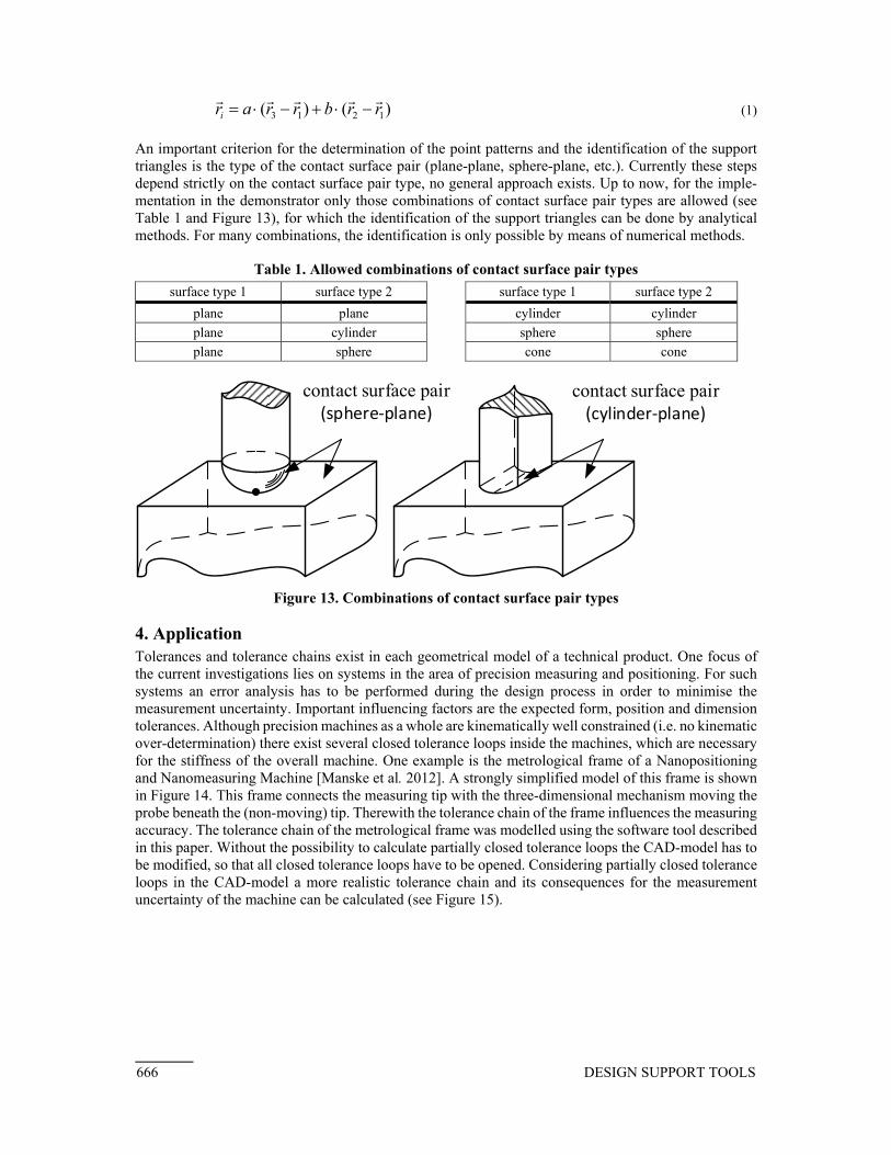
An important criterion for the determination of the point patterns and the identification of the support triangles is the type of the contact surface pair (plane-plane, sphere-plane, etc.). Currently these steps depend strictly on the contact surface pair type, no general approach exists. Up to now, for the imple-mentation in the demonstrator only those combinations of contact surface pair types are allowed (see Table 1 and Figure 13), for which the identification of the support triangles can be done by analytical methods. For many combinations, the identification is only possible by means of numerical methods.
Table 1. Allowed combinations of contact surface pair types
surface type 1 surface type 2 surface type 1 surface type 2
plane plane cylinder cylinder
plane cylinder sphere sphere
plane sphere cone cone
contact surface pair(sphere‐plane)
contact surface pair(cylinder‐plane)
Figure 13. Combinations of contact surface pair types
4. Application Tolerances and tolerance chains exist in each geometrical model of a technical product. One focus of the current investigations lies on systems in the area of precision measuring and positioning. For such systems an error analysis has to be performed during the design process in order to minimise the measurement uncertainty. Important influencing factors are the expected form, position and dimension tolerances. Although precision machines as a whole are kinematically well constrained (i.e. no kinematic over-determination) there exist several closed tolerance loops inside the machines, which are necessary for the stiffness of the overall machine. One example is the metrological frame of a Nanopositioning and Nanomeasuring Machine [Manske et al. 2012]. A strongly simplified model of this frame is shown in Figure 14. This frame connects the measuring tip with the three-dimensional mechanism moving the probe beneath the (non-moving) tip. Therewith the tolerance chain of the frame influences the measuring accuracy. The tolerance chain of the metrological frame was modelled using the software tool described in this paper. Without the possibility to calculate partially closed tolerance loops the CAD-model has to be modified, so that all closed tolerance loops have to be opened. Considering partially closed tolerance loops in the CAD-model a more realistic tolerance chain and its consequences for the measurement uncertainty of the machine can be calculated (see Figure 15).
666 DESIGN SUPPORT TOOLS

Figure 14. Metrological frame (model simplified)
worst‐case deviations (exaggerated visualisation) of the
active surface
Figure 15. Visualisation of the worst-case deviations
5. Conclusion and further steps In this paper a model and methods are presented, which enable tolerance representation and analysis directly in the CAD-system using vectorial tolerances. By direct representation of mathematically evaluable tolerances in the CAD-model the designer is better motivated to define the tolerances him-/ herself and can analyse the impact of deviations along the tolerance chain. A major motivation for the integration in the CAD-model is the similarity of the vectorial tolerance representation to the B-Rep (Boundary representation) description in current CAD-systems. In the paper furthermore the user-input is discussed. From a scientific point of view new in this paper is the possibility to analyse partially closed tolerance loops, the use of a reference system for vectorial tolerance analysis and the combination of vectorial tolerances with thermally- and load-induced deformations. When using existing CAT-tools only open tolerance chains can be considered. The developed approach is based on the statically determinate placement of a rigid body on discrete points, where the resulting line of action of the force lies within the triangle of the contact points. Assuming ideal rigid but deviation-affected components, the new placement-triangle can be determined. The re-alignment can be calculated with analytical methods for several contact surface pair types. For the investigations on partially closed tolerance loops as presented in this paper a number of simplifications were made. In the ongoing research these points will also be addressed, i.e. the simplifications will be dropped. Furthermore, the research will focus on consideration of form tolerances.
References Britten, W., Weber, C., "Transforming ISO 1101 Tolerances into Vectorial Tolerance Representations - A CAD-Based Approach", Global consistency of tolerances: Proceedings of the 6th CIRP International Seminar on Computer-Aided Tolerancing, van Houten, F., Kals, H. (eds.), University of Twente, Enschede, Netherlands, 22-24.03.1999, Springer, Dordrecht, London, 1999, pp. 93–100. Desrochers, A., "Geometrical Variations Management in a Multi-Disciplinary Environment with the Jacobian-Torsor Model", Models for Computer Aided Tolerancing in Design and Manufacturing: Selected Conference Papers from the 9th CIRP International Seminar on Computer-Aided Tolerancing, Davidson, J. K. (ed.), Arizona State University, Tempe, Arizona, USA, 10-12 April, 2005, Springer, Dordrecht, 2007, pp. 75–84.
DESIGN SUPPORT TOOLS 667

Gaunet, D., "3D Functional Tolerancing & Annotation: CATIA tools for Geometrical Product Specification", Geometric product specification and verification: Integration of functionality selected conference papers of the 7th CIRP International Seminar on Computer-Aided Tolerancing, Bourdet, P., Mathieu, L. (eds.), the École Normale Supérieure de Cachan, France, 24-25 April 2001, Kluwer Academic, Dordrecht, Boston, 2003, pp. 25–33. Geis, A., Husung, S., Oberänder, A., Weber, C., Adam, J., "Use of vectorial tolerances for direct representation and analysis in CAD-systems", 13th CIRP Conference on Computer Aided Tolerancing, 11.-14-05.2014., 2014a. Geis, A., Husung, S., Weber, C., Füßl, R., Manske, E., "Vectorial tolerances for the uncertainty analysis of precision measurement devices", Ilmenau Scientific Colloquium – Shaping the Future by Engineering, Scharff, P., Schneider, A. (eds.), Ilmenau, 08.-11.09.2014, Univ.-Verl., Ilmenau, 2014b. Husung, S., Oberänder, A., Weber, C., Geis, A., "Use of Vectorial Tolerances In CAD During the Design Process", 13th International Design Conference - DESIGN 2014, Marjanović, D., Štorga, M., Pavković, N., Bojčetić, N. (eds.), 19.-22.05.2014, Dubrovnik – Cavtat, Croatia, 2014. ISO 16792, "Technical product documentation -- Digital product definition data practices", 2010. Krimmel, O., Martinsen, K., "Industrial application of Vectorial Tolerancing to improve clamping of forged workpieces in machining", Global consistency of tolerances: Proceedings of the 6th CIRP International Seminar on Computer-Aided Tolerancing, van Houten, F., Kals, H. (eds.), University of Twente, Enschede, Netherlands, 22-24.03.1999, Springer, Dordrecht, London, 1999, pp. 101–110. Manske, E., Jäger, G., Hausotte, T., Füßl, R., "Recent developments and challenges of nanopositioning and nanomeasuring technology", Measurement Science and Technology, Vol. 23 No. 7, 2012, p. 74001. Requicha, A. A., "Representation of Tolerances in Solid Modelling: Issues and Alternative Approaches", Technical Memorandum, 1983. Stark, R., "Entwicklung eines mathematischen Toleranzmodells zur Integration in (3D-)CAD-Systeme", Dissertation, Universität des Saarlandes, Saarbrücken, 1994. Weber, C., Thome, O., Britten, W., "Improving computer aided tolerancing by using feature technology", 5th International Design Conference – DESIGN 1998, Marjanović, D. (ed.), 19.-22.05.1998, Dubrovnik, Croatia, 1998. Dr.-Ing. Stephan Husung, Technische Universität Ilmenau, Engineering Design Group Max-Planck-Ring 12, 98693 Ilmenau, Germany Email: [email protected]
668 DESIGN SUPPORT TOOLS