application of the vertical-float pbm-5 …seaplanes such that only minor pitching and rolling...
TRANSCRIPT

• ,33 L-
C *f'%iniI GD C-63-064
"ell% Jll
APPLICATION OF THE VERTICAL-FLOATCONCEPT TO A 1/29 SCALEPBM-5 SEAPLANE
MARCH 1963
MENERAL DYNAMIICS CONVAIRPost OffC ce Box 1950, San Dtego 12, California

GDC-63 -064
APPLICA 77ON OP THE VERTICAL-FLOAT
CONCEPT TO A 1/20 SCALE PBM-5 SEAPLANE
Contract NOw 62-0399-tTask Order No. 62-1
Final Report
March 1963
D. B. Dewey
J. T. Byrne
Hydrodynamics LaboratoryGeneral Dynamics/Convair
San Diego, California

CONTENTS
FOREW ORD ...................................... ii
INTRODUCTION .................................. iv
1 DESCRIPTION OF TESTS ....................... 1
2 TECHNICAL DISCUSSION ....................... 11
3 CONCLUSIONS ................................ 13

ILLUSTRATIONS
1. PBM Vertical-Float Model in Waves ........................ 2
2. Plot of Motions in Pitch ................................ 4
3. Plot of Motions in Roll .............................. 4
4. General Arrangement 1/20 Scale PBM Model With Vertical Floats 5
5. Comparative Motions in Pitch - 4-ft. Wavelengths ............. 7
6. Comparative Motions in Pitch - 19-ft. Wavelengths .......... 8
7. Comparative Motions in Roll - 4-ft. Wavelengths ............ 9
8. Comparative Motions in Roll - 19-ft. Wavelengths ............. 10
ii
FOREWORD
To more fully ensure the success of a proposed full-scale, vertical-float sea-
plane program, limited testing was conducted on a 1/20 scale PBM-5 seaplane
model. The model testing was done during the summer of 1962 at the towing
basin facility of Convair' s Hydrodynamic Laboratory and in San Diego bay,
adjacent to the laboratory.
An analytical study was made to determine the size and position of the
floats to be installed on this particular model. Tests were then conducted on
both the hull configuration and the stable, vertical-float version, and compara-
tive data was recorded for pitching, rolling, and heaving motions induced by
wave action.
The test results indicated that the vertical-float installation impressively
reduces pitching, rolling, and heaving motions of a seaplane over the range of
wave conditions for which it is designed.
iii

INTRODUCTION
In future ASW activities utilizing a seaplane, extended waterborne operation
will be necessary. During these waterborne periods, crew members will be
subject to the motions induced by the existing sea conditions. For effective
operations, these motions must be kept within the physical tolerances of the
human crew as well as the structural limits of the vehicle itself. One method
of controlling these motions is using vertical floats attached to the seaplane.
The vertical float concept was suggested by Mr. E. H. Handler, Bureau of
Naval Weapons, and it appears feasible for incorporation into a future GETOL,
VTOL, or STOL flight article.
Under subject contract, the General Dynamics/Convair Hydrodynamics
Laboratory modified a 1/20 scale PBM-5 model for testing in both regular and
irregular waves with vertical floats. Comparative tests were made without
floats in the normal PBM hullborne condition. No attempt was made under this
contract to provide for retraction or otherwise stowing the vertical floats.
A motion picture record was taken of selected portions of the tests and
should be considered as part of this report. The film clearly shows the dra-
matic motion reductions obtainable with the vertical float installation in waves
of various lengths. Only motion picture data was recorded for the outdoor testing.
iv
1 DESCRTPTION OF TESTS
Testing for the vertical-float system was done using a 1/20 scale model of the
PBM-5 seaplane furnished by BuWEPS for the program (see Figure 1). The
seaplane hull was properly ballasted to accurately simulate full-scale weight,
center-of-gravity position, and moments of inertia.
Model data is as follows:
a. Hull Configuration:
Gross Weight = 7.00 lb.
C.G. Location = 30% M.A.C. @ scale C.G. height
Ip = 0. 145 SL sq. ft.
IR = 0. 186 SL sq. ft.
b. Vertical Float Configuration:
Gross Weight = 7.6 lb.
C.G. (Hor.) = 30% M.A.C.
C.G. (Vert.) = 1.4 in. below hull configuration value
Each float supports 25% of gross weight
Roll waterplane area = 3.69 sq. in. (each float) @ 24.75 in. from (L
Pitch waterplane area = 6.70 sq. in. (each float) @ 18 in. from C.G.
I and IR was not determined
Damping plate size (each float) 5 in. x 5 in. (square)
Design waterline = 6.0 in. below hull keel

-i
Figures 2 aI 3 illustrate plots of motions in pitch and roll. System
natural periods were:
Without Damping With Damping
Pitch 4. 04 sec./cycle 5.20 sec. /cycle
Roll 3. 81 sec. /cycle 6. 20 sec. /cycle
Heave 1.10 sec. /cycle 4.55 sec. /cycle
Metacentric Height (Pitch) = 2.14 in. above C.G.
Metacentric Height (Roll) = 2.50 in. above C.G.
The wave height selected for all of the indoor tests was 3.0 in. At this
height, a wide range of wavelengths (3 to 20 ft.) can be generated and reliably
reproduced. Since the model is 1/20 scale, the corresponding full-scale wave
would be 5 ft. high and from 60 to 400 ft. long. For a Neuman distribution of
wave heights, a significant height of 5 ft. lies at the lower limit of sea-state 5.
Accordingly, the convenient model wave height selected has appropriate physi-
cal significance in that it approximates the wave conditions anticipated during
full-scale operations (sea-state 4).
All indoor model tests were conducted with zero wind velocity. It was felt
that the effect of a steady wind upon the dynamic response of the model would
be small and the additional effort unwarranted for these preliminary tests.
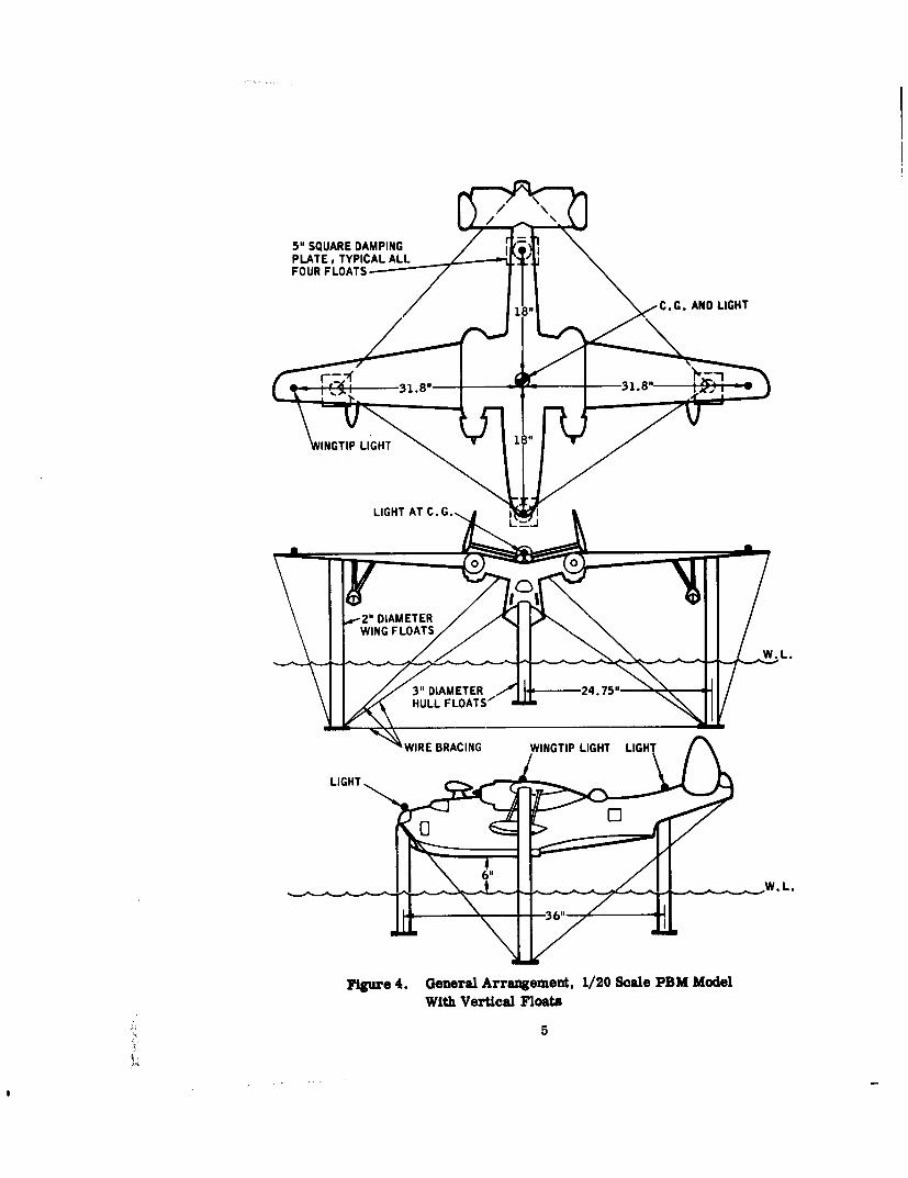
It was found necessary to have considerable metacentric height in order to
offset the destabilizing effect of structural flexibility of the relatively flimsy
model. The vertical floats were guyed to the hull with fine wire, the damping
effect of which was not determined. Position of wires is shown in Figure 4.
To maintain model position with respect to the data camera, the same system
of restraint was employed for both configurations. It consisted of a low-modulus
counterbalance using strings attached to the model and running horizontally
over pulleys to small weights hung in the tank. With the forward weight slightly
3

A C.G.x BOW
Y-INCHES 411 STERN-- -- HULL CONFIGURATION
-VERTICAL FLOATCONFIGURATION
10 1
WAVE LENGTH-FEET C MODEL SCALE)
Figure 2. Plot of Motions in Pitch
A C.G.
x PORT WING TIP* STARBOARDWING TIP
- - - HULL CONFIGURATION1(] - VERTICAL FLOAT
V-INCHES .CONFIGURATION
2
05 10 15 20
WAVE LENGTH-FEET (MODEL SCALE)
Figure 3. Plot of Motions in Roll
5" SQUARE DAMPINGPLATE, TYPICAL ALLFOUR FLOATS
181 C,.. AND LIGHT2-
"3." 31.8"
INTPLIGHT1
LIGHT AT C. G. I0 0
W. L.
S3" DIAMETER • 24.75"-HULL FLOATS/•
LIGHT, I,, BRACING• WINGTIP LIGHTLIH
611
I I
Figure 4. General Arrangement, 1/20 Scale PBM Model
With Vertical Floats
5

heavier, the model traveled forward until that weight rested on the bottom.
Wave action caused the model to drift slowly in the direction of wave motion.
Small lights on the model were photographed with the data camera. The lights
appeared as circular traces which were subsequently scaled to . calibration
grid, yielding the vertical double-amplitude displacements. Figures 5 through
8 show typical sequences of the data photos using this technique. Although data
was not taken for the model testing in San Diego bay, this portion was covered
by the colored motion picture film which forms a part of this report.
6
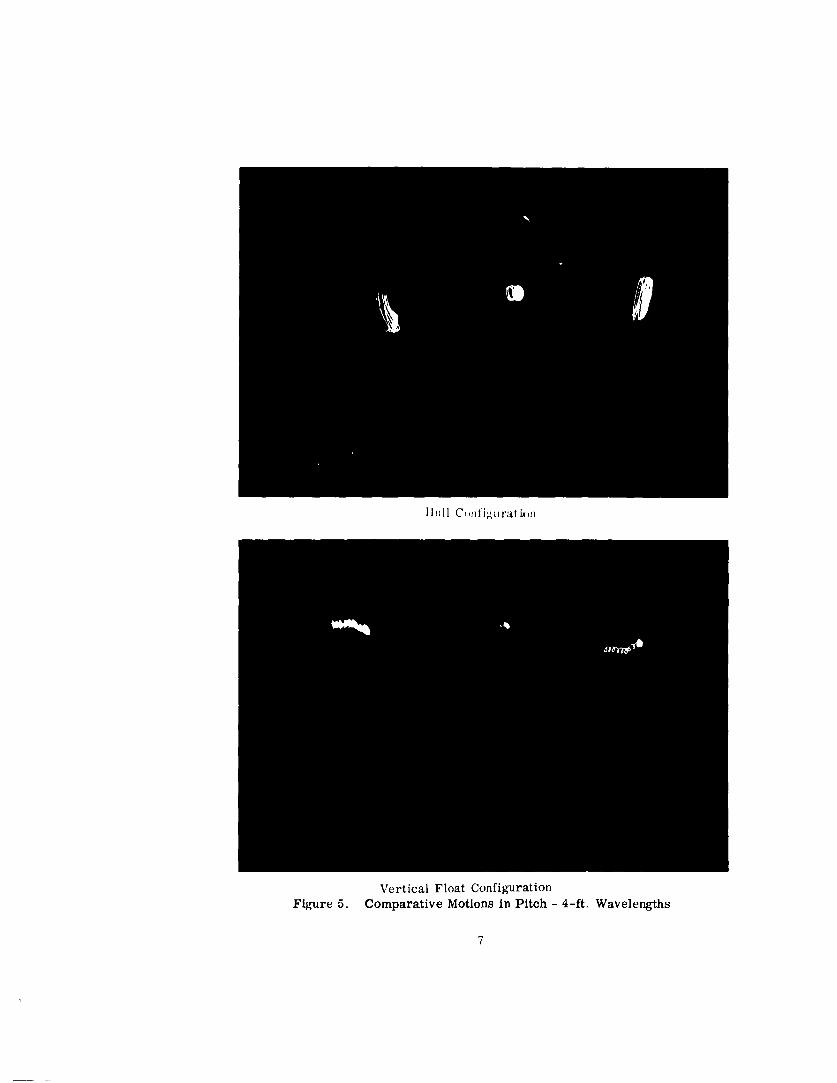
II llI C01111.Urat iujn
Vertical Float ConfigurationFigure 5. Comparative Motions in Pitch - 4-ft. Wavelengths
7

I Iii 11 ('on figurat iofl
Vertical Float ConfigurationFigure 6. Comparative Motions in Pitch - 19-ft. Wavelengths

I I tiI I C( i )Wi 1U rait i ()I
Vertical Float Configu rationFigure 7. Compa-rative Motions in Roll - 4-ft. Wavelengths

IILUIII C(,iftigurat imi
Vertical Float Con1figUrat ion
Figrure 8. Comparative Motions in Roll - 19-ft. Wavelengths
10

2 TECHNICAL DISCUSSION
During the entire testing phase, the major problems encountered were assoc-
iated with the structural flexibility of the PBM model. Accordingly, it was
necessary to incorporate an appropriate amount of metacentric height, GM,
to offset the destabilizing effect of the model flexibility. In view of the large
motion reduction already achieved, it appears qvestionable whether a smaller
GM will yield significantly smaller motions. Should a tethered, vertical-float
system be analyzed for the effect of wind loads, a large GM may be required
for static stability. Therefore, the concept of closely approaching neutral
stability in an operational system is questionable.
The actual design of the vertical-float system readily lent itself to rational
calculation. The test results themselves emphasize the effectiveness of a
properly designed vertical-float system for producing a stable platform.
In any system, optimum damping is desirable. However, even heavy over-
damping of the vertical float system produced excellent results. The tests
showed that adequate damping in the heave mode is definitely required since
the heaving oscillations of the vertical float configuration were extremely
large without the damping plates. Pitching and rolling motions of the vertical-
float model were almost nonexistent when compared to the violent thrashing of
the conventional hull in 3-in. waves.
Based on the results of the 1/20 scale model tcsting, the following recom-
mendations are made for the design and installation of vertical floats for the
11

full scale PBM-5 seaplane:
Estimated PBM-5 gross weight in the test configuration 45,689 lb.
Fuselage vertical float diameter 58 in. ID
Fuselage vertical float length below water level 117 in.
Wing vertical float diameter 44 in. ID
Wing vertical float length below water level 204 in.
Distance from center-line of airplane to wing float 400 in.
Distance from center of gravity to fuselage floats 299 in.
These locations for the vertical floats are partially dictated by the availability
of the PBM-5 structure capable of carrying the float loads.
The bottom damping plates will be circular 108-in. diameter. typical for
all floats.
12

3 CONCLUSIONS
The model tests indicated that a vertical float system can be designed for
seaplanes such that only minor pitching and rolling oscillations will result in
sea-state 4.
With the employment of an optimum vertical float system, seaplane heaving
will be of small magnitude in sea-state 4.
Seaplanes with 'ertical floats have low drift rates when compared to con-
ventional hulls.
The over-all results of the model tests are satisfactory enough to warrant
immediate full-scale investigation of this principle, including studies to de-
termine its effectiveness in ASW.
The most obvious application of a full-scale, vertical-float system is to a
a long-range VTOL or GETOL type vehicle. The ability, not only to land, but
to survive and operate on the surface of rough oceans has obvious advantages
in ASW or air-sea rescue operations. The vertical-float system appears to
be a promising solution to the on-the-water survivability of future seaplanes.
C2104975)
13