application of sliding mode control to switch-mode power supplies
TRANSCRIPT

1
APPLICATION OF SLIDING MODE CONTROL TOSWITCH-MODE POWER SUPPLIES
G. SPIAZZIDept. of Electronics and Informatics
and
P. MATTAVELLI, L. ROSSETTO, L. MALESANIDept. of Electrical Engineering
University of Padova
Via Gradenigo 6/a
35131 Padova - ITALY
Tel:(+39)49-828.7517 Fax:828.7599
Switch-mode power supplies represent a particular class of variable structure systems (VSS). Thus, they can take advantage of non-linear
control techniques developed for this class of systems. In this paper the so called sliding mode control is reviewed and its application to switch-
mode power supplies is discussed.
Sliding mode control extends the properties of hysteresis control to multi-variable environments, resulting in stability even for large supply
and load variations, good dynamic response and simple implementation.
Application to dc-dc converters, as well as rectifiers and inverters, is analyzed and provisions to overcome the inherent drawbacks of
sliding mode control, i.e. variable switching frequency and possible steady-state errors, are described. Experimental results are also reported,
which allow a comparison between the sliding mode approach and other standard control techniques, e.g. current-mode control, showing its
effectiveness.
1. Introduction
Control of switch-mode power supplies can be difficult, due to their intrinsic non linearity. In fact, control should ensuresystem stability in any operating condition and good static and dynamic performances in terms of rejection of inputvoltage disturbances (audiosusceptibility) and effects of load changes (output impedance). These characteristics, ofcourse, should be maintained in spite of large input voltage, output current, and even parameter variations (robustness).
A classical control approach relies on the knowledge of a linear small-signal model of the system to develop a suitableregulator.1 The design procedure is well known, but is generally not easy to account for the wide variation of systemparameters, because of the strong dependence of small-signal model parameters on the converter operating point. Thisaspect becomes even more problematic in rectifiers and/or inverters in which the operating point moves continuously,following the periodic input/output voltage variations.
Multiloop control techniques, like current-mode control, have greatly improved power converters behavior but thecontrol design remains difficult for high-order topologies, like those based on Cuk and Sepic schemes.2,3
A different approach, which complies with the non-linear nature of switch-mode power supplies, is represented by thesliding mode control, which is derived from the variable structure systems (VSS) theory.4,5 This control technique offersseveral advantages: stability even for large supply and load variations, robustness, good dynamic response and simpleimplementation. Its capabilities emerge especially in application to high-order converters, yielding improvedperformances as compared to classical control techniques.
In this paper, the sliding mode control is reviewed and its applications to switching power supply are investigated.Experimental results of different converter structures demonstrate the superior performances of this non-linear controltechnique as compared to standard control approaches.
2. Control of Variable Structure Systems: The Sliding Mode Approach
VSS are systems whose physical structure is changed intentionally during the time in accordance with a preset structurecontrol law. The instants at which the changing of the structure occur are determined by the current state of the system.

2
From this point of view, switch-mode power supplies represent a particular class of VSS, since their structure isperiodically changed by the action of controlled switches and diodes.6
2.1. An example: buck converter
To the purpose of explanation, consider the simple buck converter shown in Fig.1.7 In the continuous conduction modeoperation, the converter structure periodically changes by the action of the controlled switch S, giving rise to the twosubstructures shown in Fig.1. Considering as state variables the output voltage error δuo and its derivative, the systembehavior can be described by the following equations
( )
−σ⋅+−−=
=
.UULC1
LC
x
RC
xx
xx
*oi
122
21
(1)
in which σ is a discontinuous variable equal to 1 when the switch is ON and zero when the switch is OFF, and Uo* is theoutput voltage reference.
The phase trajectories corresponding to different values of control variable σ are shown in Fig.2. In both cases, thesystem evolution is a damped oscillation which starts from a point representing the system initial conditions and reachesan equilibrium point given by x1=Ui-Uo* and x2=0 for the case σ=1, and given by x1= -Uo* and x2=0 for the case σ=0.Note, however, that in this latter condition, the inductor current cannot become negative due to the presence of thefreewheeling diode. Thus, when this current reaches zero, the output capacitor is discharged to zero by the load resistanceonly, giving rise to a linear phase trajectory.
L
C R
+
-C
L
Switch ON Switch OFF
RU
iL
i Uo Uo
+
-
+
-
iL
C
L
D RUo
+
-
i L
+
-Ui
S
a) b)
Fig. 1 - DC-DC buck converter; a) subtopology during switch on-time,
b) subtopology during switch off-time.
x1
x2 σ=1σ=0
-Uo*
Fig. 2 - Phase trajectories corresponding to eq. (1) for different initial conditions.

3
2.2. Sliding mode control
Let us define the following functionψ τ= + ⋅x x1 2, (2)
which is a linear combination of the two state variables. In the phase plane, equation ψ=0 represents a line, calledsliding line, passing through the origin (which is the final equilibrium point for the system) with a slope equal to -1/τ.
We now define the following control strategyif
if
ψ β σ
ψ β σ
> + ⇒ =
< − ⇒ =
0
1,(3)
where β defines a suitable hysteresis band. In this way, the phase plane is divided in two regions separated by the slidingline, each associated to one of the two subtopologies defined by the switch status σ. Let us suppose that the system statusis in P, as shown in Fig.3. Since we are in the region ψ<-β, the switch is close and the motion occurs along a phasetrajectory corresponding to σ=1. When the system status crosses the line ψ=+ β, according to (3), the switch is turned offand the system status follows a phase trajectory corresponding to σ=1. Observing that the phase trajectories, in proximityof the sliding line, are directed toward the line itself, the resulting motion is made by continuous commutations around thesliding line, so that the system status is driven to the final equilibrium point.
σ=1
2x
iU x1
i =0L
σ=0
ψ=0
ψ=+β
ψ=−β
P
-Uo* -Uo
*
Fig. 3 - Sliding motion for the buck converter.
From this example, in the hypothesis of a suitable small value of β, two important conclusions arise
I: when the system is in the sliding mode, its evolution is independent of the circuit parameters. It depends only on thesliding line chosen. In the example shown in Fig.3 the dynamic is of the first order with a time constant equal to τ.
II: if N is the order of the original system, the dynamic of the controlled system in sliding mode has order N-1, sincethe state variables are constrained by the equation ψ=0.
Note that the switching frequency is determined by the amplitude of the hysteresis band β.The potentialities of this control technique in the application to switch-mode power supplies are now evident: it
exploits the intrinsic non-linear nature of these converters and it is able to provide dynamic behaviors that are differentfrom that of the substructures composing the system, and correspond to that of a reduced order system.
2.3. Conditions for sliding motion
In the simple case of the second-order system considered in the previous section, sliding mode control design requiresonly selection of parameter τ. Selection, must be done in order to ensure the following three constraints
(i) the hitting condition, which requires that the system trajectories cross the sliding line irrespective of their startingpoint in the phase plane;
(ii) the existence condition, which requires that the system trajectories near the sliding line (in both regions) aredirected toward the line itself;

4
(iii) the stability condition of the system motion on the sliding line (i.e. the motion must be toward the equilibriumpoint).
Another important consideration concerning physical systems is that not all points in the phase plane are reachable. Inthe previous example, since inductor current and output voltage are always non negative, the regions under the line x2 = -(x1+Uo* )/RC and to the left of line x1= -Uo* are left out.
3. Application of Sliding Mode Control to DC-DC Converters
3.1. Principle scheme
A basic sliding mode control scheme of dc-dc converters is shown in Fig.4.Let Ui and uCN be input and output voltages, respectively, iLi and uCj (i=1-r, j=r+1-N-1) the internal state variables of
the converter (inductor currents and capacitor voltages), and N the system order. According to the theory, all statevariables are sensed, and the corresponding errors xi (defined by difference to the steady-state values) are multiplied byproper gains Ki and added together to form the sliding function ψ. Then, hysteretic block HC control the switch so as tomaintain function ψ near to zero, thus we can write
ψ = ⋅ =∑K x = 0i i1
N
K xT . (4)
where K=[K1, K2,.., KN]T is the vector of sliding coefficients (T means transposition).This equation represents a hyperplane in the phase space passing through the origin (note that (2) is a particular case
of (4) for N=2, K1=τ /C and K2=1).This general scheme, although interesting in theory, is not practical. In fact, a control approach representing an
effective alternative to standard control techniques must have the following characteristics(i) simple design and implementation even for high-order converter topologies,(ii) constant switching frequency,(iii) no steady-state errors,(iv) possibility to implement a current limitation,
C
u *
x
ψHC
S
Ui
u
dc/dc converter
+ + + ++
K
Li Li
Li Li
CuCu
uC uC
K K1 r K K1r+
1
1
r
r
+r 1
+r 1
N
C
C
N
NN
x x x x1 r r + 1
* * * *
σ
N-1
N-1
N-1
N-1
Fig. 4 - Sliding mode control of dc-dc converters: principle scheme.
which are not satisfied in the scheme of Fig.4. In fact, for fourth order converters like Cuk and Sepic, it requires sensingof four state variables, which is not acceptable from practical point of view. Moreover, the hysteretic operation causes avariable switching frequency, while steady-state errors can arise from the fact that, in a practical implementation, all statevariable errors, except for the output voltage, are computed using high-pass filters,8 thus they have zero average value. Ifsliding function ψ, due to the hysteretic control, has non-zero average value, a steady-state output voltage errornecessarily appears. Lastly, switch current limitation is not implemented in the scheme shown.
As far as control complexity is concerned, it has been proved that excellent performances can be obtained even withreduced-order controllers, i.e. by sensing only one inductor current (the only inductor current in 2nd-order schemes like
5
buck, boost and buck-boost, and the input inductor current for 4th-order schemes, like Cuk and Sepic) and the outputvoltage.8-10 This corresponds to choose zero value for some coefficients Ki in (4).
3.2. Practical sliding mode controller of dc-dc converters
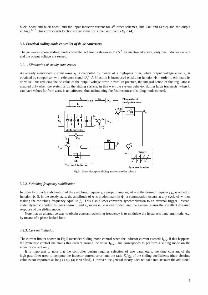
The general-purpose sliding mode controller scheme is shown in Fig.5.9 As mentioned above, only one inductor currentand the output voltage are sensed.
3.2.1. Elimination of steady-state errors
As already mentioned, current error xi is computed by means of a high-pass filter, while output voltage error xu isobtained by comparison with reference signal Uo
*. A PI action is introduced on sliding function ψ in order to eliminate itsdc value, thus reducing the dc value of the output voltage error to zero. In practice, the integral action of this regulator isenabled only when the system is on the sliding surface; in this way, the system behavior during large transients, when ψcan have values far from zero, is not affected, thus maintaining the fast response of sliding mode control.
K
K uC
U *
L
w Trigger
Synchronization
Elimination ofsteady-state error
PI
x
x
ψ
u
HC
S
i
Ui
I lim
SL
u
L
dc/dc converter
H.P.F.
Current Limitation
ψ ψ
f
ii
o
o
PI
σiL
Fig.5 - General purpose sliding mode controller scheme
3.2.2. Switching frequency stabilization
In order to provide stabilization of the switching frequency, a proper ramp signal w at the desired frequency fw is added tofunction ψ. If, in the steady state, the amplitude of w is predominant in ψf, a commutation occurs at any cycle of w, thusmaking the switching frequency equal to fw. This also allows converter synchronization to an external trigger. Instead,under dynamic conditions, error terms xi and xu increase, w is overridden, and the system retains the excellent dynamicresponse of the sliding mode.
Note that an alternative way to obtain constant switching frequency is to modulate the hysteresis band amplitude, e.g.by means of a phase locked loop.
3.2.3. Current limitation
The current limiter shown in Fig.5 overrides sliding mode control when the inductor current exceeds Ilim. If this happens,the hysteretic control maintains this current around the value Ilim. This corresponds to perform a sliding mode on theinductor current only.
It is important to note that the controller design requires selection of two parameters, the time constant of thehigh-pass filter used to compute the inductor current error, and the ratio Ki/Ku of the sliding coefficients (their absolutevalue is not important as long as eq. (4) is verified). However, the general theory does not take into account the additional
6
state variable of the filter. In order to overcome this problem, it is possible to derive a small-signal model of the slidingmode control, which takes into account also the filter time constant, so that the design parameters can be chosen fromsmall-signal analysis as in current-mode control.11
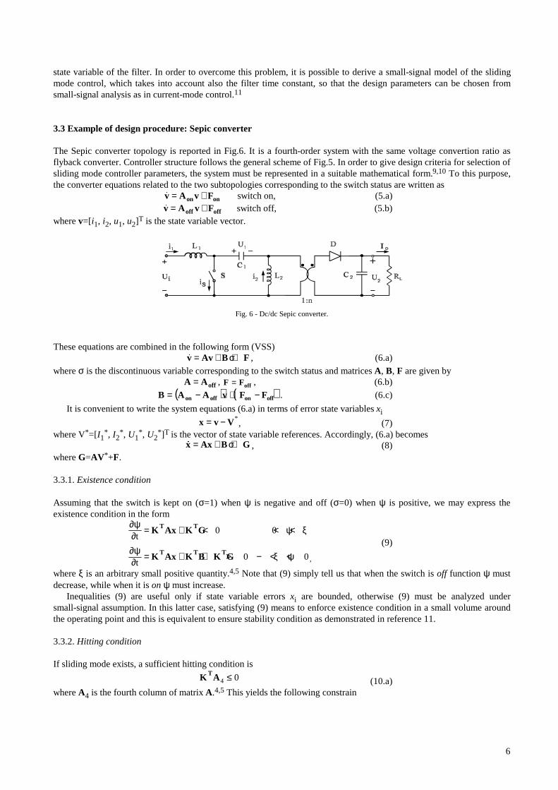
3.3 Example of design procedure: Sepic converter
The Sepic converter topology is reported in Fig.6. It is a fourth-order system with the same voltage convertion ratio asflyback converter. Controller structure follows the general scheme of Fig.5. In order to give design criteria for selection ofsliding mode controller parameters, the system must be represented in a suitable mathematical form.9,10 To this purpose,the converter equations related to the two subtopologies corresponding to the switch status are written as
v A v Fon on= + switch on, (5.a)v A v Foff off= + switch off, (5.b)
where v=[i1, i2, u1, u2]T is the state variable vector.
Fig. 6 - Dc/dc Sepic converter.
These equations are combined in the following form (VSS)v Av B F= + +σ , (6.a)
where σ is the discontinuous variable corresponding to the switch status and matrices A, B, F are given byA A off= , F Foff= , (6.b)
( ) ( )offonoffon FFvAAB −+−= . (6.c)
It is convenient to write the system equations (6.a) in terms of error state variables xi
x v V= − *, (7)
where V*=[I1*, I2
*, U1*, U2
*]T is the vector of state variable references. Accordingly, (6.a) becomesx Ax B G= + +σ , (8)
where G=AV *+F.
3.3.1. Existence condition
Assuming that the switch is kept on (σ=1) when ψ is negative and off (σ=0) when ψ is positive, we may express theexistence condition in the form
∂ψ∂ ψ ξ
∂ψ∂ ξ ψ
t
t
= + < < <
= + + > − < <
K Ax K G
K Ax K B K G
T T
T T T
0 0
0 0,
(9)
where ξ is an arbitrary small positive quantity.4,5 Note that (9) simply tell us that when the switch is off function ψ mustdecrease, while when it is on ψ must increase.
Inequalities (9) are useful only if state variable errors xi are bounded, otherwise (9) must be analyzed undersmall-signal assumption. In this latter case, satisfying (9) means to enforce existence condition in a small volume aroundthe operating point and this is equivalent to ensure stability condition as demonstrated in reference 11.
3.3.2. Hitting condition
If sliding mode exists, a sufficient hitting condition is
K AT4 0≤ (10.a)
where A4 is the fourth column of matrix A.4,5 This yields the following constrain

7
− − ≤KnL
KR C
i
1
u
L 20
(10.b)
3.3.3. Stability condition
This issue must be addressed taking into account the effect of the time constant τHPF of the high-pass filter needed toextract the inductor current error. To this purpose the small-signal analysis carried out in reference 11 allows to deriveprecise constraints on controller parameters for the three basic converter structures (buck, boost, buck-boost). For higherorder converters, like Sepic, the approach outlined in reference 11 is valuable to observe the effect of controllerparameter variations on the system dynamic. For example, Fig.7 shows the root locus of the closed-loop Sepic converterresulting from different values of the filter time constant. As we can see, too low values cause real poles P1 and P2 tobecome complex or even to cross the imaginary axis.
3.3.4. PI compensator
As already mentioned in paragraph 3.2.1, the integral action of PI regulator on variable ψ is enabled only when thesystem is on the sliding surface. Since its aim is to cancel the steady-state error on the output voltage, its time constant τPIcan be chosen big enough not to affect the system stability. Moreover, it does not affect system dynamic during largetransients.
3.3.5. Ramp signal wAs far as the ramp signal w is concerned, its amplitude is selected by taking into account the slope of function ψPI and
the hysteresis band amplitude, so that function ψf hits the lower part of the hysteresis band at the end of the ramp, causingthe commutation. The aim of this external ramp is to force a constant switching frequency in spite of duty-cycle variations(i.e. input and/or output voltage changes) and load variations.
As an example, Fig.8 shows simulated waveforms of ramp w, and ψPI, ψf signals. From waveform analyses, we canfind that the slope Se of the external ramp must satisfy the following inequality
SBT
Ses
r> −∆δ , (11)
in which ∆B represent the hysteresis amplitude and Sr is the slope of function ψPI during switch on-time. This latter, isgiven by
pu2
oi
1
ir KK
C
IK
L
US ⋅
−=
(12)
where Kp is the gain of the proportional part of PI regulator.It is worthy to note that, in the presence of an external ramp, signal ψPI must have a non zero average value in order to
accomodate for the desired converter duty-cycle (see Fig.8).
Imag
Real
P1 P2
P3
P4
Fig. 7 - Root locus of closed-loop system for variation of
low-pass filter time constant of the Sepic converter.

8
Fig. 8 - simulated waveforms of ramp w, and ψPI, ψf signals.
4. Application of Sliding Mode Control to AC-DC Converters
With the ever increasing demand for power quality from the utility grid, power factor correction (PFC) is becoming abasic requirement for switch-mode power supplies. High quality rectifiers are used to interface ac line and dc load andappear to the line as a resistive load, so achieving unity power factor even in presence of distorted line voltage.12
An inherent limitation of these converters is their slow dynamic response. In fact, sinusoidal input current means largeinput power fluctuations at twice the line frequency, resulting in low-frequency output voltage ripple, which cannot becorrected by the control, otherwise input current waveform is affected. Big output filter capacitors must therefore beadopted in order to limit the voltage ripple, which further reduces the bandwidth of the voltage control loop. Accordingly,these converters are normally used as pre-regulators, their output performances being below the requirements of standardpower supplies.
In practice, this bandwidth limitation can be overcome if some input current distortion is accepted (within the limitsposed by the standards, e.g. IEC 555-2), provided that this results in smaller power fluctuation. From this point of view,sliding mode control is very powerful, since it can provide an optimal trade-off between the needs for increasing responsespeed and reducing input current distortion and output voltage ripple.
A high-quality rectifier based on Cuk topology with sliding mode control is shown in Fig.9.
R
KK
u
i
LL
N N
u
i
i
i* U*
I
+
SlidingMode
Controller
CurrentReferenceAdjustment
Ci
1
1
1 2
2
00
0
ui
i1
1
i u
0+ - + -
+
-
σ
x x+ +
+
-
+
-1
+
-
u 0ψ
++
-
I LIM
SwitchCurrentLimiter
*
RLur
+
-
Fig. 9 - High-quality rectifier based on Cuk converter with sliding mode control.
In this scheme, including an insulation transformer, reference values (i1*, Uo
*) are required for both state variables.However, while Uo
* is an input variable for the control, i1* must be evaluated as a function of voltage error xu. For this
9
purpose, similarly to the case of current-mode control, an error amplifier Ri is used to determine reference amplitude I1*,
which is then multiplied by rectified voltage signal uR to obtain current reference i1*. As usual, the band of regulator Ri is
kept well below the line frequency to avoid input current distortion. However, during transient conditions, if the systemremains in sliding mode, the large output voltage error forces, via block Ku, a large current error, causing a temporary lostof the sinusoidal shape of input current. In this way, a fast output voltage recovery to nominal conditions is obtained.
If coefficients Ki and Ku are chosen properly, we gain additional advantages. First, in the steady-state the controllertends to maintain the minimum errors xi and xu which are consistent with energy balance condition. Second, the value ofthe coefficients also determines the relative amplitudes of voltage and current errors. This means that varying the ratioKi/Ku we can choose the best trade off between input current distortion and fast output voltage response.
The input current limiter is implemented in the usual manner as for dc-dc converter controllers.
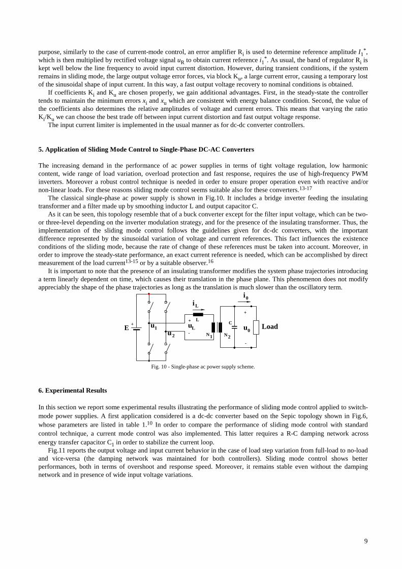
5. Application of Sliding Mode Control to Single-Phase DC-AC Converters
The increasing demand in the performance of ac power supplies in terms of tight voltage regulation, low harmoniccontent, wide range of load variation, overload protection and fast response, requires the use of high-frequency PWMinverters. Moreover a robust control technique is needed in order to ensure proper operation even with reactive and/ornon-linear loads. For these reasons sliding mode control seems suitable also for these converters.13-17
The classical single-phase ac power supply is shown in Fig.10. It includes a bridge inverter feeding the insulatingtransformer and a filter made up by smoothing inductor L and output capacitor C.
As it can be seen, this topology resemble that of a buck converter except for the filter input voltage, which can be two-or three-level depending on the inverter modulation strategy, and for the presence of the insulating transformer. Thus, theimplementation of the sliding mode control follows the guidelines given for dc-dc converters, with the importantdifference represented by the sinusoidal variation of voltage and current references. This fact influences the existenceconditions of the sliding mode, because the rate of change of these references must be taken into account. Moreover, inorder to improve the steady-state performance, an exact current reference is needed, which can be accomplished by directmeasurement of the load current13-15 or by a suitable observer.16
It is important to note that the presence of an insulating transformer modifies the system phase trajectories introducinga term linearly dependent on time, which causes their translation in the phase plane. This phenomenon does not modifyappreciably the shape of the phase trajectories as long as the translation is much slower than the oscillatory term.
+ uu
1
2
L
E u0
+
-
iLi
0
LoaduL
+
- N N1 2
C
Fig. 10 - Single-phase ac power supply scheme.
6. Experimental Results
In this section we report some experimental results illustrating the performance of sliding mode control applied to switch-mode power supplies. A first application considered is a dc-dc converter based on the Sepic topology shown in Fig.6,whose parameters are listed in table 1.10 In order to compare the performance of sliding mode control with standardcontrol technique, a current mode control was also implemented. This latter requires a R-C damping network acrossenergy transfer capacitor C1 in order to stabilize the current loop.
Fig.11 reports the output voltage and input current behavior in the case of load step variation from full-load to no-loadand vice-versa (the damping network was maintained for both controllers). Sliding mode control shows betterperformances, both in terms of overshoot and response speed. Moreover, it remains stable even without the dampingnetwork and in presence of wide input voltage variations.

10
Table 1. Parameter values of the DC/DC Sepic converter.
Ui = 15V U2 = 20V fs = 50kHz n = 1.5 RL = 20Ω
L1 = 0.7mH L2 = 0.38mH C1 = 6.8µF C2 = 100µF
Ki = 1.1 Ku = 1 τHPF = 0.5ms τPI = 0.5ms
As an example of what we can obtain in terms of response speed of an ac-dc converter with power factor correction,the scheme of Fig.9 was implemented and tested. Its parameters are reported in table 2.
Table 2. Parameter values of the AC/DC converter of Fig.9.
Ui = 100Vpeak Uo = 15V fs = 60kHz N1/N2 = 10 RL = 5Ω
L1 = 4mH L2 = 40µH C1 = 0.22µF C2 = 100µF Co = 10000µF
u
i 1
2
19
20
21
0
1
2
A
V
u
i 1
220
21
19
0
1
2
A
V
0 4 8 12 16 ms
a)
b)
Fig. 11 - Output voltage and input current waveforms of the Sepic converter for load step variation:
a) sliding mode control, b) current mode control.
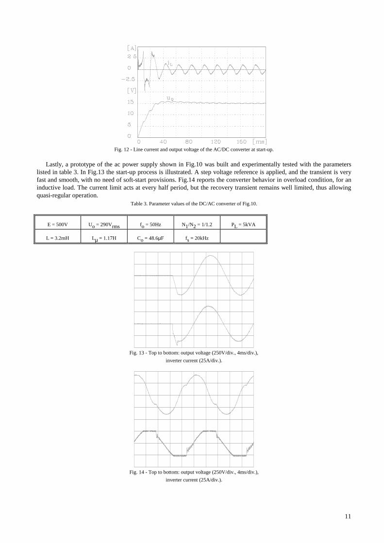
Fig.12 shows line current and output voltage at start-up: the current distortion during the transient, caused by the higherror voltage xu, is the price for the faster output dynamic. In the steady state, however, a good current waveform isachieved.
11
Fig. 12 - Line current and output voltage of the AC/DC converter at start-up.
Lastly, a prototype of the ac power supply shown in Fig.10 was built and experimentally tested with the parameterslisted in table 3. In Fig.13 the start-up process is illustrated. A step voltage reference is applied, and the transient is veryfast and smooth, with no need of soft-start provisions. Fig.14 reports the converter behavior in overload condition, for aninductive load. The current limit acts at every half period, but the recovery transient remains well limited, thus allowingquasi-regular operation.
Table 3. Parameter values of the DC/AC converter of Fig.10.
E = 500V Uo = 290Vrms fo = 50Hz N1/N2 = 1/1.2 PL = 5kVA
L = 3.2mH Lµ = 1.17H Co = 48.6µF fs = 20kHz
Fig. 13 - Top to bottom: output voltage (250V/div., 4ms/div.),
inverter current (25A/div.).
Fig. 14 - Top to bottom: output voltage (250V/div., 4ms/div.),
inverter current (25A/div.).
12
7. Conclusions
Control techniques of variable structure systems find a natural application to switch-mode power supplies. In particular,the sliding mode control represents a powerful tool to enhance performances of power converters.
Sliding mode control is able to ensure system stability even for large supply and load variations, good dynamicresponse and simple implementation, even for high-order converters. These feautures make this control technique a validalternative to standard control approaches like current-mode control.
Application to dc-dc converters, as well as rectifiers and inverters, is analyzed and provisions to overcome theinherent drawbacks of sliding mode control, i.e. variable switching frequency and possible steady-state errors, aredescribed.
Experimental results are also reported, showing the effectiveness of this control technique.
Acknowledgements
The authors would like to thank Mr. R. Sartorello for his support in the experimental activities.
References
1. R. D Middlebrook, S. Cuk, Advances in Switched-Mode Power Conversion, TESLAco, Vol. I and II, Pasadina (CA), 1983, pp.73-89.
2. R.Redl, N.Sokal, "Current-Mode control, five different types, used with the three basic classes of power converters: small-signalAC and large-signal DC characterization, stability requirements, and implementation of practical circuits", IEEE-PESC, 1985,pp. 771-785.
3. R. B. Ridley, B. H. Cho, F. C. Y. Lee, "Analysis and interpretation of loop gains of multiloop-controlled switching regulators",IEEE Transaction on Power Electronics, vol.3, n. 4, October 1988, pp. 489-498.
4. V. I. Utkin, Sliding Mode and Their Application in Variable Structure Systems, MIR Publischer, Moscow, 1974 (EnglishTranslation 1978).
5. U. Itkis, Control Systems of Variable Structure, John Wiley & Sons, New York, 1976. 6. R.Venkataramanan, A.Sabanovic and S.Cuk: "Sliding-mode control of DC-to-DC converters," IECON Conf. Rec, 1985. 7. F.Bilalovic, O.Music and A.Sabanovic: "Buck converter regulator operating in the sliding mode," PCI Conf. Rec., 1983,
pp.331-340. 8. L.Malesani, L.Rossetto, G.Spiazzi, P.Tenti, "Performance optimization of Cuk converters by sliding-mode control," in Applied
Power Electronics Conference Proc. (APEC), 1992, pp.395-402. 9. P. Mattavelli, L. Rossetto, G. Spiazzi, P. Tenti, "General-purpose sliding-mode controller for DC/DC converter applications",
Proc. of Power Electronics Specialists Conf. (PESC), Seattle, June 1993, pp.609-615.10. P. Mattavelli, L. Rossetto, G. Spiazzi, P. Tenti, "Sliding mode control of SEPIC converters", Proc. of European Space Power
Conf. (ESPC), Graz, August 1993, pp.173-178.11. P. Mattavelli, L. Rossetto, G. Spiazzi, "Small-signal analysis of DC-DC converters with sliding mode control", Proc. of Applied
Power Electronics Conf. (APEC), Dallas, March 1995, pp.153-159.12. S. Freeland, Input Current Shaping for Single-Phase AC-DC Power Converters, PH.D. Thesis, Part II, California Institute of
Technology (CalTech), 1988.13. J. Fernando Silva, Sonia S. Paulo, "Fixed frequency sliding mode modulator for current mode PWM inverters", in Power
Electronics Specialists Conf. Proc. (PESC), 1993, pp. 623-629.14. M.Carpita, P.Farina, S. Tenconi, A single-phase, sliding mode controlled inverter with three levels output voltage for UPS or
power conditioning applications", in European Power Electronics Conf. Proc., 1993, pp. 272-277. 15. L. Malesani, L. Rossetto, G. Spiazzi, A. Zuccato, "An AC power supply with sliding-mode control", Proc. of Industry
Application Society Conf. (IAS), Toronto, October 1993, pp.1115-1121. 16. H. Pinheiro, A. S. Martins, J. R. Pinheiro, "A sliding mode controller in single phase voltage source inverters", Proc. of
International Conference on Industrial Electronics, Control, and Instrumentation (IECON), 1994, pp. 394-398. 17. N. Sabanovic, A. Sabanovic, K. Ohnishi, "Sliding mode control of three-phase switching converters", Proc. of International
Conference on Industrial Electronics, Control, and Instrumentation (IECON), San Diego, 1992, pp.319-325.