application of rigid multi-body system …mech-ing.com/journal/archive/2011/4/40_gasper...
TRANSCRIPT
APPLICATION OF RIGID MULTI-BODY SYSTEM MODELLING TO DETERMINATION OF PASSENGER-CAR AND TRAILER COMBINATION
LATERAL STABILITY
Dr. Mech. Eng. Šušteršič G. 1, Dr. Mech. Eng. Ambrož M. 1, Prof. Dr. Mech. Eng. Prebil I.1 Faculty of Mechanical Engineering – University of Ljubljana, Slovenia 1
Abstract: The dynamic behaviour of a road vehicle is a very important aspect of vehicle safety. The term ‘lateral stability’ or ‘snaking’ implies damping characteristics of the yaw oscillation of towing-vehicle-trailer combinations, excited by an unsettling disturbance impulse. These disturbances may result form external inputs such as unevenness in road surface or gusts of wind, but may also be caused by driver action during evasive manoeuvres or actions in normal driving such as changing lanes or overtaking. Several models have been found in the literature enabling insight into this phenomenon, most of them based on the yaw-plane dynamics of the vehicle-trailer combination. These give some useful insight into the nature of the problem. This paper presents the Rigid Multi-Body System (RMBS) dynamics modelling approach to vehicle-trailer high velocity lateral dynamic (in)stability determination. Firstly, methods for determination of vehicle and trailer parameters, geometric as well as dynamic and kinematic ones, are presented. These parameters are used in the RMBS model of the vehicle-trailer combinations presented further in the paper. Further on, the experimental setup of the actual vehicle-trailer combination is presented, with the experimental equipment and procedures described as well. Finally, the results of the RMBS-model simulations are presented next to results of experimental investigation and comparison is given between the two.
Keywords: VEHICLE-TRAILER COMBINATION, LATERAL STABILITY, DYNAMICS, RIGID MULTI-BODY SYSTEMS
1 Introduction The significance of the presence of a trailer attached to a
vehicle for vehicle dynamics shall be illustrated in this paper. Due to the geometrical and mechanical complexity of the vehicle-trailer system, where eventual large displacements and rotations inevitably lead to high non-linearity, we believe the presented approach to be among the appropriate methods for detailed analyses.
In this paper, we present an approach utilizing the MBS modelling of a vehicle-trailer system dynamics. The mechanical model of the vehicle-trailer system shall be described as a system of rigid bodies interconnected through rotational, translational and spherical kinematic constraints, springs and dampers, all of which govern the relative motion of bodies in the system. The modelled vehicle shall be a four-wheeled passenger car with front wheels individually suspended (MacPherson strut), and the rear wheels suspended by a semi-independent twist axle system. Damping and bump stop elements of suspensions have non-linear characteristics and are modelled as such. The steering mechanism of a rack and pinion type is implemented on the front axis.
The mechanical model of the vehicle shall consist of 11 bodies. Each body with its own mass and inertia characteristics obtained either by measuring or geometrical modelling. All mass and inertia characteristics of the bodies in the mechanical model of the vehicle, except the characteristics of a self-supporting body, are obtained by geometrical modelling. The spring is modelled with a linear spring characteristic, whereas the damper is modelled with the use of a measured force velocity relationship
and has a non-linear characteristic. Two additional elements that contribute significantly to the vehicle response are the bump stop and the work stroke limiter of the damper. The bump stop is also modelled through the use of a non-linear force deflection relationship obtained through measurement.
Several simulations of the vehicle-trailer system shall be made with the implementation of computer codes developed for the general purpose of MBS dynamics modelling. Vehicle-trailer system dynamic responses shall be compared against each other and against measurement results, where appropriate. The use of simulation tools enables us to carry out even simulations of situations not generally executable due to the threat of damage to researchers and the equipment. Simulations of events that pose no threat to researchers and the equipment shall be verified experimentally. Presented shall be simulation examples of the vehicle-trailer combination with an inappropriately loaded trailer.
2 Detailed MBS model The implemented MBS mechanical model is fairly complex
and highly non-linear as suspension characteristics, apart from the bushings, were taken into consideration with their actual characteristics (measured data) rather than their linearized values, whenever possible.
2.1 Geometric model (vehicle, trailer)
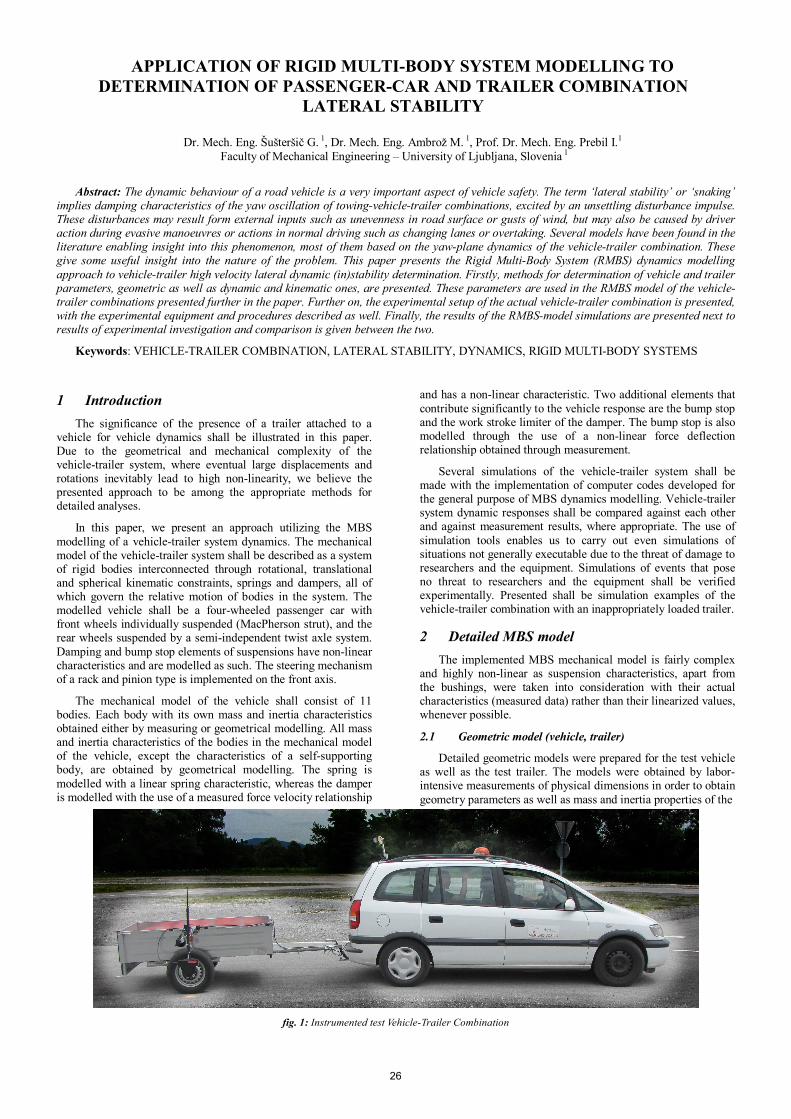
Detailed geometric models were prepared for the test vehicle as well as the test trailer. The models were obtained by labor-intensive measurements of physical dimensions in order to obtain geometry parameters as well as mass and inertia properties of the
fig. 1: Instrumented test Vehicle-Trailer Combination
26

modelled parts. The sprung weight and inertia values were obtained from data in the CARAT database [1].
fig. 2: Geometric model of the front suspension
fig. 3: Geometric model of the rear suspension
fig. 4: Geometric model of the vehicle
fig. 5: Geometric model of the trailer
2.2 Suspension parameters (Vehicle front and rear)
There are many elements that determine the vehicle dynamic response. The ones considered in the MBS model of the vehicle are a spring, damper and bumpstop element and are all depicted in fig. 6. To determine parameters of each element that were later used in mathematical models of the elements, several measurements were carried out. The measured data are shown in fig. 7 – fig. 9.
2.3 Suspension parameters (Trailer)
Torsional suspension with a rubber element provides both springing and damping. Determination of the characteristics is thus not as straightforward as it was with the vehicle suspension.
We decided to use a linear mathematical model of the trailer suspension. We can describe it by using the following equation
2 0J J k . (1)
fig. 6: Elements of vehicle suspension
Bump_Stop_Stiffness
0
2000
4000
6000
8000
10000
0 10 20 30 40 50Deformation [mm]
Forc
e [N
]
fig. 7: Bumpstop spring characteristic
Spring_Stiffness_Rear
y = 23.266x + 4.7034R2 = 1
0500
1000150020002500
0 20 40 60 80 100Deformation [mm]
Forc
e [N
]
fig. 8: Spring stiffness
fig. 9: Damper characteristic
Several simple experiments were carried out in order to obtain the parameters needed for the mathematical model of the trailer suspension described by the equation (1).
To determine the spring coefficient k, we applied several values of the torsional moment to the trailing arm (via a set of weights applied on a lever arm) and measured the rotation induced by it, as defigured in fig. 10.
To determine the damping coefficient, we induced oscillation of the suspension by deflecting it out of the equilibrium position and letting it oscillate until standstill, fig. 11. A wire of a wire
27
transducer was wound around a circular part of the trailing arm that is coaxial with the main axis of the trailing arm. By measuring the length of the wire wound on this circular part and by knowing its diameter, the angle of rotation of the trailing arm is readily determinable.
fig. 10: Results of spring characteristic measurement
fig. 11: Deflected suspension oscillating to standstill
In addition to suspension parameters, some other parameters such as tyre model parameters and the vehicle engine torque curve also needed to be determined and provided to the MBS modeller.
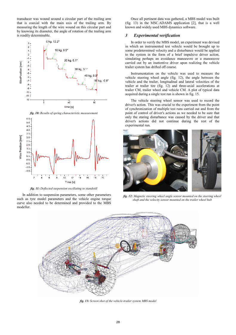
Once all pertinent data was gathered, a MBS model was built (fig. 13) in the MSC.ADAMS application [2], that is a well known and widely used MBS dynamics software.
3 Experimental verification In order to verify the MBS model, an experiment was devised
in which an instrumented test vehicle would be brought up to some predetermined velocity and a disturbance would be applied to the system in the form of a brief impulsive driver action, simulating perhaps an avoidance manoeuvre or a manoeuvre carried out by an inattentive driver upon realizing the vehicle trailer system has drifted off course.
Instrumentation on the vehicle was used to measure the vehicle steering wheel angle (fig. 12), the angle between the vehicle and the trailer, longitudinal and lateral velocities of the trailer at trailer tire (fig. 12) and three-axial accelerations at trailer CM, trailer wheel and vehicle CM. A plot of typical data acquired during a single test run is shown in fig. 15.
The vehicle steering wheel sensor was used to record the driver's action. This was crucial to the experiment from the point of synchronization of multiple test runs carried out and from the point of control of driver's actions as we needed to be sure that only the staring disturbance was caused by the driver and that driver's actions did not continue during the rest of the experimental run.
fig. 12: Magnetic steering wheel angle sensor mounted on the steering wheel
shaft and the velocity sensor mounted on the trailer wheel hub
fig. 13: Screen shot of the vehicle-trailer system MBS model
28

fig. 14: Simulation results at under and over critical velocities (100 to 110 km/h)
The horizontal plane angle between the vehicle and the trailer was measured as it is one of the most evident parameters that speaks clearly of the system stability. If the amplitudes of angle oscillations continue to reduce with time, the system is clearly stable, while if they increase, the system is clearly unstable.
Longitudinal vehicle-trailer system velocity sensor is crucial in determining the velocity the vehicle has gained at the onset of the driver’s impulsive action. The lateral velocity of the trailer is another parameter that can be used to determine the level of stability of the system.
Vehicle and trailer accelerations can be utilized for the same purpose as well. Data from the accelerometers measuring lateral accelerations of the vehicle and trailer carry most significance.
fig. 15: Some measured data during a single test run
4 Results and discussion Both models as well as measurements referenced by other
authors [3, 4] show that trailer load position and arrangement greatly influence the vehicle-trailer system stability. When incorrectly loaded, it is perfectly possible for the vehicle-trailer combination to become unstable at road legal velocities, fig. 14.
Due to safety considerations, the experiments were not carried out at velocities close to critical. Due to limitations of the test course, the test velocities were even considerably lower than the critical velocity. The comparison of simulations and measurements could thus not be done by comparison of critical velocities, but rather by comparison of the system response.
We implemented the measured steering wheel angle, shown in fig. 15 as input to numerical simulation, and compared the simulated response to the measured one. We have thus managed to show the MBS model results to be in close agreement with the measured data. Both longitudinal and lateral velocities of the trailer at the location of the velocity sensor bear close resemblance (fig. 16 and fig. 17). Consequently, we are confident that the model can be used to predict the critical velocity at which the onset of system instability occurs.
fig. 16: Comparison of measured and simulated trailer lateral velocities
fig. 17: Comparison of measured and simulated trailer lateral velocities
5 Conclusion Several approaches to vehicle dynamics modelling can be
implemented with the purpose of vehicle dynamic instability determination. One of them is described in this paper. The MBS model can be readily implemented for various other analyses as well. The results of the MBS model simulations were compared against the measured results.
A measurement system for measuring relevant kinematic quantities on a vehicle-trailer system has been devised and used to acquire the data. It is applicable in research of various scenarios of driving a vehicle-trailer system and can thus be used in future research in this field.
6 References [1] H. Burg, "CARAT (Computer Aided Reconstruction of
Accidents in Traffic)," IbB Informatik GmbH, 1997-2010.
[2] "MSC.ADAMS," MSC.Software Corporation, 2007. [3] A. Hac, D. Fulk, and H. Chen, “Stability and Control
Considerations of Vehicle-Trailer Combination,” SAE TECHNICAL PAPER SERIES, no. 2008-01-1228, pp. 1-15, 2008.
[4] C. J. Killer, “The Dynamics of Towed Wehicles,” Final year project, Department of Mechanical Engineering, University of Bath, Bath, 2003.
29