application of nonlinear-modulation technique for the
TRANSCRIPT

W. Zhou,1 Y. Shen,2 L. Xiao,1 and W. Qu3
Application of Nonlinear-ModulationTechnique for the Detection of BoltLoosening in Frame Structure
Reference
Zhou, W., Shen, Y., Xiao, L., and Qu, W., “Application of Nonlinear-Modulation Technique for the Detection
of Bolt Loosening in Frame Structure,” Journal of Testing and Evaluation, Vol. 44, No. 2, 2016, pp. 967–
975, doi:10.1520/JTE20150321. ISSN 0090-3973
ABSTRACT
Bolted joints are susceptible to loosening in the vibrational service environment, which
would adversely affect the joint structure integrity. In this work, a nonlinear-modulation
approach was explored as a potential method to effectively detect bolt loosening at its early
stage, by analyzing the modulation spectrum that arises from the nonlinear vibrations
caused by the loosening bolts. To reveal the mechanism of nonlinear modulation, a
mathematical model was developed. An effective energy-based damage index was
formulated based on the high-frequency intrinsic mode functions (IMF), which contains
modulation components processed by empirical mode decomposition (EMD). Vibration
tests on a frame structure were carried out to investigate the feasibility of the proposed
method. The experimental results demonstrated that modulation occurred in the high-
frequency region of response signals; it was found that the energy-based damage index can
accurately detect nonlinear damage caused by bolt loosening with superb sensitivity.
Keywords
bolt loosening, damage detection, vibration modulation, empirical mode decomposition, energy damage
index, structural health monitoring
Introduction
Bolted joints are widely used to connect structural components in mechanical and aerospace struc-
tures due to ease of assemblage and dismantlement. However, bolt loosening, induced by cyclic
loading and environmental factors, would result in serious destruction of the integrity of struc-
tures. Thus, an effective approach for detecting bolt loosening is of great application significance
in structural health monitoring (SHM) and non-destructive evaluation (NDE).
Manuscript received July 30, 2015;
accepted for publication January 6,
2016; published online January 29, 2016.
1 Department of Engineering Mechanics,
Wuhan Univ., Wuhan, 430072 China.
2 Department of Aerospace Engineering,
Univ. of Michigan, Ann Arbor, MI 48109.
3 Department of Engineering Mechanics,
Wuhan Univ., Wuhan 430072
(Corresponding author),
e-mail: [email protected]
Copyright VC 2016 by ASTM International, 100 Barr Harbor Drive, PO Box C700, West Conshohocken, PA 19428-2959. 967
Journal of Testing and Evaluation
doi:10.1520/JTE20150321 / Vol. 44 / No. 2 / March 2016 / available online at www.astm.org

Nowadays, methods of loosening detection have been
studied by many researchers. Among various damage detection
methods, global methods based on the analysis of vibration data
have received considerable attention. Hartwigsen et al. [1]
reported an experimental study to quantify the non-linear
effects of a typical shear lap joint. The tests revealed several
important influences on the effective stiffness and damping of
the lap joints. Milanese et al. [2] developed a joint loosening
model to simulate the dynamic response to a stationary Gaus-
sian excitation. Huda [3] proposed a vibration test methodology
using an impulse response excited by laser ablation and intro-
duced a damage index based on the Recognition Taguchi
method to detect bolted joint loosening. Shiryayev et al. [4]
developed an alternative parameter estimation approach for the
adjusted Iwan, which was identified as a promising candidate
for representing joint dynamics. Yu Luan et al. [5] proposed a
nonlinear dynamic model with bi-linear springs validated for
bolted pipe structures. Finally, experiments and numerical sim-
ulations are performed. Amerini et al. [6] presented a theoreti-
cal model of the interface stiffness where the stiffness was
described as a function of the contact pressure. The theoretical
model was verified well by the experimental data. Yang et al. [7]
assessed the effectiveness of a method referred to as the adaptive
quadratic sum-square error with unknown inputs for the dam-
age assessment of joints in the frame structure. Amerini et al.
[8] developed a damage index to access the connection state of
a bolted structure using linear and nonlinear acoustic parame-
ters. In the nonlinear methods, high-harmonics generation and
sidebands modulation indices were established under multi-
frequency excitation. Jaques et al. [9] explored impact modula-
tion (IM) method to detect bolt loosening. Their results of IM
testing and finite element models showed that IM is an effective
method for differentiating the responses of the bolted structure
under various bolt torque levels.
In general, when a connection becomes loose, nonlinearities
may arise in the response signal. It is hardly to reap the
nonlinear features extracted from the experimental signals [10].
Therefore, the time and frequency domain signal processing
technique is considered more effective for detecting such a
loosening status, with distinctive time-frequency nonlinear sig-
natures. The empirical mode decomposition (EMD) technique
was introduced by Huang et al. [11], as a new time-series analy-
sis approach. It can be used to analyze the nonlinear and non-
stationary data in the quest of accurate time and frequency
localization. Since the EMD was proposed, it has received signif-
icant attention in structural health monitoring applications
[12]. Loutridis [13] presented a method for monitoring the
evolution of gear faults based on the empirical mode decompo-
sition technique, establishing the modal energy for the corre-
spondence of deterioration in the gear condition. Such a
method is aimed toward system failure prediction, and this is
done by establishing an energy-based damage index for the
SHM purpose. Cheraghi et al. [14] put forward a novel damage
index based on the first intrinsic mode functions (IMFs) after
the EMD. Finite element analysis demonstrated that the eval-
uated damage index could effectively detect the defects, such as
local corrosions. Through the analysis of vibration signals of a
laboratory-scale single lap joint, Esmaeel et al. [15] found the
energy damage index is feasible for the detection of bolt loosen-
ing. Razi et al. [16] demonstrated that the evaluated energy
index based on the first and second IMFs could effectively dis-
tinguish various sizes of fatigue cracks.
It is clear from the above discussion that the EMD and
energy damage index have been explored for damage detection
in a variety of structural systems. However, the existing litera-
tures only focused on applying the damage index to evaluate the
structural health status. Few theoretical investigations have been
reported to explain the rationale of the energy damage index
established by the first or second IMF, caused by the loose bolts.
When a loose bolt is present, additional sidebands can appear
beside the excitation frequency, therefore forming a complex
modulation spectrum. In this paper, a two df model is proposed
to unfold the mechanism behind such nonlinear modulation
phenomena via a multiple time scales method. In this model, a
nonlinear stiffness is introduced to simulate the nonlinear fea-
ture caused by the bolts loosening. The presence of nonlinear
components changes the characteristic of the response energy,
which was used to develop a new damage index to evaluate the
bolt loosening. Based on a bolted frame structure vibration tests,
the power spectral density of the captured signals is calculated
to analyze the phenomenon of nonlinear modulation in fre-
quency domain. Ultimately, the effectiveness of the damage
index established by the first IMF is verified for the detection of
bolt loosening. Thus, the major contributions in this work can
be identified as follows:
(1) Structural natural frequencies were utilized and incorpo-rated into the nonlinear modulation phenomena
(2) A mathematical model was developed for explaining themodulation side band phenomena in nonlinear struc-tural vibrations, revealing how the natural frequenciesentered the final response spectrum as modulationcomponents.
(3) Based on the energy density formulation, a new energy-based damage index was established for diagnosing boltloosening status.
(4) The model and damage index were validated against theexperimental results as an illustrative demonstration andeducational example.
Nonlinear Modulation Model and
EMD Energy Damage Index
In this section, a mathematical model with quadratic stiffness is
presented, adopting the multiple time scales method.
Journal of Testing and Evaluation968

Theoretical fundamentals of the method are provided, followed
by an explanation about the mechanism of nonlinear modula-
tion and rationale of the proposed EMD energy damage index.
NONLINEARMODULATION THEORETICAL FORMULATION
Due to the presence of bolts loosening, the bolts’ preload is
reduced, resulting in the occurrence of relative movements
between the joint parts, such as shear slide and axial impact.
These localized relative movements between the joint parts
can lead to the periodical changing of structural dynamic
parameters (stiffness and damping) in vibrational cycles. As a
consequence, the response contains complicated frequency
components, involving distinctive nonlinear signatures, such as
the frequency multiplication or modulation-induced sidebands
of the excitation frequency. To model the dynamics of mechani-
cal joints, the 2� spring mass system are always adopted in sev-
eral studies, which performed effectively by experiments and
numerical results [17]. In an effort to explore the mechanism of
nonlinear modulation between excitation frequency and natural
frequencies, analytical analysis is carried out using a 2 degree of
freedom mathematical model. In this model, a nonlinear stiff-
ness is introduced to represent the nonlinear feature of the sys-
tem. It should be noted that this is a parametric model and that
the stiffness is chosen by updating to the experiment results in
the latter section. A quadratic form of contact stiffness was
found to be best in matching with experimental data. The mod-
ulation sidebands appear at probing excitation frequency plus
and minus the natural frequency, i.e., the natural frequency is
the low frequency components that participate in the
modulation.
Fig. 1 shows a schematic of the mathematical model. The
equation of motion for this model can be written as
m1€x1 þ c1 _x1 þ k2ðx1 � x2Þ þ k1x1 � k�1x21 ¼ Fei Xtþ/ð Þ
m2€x2 þ c2 _x2 þ k2ðx2 � x1Þ þ k3x2 ¼ 0
((1)
where:
m1, m2¼ the masses,
k1, k2, k3¼ the linear stiffness of the system, and
c1, c2¼ damping.
As mentioned previously, a quadratic form of nonlinearity
is chosen, designated as k�1. Meanwhile, F and X are the
amplitude and frequency of a harmonic excitation. In order to
simplify the derivation, it is assumed that m1 ¼ m2 ¼ m;
k1 ¼ k2 ¼ k3 ¼ k; k�1 ¼ nk; c1 ¼ c2 ¼ c.
Equation 1 now becomes
m€x1 þ c _x1 þ kð2x1 � x2Þ � nkx21 ¼ Fei Xtþ/ð Þ
m€x2 þ c _x2 þ kð2x2 � x1Þ ¼ 0
((2)
Firstly, decouple the motion differential equations of the
model under the condition of linear free vibration
m€x1 þ c _x1 þ kð2x1 � x2Þ ¼ 0
m€x2 þ c _x2 þ kð2x2 � x1Þ ¼ 0
�(3)
Two natural frequencies of the linear system are
x1 ¼ffiffiffiffiffiffikm;
rx2 ¼
ffiffiffiffiffi3km
r(4)
Then, the normal mode shapes are
/ ¼ 1ffiffiffi2p 1 1
1 �1
� �(5)
Assume the following transformation on x1 and x2. The
transformed displacements u1 and u2 are given
u1u2
� �¼ /�1
x1x2
� �(6)
Substituting Eq 6 into Eq 2 yields:
€u1 þ x21u1 ¼ �2l _u1 þ au21 þ 2au1u2 þ au22 þ F1ei Xtþ/ð Þ
€u2 þ x22u2 ¼ �2l _u2 þ au21 þ 2au1u2 þ au22 þ F1ei Xtþ/ð Þ
((7)
where: x1 ¼ffiffiffiffiffiffiffiffiffiffik=m;
px2 ¼
ffiffiffiffiffiffiffiffiffiffiffiffi3k=m;
pl ¼ c=2m; a ¼ nk=
ffiffiffi2p
m;
F1 ¼ F=ffiffiffi2p
m.
The method of multiple time scales as presented in
Refs. [9,18] can be used to solve Eq 7. The first step in the multi-
ple time scales method is to assume the following solution for u:
u1 ¼ eu11 T0;T1ð Þ þ e2u12 T0;T1ð Þu2 ¼ eu21 T0;T1ð Þ þ e2u22 T0;T1ð Þ
�(8)
where T0¼ t and T1¼ et.
Assume F1¼ ef where the e indicates that a small force will
result in a large response.
Substitute Eq 8 into Eq 7, noting that:
ddt¼ @
@T0þ e
@
@T1þ e2
@
@T2þ � � � ¼ D0 þ eD1 þ e2D2 þ � � �
(9a)
FIG. 1 Schematic of the nonlinear 2 degree of freedom system.
ZHOU ET AL. ON BOLT LOOSENING DETECTION 969

d2
dt2¼ D2
0 þ 2eD0D1 þ e2 D21 þ 2D0D2
� �þ… (9b)
Then, the coefficients of e0 and e1 are equated to give:
e0:
D20u11 þ x2
1u11 ¼ fei Xtþ/ð Þ
D20u21 þ x2
2u21 ¼ fei Xtþ/ð Þ
((10)
e1:
D20u12þx2
1u12¼�2D0 D1u11þlu11ð Þþau211þ2au11u21þau221D20u22þx2
2u22¼�2D0 D1u21þlu21ð Þþau211þ2au11u21þau221
�(11)
The general solution of Eq 10 is
u11 ¼ A1 T1ð Þeix1T0 þ K1eiXT0 þ cc
u21 ¼ A2 T1ð Þeix2T0 þ K2eiXT0 þ cc
((12)
where:
cc¼ the complex conjugate of the previous terms,
A1;A2¼ the complex amplitude of free vibration, and
K1;K2 matches the forced response of a linear system.
Therefore,
K1 ¼f
2ðx21 � X2Þ
; K2 ¼f
2ðx22 � X2Þ
(13)
Next, substitute Eq 12 into Eq 11:
D20u12 þ x2
1u12
¼ �2D0 D1 þ lð ÞA1eix1T0 � 2D0 D1 þ lð ÞK1e
iXT0
þ aA21e
2ix1T0 þ aA22e
2ix2T0 þ a K1 þ K2ð Þ2e2iXT0
þ 2a K1 þ K2ð ÞA1ei x1þXð ÞT0 þ 2a K1 þ K2ð ÞA2e
i x2þXð ÞT0
þ 2a K1 þ K2ð Þ�A1ei X�x1ð ÞT0 þ 2a K1 þ K2ð Þ�A2e
i X�x2ð ÞT0
þ 2aA1A2ei x1þx2ð ÞT0 þ 2a�A1A2e
i x2�x1ð ÞT0 þ cc(14a)
D20u22 þ x2
1u22
¼ �2D0 D1 þ lð ÞA2eix2T0 � 2D0 D1 þ lð ÞK2e
iXT0
þ aA21e
2ix1T0 þ aA22e
2ix2T0 þ a K1 þ K2ð Þ2e2iXT0
þ 2a K1 þ K2ð ÞA1ei x1þXð ÞT0 þ 2a K1 þ K2ð ÞA2e
i x2þXð ÞT0
þ 2a K1 þ K2ð Þ�A1ei X�x1ð ÞT0 þ 2a K1 þ K2ð Þ�A2e
i X�x2ð ÞT0
þ 2aA1A2ei x1þx2ð ÞT0 þ 2a�A1A2e
i x2�x1ð ÞT0 þ cc(14b)
Next, eliminate the terms which would lead to secular terms
in the solution. Therefore,
� 2D0 D1 þ lð ÞA1eix1T0 ¼ 0 (15a)
� 2D0 D1 þ lð ÞA2eix2T0 ¼ 0 (15b)
To solve Eq 15a for A1, first assume that
A1 ¼ aeib; where a ¼ a T1ð Þ and b ¼ b T1ð Þ (16)
Substituting Eq 16 into Eq 15a, the steady state amplitude,
A1ðT1Þ, can be obtained. Then, the approximate response solu-
tion of Eq 14a can be determined as:
u12 ¼ w1eiXT0 þ w2e
2ix1T0 þ w3e2ix2T0 þ w4e
2iXT0
þ w5ei x1þXð ÞT0 þ w6e
i x2þXð ÞT0 þ w7ei X�x1ð ÞT0
þ w8ei X�x2ð ÞT0 þ w9e
i x1þx2ð ÞT0 þ w10ei x2�x1ð ÞT0 (17)
where wi and ui (i¼ 1,2,… ,10) represent the amplitudes of fre-
quency components, respectively. Meanwhile, the solution of
u22 can be obtained in same way.
The mathematical model presented above is a simplified
reduced order model to help us to understand the principle
phenomena and physics behind the proposed nonlinear modu-
lation inspection technique. The derivation for the response of a
system with a quadratic nonlinearity shows that the second
order solutions in Eq 17 contain frequency components
(X 6 x1; X 6 x2), equal to the excitation frequency ðXÞ plusand minus the natural frequencies (x1;x2). This explains the
appearance of additional sidebands theoretically and demon-
strates that the energy distribution of the response is changed.
Thus, the method by comparing the energy damage index is of
great potential to evaluate the status of bolted joints. Mean-
while, the dependence of the sideband frequency with excitation
frequencies and natural frequencies suggests that more com-
plexity may arise due to this dependence in a multi-degree of
freedom system in which it is possible to have more various
combinations in the frequency range of the sidebands. To
address this additional complexity and to explore the effects of
the parameters of a nonlinear system, a vibration experiment of
a frame structure will be presented in the later section.
In general, high frequency parts such as those near the exci-
tation frequency and within the modulation range are sensitive
to the appearance of nonlinear damage. The modal vibrations at
low frequencies, by themselves, are not sensitive to changes of
the clamping force at the bolted joint. Admittedly, the sensitiv-
ity will increase with the increment of load intensity at the low
frequency range. However, in this study, the focus is on a non-
linear modulation technique, where low frequency pumping
vibrations and high frequency probing excitation work together,
i.e., the excitation signal is selected as the combination of a high
frequency sine and a band limited random input. Since the
modulation sidebands always appear near the high frequency
probing excitation, the effect of structural nonlinearity will be
most prominent around the relatively high frequency range.
Thus, in this work, the original signal is decomposed by EMD
firstly. Afterwards, an efficient damage index is established
using the high-frequency parts of the data that contains the
nonlinear modulation components
Journal of Testing and Evaluation970

AN ENERGY BASED DAMAGE INDEX
By the process of EMD, IMFs are extracted from the original
signal. Through the local maxima and minima of the time sig-
nal, two cubic splines are fitted to produce an upper and lower
envelope, respectively. Then, the average of the two gained is
subtracted from the original signal. Based on the EMD
approach described above, the first IMF contains the shortest
period component of the signal. The resultant signal is subse-
quently treated as a new one, on which the aforementioned
shifting process is applied to obtain the second IMFs. This pro-
cedure is repeated for all subsequent residues to derive the lower
frequency components. Finally, the original signal can be repre-
sented by the following mathematical relation:
XðtÞ ¼Xni¼1
CiðtÞ þ rn (18)
where Ci represents the ith IMF and rn means a residue.
Based on this decomposition method, a damage index
based on the energy of IMFs was used to analyze the vibration-
based signals for structural health monitoring. The damage
index, referred to as EMD_E, is based on the energy of certain
IMFs of a given vibration signal. After the structure is excited,
the dynamic response (e.g., acceleration signal) is obtained
through appropriate sensors. After the IMFs are established, the
energy of the desired IMF is defined as (hereafter referred to as
EMD energy)
E ¼ðt00ðIMFÞ2dt (19)
The damage index is defined as
EMD E ¼ Eh � EdEh
��������� 100 (20)
where Eh and Ed represent the energy of the desired IMFs from
the intact (healthy) structure and the damaged (bolt loosening)
structure, respectively.
The first IMF contains the oscillatory modes of higher fre-
quencies of a signal. Generally, high frequency components are
believed to be more sensitive to the appearance of small-scale
localized nonlinear damage. Thus, all of the output signals of
sensors would pass through the procedure of EMD, and the
EMD_E damage index is based on the first IMF of high fre-
quency components.
Experimental Study
Experimental case studies are carried out to examine the capa-
bility of the proposed method. The power spectral density
(PSD) derived from experimental data are presented for various
joint conditions to assess the presence of additional sidebands.
Ultimately, EMD_E damage index is established to evaluate the
bolt loosening status.
EXPERIMENTAL SETUP
The vibration test setup is presented in Fig. 2a. The bolted struc-
ture that consists of steel columns and floors is excited laterally
via an electrodynamic shaker (MB model50) at the first floor.
FIG. 2
Experimental setup: (a) the frame structure and
excitation device; (b) position of the lessening bolts.
ZHOU ET AL. ON BOLT LOOSENING DETECTION 971

The structure and the shaker are mounted together on a base-
plate. The damage is introduced as a progressive loosening of
the bolt in the second floor, shown in Fig. 2b.
The excitation signal is the combination of a high fre-
quency input and a band limited random excitation, generated
by an arbitrary-function generator (Agilent33522A). Consider-
ing the structure’s low frequency modes, the random excita-
tion is chosen in the range of 1–150Hz. Meanwhile, the high
frequency input of the excitation is chosen at 200Hz. The
low-frequency band limited random excitation is used to
excite the structure’s low frequency modes as the pumping
signal, while the high-frequency sine waves are used as the
probing signal, which is distorted and mixed with the low fre-
quency components at a nonlinear damage. The proper choice
of the pumping and probing frequency is of importance to
generate the nonlinear modulation. In this study, the natural
frequencies of the first three modes of tested structure are
under 30Hz, which are used as the pumping signal. Thus, a
probing signal at 200Hz, far away from the first three natural
frequencies, renders sufficient distance in the spectrum to dis-
play easily-identifiable modulation components. The mixed
frequency response (nonlinear modulations) will only happen
in nonlinear systems, while it will not present in a linear sys-
tem. To generate the phenomena of nonlinear modulation,
other forms of excitation signal could also be used as effective
method to excite the low frequency modes, such as linear
chirp excitation. Nevertheless, the main purpose of these exci-
tation profiles is to excite the vibration modes at the natural
frequencies as the pumping signal. An accelerometer (B&K
4507B) is attached at the centerline of the second floor to col-
lect the dynamic response of the system. The response signals
are collected and processed by an NI PXIe-1071 data acquisi-
tion system. Time test duration is 40 s in this work.
Four joint conditions are considered, which can be catego-
rized into two main groups. The first group is regarded as a
baseline condition with tight bolts, as the reference structural
state (case 1). The acquired response signal is regarded as the
healthy status to calculate Eh, which is EMD energy of the intact
structure. The second group is the states with loose bolts. The
bolts are adjusted to different torque levels by torque wrench
successively in order to simulate the damaged states, which is
23N m(case 2), 19N m(case 3), and 0N m(case 4). In the dam-
age cases, the EMD energies of damaged structural status are
calculated as Ed .
ANALYSIS OF NONLINEAR MODULATION SIGNALS
Firstly, the power spectral density of the response is calculated.
Table 1 reports the first three natural frequencies in each case.
For example, the natural frequencies in case 3 is 4.29, 15.95, and
25.15Hz, designated as f1, f2, and f3. The changes in the natural
frequencies showed little sensitivity to the loosening damage,
while the EMD_E index shown in the next section will demon-
strate superb sensitivity for damage detection.
Fig. 3 shows the high-frequency part of the spectra obtained
by applying PSD to the signal obtained from case 1 and case 3.
As is presented in Fig. 3a, the high-frequency spectrum in the
intact case contains a few nonlinear components beside the
excitation frequency, and it is influenced by test environment
and structural inherent nonlinearity. Fig. 3b shows that, for the
damaged case with bolt loosening, distinctive additional side-
bands occurred in the high frequency spectrum near the excita-
tion frequency. These frequencies correspond to 200 Hz, the
excitation frequency, plus and minus each natural frequency.
For example, the frequency component at 215.9 Hz is the sum
of excitation frequency (200 Hz) and the third natural
TABLE 1 Natural frequencies of the structure/Hz.
Mode Case 1 Case 2 Case 3 Case 4
1 4.50 4.27 4.29 4.36
2 16.10 15.99 15.95 15.96
3 25.65 25.19 25.15 25.40
FIG. 3 High-frequency part of PSD from intact and damage response
signals: (a) the intact base-line situation with the inherent nonlinear
components highlighted by a dotted ellipse (case 1); (b) the bolt
loosening damaged situation with the sidebands highlighted by the
dotted box (case 3).
TABLE 2 Combinations of the harmonic excitation frequency (f0)
and natural frequencies (f1, f2, f3).
f0¼ 200Hz, f1¼ 4.29Hz,f2¼ 15.95Hz, f3¼ 25.15Hz
Frequency/Hz Combination
174.9 f0� f3184.1 f0� f2195.7 f0� f1204.3 f0þ f1215.9 f0þ f2225.1 f0þ f3
Journal of Testing and Evaluation972
frequency (15.95 Hz). Table 2 presents the six combinations of
modulation. This clearly shows that modulation in the response
could be observed in the damaged experimental case related to
the nonlinearity due to bolt loosening, while such phenomenon
does not happen in the tight bolt case. The result of this part of
the study confirms the fact that the frequency modulation anal-
ysis could be a sensitive means for detecting bolts loosening.
The EMD algorithm was coded using MATLAB to process
the experimental data. Fig. 4 shows original response of case 2
and its first two IMFs. It is obvious from the figure that the high
frequency part is extracted from the original response as the
first IMF, while the second IMF contains the low frequency
part. The spectrum of original signal and first two IMFs are
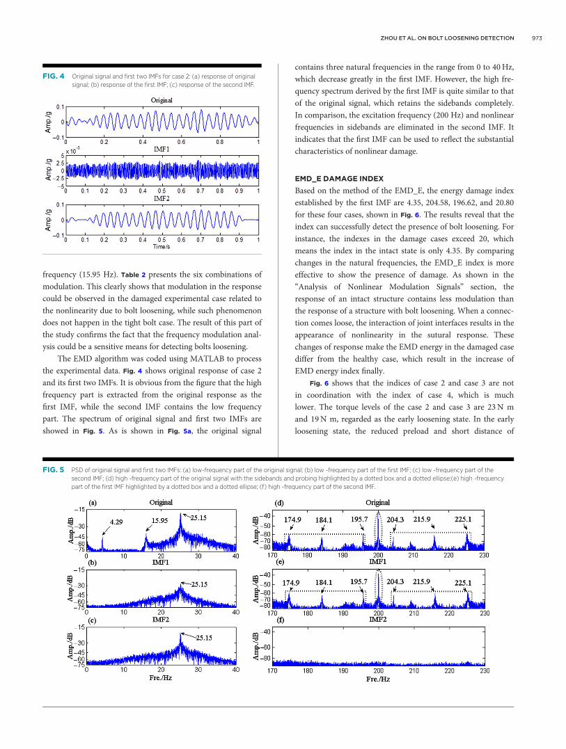
showed in Fig. 5. As is shown in Fig. 5a, the original signal
contains three natural frequencies in the range from 0 to 40Hz,
which decrease greatly in the first IMF. However, the high fre-
quency spectrum derived by the first IMF is quite similar to that
of the original signal, which retains the sidebands completely.
In comparison, the excitation frequency (200 Hz) and nonlinear
frequencies in sidebands are eliminated in the second IMF. It
indicates that the first IMF can be used to reflect the substantial
characteristics of nonlinear damage.
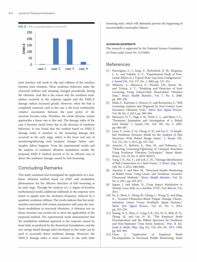
EMD_E DAMAGE INDEX
Based on the method of the EMD_E, the energy damage index
established by the first IMF are 4.35, 204.58, 196.62, and 20.80
for these four cases, shown in Fig. 6. The results reveal that the
index can successfully detect the presence of bolt loosening. For
instance, the indexes in the damage cases exceed 20, which
means the index in the intact state is only 4.35. By comparing
changes in the natural frequencies, the EMD_E index is more
effective to show the presence of damage. As shown in the
“Analysis of Nonlinear Modulation Signals” section, the
response of an intact structure contains less modulation than
the response of a structure with bolt loosening. When a connec-
tion comes loose, the interaction of joint interfaces results in the
appearance of nonlinearity in the sutural response. These
changes of response make the EMD energy in the damaged case
differ from the healthy case, which result in the increase of
EMD energy index finally.
Fig. 6 shows that the indices of case 2 and case 3 are not
in coordination with the index of case 4, which is much
lower. The torque levels of the case 2 and case 3 are 23N m
and 19N m, regarded as the early loosening state. In the early
loosening state, the reduced preload and short distance of
FIG. 4 Original signal and first two IMFs for case 2: (a) response of original
signal; (b) response of the first IMF; (c) response of the second IMF.
FIG. 5 PSD of original signal and first two IMFs: (a) low-frequency part of the original signal; (b) low -frequency part of the first IMF; (c) low -frequency part of the
second IMF; (d) high -frequency part of the original signal with the sidebands and probing highlighted by a dotted box and a dotted ellipse;(e) high -frequency
part of the first IMF highlighted by a dotted box and a dotted ellipse; (f) high -frequency part of the second IMF.
ZHOU ET AL. ON BOLT LOOSENING DETECTION 973
joint interface will result in slip and collision of the interface
between joint elements. These nonlinear behaviors make the
structural stiffness and damping changed periodically during
the vibration. And this is the reason why the nonlinear mod-
ulation occurred in the response signals and the EMD_E
damage indices increased greatly. However, when the bolt is
completely removed, such as the case 4, the local nonlinearity
(relative movements between the joint parts) of the
structure become weak. Therefore, the whole dynamic system
approaches a linear one at this end. The damage index of the
case 4 becomes much lower due to the decrease of nonlinear
behaviors. It was found that the method based on EMD_E
damage index is sensitive to the loosening damage that
occurred in the early stage, which is the focus and aim of
monitoring/detecting such incipient changes before cata-
strophic failure happens. From the experimental results and
the analysis of nonlinear vibration modulation model, the
proposed EMD_E method proved to be an efficient way to
detect the nonlinear damage caused by bolt loosening.
Concluding Remarks
This study examined and investigated the application of a non-
linear vibration method based on EMD and modulation
phenomenon for the effective detection of bolt loosening at
its early stage. Through the analyses of a 2 degree-of-freedom
mathematical model, additional sidebands in the response were
found to appear near the excitation frequency, induced by a
quadratic nonlinear stiffness. The results indicate that the nonli-
nearities associated with system parameters will cause the non-
linear modulation in structural vibrations. A vibration test on
frame structure was carried out to show the applicability of the
proposed method. The experimental result demonstrated that
the modulation sideband appeared in the response caused by
loose bolts as predicted by the theoretical formulations, and the
new energy-based damage index developed in this study can be
used to accurately detect nonlinear damage. Moreover, the
EMD_E damage index is more sensitive to the early bolts
loosening state, which will ultimately prevent the happening of
uncontrollable catastrophic failures.
ACKNOWLEDGMENTS
The research is supported by the National Science Foundation
of China under Grant No. 51378402.
References
[1] Hartwigsen, C. J., Song, Y., McFarland, D. M., Bergman,L. A., and Vakakis, A. F., “Experimental Study of Non-Linear Effects in a Typical Shear Lap Joint Configuration,”J. Sound Vib., Vol. 277, No. 1, 2004, pp. 327–351.
[2] Milanese, A., Marzocca, P., Nichols, J.M., Seaver, M.,and Trickey, S. T., “Modeling and Detection of JointLoosening Using Output-Only Broad-Band VibrationData,” Struct. Health Monitor., Vol. 7, No. 4, 2008,pp. 309–328.
[3] Huda, F., Kajiwara, I., Hosoya, N., and Kawamura, S., “BoltLoosening Analysis and Diagnosis by Non-Contact LaserExcitation Vibration Tests,” Mech. Syst. Signal Process.,Vol. 40, No. 2, 2013, pp. 589–604.
[4] Shiryayev, O. V., Page, S. M., Pettit, C. L., and Slater, J. C.,“Parameter Estimation and Investigation of a BoltedJoint Model,” J. Sound Vib., Vol. 307, No. 3, 2007,pp. 680–697.
[5] Luan, Y., Guan, Z. Q., Cheng, G. D., and Liu, S., “A Simpli-fied Nonlinear Dynamic Model for the Analysis of PipeStructures With Bolted Flange Joints,” J. Sound Vib.,Vol. 331, No. 2, 2012, pp. 325–344.
[6] Amerini, F., Barbieri, E., Meo, M., and Polimeno, U.,“Detecting Loosening/Tightening of Clamped StructuresUsing Nonlinear Vibration Techniques,” Smart Mater.Struct., Vol. 19, No. 8, 2010, 085013.
[7] Yang, J. N., Xia, Y., and Loh, C. H., “Damage Identificationof Bolt Connections in a Steel Frame,” J. Struct. Eng., Vol.140, No. 3, 2013, 04013064.
[8] Amerini, F. and Meo, M., “Structural Health Monitoringof Bolted Joints Using Linear and Nonlinear Acoustic/Ultrasound Methods,” Struct. Health Monitor., Vol. 10,No. 6, 2011, pp. 659–672.
[9] Jaques, J. and Adam, D., Using Impact Modulation toIdentify Loose Bolts on a Satellite, DTIC, Fort Belvoir, VA,2011.
[10] Su, Z., Zhou, C., Hong, M., Cheng, L., Wang, Q., and Qing,X., “Acousto-Ultrasonics-Based Fatigue Damage Charac-terization: Linear Versus Nonlinear Signal Features,”Mech. Syst. Signal Process., Vol. 45, No. 1, 2014,pp. 225–239.
[11] Huang, N. E., Shen, Z., Long, S. R., Wu, M. X., Shih, H. H.,Zheng, Q., and Liu, H. H., “The Empirical ModeDecomposition and the Hilbert Spectrum for Nonlinearand Non-Stationary Time Series Analysis,” Proc. R. Soc.Lond A: Math., Phys. Eng. Sci., Vol. 454, No. 1971, 1998,pp. 903–995.
[12] Chen, J., “Application of Empirical ModeDecomposition in Structural Health Monitoring: Some
FIG. 6 EMD_E evaluated based on the first IMF.
Journal of Testing and Evaluation974

Experience,” Adv. Adapt. Data Anal., Vol. 1, No. 4, 2009,pp. 601–621.
[13] Loutridis, S. J., “Damage Detection in Gear Systems UsingEmpirical Mode Decomposition,” Eng. Struct., Vol. 26,No. 12, 2004, pp. 1833–1841.
[14] Cheraghi, N. and Taheri, F., “A Damage Index for Struc-tural Health Monitoring Based on the Empirical ModeDecomposition,” J. Mech. Mater. Struct., Vol. 2, No. 1,2007, pp. 43–61.
[15] Esmaeel, R. A. and Taheri, F., “Application of a Simple andCost-Effective Method for Detection of Bolt Self-
Loosening in Single Lap Joints,” Nondestruct. Test. Eval.,Vol. 28, No. 3, 2013, pp. 208–225.
[16] Razi, P., Esmaeel, R. A., and Taheri, F., “Application of aRobust Vibration-Based Non-Destructive Method forDetection of Fatigue Cracks in Structures,” Smart Mater.Struct., Vol. 20, No. 11, 2011, 115017.
[17] Bograd, S., Reuss, P., Schmidt, A., Gaul, L., and Mayer, M.,“Modeling the Dynamics of Mechanical Joints,” Mech.Syst. Signal Process., Vol. 25, No. 8, 2011, pp. 2801–2826.
[18] Nayfeh, A. H. and Mook, D. T., Nonlinear Oscillations,John Wiley & Sons, New York, 1979.
ZHOU ET AL. ON BOLT LOOSENING DETECTION 975