application of nano-cutting for mechanical characterization of materials
TRANSCRIPT

Materials Letters 63 (2009) 2257–2259
Contents lists available at ScienceDirect
Materials Letters
j ourna l homepage: www.e lsev ie r.com/ locate /mat le t
Application of nano-cutting for mechanical characterization of materials
Fuminori Saito a,⁎, Itsuo Nishiyama b, Toshio Hyodo a
a Graduate School of Arts and Sciences, The University of Tokyo, 3-8-1 Komaba, Meguro, Tokyo 153-8902, Japanb Daipla Wintes Co. Ltd., 1-3-26 Nagasunishidori, Amagasaki, 660-0807, Japan
⁎ Corresponding author. Tel.: +81 3 5454 6830; fax:E-mail address: [email protected] (F.
0167-577X/$ – see front matter © 2009 Elsevier B.V. Adoi:10.1016/j.matlet.2009.07.037
a b s t r a c t
a r t i c l e i n f oArticle history:Received 11 June 2009Accepted 21 July 2009Available online 28 July 2009
Keywords:Characterization methodsMechanical propertiesThin filmsThick films
A novel technique for the mechanical characterization of materials near the surface using a nano-cuttingprocess is proposed. In this technique a cutting machine cuts a layer of the specimen material, and thestresses on the shear plane and the shear angle deduced from the measured components of the cutting forceare used for the characterization. The usefulness of this method is demonstrated by a cutting of poly methyl-methacrylate (PMMA) surface with a nano-cutting machine SAICAS.
© 2009 Elsevier B.V. All rights reserved.
1. Introduction
Reliable measurement of the characterization of the surfaces andfilms is important for the estimation of the durability of a wide rangeof industrial products. The techniques employed in the investigationof mechanical properties of materials include the nano- and micro-indentation method [1,2] and the scratch method [3]. A recently devel-oped nano-cutting machine, SAICAS (Surface and Interfacial CuttingAnalysis System) [4,5], has great potential for use in the characterizationof the mechanical properties of surfaces and films. Cutting using theSAICAS is essentially the same as typical metal cutting, though its ap-plication is not restricted to metallic specimens.
In the present work, we propose a new method for the charac-terization of the mechanical properties of materials in terms of thestresses and the shear angle, and demonstrate its validity by an ex-periment employing the SAICAS.
2. Theory
One of the mode of cuttings we use in the analysis is the orthog-onal cutting (two dimensional cutting) [6] as shown in Fig. 1, wherethe depth of cut is constant and the cutting edge is a straight lineperpendicular to the direction of the relative motion between theedge and the specimen. For the sake of simplicity we here use theshear plain model [6,7] of the orthogonal cutting originally developedfor the macroscopic metal cutting. Actual metal cutting process ismuch more complicated than this model describes. A lot of efforts
+81 3 5454 6542.Saito).
ll rights reserved.
have been made to improve the model, taking into account the ex-tended deformation zone, very high deformation rate, and the effectof the increase in temperature. For recent examples, see [8–11].Although nano-cutting characterization of the mechanical propertiesof materials shares some of the complications in common with themacroscopic metal cutting, we assume that the former is more plau-sibly described by the shear plain model than the latter, since cuttingspeed is about nine orders of magnitude smaller.
Another mode of cutting used for the analysis in this work is acutting in which the tool advances inclined at an angle ψN0, as shownin Fig. 2. In this type of cutting process, the depth of cut is not constantbut increases as the cutting tool advances. We shall call this “slantedorthogonal cutting” and the traditional orthogonal cutting “parallelorthogonal cutting”. Slanted orthogonal cutting is found in manyinstances, especially at the beginning of a cutting by a tool with astraight edge. Lines AB in Figs. 1 and 2 are the sections of the shearplanes which separate the chips and the specimens. The angle, ϕ,between the shear plane and the surface is called the shear angle. Forparallel orthogonal cutting, the angle between the shear plane and themachined surface is also ϕ, whilst for slanted orthogonal cutting, thecorresponding angle is ϕ+ψ.
First we show that a shear plane model [6,7] can be applied to theslanted orthogonal cuttingwith only small modification. In the cuttingprocesses shown in Figs. 1 and 2, the cutting tool exerts a force R onthe chip, whilst the specimen exerts a force R′ on the chip. Forequilibrium, R and R′ are equal in magnitude and opposite in direc-tion. The force R may be resolved in relation to the shear plane intothe shearing force Fs, and the compressive force Fn. It may also beresolved into a component Fh parallel to the surface of the specimenand a component perpendicular to the surface Fv.
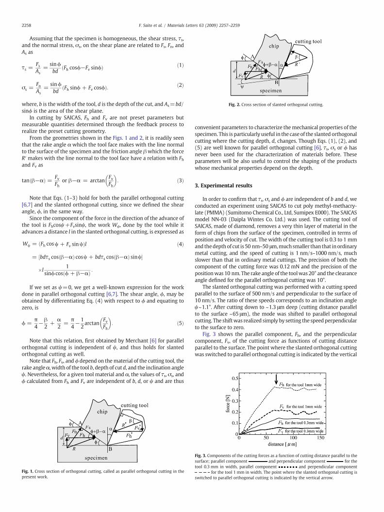
Fig. 2. Cross section of slanted orthogonal cutting.
2258 F. Saito et al. / Materials Letters 63 (2009) 2257–2259
Assuming that the specimen is homogeneous, the shear stress, τs,and the normal stress, σs, on the shear plane are related to Fs, Fn, andAs as
τs =FsAs
=sinϕbd
ðFh cosϕ−Fv sinϕÞ ð1Þ
σs =FnAs
=sinϕbd
ðFh sinϕ + Fv cosϕÞ: ð2Þ
where, b is the width of the tool, d is the depth of the cut, and As=bd/sinϕ is the area of the shear plane.
In cutting by SAICAS, Fh and Fv are not preset parameters butmeasurable quantities determined through the feedback process torealize the preset cutting geometry.
From the geometries shown in the Figs. 1 and 2, it is readily seenthat the rake angle α which the tool face makes with the line normalto the surface of the specimen and the friction angle βwhich the forceR′ makes with the line normal to the tool face have a relation with Fhand Fv as
tanðβ−αÞ = FvFh
or β−α = arctanFvFh
� �: ð3Þ
Note that Eqs. (1–3) hold for both the parallel orthogonal cutting[6,7] and the slanted orthogonal cutting, since we defined the shearangle, ϕ, in the same way.
Since the component of the force in the direction of the advance ofthe tool is Fhcosψ+Fvsinψ, the work Wψ, done by the tool while itadvances a distance l in the slanted orthogonal cutting, is expressed as
Wψ = ðFh cosψ + Fv sinψÞl
= ½bdτs cosðβ−αÞ cosψ + bdτs cosðβ−αÞ sinψ�
�l1
sinϕ cosðϕ + β−αÞ :
ð4Þ
If we set as ψ=0, we get a well-known expression for the workdone in parallel orthogonal cutting [6,7]. The shear angle, ϕ, may beobtained by differentiating Eq. (4) with respect to ϕ and equating tozero, is
ϕ =π4−β
2+
α2
=π4−1
2arctan
FvFh
� �: ð5Þ
Note that this relation, first obtained by Merchant [6] for parallelorthogonal cutting is independent of ψ, and thus holds for slantedorthogonal cutting as well.
Note that Fh, Fv, andϕ depend on thematerial of the cutting tool, therake angleα, width of the tool b, depth of cut d, and the inclination angleψ. Nevertheless, for a given tool material and α, the values of τs, σs, andϕ calculated from Fh and Fv are independent of b, d, or ψ and are thus
Fig. 1. Cross section of orthogonal cutting, called as parallel orthogonal cutting in thepresent work.
convenient parameters to characterize themechanical properties of thespecimen. This is particularly useful in the case of the slanted orthogonalcutting where the cutting depth, d, changes. Though Eqs. (1), (2), and(5) are well known for parallel orthogonal cutting [6], τs, σs or ϕ hasnever been used for the characterization of materials before. Theseparameters will be also useful to control the shaping of the productswhose mechanical properties depend on the depth.
3. Experimental results
In order to confirm that τs, σs and ϕ are independent of b and d, weconducted an experiment using SAICAS to cut poly methyl-methacry-late (PMMA) (Sumitomo Chemical Co., Ltd, Sumipex E000). The SAICASmodel NN-03 (Daipla Wintes Co. Ltd.) was used. The cutting tool ofSAICAS, made of diamond, removes a very thin layer of material in theform of chips from the surface of the specimen, controlled in terms ofposition and velocity of cut. Thewidth of the cutting tool is 0.3 to 1 mmand thedepthof cut is 50 nm–50 μm,muchsmaller than that inordinarymetal cutting, and the speed of cutting is 1 nm/s–1000 nm/s, muchslower than that in ordinary metal cuttings. The precision of both thecomponent of the cutting force was 0.12 mN and the precision of thepositionwas 10 nm. The rake angle of the toolwas 20° and the clearanceangle defined for the parallel orthogonal cutting was 10°.
The slanted orthogonal cutting was performed with a cutting speedparallel to the surface of 500 nm/s and perpendicular to the surface of10 nm/s. The ratio of these speeds corresponds to an inclination angleψ~1.1°. After cutting down to ~1.3 μm deep (cutting distance parallelto the surface ~65 μm), the mode was shifted to parallel orthogonalcutting. The shiftwas realized simply by setting the speedperpendicularto the surface to zero.
Fig. 3 shows the parallel component, Fh, and the perpendicularcomponent, Fv, of the cutting force as functions of cutting distanceparallel to the surface. The point where the slanted orthogonal cuttingwas switched to parallel orthogonal cutting is indicated by the vertical
Fig. 3. Components of the cutting forces as a function of cutting distance parallel to thesurface; parallel component and perpendicular component for thetool 0.3 mm in width, parallel component and perpendicular component
for the tool 1 mm in width. The point where the slanted orthogonal cutting isswitched to parallel orthogonal cutting is indicated by the vertical arrow.
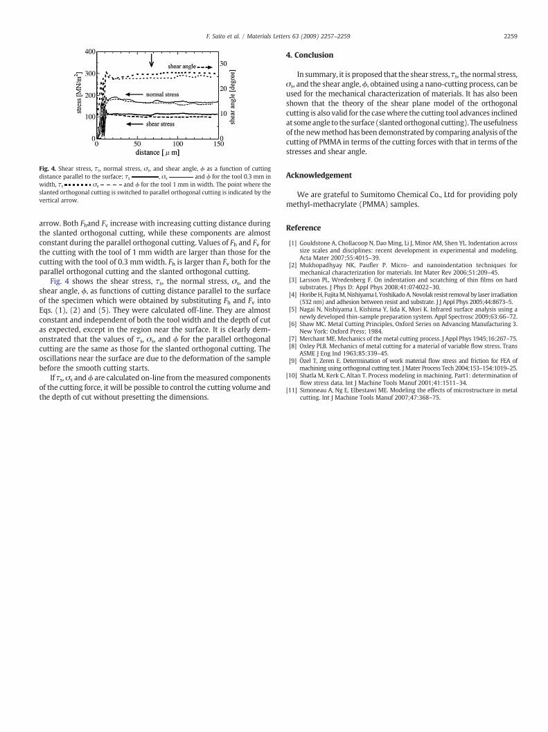
Fig. 4. Shear stress, τs, normal stress, σs, and shear angle, ϕ as a function of cuttingdistance parallel to the surface; τs , σs and ϕ for the tool 0.3 mm inwidth, τs σs and ϕ for the tool 1 mm in width. The point where theslanted orthogonal cutting is switched to parallel orthogonal cutting is indicated by thevertical arrow.
2259F. Saito et al. / Materials Letters 63 (2009) 2257–2259
arrow. Both Fhand Fv increase with increasing cutting distance duringthe slanted orthogonal cutting, while these components are almostconstant during the parallel orthogonal cutting. Values of Fh and Fv forthe cutting with the tool of 1 mm width are larger than those for thecutting with the tool of 0.3 mmwidth. Fh is larger than Fv both for theparallel orthogonal cutting and the slanted orthogonal cutting.
Fig. 4 shows the shear stress, τs, the normal stress, σs, and theshear angle, ϕ, as functions of cutting distance parallel to the surfaceof the specimen which were obtained by substituting Fh and Fv intoEqs. (1), (2) and (5). They were calculated off-line. They are almostconstant and independent of both the tool width and the depth of cutas expected, except in the region near the surface. It is clearly dem-onstrated that the values of τs, σs, and ϕ for the parallel orthogonalcutting are the same as those for the slanted orthogonal cutting. Theoscillations near the surface are due to the deformation of the samplebefore the smooth cutting starts.
If τs, σs and ϕ are calculated on-line from themeasured componentsof the cutting force, it will be possible to control the cutting volume andthe depth of cut without presetting the dimensions.
4. Conclusion
In summary, it is proposed that the shear stress, τs, the normal stress,σs, and the shear angle,ϕ, obtained using a nano-cutting process, can beused for the mechanical characterization of materials. It has also beenshown that the theory of the shear plane model of the orthogonalcutting is also valid for the casewhere the cutting tool advances inclinedat someangle to the surface (slantedorthogonal cutting). Theusefulnessof the newmethod has been demonstrated by comparing analysis of thecutting of PMMA in terms of the cutting forces with that in terms of thestresses and shear angle.
Acknowledgement
We are grateful to Sumitomo Chemical Co., Ltd for providing polymethyl-methacrylate (PMMA) samples.
Reference
[1] Gouldstone A, Chollacoop N, Dao Ming, Li J, Minor AM, Shen YL. Indentation acrosssize scales and disciplines: recent development in experimental and modeling.Acta Mater 2007;55:4015–39.
[2] Mukhopadhyay NK, Paufler P. Micro- and nanoindentation techniques formechanical characterization for materials. Int Mater Rev 2006;51:209–45.
[3] Larsson PL, Wredenberg F. On indentation and scratching of thin films on hardsubstrates. J Phys D: Appl Phys 2008;41:074022–30.
[4] HoribeH, FujitaM,Nishiyama I, YoshikadoA.Novolak resist removal by laser irradiation(532 nm) and adhesion between resist and substrate. J J Appl Phys 2005;44:8673–5.
[5] Nagai N, Nishiyama I, Kishima Y, Iida K, Mori K. Infrared surface analysis using anewly developed thin-sample preparation system. Appl Spectrosc 2009;63:66–72.
[6] Shaw MC. Metal Cutting Principles, Oxford Series on Advancing Manufacturing 3.New York: Oxford Press; 1984.
[7] Merchant ME. Mechanics of the metal cutting process. J Appl Phys 1945;16:267–75.[8] Oxley PLB. Mechanics of metal cutting for a material of variable flow stress. Trans
ASME J Eng Ind 1963;85:339–45.[9] Özel T, Zeren E. Determination of work material flow stress and friction for FEA of
machining using orthogonal cutting test. J Mater Process Tech 2004;153–154:1019–25.[10] Shatla M, Kerk C, Altan T. Process modeling in machining. Part1: determination of
flow stress data. Int J Machine Tools Manuf 2001;41:1511–34.[11] Simoneau A, Ng E, Elbestawi ME. Modeling the effects of microstructure in metal
cutting. Int J Machine Tools Manuf 2007;47:368–75.