application of hydrology enhanced flow direction grids within arc hydro frank kenny and bryce...
TRANSCRIPT

Application of Hydrology Enhanced Flow Direction Grids Within Arc Hydro
Frank Kenny and Bryce MatthewsOntario Ministry of Natural Resources
Peterborough, Ontario, [email protected] and [email protected]
Remote Sensing Across the Great Lakes: Observations, Monitoring and Action
April 4-6th, 2006

ONTARIO, CANADA
Peterborough

Presentation Overview
• Provincial Watershed Project – where we are in Ontario/where we are going
• Commonly encountered problems in raster hydrology
• Strategies for optimizing the Raster environment for hydrology
• Developing “Enhanced” flow direction grids
• Application Example – Accommodating Tile Drain fields with “Enhanced” flow direction grids.

Where we are in OntarioSeamless Covers
Hydrology Network - The Arc Hydro “Backbone”
Provincial Digital Elevation Model
• Over 10,000, 1:10/20 K scale Photogrammetrically derived topographic maps have been seamlessly merged.
• Network Geometry has been developed for the province (to approx.. 52 deg)• Every Ontario stream QA/QC by local Conservation Authorities and MNR district.
• Version I completed (2000) – Utilizing ANUDEM• Version II just completed (2006) – Includes the integration of lake elevation and DTM data.
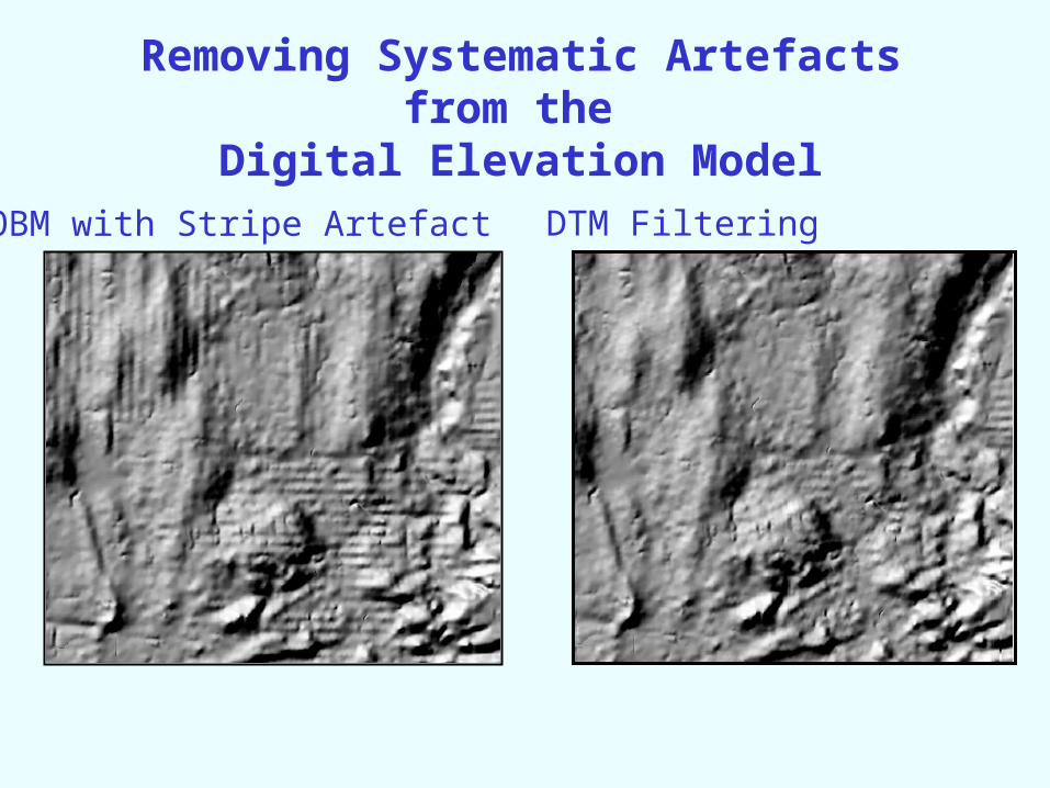
Removing Systematic Artefacts from the Digital Elevation Model
OBM with Stripe Artefact DTM Filtering
Arc Hydro
Provincial Flow Direction Grid
• 3 major rounds of Training Completed – Dr. Dean Djokic • Implementation in seven major northern Ontario Watersheds.• Being adopted across 30 southern Ontario Watershed Based Conservation Authorities
• Methodology refined and finished • Developed and loaded into the Land Information Ontario Warehouse
Where we are at (part II)
Commonly Encountered Problems in Raster Hydrology
• Application of a uniform “cutoff” value to accurately reflect known hydrology.
• Limitations of the DEM source data to accurately depict hydrology patterns.

100 Pixel Flow Accumulation Overlain the 1:50K Hydrology
Notice alignment is generally good - although one major watershed error is evident (denoted )

STREAMLINE FUNCTION AT VARIOUS FLOW ACCUMULATION CUT-OFFS
1:50K NTS HYDROLOGY 200 PIXEL DRAINAGE
100 PIXEL DRAINAGE 50 PIXEL DRAINAGE

Strategies for Optimizing the Raster Environment for Hydrology
1. Inclusion of a flow directed hydrology network as a boundary condition during DEM interpolation. To encode known flow directions in decreasing elevations. (e.g. ANUDEM, TOPOGRID).
2. DEM modifications, post creation using a drainage network to ensure focused flow along and down known water courses. (eg. Stream Burning, AGREE)
3. Redeveloping the Flow Direction Grid to include the Topological information Content of the hydrology network and water bodies. (The proposed method – this Presentation)

Steps to Developing an “Enhanced” Flow Direction Grid
Three Primary Inputs
1. Standard Approach to deriving flow directions (eg. FLOWDIRECTION)
2. A hybridized raster/vector topological analysis to assigning D8 flow directions to cells that intersect the network.
3. An iterative raster single cell dilation
and D8 assignment from within water bodies to focus flow towards the virtual segments.
4. A merging of results from steps 1, 2 and 3 to produce a final “enhanced flow direction grid”.

Catchment, DrainagePoint and DrainageLine
The Catchment, DrainagePoint and DrainageLine feature classes in Arc Hydro store the vector products resulting from terrain analysis using a Digital Elevation Model.
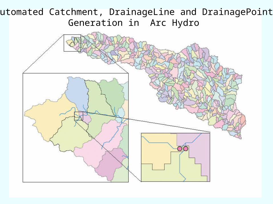
Automated Catchment, DrainageLine and DrainagePoint Generation in Arc Hydro

Scales of representation of Drainage Systems
Basins – drainage areas for water resources management
Catchments – subdivision of Basin into elementary drainage areas by physical rules
Digital Elevation Model – land surface terrain grid cells
Watersheds – subdivision of Basinfor a particular hydrologic purpose

Arc Hydro Drainage (raster) and Arc Hydro Hydrography (vector)
(continued)
This is actually two separate problems appearing as one…
1) Gross alignment errors between the raster flow direction grid and the vector photogrammetrically interpreted hydrography
2) A DrainageLine density issue associated with applying a uniform flow accumulation cut-off value.
Within WRIP we believe we have in a very efficient manner solved both.

A)
C) D)
B)100 m.
Example of a Junction within a Wetland TIN to Grid ANUDEM
Stream Burning Enhanced Flow Direction

A)
D)C)
B)100 m.
Example of On-Network Lakes and Stream Junctions within a Wetland
TIN to Grid ANUDEM
Stream Burning Enhanced Flow Direction

A)
C) D)
B)100 m.
1
2
A Single Meandering Stream TIN to Grid ANUDEM
Steam Burning Enhanced Flow Direction
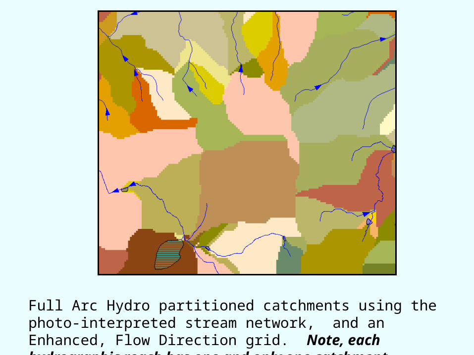
Full Arc Hydro partitioned catchments using the photo-interpreted stream network, and an Enhanced, Flow Direction grid. Note, each hydrographic reach has one and only one catchment.

Natural Drainage
Stream Network
Anthropogenic Boundary
Anthropogenic “Pipes”
Relative Time of Travel
0 - 600
600 - 1,200
1,200 - 1,800
1,800 - 12,483
Minutes
to Water Features
Accommodating Tile Drain Fields with “Enhanced” Flow Direction Grids.


Hydro Networks
“The hydro network is the backbone of Arc Hydro, created from edges and junctions. The topological connection of its HydroEdges and HydroJunctions in a geometric network enables tracing of water movements upstream and through streams, rivers, and water bodies”
“ Relationships built from the HydroJunctions connect drainage areas and point features such as stream gage stations to the hydro network. Locations on the hydro network are defined by a river-addressing scheme that defines where points are located on lines within drainage areas, allowing measurements of flow distance between any two points on a flow path.”

Scales of representation of Drainage Systems
Basins – drainage areas for water resources management
Catchments – subdivision of Basin into elementary drainage areas by physical rules
Digital Elevation Model – land surface terrain grid cells
Watersheds – subdivision of Basinfor a particular hydrologic purpose