application of hts squids in nondestructive evaluation of
TRANSCRIPT

Application of HTS SQUIDs in Nondestructive Evaluation ofAircraft Parts and Concrete Bridges
Hans-Joachim Krause
Forschungszentrum Jülich, D-52425 Jülich, Germany
Abstract
The challenge for applications of HTS SQUID in non-destructive evaluation is thedevelopment of mobile SQUID systems operating in hostile environments. For eddy currentdetection of deep-lying flaws in aircraft wheels, an automated aircraft wheel inspectionsystem using a HTS SQUID magnetometer in conjunction with Joule-Thomson machinecooling was developed. The aircraft wheel testing is being performed with the wheel slowlyrotating and a robot with the SQUID enclosure scanning stepwise along the wheel axis. Asmall crack with an inside penetration of only 10% of the wall thickness was found byscanning the outside of the wheel. The results of a wheel measurement campaign at theLufthansa base at Frankfurt airport are presented.
Using SQUID eddy current testing, the detection of cracks at rivet joints and identifyingcorrosion damage hidden deeply in the tested structure has been shown. However, therequirement to take maps of the magnetic field, usually by meander-shaped scans, leads tounacceptably long measurement times. A solution is the development of SQUID arrays foreddy current fuselage testing. The multiplexed operation of three planar HTS rf SQUIDgradiometers with one readout electronics and one cable is shown, demonstrating theadvantage of lower liquid nitrogen boil-off.
For detection of tendon ruptures in prestressed members of bridges, a multi-channel SQUIDsystem was developed. The tendons are magnetized by scanning a yoke magnet along theconcrete surface. Four HTS dc-SQUID magnetometers with ramp-type junctions optimizedfor high-field performance are used to record the magnetic stray field. Signals from stirrups ofthe mild steel reinforcement are suppressed by means of a sophisticated signal analysis.Subsequent correlation analysis with the dipolar signal of a typical void yields rupture signalamplitudes. Results of measurements on a German highway bridge are presented. Ruptureindications were verified as originating from broken strands by opening the bridge deck.
1. IntroductionSuperconducting Quantum Interference Devices (SQUIDs) are the magnetic field sensorswith the best field sensitivity and the largest dynamic range known to date. Following thedevelopment of SQUID sensors, many research groups worldwide have shown the use ofSQUIDs in conjunction with electromagnetic Non-destructive Evaluation (NDE), see forexample the review of Jenks et al. [1]. In this paper, we’ll present two examples of prototypedevelopment conducted in the framework of joint German R&D projects with industry.
The first potential application field for SQUID NDE is aircraft testing. Aircraft, beingexposed to strong forces, moisture and changing temperatures, have to be checked regularlyfor cracks and corrosion in order to assure for flight safety. Eddy-current testing by inductivesensors is a common NDT method in aircraft maintenance. Compared to induction coils,SQUID systems offer a higher sensitivity at low excitation frequencies, permitting thedetection of deeper flaws, and an excellent linearity, allowing quantitative evaluation ofmagnetic field maps from the investigated structure [2,3]. The potential of eddy currenttesting with HTS SQUIDs has previously been demonstrated for up to 5 cm deep-lying

defects in stacks of aluminum sheets using a stationary rf SQUID gradiometer [4]. Using asample from aircraft aluminum alloy, with a saw cut hidden deep in the material, it wasshown that a HTS SQUID magnetometer system yields an improvement in signal-to-noiseratio by more than two orders of magnitude, compared to a conventional eddy current system[5]. For practical applications, the SQUID systems have to be made mobile and capable tooperate without any magnetic shielding in maintenance hangars where the level of electro-magnetic disturbances is very high [6,7]. In a joint R&D project, Rohmann GmbH, DASA,Lufthansa Technik AG, ILK Dresden, University of Giessen (Institute for Applied Physics)and Research Centre Jülich are trying to introduce HTS SQUIDs into aircraft maintenance.Project goal is the development of prototype SQUID systems that demonstrate of theadvantages of the new technique for aircraft wheel testing or fuselage testing.
The second application field is the inspection of concrete bridges containing prestressed steel[8]. The Federal road network of Germany contains about 13,000 prestressed concretebridges. Due to constantly growing volumes of traffic and higher loads per axle, thesestructures are subject to increasing loads. Regular inspections of all engineering structuresconsist mainly of a visual inspection, thus deterioration and damages are typically identifiedrather late. Non-destructive test methods (NDT) may provide a relatively quick andinexpensive means to establish whether a bridge is still in a serviceable condition. Particularlyimportant is the non-destructive identification of the position of defects in prestressedconcrete bridges, as the stability of the entire structure may be affected.
2. Testing of Aircraft parts with Eddy current and SQUID
2.1. The Eddy current techniqueNonmagnetic metallic materials are usually tested by an ac technique. Using alternatingcurrents has two significant advantages: first, the coupling of excitation to the material undertest can be done inductively, thus eliminating the need for impractical electrical contacts.Second, a narrowband lock-in readout scheme can be used, resulting in noise suppression. Inaddition, the quadrature component containing information on excitation energy dissipationcan be evaluated. Eddy current testing using a SQUID sensor is of special value in a highlysafety-relevant area such as aircraft testing, where small deep flaws need to be localized andsized in aluminum structures [9]. The first demonstration of aircraft lap joint testing wasperformed in shielding using a LTS SQUID system [10]. Subsequently, a cryocooled LTSsystem with remote differential sensing coils was used to demonstrate the detection of verysmall, hidden flaws without shielding [11]. With the advent of HTS SQUID gradiometers forunshielded operation, appropriate excitation-detection schemes were developed [4].
2.2. SQUID system componentsFor portable SQUID operation, a planar gradiometer design is well suited. The rf double holegradiometer [12] was designed for operation integrated into a hand-held system duringmovement in strong ambient fields commonly found in aircraft maintenance facilities. Agradiometer with a baseline of 3.7 mm and a gradient-to-flux coefficient of 15 nT/(cm Φ0),with a surrounding shielding ring, is used. The gradient sensitivity of the gradiometer isapproximately 1 pT/(cm√Hz) at eddy current frequencies in the range from 110 Hz to 1 kHz.The rf SQUID readout electronics with a high slew rate allows fast scanning in stronggradient fields. This is of importance when scanning over ferromagnetic objects.
In order to do the testing directly at the aircraft, the SQUID has to be equipped with mobilecooling. A lightweight nitrogen cryostat [13], constructed by ILK Dresden for operation inany orientation, allows one a portable SQUID operation. The mobile head weighs less than2 kg and has an operation time of 12 hours. A distance of only 3 mm between SQUID and

sample may be achieved. For a routine, stationary maintenance application such as aircraftwheel testing, SQUID cooling only needing electricity is advantageous. A commercial Joule-Thomson cryocooler (APD Cryotiger®) was adapted for liquid-nitrogen-free, low-noiseSQUID cooling [14]. Flexible plastic gas lines allow one to position the cold head.
The eddy current excitation is applied by a differential coil. Printed multi-turn double-D coilswith a diameter of 25 mm were mounted on the SQUID dewar and operated with excitationcurrents of up to 200 mArms. Amplitude and phase of the eddy current response field areevaluated by a Stanford Research SR830 digital lock-in amplifier and recorded by acomputer. This eddy current scheme ensures a minimum primary field at the location of theSQUID gradiometer. However, it leads to a quadrupolar signature of a small flaw.
2.3. Aircraft wheel testingAircraft wheels are subject to enormous stress and heat during take-off and landing. Becauseof the concentration of mechanical and thermal stress, hidden cracks emanate typically on theinside of the wheel, next to the keys on which brake structures are fastened. The cracks arecovered by heat shields and therefore not easily accessible from the inside. Today, the wheelsare eddy-current tested from the outside with a circumferential scan measurement, after takingoff the tires. Deep flaws are detected with a low-frequency eddy current probe. However, thesensitivity is limited to large flaws: flaws with 40% wall penetration from the inside and oflength twice the wall thickness can be identified reliably. In order to safely detect smallhidden flaws, the wheel has to be disassembled and be tested manually from the inside, e.g.with ultrasonic equipment.
Figure 1. Setup for aircraft wheel testing with SQUID. The Joule-Thomson cold head with the SQUIDmounted on top of the finger is moved along the wheel contour by a robot while the wheel isrotating.
The prototype SQUID system for wheel testing consists of an automated test stand with thewheel slowly rotating and a robot with the SQUID enclosure scanning stepwise along thewheel axis, see Figure 1. While the wheel is rotating, the robot moves the cryostat along itsouter contour. Thus, a two-dimensional eddy current mapping of the outer wheel surface isperformed.
During a three-day measurement campaign, the system was operated at the Lufthansa wheeltesting facility at Frankfurt Airport. Figure 2 shows a sample measurement of an AirbusA300-600 wheel.

Figure 2. SQUID measurement of an Airbus A300-600 wheel (main landing gear). The measurement wasconducted at Frankfurt airport, using a planar gradiometer with double D excitation (180 Hz,130mA). The figure shows the unfiltered quadrature component of the lock-in signal. In addition tosignals from 6 holes, a quadrupolar crack signature is clearly visible, located next to one of the ninekeys (vertical stripes) at a height of 250 mm.
It was demonstrated that the SQUID system is capable of detecting inner flaws by automatedscanning and eddy-current mapping from the outside. The smallest flaw detected with theSQUID was a 10%-flaw [15] (meaning that total wall thickness is weakened by 10% at theflaw location).
2.4. Aircraft fuselage testingDue to temperature and moisture changes in conjunction with mechanical stress, cracks andcorrosion may develop in the fuselage, often located in hidden layers close to rivets. State ofthe art with conventional eddy current equipment is the detection of 4.5 mm long second layercracks adjacent to rivets, underneath 2.2 mm of aluminum. For testing rivet rows, a planarHTS SQUID gradiometer was mounted in an orientation-independent cryostat, equipped witha double-D excitation coil and affixed to a fuselage surface scanner, see Figure 3.
Figure 3. Aircraft fuselage testing using a mobile SQUID system with a x-y-scanner. The flexible scanner isaffixed to the fuselage with suction cups. The SQUID is scanned in a meander-like path, thusyielding an eddy-current map of the fuselage section under test.

Figure 4 shows a typical scan of a fuselage section. Using the planar gradiometer sensor andthe differential excitation coil, each rivet yields a quadrupolar signal as can clearly be seen inthe scan map. The rivet and the rivet hole give a strong signal even if there is no additionalfault like a crack. By software windowing of the impedance trace, the flaws are identified.The flaws can be located at the rivet, see map of the evaluated signal in Figure 4. Forcomparison, a conventional eddy current scan is also presented.
Figure 4. SQUID measurement of a calibration sample from DASA. The scan was performed with the planarSQUID gradiometer with multi-D excitation of 10 mA at 780 Hz. The scan area of 130 mm× 20 mm covers 5 rivets with 4 flaws, as sketched. They clearly show up in the evaluated scan.
However, the requirement to take maps of the magnetic field, usually by meander-shapedscans, leads to unacceptably long measurement times. Due to their inductive coupling to atank circuit, several rf SQUID sensors may be read out sequentially by selectively coupling totheir tank circuits, using only one electronics with a multiplexer [16]. A system withmultiplexed operation of three planar HTS rf SQUID gradiometers, operated with oneelectronics and one cable, is currently under development. The multiplexed SQUID sensorswere implemented in conjunction with an eddy current excitation and lock-in readout.Scanning is performed while continuously switching the operating SQUID, thus obtainingthree traces simultaneously [17].
3. Bridge inspection using the magnetic stray field technique and SQUID
The magnetic stray field measuring method is well suited for the inspection of prestressedsteel in concrete bridges [18,19,20,21]. The steel acts as a high permeability magnetic fieldguide. Cracks in the reinforcement bars are interruptions of that guide, thus giving rise to aleaking stray field. Typically, the flaw signal is hidden among signals of mild steelreinforcements (stirrups) located close to the concrete surface. Provided that the magneticfield sensors have sufficient sensitivity and linearity, flaw signals may be separated fromstructural disturbance signals by means of a specially developed signal analysis. A newlydeveloped system incorporating four SQUID sensors for the inspection of rebars in bridges ispresented [8]. The equipment has already been successfully used in field measurements.

3.1. Magnetic stray field techniqueThe principle of the magnetic stray field measurement technique is as follows: the tendonhidden in the concrete is magnetized using an exciting magnetic field Ho applied from theoutside of the concrete by means of a yoke magnet. This exciting field generates a magnetiza-tion in the reinforcement bars. Local disturbances of the distribution of this magnetization dueto ruptures or reductions of the cross section cause the emanation of a magnetic leakage flux(stray field) from the member. For the generation and the measurement of the stray field, aprobe containing the magnetization device (yoke magnet) and the sensors is moved along thedirection of the prestressed tendon outside the concrete surface (see Figure 5).
Stray Field
Yoke Magnet
xSensor
Applied Field H0
HS
Figure 5. The principle of magnetic leakage flux measurement.
The stray field measurement is either conducted during magnetization by the exciting field(active field) or as a residual field measurement. In the latter case, the stray field is caused bythe remanent magnetization of the steel after switching off the magnetization device. In theactive field measurement, ruptures of the longitudinal rebars appear as a local maximum. Ithas been shown that a single cracked rebar can be found in post-tensioned members, eventhough the magnetic signature of the crack is damped significantly due to the shielding effectof the surrounding flawless rebars and the jacket tube around the bars.
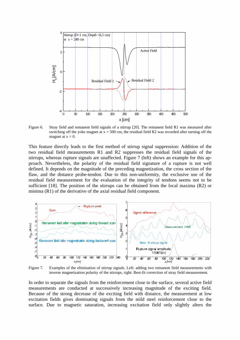
3.2. Signal analysisThe stray field signals are affected not only by ruptures of the tendon under consideration butalso by the stirrups close to the probe. Signal analysis methods for the suppression of signalsfrom the stirrups were developed [20,8]. The magnetic signature of a stirrup shows aconsiderably different shape in the active field, in comparison to the residual measurement.Due to the hysteresis behavior of the ferromagnetic material, the active field signal of a stirruphas an asymmetrical shape. The polarity of the antisymmetrical residual field measurementsignal of the stirrup depends on the location where the yoke magnet has been switched offduring the preceding magnetization of the member. A typical stray field and two residual fieldsignals of a single stirrup are shown in Figure 6. The residual field measurement R1 isperformed after the yoke magnet is switched off at the end of the measurement length. Incontrast, the measurement R2 denotes the case where the exciting field is switched off at thestarting position after a full magnetization scan. The residual field signature R2 of the stirrupis inverted compared to R1.
0 50 100 150 200 250 300 350 400 450 500-4
-2
0
2
4
Residual Field 1
Stirrup (D=1 cm, Depth =6,5 cm) at x = 248 cm
Residual Field 2
Active FieldH
x [A
/cm
]
x [cm]
Figure 6. Stray field and remanent field signals of a stirrup [20]. The remanent field R1 was measured afterswitching off the yoke magnet at x = 500 cm, the residual field R2 was recorded after turning off themagnet at x = 0.
This feature directly leads to the first method of stirrup signal suppression: Addition of thetwo residual field measurements R1 and R2 suppresses the residual field signals of thestirrups, whereas rupture signals are unaffected. Figure 7 (left) shows an example for this ap-proach. Nevertheless, the polarity of the residual field signature of a rupture is not welldefined. It depends on the magnitude of the preceding magnetization, the cross section of theflaw, and the distance probe-tendon. Due to this non-uniformity, the exclusive use of theresidual field measurement for the evaluation of the integrity of tendons seems not to besufficient [18]. The position of the stirrups can be obtained from the local maxima (R2) orminima (R1) of the derivative of the axial residual field component.
Figure 7. Examples of the elimination of stirrup signals. Left: adding two remanent field measurements withinverse magnetization polarity of the stirrups, right: Best-fit correction of stray field measurement.
In order to separate the signals from the reinforcement close to the surface, several active fieldmeasurements are conducted at successively increasing magnitude of the exciting field.Because of the strong decrease of the exciting field with distance, the measurement at lowexcitation fields gives dominating signals from the mild steel reinforcement close to thesurface. Due to magnetic saturation, increasing excitation field only slightly alters the

magnetization of the steel close to the surface. The signal increase at higher values of theexciting field Ho is mainly caused by the steel structures (rebars) deeper in the concrete.
The second technique for the elimination of the signals from the stirrups is direct subtractionof idealized signals. First, the exact position of the stirrups is calculated from a residual fieldsignal. Then, the signal portion of the stirrups is determined by means of the best fit methodwith regard to the signal of a single stirrup (Figure 6). Finally, the signal portion of thestirrups is subtracted from the measured signal. The essential portion of the signals of thetendon remains (Figure 7, right).
3.3. SQUID magnetometer sensorsFor this application, HTS dc SQUIDs which can be operated in strong magnetic fields weredeveloped [22], see Figure 8. The SQUIDs contain two YBCO/PBCO ramp-type Josephsonjunctions and a washer with slits. The field-to-flux coefficient was measured to be 600 nT/Φ0.When exposed to our maximum excitation fields (up to 15 mT), no degradation ofperformance was found. The observed increase in low frequency noise (Figure 1, right) is dueto 1/f noise of the current source driving the excitation magnet. For cooling the SQUID sensorarray, a mobile liquid nitrogen cryostat was developed. Since the SQUID is mounted on asapphire finger in the vacuum space of the cryostat, it can be operated orientation-independent. One refill of liquid nitrogen lasts for a working day.
Figure 8. Packaging, Layout and magnetic field resolution of the SQUID sensors used for rebar inspection.
3.4. Setup of the bridge inspection systemThe system consists of 4 SQUID magnetometers. They are mounted on sapphire fingersoriented radially in the liquid nitrogen cryostat. Thus, the SQUIDs measure the longitudinalfield component, in scanning direction. The cryostat is fixed in a yoke magnet on thetranslation stage. In order to check consistency with the previous measurement technique, 4Hall probes are also integrated with the system. A multi-channel readout and control elec-tronics, using digital signal processors for the SQUID flux-locked loop and signalpreprocessing [23], is used to acquire the data from the magnetic sensors and the positionencoder. Due to the implemented flux quanta counting, the digital SQUID electronicsachieves a dynamic range of 195 dB/√Hz with the high-field magnetometers. It is connectedto a computer via an optical link. Figure 9 shows schematically the setup of the system.

Figure 9. Schematic setup sketch of the SQUID system for magnetic inspection of rebars.
3.5. Measurements on a German highway bridgeAs an example for a field test of the system, we present results of SQUID measurement on thevalley bridge Michelsrombach (A7 near Fulda) [24,25]. At selected measurement positions,tendons were localized using the Ground Penetrating Radar (GPR) SPR-Scan from ERATechnology with a 1 GHz antenna. Subsequently, magnetic measurement scans wereperformed along the marked tendons, see Figure 10.
Figure 10. Schematic of the measurements conducted on the valley bridge Michelsrombach. First, the tendonswere localized using Ground Penetrating Radar (À). Subsequently, the prestressed steel rebars wereinspected by scanning the yoke with the SQUID system along the member (Á).
After Radar localization, magnetic measurement scans were performed along the tendons. Theinvestigation was carried out in scan segments of 260 cm length. At every location, nine scanswere conducted. After a recording of the pre-existing field, scans with increasing excitingfield were performed, followed by scans with decreasing field and subsequent remanent fieldscans after different premagnetization states. Before each measurement scan, the SQUID sen-sors were heated just above the critical temperature of the superconducting film in order to

eliminate trapped magnetic flux. The scan velocity was 0.1 m/s. Due to the SQUID heating,the total measurement time at one location was 20 min.
Figure 11 shows the correlation coefficient and the crack signal amplitude of the evaluatedstray field and remanent field scans at a selected location of the bridge.
Figure 11. Correlation coefficients and Rupture signal amplitudes.
Indication A at x = 45 cm yielded a correlation coefficient and a rupture signal amplitudebelow threshold. Opening of the concrete and the jacket tube protecting the rebars showedthat the indication emanated from a loose end of a rebar, see Figure 12 A. Indication B atx = 82±5 cm, however, gave an correlation coefficient and a rupture signal amplitude wellabove our threshold. The opening of the bridge deck (Figure 12 B) confirmed that two of theeight rebar wires were cracked at this location.
Figure 12. By opening the bridge deck, the indications A and B were confirmed as a loose end and a rupture.
4. Conclusions and outlook
For two selected aircraft NDE tasks, prototype SQUID systems were developed and tested inrealistic environments, demonstrating the practical usability of mobile HTS SQUID inconjunction with the eddy current technique. Equipped with orientation-independentcryogenics (position-independent miniature cryostat or Joule-Thomson machine-cooler) theHTS SQUID gradiometers worked successfully under electromagnetically noisy conditions.An automated test stand for SQUID testing of aircraft wheels, with the wheel slowly rotatingand a robot with the SQUID enclosure scanning stepwise along the wheel axis, detects deepcracks smaller than today’s limit of conventional eddy current devices. The system wassuccessfully tested in the Lufthansa wheel inspection facility at Frankfurt airport. Another

SQUID system has been successfully operated on a professional fuselage scanner. Withsubsequent signal processing, second layer cracks were detected adjacent to rivets.
The magnetic stray field technique is well suited to detect ruptures in prestressed steel tendonsof concrete bridges. A system utilizing HTS SQUID sensors with unsurpassed high fieldperformance and dynamic range was developed. Stray field as well as remanent field scans ofrebars after different premagnetization states were taken. Signals of the mild steelreinforcements (stirrups) were suppressed efficiently using a sophisticated signal analysisincluding best fit estimation of the stirrup signals, comparing residual field measurementsafter stirrup magnetization inversion, and crack signal correlation analysis. The applicabilityunder field conditions was demonstrated during bridge measurements. Magnetic indicationsof rebar cracks were verified by opening the bridge deck.
The upcoming challenge is to assist our industrial partners in further developing theprototypes and finally introducing them into the NDE market.
AcknowledgmentsThe work reviewed in this paper was jointly conducted by Institut für Schicht- und Ionen-technik, Institut für Festkörperforschung and Zentrallabor für Elektronik at Forschungs-zentrum Jülich, in conjunction with our industrial and research partners Rohmann GmbH,Frankenthal, Daimler-Chrysler Aerospace Airbus GmbH (DASA), Bremen, LufthansaTechnik AG, Frankfurt, ILK Dresden, University of Giessen (Institute for Applied Physics),Forschungs- und Materialprüfanstalt Baden-Württemberg, Stuttgart, Siempelkamp Prüf- undGutachtergesellschaft mbH, Dresden, and Bundesanstalt für Straßenwesen, Bergisch-Gladbach. Co-workers were M. Banzet, H. Bousack, A.I. Braginski, M.I. Faley, S. Gärtner,W. Glaas, M. Grüneklee, R. Hohmann, D. Lomparski, M. Maus, R. Otto, J. Schubert, W.Wolf, N. Wolters, Y. Zhang, and E. Zimmermann at Forschungszentrum, and K. Allweins, W.Becker, A. Binneberg, U. Gampe, C. Heiden, M. Junger, W.-B. Klemmt, M. v.Kreutzbruck, J.Krieger, R. Mattheus, M. Mück, G. Neudert, and G. Sawade at the partner institutions.Support by German BMBF under contracts No. 13N7249/2 and 13N7429/0 is gratefullyacknowledged.
This publication is based partly on the presentation made at the European ResearchConference (EURESCO) on "Future Perspectives of Superconducting Josephson Devices":Euroconference on Physics and Application of Multi-Junction Superconducting JosephsonDevices, Acquafredda di Maratea, Italy, 1-6 July 2000, organised by the European ScienceFoundation and supported by the European Commission, Research DG, Human PotentialProgramme, High-Level Scientific Conferences, Contract HPCFCT-1999-00135.
This information is the sole responsibility of the author and does not reflect the ESF orCommunity's opinion. The ESF and the Community are not responsible for any use that mightbe made of data appearing in this publication.
References[1] W.G. Jenks, S.S.H. Sadeghi, J.P. Wikswo, SQUIDs for Nondestructive Evaluation, Journal of Physics D
30, 293-323 (1997).
[2] G.B. Donaldson, A. Cochran, D. McA. McKirdy, The use of SQUIDs for Nondestructive Evaluation, in:SQUID Sensors: Fundamentals, fabrication and applications, NATO ASI series E, Vol. 329, Ed: H.Weinstock, Kluwer, Dordrecht, pp. 599-628 (1996).
[3] J.P. Wikswo, The magnetic inverse problem for NDE, in: SQUID Sensors: Fundamentals, fabrication andapplications, NATO ASI series E, Vol. 329, Ed: H. Weinstock, Kluwer, Dordrecht, pp. 629-695 (1996).

[4] Y. Tavrin, H.-J. Krause, W. Wolf, V. Glyantsev, J. Schubert, W. Zander, H. Bousack, Eddy currenttechnique with high temperature SQUID for nondestructive evaluation of nonmagnetic metallicstructures, Cryogenics 36, 83-86 (1996).
[5] M. v.Kreutzbruck, M. Mück, U. Baby, C. Heiden, Detection of deep lying cracks by eddy current SQUIDNDE, in: Proceedings of the 7th European Conference on Non-Destructive Testing, Ed: B. Larsen, 7th
ECNDT, Broendby, Denmark, pp. 46-52 (1998).
[6] H.-J. Krause, R. Hohmann, H. Soltner, D. Lomparski, M. Grüneklee, M. Banzet, J. Schubert, W. Zander,Y. Zhang, W. Wolf, H. Bousack, A. I. Braginski, M. L. Lucía, E. Zimmermann, G. Brandenburg, U.Clemens, H. Rongen, H. Halling, M. I. Faley, U. Poppe, H. Buschmann, G. Spörl, A. Binneberg, M.Junger, Mobile HTS SQUID System for Eddy Current Testing of Aircraft, in: Review of Progress inQuantitative Nondestructive Evaluation, Vol. 16, Eds: D.O. Thompson, D.E. Chimenti, Plenum, NewYork, pp. 1053-1060 (1997).
[7] R. Hohmann, H.-J. Krause, H. Soltner, M.I. Faley, Y. Zhang, D.F. He, C.A. Copetti, H. Bousack, C.Heiden, A.I. Braginski, HTS SQUID System with J-T-Cryocooler for Eddy Current NondestructiveEvaluation of Aircraft Structures, IEEE Trans. on Appl. Supercond. 7, 2860-2865 (1997).
[8] J. Krieger, H.-J. Krause, U. Gampe, G. Sawade, Magnetic field measurements on bridges and develop-ment of a mobile SQUID system, Proc. Intl. Conf. on NDE Techniques for Aging Infrastructure &Manufacturing, Newport Beach, California, USA, pp. 229-239 (1999).
[9] J.P. Wikswo, Y.P. Ma, N.G. Sepulveda, D.J. Staton, S. Tan, I.M. Thomas, I.M., SuperconductingMagnetometry: A possible technique for aircraft NDE, in: Nondestructive Testing of Aging Aircraft, Eds:M. T. Valley, N.K. Grande, A.S. Kobayashi, SPIE Proc., Vol. 2001, pp. 164-190 (1993).
[10] Y.P. Ma, J.P. Wikswo, Imaging subsurface defects using a SQUID magnetometer, in: Review of Progressin QNDE, Vol. 12, Eds: D.O. Thompson, D.E. Chimenti, Plenum Press, New York, pp. 1137-1143(1993).
[11] W.N. Podney, Eddy current evaluation of airframes using refrigerated SQUIDs, IEEE Trans. Appl.Supercond. 5, 2490-2492 (1995).
[12] Y. Zhang, H. Soltner, H.-J. Krause, E. Sodtke, W. Zander, J. Schubert, M. Grüneklee, D. Lomparski, M.Banzet, H. Bousack, A.I. Braginski, Planar HTS Gradiometers with Large Baseline, IEEE Trans. onAppl. Supercond. 7, 2866-2869 (1997).
[13] M.L. Lucía, R. Hohmann, M.I. Faley, H. Soltner, H.-J. Krause, G. Spörl, A. Binneberg, W. Wolf, H.Bousack, Operation of HTS SQUIDs with a Portable Cryostat: a SQUID System in Conjunction withEddy Current Technique for Non-Destructive Testing, IEEE Trans. on Appl. Supercond. 7, 2878-2881(1997).
[14] R. Hohmann, M. Maus, D. Lomparski, M. Grüneklee, Y. Zhang, H.-J. Krause, H. Bousack, A.I.Braginski, C. Heiden, Aircraft wheel testing wich machine-cooled HTS gradiometer system, IEEE Trans.on Appl. Supercond. 7, 3801-3804 (1997).
[15] R. Hohmann, D. Lomparski, H.-J. Krause, M. v. Kreutzbruck, W. Becker, Aircraft wheel testing withremote eddy current technique using a SQUID magnetometer, to be presented at ASC’00, 17.-22.09.2000,Virginia Beach, to be published in: IEEE Trans. Appl. Supercond. (2001).
[16] M. Mück, Clin. Phys. Physiol. Meas. 12, Suppl. B, 51-57 (1991).
[17] H.-J. Krause, S. Gärtner, N. Wolters, R. Hohmann, W. Wolf, J. Schubert, W. Zander, Y. Zhang, M. v.Kreutzbruck, M. Mück, Multiplexed SQUID Array for Non-Destructive Evaluation of Aircraft Structures,to be presented at ASC’00, 17.-22.09.2000, Virginia Beach, to be published in: IEEE Trans. Appl.Supercond. (2001).
[18] G. Sawade J. Straub, H.-J. Krause, H. Bousack, G. Neudert, R. Ehrlich, Signal analysis methods forremote magnetic examination of prestressed elements, Proc. Intl. Sympos. on NDT in Civil Engineering(NDT-CE), Vol.II, DGZfP, Berlin, pp.1077-1084 (1995).
[19] H. Scheel, Spannstahlbruchortung an Spannbetonbauteilen mit nachträglichem Verbund unterAusnutzung des Remanenzmagnetismus, Ph.D. Thesis, D 83, Technical University Berlin, Berlin (1997).
[20] G. Sawade, U. Gampe, H.-J. Krause, Non Destructive Examination of Prestressed Tendons by theMagnetic Stray Field Method, in: Proc. 4th Conf. on Engineering Structural Integrity Assessment,Cambridge, U.K., pp. 353-363 (1998).

[21] A. Ghorbanpoor, Magnetic-based NDE of steel in prestressed and post-tensioned concrete bridges, Proc.Structural Materials Technology III, San Antonio, Texas, pp. 343-349 (1998).
[22] M.I. Faley, U. Poppe, K. Urban, E. Zimmermann, W. Glaas, H. Halling, M. Bick, H.-J. Krause, D.N.Paulson, T. Starr, and R.L. Fagaly, Operation of the HTS dc-SQUID Sensors in High Magnetic Fields,IEEE Trans. Appl. Supercond. 9, 3386-3391 (1999).
[23] E. Zimmermann, G. Brandenburg, U. Clemens, H. Rongen, H. Halling, H.-J. Krause, R. Hohmann, H.Soltner, D. Lomparski, M. Grüneklee, K.-D. Husemann, H. Bousack, A.I. Braginski, HTS-SQUIDMagnetometer with Digital Feedback Control for NDE Applications, in: Review of Progress inQuantitative Nondestructive Evaluation, Vol. 16B, Eds: D.O. Thompson, D.E. Chimenti, Plenum, NewYork, pp. 2129-2135 (1997).
[24] J. Krieger, E. Rath, H.-J. Krause, Anwendung zerstörungsfreier Prüfverfahren bei Betonbrücken:Messungen an der Talbrücke Michelsrombach, Berichte der BASt, Bergisch Gladbach, in press (2000).
[25] H.-J. Krause, W. Wolf, W. Glaas, E. Zimmermann, M.I. Faley, G. Sawade, G. Neudert, U. Gampe, J.Krieger, SQUID system for magnetic inspection of prestressed tendons on concrete bridges, to bepublished in: Proceedings of the 15th World Conference on Non-destructive Testing, Rom, 15.-21.10.2000.