application of computational topology to the design of
TRANSCRIPT
Proc. NSF Design and Manufacturing Systems Grantees Conference, Charlotte, NC, January 1993.
Application of Computational Topology to theDesign of Microelectromechanical Structures
Karl-Friedrich B�ohringerDepartment of Computer Science
Cornell UniversityIthaca, NY 14853
Abstract
We are applying tools from computational topology and combinatorial geometry in our investigation of compu-tational aspects of engineering design problems. We seek tractable algorithmic solutions by exploiting algebraicformulations of the fundamental computational-topological problems arising in the kinematic and dynamic anal-ysis of microelectromechanical (MEM) structures. In particular, we use concepts from computational topologyand geometry to determine the shape of microelectromechanical (MEM) structures, given speci�cations of theirparameterized geometry and their functionality (parametric design).MEM structures are particularly suited for automated parametric design because of (i) their highly specialized andautomated production process, which allows only a very limited number of elementary structures, (ii) the tractablegeometry and functionality of the devices, and (iii) the possibly large number of devices produced simultaneouslyin one manufacturing process. Kinematic interactions between mechanism components are re ected in theircon�guration space. Each pair of components in contact is responsible for a (hyper-) surface region (algebraicvariety) in con�guration space. We describe a class of mechanisms (micromechanical hinged structures) whosekinematic interactions can be encoded by low-degree algebraic curves in con�guration space. We then computethe topology of the arrangement created by these curves. Two surface regions in the arrangement are adjacentif and only if there exists a physically feasible mechanical transition between the corresponding contact statesof the mechanism. Adjacency relationships in the con�guration space arrangement de�ne a dual graph whosenodes represent contact states of the mechanism, and whose edges represent mechanical state transitions. This\con�guration space graph" can be interpreted as a concise encoding of the relationship between con�gurationspace topology and kinematic behavior of the mechanism.The problem of parametric design can be solved by determining design parameter values such that a requiredmechanism behavior is achieved. The incorporation of design parameters into the mechanism geometry is re- ected in con�guration space by a particular family of surfaces parameterizations. The topology of the surfacearrangement will therefore depend on the speci�c parameter values. We describe an algorithm that determinesall possible arrangement topologies and their corresponding design parameter values for the class of microme-chanical hinged structures. If the required mechanism behavior can be obtained by a certain con�guration spacetopology then the algorithm solves the parametric design problem. Now, general mechanical system behavioris also constrained by dynamics, friction, and other constitutive di�erential inclusions. We intend to annotatethe permissible con�guration space topologies for the mechanism with the dynamically feasible transitions bylifting our analysis to the tangent bundle. Already, our kinematic analysis to design will signi�cantly simplify thesolution of the other subproblems.The microscopic size of MEM structures, the possibly large number of devices employed simultaneously, anduncertainty in the manufacturing process suggest the use of randomizing assembly algorithms. We develop aconnection between randomization techniques and our approach for design automation.
1 Introduction
This paper describes our current work in engineeringgeometric design. The goal of this sub�eld of industrialdesign is to �nd algorithmic, computational methodsthat determine the geometry of an artifact such thatit satis�es or optimizes given functional requirements(\form from function").
The design process for an artifact can be viewed asa series of transformations through di�erent levels ofabstraction that characterize the artifact (Kannapanand Marshek 1991):
� requirements, specifying functionality and do-main constraints;
� structure, describing the elementary components;� parametrization, giving a parameterized descrip-

Proc. NSF Design and Manufacturing Systems Grantees Conference, Charlotte, NC, January 1993.
tion of the mechanism;� geometry, �xing the exact dimensions of all com-ponents;
� manufacture, specifying the production sequence.Design automation aims at algorithmic solutions forthese transformations. Our work focuses on the tran-sition from parameter space to geometry space (para-metric design) in the domain of microelectromechani-cal (MEM) structures.Our approach starts out with the con�guration
space (C-space) of the mechanism (Lozano-P�erez 1983;Brost 1989): If a mechanism has n degrees of freedom,then each con�guration can be identi�ed with an n-dimensional point. Each con�guration in Euclideanspace corresponds to a point in C-space, and vice-versa. This technique allows an elegant and convenientidenti�cation of forbidden and allowed con�gurations(C-space obstacles and free space). Forbidden con�g-urations are e.g. con�gurations in which parts wouldoverlap. Points on the surface of C-space obstaclescorrespond to con�gurations in which movable partsof the mechanism are in contact.These surfaces can be divided into regions with
uniform kinematic properties, similar to (Brooks andLozano-P�erez 1982; Donald 1989; Joskowicz 1989;Joskowicz 1990; Brost 1991). E.g., all con�gurationswhere a vertex of one part of the mechanism slidesalong a surface of another part could form such aregion. The shape of every region is governed by aunique set of conditions derived from the geometryof the mechanism. (Donald and Pai 1992) describeclasses of mechanisms that generate low-degree alge-braic equations for these conditions, and give an e�-cient algorithm to compute them.We assume that the mechanism usually operates in
con�gurations corresponding to C-space surfaces, andnot in free space. This is a reasonable assumption, asengineered devices are used mostly in such con�gura-tions. This property may be enforced by gravity, orby superimposing other dynamic constraints, such assprings that push parts together.Regions in C-space can be seen as di�erent oper-
ation modes of the mechanism, as each of them isgoverned by di�erent sets of geometric conditions. To-gether with their adjacency relationships, these regionsde�ne a graph that gives a simpli�ed description ofkinematic behavior, abstracting away from geometricdetails. Let us call this graph a C-space graph.When doing parametric design, we consider a pa-
rameterizedmechanism geometry. Each design param-eter can be seen as an additional degree of freedom ofthe mechanism. If there are m design parameters, weget an (n +m)-dimensional generalized con�gurationspace (Pai 1988; Donald 1989). TheC-space graph of aparameterized mechanism may have nodes and edgesthat exist only for certain design parameter values.Thus for di�erent parameter values we get di�erentbehaviors of the mechanism.If the required behavior of the mechanism can be
speci�ed as (paths of) nodes in a C-space graph, thenparametric design can be done by \unifying" thesenodes with a subgraph of the mechanism's parameter-
ized C-space graph. The parameter values can thenbe \collected" along this path.In the following sections we brie y introduce MEM
structures and snap fasteners as a domain for auto-mated design. We develop a model for these struc-tures that is appropriate for the approach mentionedabove. We then give a sample hinged MEM structureto demonstrate our ideas.In the domain of MEM structures the issue of easy
assembly is of major importance. The small size andthe possibly large number of mechanisms make con-ventional assembly techniques too expensive and tootime-consuming. Ideally one would like to have struc-tures that are \self-assembling." We investigate theapplication of randomized strategies (Erdmann 1989;Erdmann 1992) for assembly of MEM structures.
2 Sample Domains for DesignAutomation
2.1 Microelectromechanical (MEM)Structures
A wide variety of micromechanical structures (de-vices typically in the micrometer range) have beenbuilt recently by using processing techniques knownfrom integrated circuit industry, including micromo-tors, gears, tweezers, diverse sensors, among others(see e.g. (Journal of MEMS 1992)).As a consequence of the production process MEM
structures are essentially two-dimensional. Microfab-ricated hinged structures (Pister et al. 1992) allow theconstruction of three-dimensional devices. The basicidea is to make a plate that can rotate about a singleaxis de�ned by a pair of hinges (Figure 1). When theplate rotates out of the wafer, it has to push a springloaded lock out of the way (Figure 2). The lock is de-signed such that when the plate reaches a certain angle(typically �=2), the lock snaps down into a slot in theplate, resulting in a rigid three-dimensional structure.Two di�erent spring loaded lock designs exist: Tor-sional spring locks and cantilevered beam spring locks.Torsional spring locks (Figure 1) have a rigid lock at-tached to a long exible beam that allows the lockto deviate up to a certain angle from the wafer plate.Cantilevered beam locks have a long exible lock thatbends on its entire length if the plate is rotated.The structures are rotated into place either by a
probe station under the microscope (which is very la-bor intensive) or by hydraulic forces, i.e. shaking thewafer under water, such that the randommotion of thewater moves the parts into their �nal position (Burgettet al. 1992).The problem then is how to design such microme-
chanical devices. This involves� satisfying functional requirements for the assem-bled parts,
� satisfying geometric and engineering constraintsfor the manufacturing process,
� and dealing with physical phenomena like friction,material properties, and liquid ow.

Proc. NSF Design and Manufacturing Systems Grantees Conference, Charlotte, NC, January 1993.
poly-1 poly-2 contact
torsional spring
hinge
slot
poly-1 plate(free to rotate)
lock
Figure 1: Micromechanical Hinged Plate (Topand Side View)
Figure 2: Micromechanical Hinged MechanismRotating out of the Wafer Plane (Top and Side
View)
2.2 Snap Fasteners
obstacle pawl
Figure 3: Snap Fastener
Screws and rivets are conventional fastening tech-niques for assembly processes. In recent years as-semblies have been simpli�ed signi�cantly by the useof exible parts (mainly made of plastic) that sim-ply snap together: During assembly an external forcedeforms the parts until their complementary surfacesmate up (Figure 3). The force required to mate twoparts is usually much less than the force required totake them apart. Snap fasteners are already widelyused, and they are particularly interesting for MEMstructures because of the simple assembly processwhere one part remains �xed, and the other moves
on a straight line towards the �rst part.(Pai and Donald 1989; Donald and Pai 1989; Donald
and Pai 1992) show that under widely used assump-tions (see e.g. (Whitney 1982)), the assembly processwith snap fasteners can be simulated and analyzedwith purely algebraic methods, avoiding numerical in-tegration of velocities over time. We follow this ap-proach of algebraic, symbolic simulation.
3 Modeling
A model for the mechanism to design should have thefollowing key properties:
� Allow fast and robust analysis and simulation ofthe mechanism.
� Keep track of correspondence between geometricproperties and functional properties.
� Abstract away from geometric and physical de-tails by �nding classes of \qualitatively equiva-lent" design.
� Make it easy to compare di�erent designs.A model for snap fasteners has been developed in (Paiand Donald 1989; Donald and Pai 1989; Donald andPai 1992). It di�ers from conventional models in thatanalysis and simulation of snap fastener mechanisms

Proc. NSF Design and Manufacturing Systems Grantees Conference, Charlotte, NC, January 1993.
(i) are purely algebraic, and hence exact, (ii) are com-binatorially precise, in that the computational com-plexity is exactly known, and (iii) require no (numeri-cal) integration of motion. This model is the basis fora similar model for hinged structures which will tacklethe above items. We will describe it in the followingsubsections.
3.1 Modeling Assumptions
To model a hinged structure consisting of one plate-lock pair we make the following assumptions:
3.1.1 Assumptions on Geometry
� The parts are a �nite union of rectangular polyhe-dra. This means that all cross sections are rect-angular polygons. Furthermore a �nite (usuallysmall) number of cross sections completely de-scribes the parts.
� The hinged plate has one rotational degree of free-dom.
� The spring loaded lock has one rotational degreeof freedom. This is a good model for torsionalspring locks, and a �rst approximation for can-tilevered beam springs, as they bend over theirentire length.
� The thickness of the parts (perpendicular to thewafer plane) is small compared to their totallength.
It follows that the con�guration space of a hingedstructure with one plate-lock pair is C = (S1)2. Infact, since the parts cannot rotate into the wafer, thecon�guration space reduces to C = [0; �]2.
3.1.2 Assumptions on Physics
We make the following assumptions on the physicsof body motion and interaction (for the �rst threepoints see also (Whitney 1982; Pai 1988; Donald 1990;Donald and Pai 1992)).
� Quasi-static motion: no inertial and Coriolisforces.
� Instantaneous snap: if the lock snaps o� an edgeof the plate, the time to reach contact again isneglectable.
� Coulomb friction.� The hydraulic force (when the plates are movedin liquid) is proportional to the dot product ofsurface and liquid velocity.
� The spring force in a spring loaded lock is pro-portional to its vertical deviation from the waferplane.
3.2 Geometric Model
Above we stated that the geometry of a hingedmechanism is completely speci�ed by a list of cross sec-tions. Therefore it is su�cient if we develop a modelfor the cross section of one plate-lock pair (Figure 4).The cross sections of lock L and plate P are mod-
eled by sequences of points Li, i = 0 : : : nL , and Pj ,
�LL0
L1L2
L3
�PP0
P1
P2
P3
Figure 4: Cross Section Model
j = 0 : : : nP. Let us look at the plate P . P0 lies closest
to the center of rotation, and PnPis the point furthest
from the center of rotation. We denote the distance(center of rotation | Pi) by pi. The points Pi de�nean alternating sequence of �lled and empty rectanglesof the cross section of the plate, e.g. the rectangle be-tween P0 and P1 is �lled. Note that nP is always odd,and that p0 � p1 � : : : � pn
P. Finally, the angle
between wafer plane and plate P is called �P .For the lock L we de�ne analogous point sets Li,
distances li, where i = 0 : : : nL , and angle �L . At last,we de�ne � as the distance between the centers ofrotation of P and L.Note that we reduce a three-dimensional mechanism
to \1 12D" extrusion structures. By looking at the cross
section, we eliminate the direction perpendicular tothe cross section. Finally, the assumption that thethickness of lock and plate is small compared to theirlengths yields a one-dimensional model, such that eachpart is represented as an ordered list of line segments.
3.3 Dynamic Model
In this section we come up with a dynamic model fora hinged structure with one plate-lock pair. It will beused to deal with spring forces and forces due to liquid ow.Let us de�ne bP and bL as unit vectors in the direction
of plate P and lock L, respectively. De�ne bP? and bL? as
vectors normal to bP and bL (rotated counterclockwiseby �=2).The plate P has one rotational degree of freedom
�P . Due to liquid ow, P can exert a force FP . Thisforce acts normal to P , it is proportional to the dotproduct of the surface normal and the liquid velocity.More precisely:
jFP j = fP = cP hAP ; vip
p
FP = fPbP?
where cP is a positive constant,AP is the normal vectorto the plate such that jAP j is the size of the platesurface, v is the velocity of the liquid, p is the distancebetween the rotational center of P and the force center,and p is the distance between the rotational centerand the point where FP is acting. h: : : ; : : :i is the dotproduct.

Proc. NSF Design and Manufacturing Systems Grantees Conference, Charlotte, NC, January 1993.
Similarly, we model the lock L as a part with onerotational degree of freedom �L . Due to the spring thelock generates a force FL . This force is normal to thelock and proportional to the vertical deviation. Moreprecisely:
jFLj = f
L= c
Lsin�
L
1
l
FL = fL(�bL?)
where cL is a positive constant, and l is the distancebetween the center of rotation of L and the point whereFLis acting.
3.3.1 Type-A Contact
FL
FP
�
�L �P
Figure 5: Forces at Type-A Contact
Assume that a vertex of the lock L is in contact withan edge of the plate P (type-A contact, see section 4.1)at angle � = �P��L (Figure 5) . To compute the forcesand the conditions for sticking and sliding, we look atthe Free Body Diagrams of plate and lock (Figure 6).Assume a force F acts on the plate in the contactpoint at an angle � to the plate. If the system is inequilibrium, then the component of F normal to theplate, FP? , has to balance out the force due to liquid ow, FP . The component of F parallel to the plate,FPk , is a friction force.
A reaction force �F has to act on the lock underan angle = � � � � �. For the system to be inequilibrium, its normal component, FL? , has to balancethe spring force FL .We want to �nd the condition when lock and plate
are in contact and sticking. For the parts to remain incontact, FP has to be positive. The lock sticks whenF lies in the friction cone:
fP > 0
� � j cot�j
Now we compute the forces.
FP? = f sin�(� bP?)
FPk = �f cos� bP
FL?
= f sin bL?
= f sin(� + �)bL?FLk = f cos (�bL)
= f cos(� + �)bL
In equilibrium FL?
is balanced by the spring force FL,
FP?
is balanced by the hydraulic force on the plate FP.
FLk and FPk are balanced by the structure.
fP = f sin �
fL = f sin(� + �)
= f sin � cos� + cos � sin�
)fLfP
=sin � cos� + cos � sin�
sin�
= sin � cot� + cos �
) cot� =fL=fP � cos �
sin �
So �nally we get as the condition for sticking:
fP > 0 (1)
� �
����fL=fP � cos �
sin �
���� (2)
(2) tells us that sticking depends on the ratio fL=fP andbehaves somewhat similar to cot �. There are severalinteresting cases:
fP ! 0: Then (2)! 1, so if FP becomes small, thenthe area of sticking vanishes.
fL ! 0: Then (2) ! cot �. This is intuitively clear,because we only have a force normal to the sur-face.
� = �=2: Then (2) = fL=fP , the ratio of parallel tonormal force.
� ! 0; �: Then (2)!1, so no sticking occurs if lockand plate are parallel unless fP � fL .
Plugging in the force magnitudes we get:
hAP ; vi > 0 (3)
� �
������
cLsin�
Lp
cPhAP;vipl � cos �
sin �
������(4)
Note: We were assuming a contact between a vertexof the lock and an \inside" edge of the plate, i.e. andedge of the plate on the side of the lock. It is alsopossible to have a contact with an \outside" edge ofthe plate. Then the condition for contact (1) changessign.

Proc. NSF Design and Manufacturing Systems Grantees Conference, Charlotte, NC, January 1993.
�L �P
��F
FL?
FL
FLk
FP
F
FP?
FPk
Figure 6: Free Body Diagrams
3.3.2 Type-B Contact
Assume that a vertex of the plate is in contact with anedge of the lock (Type-B contact) at angle � = �P��L .By a similar argument as for Type-A contact, we getas the condition for sticking:
fL > 0 (5)
� �
����fP=fL � cos �
sin �
���� (6)
(5) is always satis�ed, because we are assuming a pos-itive spring constant. So �nally we get:
� �
������
cPhAP;vipl
cLsin�
Lp� cos �
sin �
������(7)
Note: The above condition is for \inside" edges ofthe lock. For an \outside" edge (5) has to be negated.The negated equation is never satis�ed. Thereforesticking at Type-B contact can only occur with \in-side" edges.
4 Approach
4.1 C-Space of Model
In the model for rigid bodies in compliant contact de-scribed in (Donald and Pai 1992), contacts of mecha-nism parts de�ne curves in their two-dimensional con-�guration space. These curves are algebraic of low-degree. Simulation of snap fasteners then is reduced tocomputing the arrangement of curves in the C-spaceplane. This yields an e�cient simulation algorithmand avoids numerical integration of motion.
Our hinged structure has two rotational degrees offreedom. This makes the curves that describe the con-tact constraints more complicated. A simpli�cation toalgebraic curves as in (Donald and Pai 1992) is possi-ble, but leads to polynomial curves of high degree, sothe approach is not applicable. On the other hand, weobserve that in the geometry of the mechanism modelthere is a lot of structure that can be exploited to �nda simple description of C-space curves. Consider acon�guration where lock L and plate P are in contact,the contact points being at l and p distance units fromthe center of rotation, respectively. Then we get thefollowing two conditions (see Figure 4 again):
l sin�L = p sin�Pl cos�L � p cos�P = �
Squaring, we get
l2 � l2 cos2 �L = p2 � p2 cos2 �P(l cos�L ��)2 = p2 cos2 �P
Eliminating cos�P ,
(l cos�L ��)2 = p2 � l2 + l2 cos2 �L
) cos�L =l2 � p2 +�2
2l�(8)
And similarly,
cos�P =l2 � p2 ��2
2p�(9)
Note that � 7! cos� is a one-to-one map on [0; �].The C-space of our mechanism maps one-to-one intothe square [�1; 1] � [�1; 1]. So by taking the cosines

Proc. NSF Design and Manufacturing Systems Grantees Conference, Charlotte, NC, January 1993.
of the angles �Pand �
Las arguments to the C-space
curves, we obtain a purely algebraic representationwithout trigonometric functions. Also, no trigonomet-rical functions are necessary to e.g. sort con�gurationswith respect to cos�
P(and thus �
P).
Let's consider the di�erent possibilities of contact:
1. Vertex-edge contact: A vertex li of the lock issliding along an edge (pj ; pj+1) of the plate (type-A contact, following the convention of (Lozano-P�erez 1983; Canny 1986; Donald 1987), as in Fig-ure 4).1 Using equations 8 and 9 we get the follow-ing parametrization of the correspondingC-spacecurve:
(cos�P; cos�
L) = (
l2i � p2 ��2
2p�;l2i � p2 +�2
2li�);
where p � [pj ; pj+1]
2. Edge-vertex contact: A vertex pj of the plateis sliding along an edge (li; li+1) of the lock (type-B contact):
(cos�P ; cos�L) = (l2 � p2j ��2
2pj�;l2 � p2j +�2
2l�);
where l � [li; li+1]
3. Edge-edge contact: This happens only at an-gles
(�P ; �L) = (0; 0); (0; �); (�; 0); (�; �)
or, equivalently
(cos�P; cos�
L) = (1; 1); (1;�1); (�1; 1); (�1;�1)
4. Vertex-vertex contact: This is the intersectionof a vertex-edge contact and an edge-vertex con-tact within a cross section. A vertex li touches avertex pj of the plate:
(cos�P ; cos�L) = (l2i � p2j ��2
2pj�;l2i � p2j +�2
2li�)
5. Vertex-edge and edge-vertex contact: Thisis the intersection of a vertex-edge contact and anedge-vertex contact in di�erent cross sections. Amechanism with more than one cross section mayhave con�gurations in which one cross section is invertex-edge contact, and another cross section isin edge-vertex contact. The formula for this caseis the same as for vertex-vertex contacts. We callthis case \type-AB."
1Note that we refer to vertices and edges in the cross sectionmodel. A vertex in the model corresponds to an edge in themechanism. So a type-A contact occurs when an edge of thelock touches a surface of the plate. Vertex-edge or vertex-platecontacts do not occur in the mechanism, assuming rectangularpart geometry.
4.2 Example: A Hinged Structure
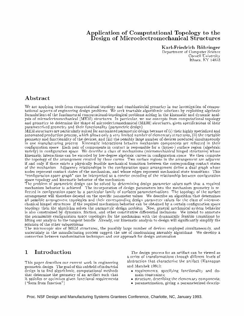
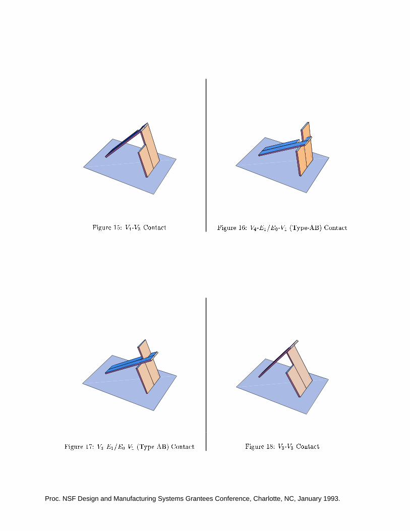
Consider the hinged structure in Figure 7. It con-sists of two cross sections which are shown separatelyin Figures 9 and 11. Their respective con�gurationspaces are shown in Figures 8, 10, and 12. The verticesand edges in the cross sectionmodel are numbered out-ward from the rotational center, from front to back. InFigures 13 to 19 all possible edge-edge, vertex-vertex,and type-AB con�gurations of the hinged mechanismare shown. All pictures were generated automatically(see section 4.6).
4.3 C-Space Graph
As we have seen in the previous section, the behaviorof the system can be describedwith two kinds of states.We distinguish zero-dimensional events (edge-edge,vertex-vertex, type-AB contacts) and one-dimensionaltransitions (edge-vertex, vertex-edge contacts). Usingevents and transitions, we can map the C-space of themechanism to a graph (C-space graph) whose nodesare states and transitions, and whose edges re ect theadjacency relationships of the nodes. This graph canbe seen as a discrete map of the C-space, where curvesegments map into transition nodes, curve endpointsmap into event nodes, and adjacency relationships arepreserved.Note that the C-space graph is bipartite with re-
spect to events and transitions. For a given hingedstructure the number of nodes is O(nPnL) if the platehas nP vertices, and the lock has nL vertices. Thegraph is sparse, because the number of outgoing edgesfor each state is bounded by 2, one each for movingclockwise or counterclockwise on the C-space curve in-�nitesimally.The C-space graph in our model for hinged struc-
tures is the equivalent to the arrangement of C-spacecurves in (Donald and Pai 1992). However, in the C-space graph only the intersections of the curves arecomputed explicitly. Each curve segment is describedby a single transition node. This means no loss of in-formation, because all points on this curve segmentobey the same equations. Thus each node of the C-space graph can be seen as a class of equivalent be-havior of the mechanism.Each cross section of a mechanism generates a sep-
arate C-space, and thus a C-space graph. The freespace of the entire mechanism is the \geometric AND"of the free space of all cross sections. Intersectionsof C-space curves specify con�gurations where partsin two cross sections are in contact. If the mecha-nism's con�guration moves through such an intersec-tion point, the contact changes from one cross sectionto another. In our model this happens only in type-ABnodes. Figures 21 and 22 show the C-space graphs offront and back part of the mechanism described earlierin section 4.2. Events are shown as rectangles, transi-tions as diamonds. The graphs look somewhat trivial,but in fact for a two-dimensional C-space only lineargraphs and simple loops are possible. For a three-dimensional C-space all C-space graphs are planar.The combined graph for both cross sections is shown

Proc. NSF Design and Manufacturing Systems Grantees Conference, Charlotte, NC, January 1993.
-V0
-E0
-V1
� V2
� E1
� V3
� V4� E2
� V5
-V0
-E0
-V1� V2
� E1
� V3
�
�6
�L
6
�PV | vertex
E | edge
� | angle
-0.75 -0.5 -0.25 0 0.25 0.5 0.75 10
0.2
0.4
0.6
0.8
1
cos�P
cos�L
Figure 7: A Hinged Structure Figure 8: C-Space of Hinged Structure
-0.75 -0.5 -0.25 0 0.25 0.5 0.75 10
0.2
0.4
0.6
0.8
1
cos�P
cos�L
Figure 9: V1-V1 (Vertex-Vertex) Contact of FrontPart
Figure 10: C-Space of Front Part

Proc. NSF Design and Manufacturing Systems Grantees Conference, Charlotte, NC, January 1993.
-0.75 -0.5 -0.25 0 0.25 0.5 0.75 10
0.2
0.4
0.6
0.8
1
cos�P
cos�L
Figure 11: V5-V3 (Vertex-Vertex) Contact ofBack Part
Figure 12: C-Space of Back Part
Figure 13: E2-E1 (Edge-Edge) Contact Figure 14: V5-V3 Contact
Proc. NSF Design and Manufacturing Systems Grantees Conference, Charlotte, NC, January 1993.
Figure 15: V4-V3 Contact Figure 16: V4-E1/E0-V1 (Type-AB) Contact
Figure 17: V3-E1/E0-V1 (Type-AB) Contact Figure 18: V3-V3 Contact

Proc. NSF Design and Manufacturing Systems Grantees Conference, Charlotte, NC, January 1993.
Figure 19: E1-E1 Contact Figure 20: Illegal Con�guration
E(0)-E(0)-7
E(0)-V(1)
E(0)-E(0)-10
V(1)-E(0)
V(1)-V(1)
E(0)-E(0)-4
V(1)-E(0)
E(0)-E(0)-7
E(0)-V(1)
E(1)-E(0)-8
V(2)-E(0)
E(1)-E(0)-10
V(3)-E(0)
E(1)-V(1)
V(1)-V(1)
V(2)-V(1)
V(3)-V(1)
Figure 21: C-Space Graph of Front Part Figure 22: C-Space Graph of Back Part

Proc. NSF Design and Manufacturing Systems Grantees Conference, Charlotte, NC, January 1993.
E(0)-E(0)-7
E(0)-V(1)
E(0)-E(0)-10
V(1)-E(0)
E(1)-E(1)-4
V(3)-E(1)
E(1)-E(1)-7
E(1)-V(3)
E(2)-E(1)-8
V(4)-E(1)
E(2)-E(1)-10
V(5)-E(1)
E(2)-V(3)
V(1)-V(1)
V(3)-E(1) E(0)-V(1)
V(3)-V(3)
V(4)-E(1) E(0)-V(1)
V(4)-V(3)
V(5)-V(3)
Figure 23: C-Space Graph of Hinged Mechanism
in Figure 23. Ellipses denote type-AB events, theiredges to transitions (shown as dotted arrows) \domi-nate" edges within the C-space graph of the cross sec-tion, i.e. if the mechanism is in motion, it will followthe transition denoted by the dotted line, due to kine-matic constraints between di�erent cross sections. Re-call that whenever the mechanism goes through sucha transition, the contact region changes from one crosssection to another.Therefore some nodes in the combined graph be-
come unreachable. Figure 20 shows a con�gurationwhere edge E0 of the lock is in contact with vertex V1of the plate. This con�guration would be possible forthe front cross section, but is impossible because theparts in the back cross section would overlap. In Fig-ure 23 we can see that when going counterclockwise(see below) from node \E0-V1" the edge to type-ABnode \V4-E1/E0-V1" dominates the edge to node \V1-V1."Some more notes on the C-space graphs in Fig-
ures 21 to 23.� Edges in the graph are directed. Moving in di-rection of an arc corresponds moving clockwisearound a C-space obstacle, i.e. with the obstacleto the right.
� For each edge-edge contact, we distinguish be-tween di�erent possible con�gurations. This isnecessary because we neglect the vertical thick-ness of lock L and plate P , so there may be acontact on either side of an edge, depending onwhether L or P are at angles (�P ; �L) = (0; 0),(0; �=2), or (�=2; �=2), and whether L is above orbelow P .
� Several extensions for this graph are possible. Inparticular, one could imagine a labeling of nodesand edges. These labels could include informationabout dynamics (see section 3.3) or probabilitiesof state changes (see section 5).
4.4 Parameterized C-Space Graphs
We are now ready to get back to the original prob-lem of mechanism design. Consider a simple example.Let's assume that the mechanism in Figures 13 to 19has one design parameter x that determines the lengthof the front part of the plate. I.e. x is the length ofthe plate (the right part) in Figure 9. The C-spaceand therefore also the C-space graph of the parame-terized mechanism will depend on this design param-eter. More speci�cally, many nodes and edges willonly exist for certain ranges of values for x. Figure 24shows the C-space graph for the parameterized mech-anism. All nodes whose existence depends on x havetheir conditions on the design parameter x attached.For our model of hinged structures, all constraints areconjunctions of linear inequalities.Alternatively the design parameters could be viewed
as generating a generalized con�guration space (Pai1988; Donald 1989) with one additional dimension foreach design parameter, and a family ofC-space graphs.Figure 25 shows the generalized C-space for the pa-rameterized mechanism mentioned above. The designparameter x corresponds to the vertical axis. Each

Proc. NSF Design and Manufacturing Systems Grantees Conference, Charlotte, NC, January 1993.
E(0)-E(0)-0
--------------- (>= -17/4 (- 7/2 X))
V(1)-E(0) ---------------
(> 17/4 (- 7/2 X)) (< 17/4 (+ 7/2 X))
E(0)-E(0)-1
--------------- (< -17/4 (- 7/2 X))
(>= 0 (- 7/2 X))
E(0)-V(1) --------------- (> X 0)
(> 17/4 (- X 7/2)) (> 17/4 (- 7/2 X))
(< 0 (+ 7/2 X))
E(0)-E(0)-7
--------------- (<= 0 (- 7/2 X))
(> 17/4 (- 7/2 X))
E(0)-E(0)-10
--------------- (< 17/4 (+ 7/2 X))
E(0)-E(0)-11
--------------- (>= 17/4 (+ 7/2 X))
(< 0 (+ 7/2 X))
E(1)-E(1)-4
V(3)-E(1)
E(1)-E(1)-7
E(1)-V(3)
E(2)-E(1)-8
V(4)-E(1)
E(2)-E(1)-10
V(5)-E(1)
E(2)-V(3)
V(1)-V(1)
--------------- (> X 0)
(> 17/4 (- X 7/2)) (> 17/4 (- 7/2 X)) (< 17/4 (+ 7/2 X))
V(3)-E(1) E(0)-V(1)
--------------- (> X 0)
(> 13/4 (- X 7/2)) (> 13/4 (- 7/2 X)) (< 13/4 (+ 7/2 X))
(> X 0) (< X 3)
V(3)-V(3)
V(4)-E(1) E(0)-V(1)
--------------- (> X 0)
(> 15/4 (- X 7/2)) (> 15/4 (- 7/2 X)) (< 15/4 (+ 7/2 X))
(> X 0) (< X 3)
V(4)-V(3)
V(5)-V(3)
Figure 24: Parameterized C-Space Graph of Hinged Mechanism

Proc. NSF Design and Manufacturing Systems Grantees Conference, Charlotte, NC, January 1993.
slice in the generalized C-space gives the C-space fora particular parameter value, and each C-space graphrepresents the kinematic states of the graph for a par-ticular range of design parameter values. However, inthe following we prefer a single parameterizedC-spacegraph with conditions attached to nodes and edges.
-1-0.5
0
0.5
1
00.5
1
0
2
4
6
8
-1-0.5
0
0.5
1
00.5
1
0
2
4
6
8
Figure 25: Generalized C-Space of Hinged Mechanism
Note that now the graph looks nondeterministic, inthat nodes can have multiple outgoing and incomingedges, corresponding to multiple states as their clock-wise or counterclockwise neighbors. Of course this isnot really an indeterminacy, because by replacing xwith any speci�c value we would get a deterministicgraph. Depending on the value of x the mechanism hasdi�erent states, and therefore exhibits di�erent behav-iors. The parameterized C-space graph in Figure 24are a concise representation for the correlation betweenparameter values and mechanism behavior.
4.5 Design Algorithm Outline
Suppose that the required behavior of a parameterizedmechanism can be speci�ed by a set of desired states.Then an algorithm that \uni�es" this set with a C-space subgraph of the parameterized mechanism candetermine the constraints on the design parameters.In the above example, a design objective would be a
mechanism that has a con�guration in which the mo-tion of the plate is constrained such that it standsup approximately vertically. This con�guration isachieved in the diamond \E0-V1" that is bounded bythe two ellipses \V4-E1/E0-V1" and \V3-E1/E0-V1" inFigure 24 (see also Figures 16 and 17 again). As canbe determined from the constraints in Figure 24, x isrequired to lie in ( 1
4; 3). This makes sense, because if
x � 3 then the front part of the plate is not shorterthan the back part, and the plate cannot �t into theslot in the lock. If x � 1
4then the plate �ts into the
slot in the lock, but the plate's rotational degree of
freedom is not constrained. It is exactly for parame-ter values of x � ( 1
4; 3) that we get back the graph of
Figure 23.
4.6 Implementation
We have started a Lisp implementation of the aboveideas. The current program computes the C-spacegraph for a hinged mechanism. In particular, it gen-erates input for the graph drawing program Dag
(Gansner et al. 1988). It can also generate input forMathematica (Wolfram 1991) to draw the 2D con-�guration space of the mechanism, and 3D picturesof any con�guration. Mathematica is an interactivesystem for mathematical computation. Figures 7 to 24were generated by the program.
For example, this is the Lisp representation of thesample hinged structure from section 4.2:
(make-mechanism(make-part`(,(make-rectangle
(make-interval 0 17/4)(make-interval 1/2 1))
,(make-rectangle(make-interval 0 13/4)(make-interval 1 3/2))
,(make-rectangle(make-interval 15/4 17/4)(make-interval 1 3/2))))
(make-part`(,(make-rectangle
(make-interval 0 (make-parameter x))(make-interval 0 1))
,(make-rectangle(make-interval 0 3)(make-interval 1 2))))
7/2)
In general, a mechanism is de�ned by two parts (lockL and plate P), and their relative distance �. Eachpart consists of a list of rectangles. The dimensionsare speci�ed either by numbers or by symbolic values(design parameters).
The algorithm to construct the C-space graph fromthe geometric description of a hinged structure isshown here:

Proc. NSF Design and Manufacturing Systems Grantees Conference, Charlotte, NC, January 1993.
input: Geometric description of hinged struc-ture (L;P ;�).
output: Its corresponding C-space graph.
for each l in the set of vertices and edges of lockL dofor each p in the set of vertices and
edges of plate P doif there is a con�guration forwhich l and p are in contact
then (1) create node(s) forpair (l; p)
(2) compute the adjacen-cies for new node(s)
end ifend for
end for
For the complexity analysis we assume that the lock Lhas nL vertices, and the plate P has nP vertices. Letus �rst consider the case without parameters. In a sin-gle cross section of the mechanism, each node (events:vertex-vertex, edge-edge; transitions: type-A, type-B)has at most two neighbors. Events and transitionsform a bipartite graph. Graphs of di�erent cross sec-tions are connected via type-AB nodes, which in turnhave two neighbors. From this it follows that steps (1)and (2) in the algorithm above can be computed inO(1) time. O(nLnP ) is the bound for computing theC-space graph, and it is also the bound for the numberof nodes and edges in the graph. Therefore the graphis sparse.Now consider the case when the geometry is param-
eterized. De�ne bnL (bnP ) as the maximum number oflock (plate) vertices in any cross section. Then for eachvertex pair (l; p) there may be up to O(bn
LbnP) type-AB
nodes, because there can be O(bnP ) plate edges thatform a type-A contact with l, and O(bnL) lock edgesthat form a type-B contact with p. Therefore steps(1) and (2) have O(bnLbnP ) worst running time. Thisimplies O(nLbnLnP bnP ) � O(n2
Ln2P) as time bound for
constructing the graph, and as space bound for thenumber of vertices and edges. Note that the introduc-tion of design parameters does not a�ect the sparse-ness of the C-space graph.
5 Randomized Assembly
Randomized strategies for assembly have been pro-posed by many authors. They are used for exam-ple in vibratory bowl feeders (Boothroyd et al. 1977;Boothroyd et al. 1982) to align parts for an assembly.Parts that are not properly aligned after a randomizedorientation phase are �ltered out and oriented again.(Lozano-P�erez 1985) develops ideas for an automaticdesign of these �ltering devices.(Moncevicz et al. 1991) come up with the term of
\shake-and-make assembly" as an ideal assembly pro-cess where devices are assembled by agitated randommotion. For this process to work, the completed as-sembly has to have certain properties. E.g. it should
have a particularly low entropy relative to all possi-ble con�gurations, or the assembly action should beirreversible.(Erdmann 1989; Erdmann 1992) gives a general ap-
proach for probabilistic strategies in robot tasks. Thebasic idea is to use randomized motions whenever theuncertainty in the sensor readings is too large to beof any use for motion planning. This is of particu-lar interest for the assembly of microelectromechanicalstructures. In fact, (Burgett et al. 1992) use a ran-domized strategy to assemble the hinged structuresdescribed in section 2.1, by shaking the wafer underwater such that the randommotion of the water movesthe plates into their �nal position.(Erdmann 1989) investigates randomized strategies
for both discrete and continuous state spaces. Forthe discrete case, he shows that the expected time ofgoal attainment in randomized tasks is low if the statespace of the mechanism can be modeled by Markovchains. This creates a promising connection to C-space graphs. If we label C-space graph edges withprobabilities of being traversed, then we can applythe theory developed in (Erdmann 1989) to predictthe behavior of the mechanism. In particular, we cancompute the probability that a certain desired state isreached. The crucial task now is to determine theseprobabilities. They will depend on both kinematic anddynamic properties of the mechanism.
6 Summary
We have outlined an approach for automation of para-metric design. A model suited for analysis, simu-lation, and design of microelectromechanical hingedstructures was developed. The model compresses thecon�guration space of a mechanism into a concise de-scription of its kinematics, the C-space graph. Fur-ther processing, incorporating dynamics and random-ization, will yield a precise description of the mecha-nism's functionality. The resulting graph will possessthe following properties:
� It gives a concise description of the mechanismbehavior.
� It keeps track of the correspondence between ge-ometric features and functionality of the mecha-nism.
� It forms the basis for algorithms that automateparametric design, by making explicit the rela-tionship between design parameter values andmodes of mechanism operation.
� It provides a framework for analysis of randomassembly strategies.
We believe that our approach, though still in an earlystage, will advance design automation for useful sub-classes of design problems. Models and techniquesthat allow fast, exact analysis and simulation of themechanism to design are crucial for algorithms thatsearch for good designs. Randomization techniqueswill extend the possibilities of algorithms for analy-sis, simulation, and design of mechanisms. Microelec-tromechanical structures o�er a domain in which thesetechniques are extremely useful.

Proc. NSF Design and Manufacturing Systems Grantees Conference, Charlotte, NC, January 1993.
7 Future Goals
At the current stage of our work we want to focus onthe following problems:
� Extend the model by incorporating mechanismdynamics, such as spring forces, and forces of liq-uid ow. This will complete the model of MEMhinged structures.
� Come up with a detailed algorithm (includingcomplexity analysis) for \unifying" C-space sub-graphs. This will form the crucial part of theproposed design algorithm for MEM hinged struc-tures.
� This approach was developed for mechanismswith two-dimensional C-spaces. Investigate ex-tensions for C-spaces with higher dimensions.
� Incorporate randomization techniques into themodel. This will require analyzing the probabilis-tic behavior of the mechanisms. The result will bepredictions on the probabilities for speci�c mech-anism behaviors, and probabilities and expectedtimes for reaching speci�c mechanism states.
� Extend the current implementation to include theitems from above.
� Test the designed mechanisms by building MEMstructures.
Acknowledgements
This paper describes research done in the Roboticsand Vision Laboratory and the Computer ScienceDepartment at Cornell University. Support for ourrobotics research is provided in part by the NationalScience Foundation under grants No. IRI-8802390,IRI-9000532 and by a Presidential Young Investiga-tor award to Bruce Donald, and in part by the AirForce O�ce of Sponsored Research, the MathematicalSciences Institute, Intel Corporation, and AT&T BellLaboratories.Bruce Donald, Srikanth Kannapan (Xerox Design
Research Institute), and Kris Pister (Berkeley) wereof substantial help in writing this paper. Thanks alsoto Vivek Bhatt for his help with Free Body Diagrams.
References
Boothroyd, G.; Poli, C. R.; and Murch, L. E. 1977.Handbook of Feeding and Orienting Techniques forSmall Parts. University of Massachusetts, Amherst,MA. updated July 1981.
Boothroyd, G.; Poli, C. R.; and Murch, L. E. 1982.Automatic Assembly. Marcel Dekker, Inc., New York.
Brooks, Rodney A. and Lozano-P�erez, Tom�as 1982.A subdivision algorithm in con�guration space for�ndpath with rotation. Technical Report A.I. MemoNo. 684, Massachusetts Institute of Technology.
Brost, Randy C. 1989. Computing metric and topo-logical properties of con�guration space obstacles. InProceedings of the IEEE International Conference onRobotics and Automation, Scottsdale, AZ.
Brost, Randy C. 1991. Computing the possible restcon�gurations of two interacting polygons. In Pro-ceedings of the IEEE International Conference onRobotics and Automation.
Burgett, S.R.; Pister, K.S.J.; and Fearing, R.S. 1992.Three dimensional structures made with microfab-ricated hinges. In Micromechanics. ASME WinterAnnual Meeting, Anaheim CA.
Canny, John 1986. Collision detection for movingpolyhedra. IEEE Transactions PAMI 8(2).
Donald, Bruce R. and Pai, Dinesh K. 1989. On themotion of compliantly-connected rigid bodies in con-tact, part ii: A system for analyzing designs for as-sembly. Technical Report TR 89{1048, Cornell Uni-versity, Department of Computer Science, Ithaca, NY14853{7501.
Donald, Bruce R. and Pai, Dinesh 1992. Sym-bolic methods for the simulation of planar mechan-ical systems in design. In Donald, B.; Kapur, D.;and Mundy, J., editors 1992, Symbolic and Numeri-cal Computation for Arti�cial Intelligence. AcademicPress, Cambridge.
Donald, Bruce R. 1987. A search algorithm for mo-tion planning with six degrees of freedom. Arti�cialIntelligence 31(3).
Donald, Bruce R. 1989. Error Detection and Recoveryin Robotics, volume 336 of Lecture Notes in ComputerScience. Springer Verlag, Berlin.
Donald, Bruce R. 1990. Planning multi-step error de-tection and recovery strategies. International Journalof Robotics Research 5(1):3{60.
Erdmann, M. A. 1989. On Probabilistic Strategies forRobot Tasks. Ph.D. Dissertation, Massachusetts In-stitute of Technology, Department of Computer Sci-ence.
Erdmann, M. A. 1992. Randomization in robot tasks.IJRR.
Gansner, E.R.; North, S. C.; and Vo, K. P.1988. DAG: A program that draws directed graphs.Software|Practice and Experience 18(11):1047{1062.
Joskowicz, Leo 1989. Simpli�cation and abstractionof kinematic behaviors. In Proceedings of the 11thInternational Joint Conference on Arti�cial Intelli-gence, Detroit. 1337{1342.
Joskowicz, Leo 1990. Mechanism comparison andclassi�cation in design. Research in Engineering De-sign 1:149{166.
Journal of Microelectromechanical Systems. A JointIEEE and ASME Publication on Microstructures,Microactuators, Microsensors, and Microsystems.
Kannapan, Srikanth M. and Marshek, Kurt M. 1991.Engineering design methodologies: A new perspec-tive. Technical report, The University of Texas atAustin, Austin, Texas 78712{1063.

Proc. NSF Design and Manufacturing Systems Grantees Conference, Charlotte, NC, January 1993.
Lozano-P�erez, Tom�as 1983. Spacial planning: A con-�guration space approach. IEEE Transactions onComputers C-32(2):108{120.
Lozano-P�erez, Tom�as 1985. Towards the automaticdesign of orienting devices for vibratory part feeders.Working draft, Massachusetts Institute of Technol-ogy, Arti�cial Intelligence Laboratory.
Moncevicz, Paul H. Jr.; Jakiela, Mark J.; and Ul-rich, Karl T. 1991. Orientation and insertion of ran-domly presented parts using vibratory agitation. InProceedings of the ASME Flexible Assembly SystemsConference, Miami, Florida.
Pai, Dinesh K. and Donald, Bruce R. 1989. On themotion of compliantly-connected rigid bodies in con-tact, part i: The motion prediction problem. Techni-cal Report TR 89{1047, Cornell University, Depart-ment of Computer Science, Ithaca, NY 14853{7501.
Pai, Dinesh K. 1988. Singularity, Uncertainty andCompliance of Robot Manipulators. Ph.D. Disserta-tion, Cornell University, Ithaca, NY.
Pister, K.S.J.; Judy, M.W.; Burgett, S.R.; andFearing, R.S. 1992. Microfabricated hinges. SAA33(3):249{256.
Whitney, D. E. 1982. Quasi-static assembly of com-pliantly supported rigid parts. Journal of DynamicSystems, Measurement, and Control 104:65{77.
Wolfram, S. 1991. Mathematica: A System for DoingMathematics by Computer. Addison-Wesley, secondedition.