application of atmospheric pressure plasma in ... · application of atmospheric pressure plasma in...
TRANSCRIPT

Proc. 2016 Electrostatics Joint Conference 1
Application of atmospheric pressure
plasma in environmental remediation
and medicine
Kazunori Takashima, Hirofumi Kurita, Hachiro Yasuda and Akira Mizuno
Dept. of Environmental and Life Sciences
Toyohashi University of Technology
phone: (81) 532-44-6921
e-mail: [email protected]
Abstract— Discharge plasma technology is widely studied in various fields such as energy
conversion, semiconductor devices, environmental protection, de-velopment of new materials,
heat and light sources, surface finishing, biology, medicine and so on. We have studied the
application of atmospheric pressure discharge plasma to environmental remediation, biology
and medicine. In this paper, recent progress of our study on diesel exhaust cleaning, ammonia
production, sterilization of bacteria, inactivation of viruses, medical care like cancer treatment
will be introduced briefly.
I. INTRODUCTION
Discharge plasma in gas phase produces energetic electrons, which can collide with
neutral gas molecules to produce gas molecules in excited state, dissociated gas molecules,
ions and electrons. These species can sometimes induce chemical reactions because they
are reactive. Discharge plasma generated at atmospheric pressure using short pulse high
voltage application or application of AC high voltage with dielectric barrier is non-thermal,
in which most electric energy from the high voltage application is delivered to electrons.
Therefore, temperatures of ions and neutrals are nearly the same as room temperature. The
atmospheric pressure non-thermal plasma produced in this way is useful in many fields
because of high energy efficiency, little heat damage to the object, simple structure and easy
operation of plasma generator.
We have studied diesel exhaust cleaning, in which nitrogen oxides (NOx) and partic-
ulate matter (PM) should be removed. NOx was re-moved through selective catalytic re-
action using ammonia (NH3-SCR)[1]. This process works well at high temperatures
(normally 200-250 degree C) to reduce NOx into N2 and H2O but NOx removal efficiency
is low at low temperatures[2] because of low catalytic activity at low temperatures.
Therefore we employed non-thermal plasma in combination with NH3-SCR catalyst to
enhance the reaction at low temperatures[3-7]. PM from diesel engine includes fine parti-
cles ranging from nano to micro meter in diameter[8-10]. A diesel particulate filter, which is

Proc. 2016 Electrostatics Joint Conference 2
made of porous ceramics, is a de-facto standard for diesel PM removal but very high
pressure drop cannot be avoided for the trapping of fine particles[11-12]. Regeneration of
the filter, that is final treatment of PM deposited on a DPF through oxidation (com-bustion),
is another problem to solve. Heat regeneration is normally used but it has a risk of thermal
runaway because of the difficulty in precise temperature control. We investigated an elec-
trostatic precipitator (ESP) to collect diesel PM, which has an advantage that fine par-ticles
can be effectively collected without significant pressure drop. Simultaneous oxidation of
the PM deposited on a collecting electrode in an ESP as well as the regeneration of a DPF
with an assistance of discharge plasma was experimentally studied. Improvement of NH3
generation process is a subject to be studied for on-board NH3-SCR. NH3 is generated by
spraying urea solution into exhaust gas in a commercial NH3-SCR system but it requires
high temperature exhaust, which is not satisfied in some cases. We have studied NH3
genera-tion process at a moderate temperature using discharge plasma and a combination of
discharge plasma and catalyst[13-17]. This method is interesting from a viewpoint of al-
ternatives to Haber-Bosch process, which is a great breakthrough in the 20th century but it
requires high temperatures and very high pressure.
Sterilization of bacteria or inactivation of viruses using non-thermal plasma is useful
because they are room temperature processes and the heat damage to the object can be
ignored. In addition, the process is simple and safe because of no usage of toxic chemicals
and therefore no risk of its residue. Risk of emergence of drug-resistant strains should be
neglected because bacteria are sterilized not by spe-cific interactions between the bacteria
and some chemicals but possibly by non-specific oxidation due to reactive species (radi-
cals) gener-ated by the plasma. We have studied the mechanisms of sterilization and inac-
tivation experimentally[18-22]. Not only direct exposure to the plasma but also exposure to
the water or the liquid medium preprocessed by discharge plasma was found to affect living
cells. For example both the direct and indirect exposure to the plasma can induce cancer cell
apoptosis suggesting that not only very short-life spe-cies directly generated by the plasma
but also stable or meta-stable species generated through some chemical reactions in liquid
phase are associated with the process. We have studied cellular responses to the water and
cell culture medium that were prepared by exposing to atmospheric pressure plas-
ma[23-25].
II. EXPERIMENTAL
A. Electrostatic charging and precipitation of diesel PM
Figure 1 shows a schematic diagram of the experimental setup for PM collection using
an ESP and a DPF. The DPF was installed down-stream of the ESP. A diesel generator
(SUBARU, SGD3000S-III) was used to generate PM. Exhaust gas flow rate was about
900L/min. Exhaust was sampled at downstream of the ESP-DPF combined reactor for PM
number concentration measurement at a rate of 1L/min. The sampled exhaust was diluted
with particle-free N2 gas and then analyzed using an engine exhaust particle sizer (EESP;
TST Ltd, 3090) to measure the number concentration of PM. Figure 2 shows a schematic
illustration of the ESP combined with DPF used in this experiment. It consists of a
100mm-long and 36mm-diameter wire-cylinder type ESP and 128mm-long and
50mm-diameter DPF. Negative DC high voltage was applied to a discharge electrode made

Proc. 2016 Electrostatics Joint Conference 3
of thin SUS wire (0.2mm in diameter) to generate corona discharge in the ESP.
Fig. 1. Schematic diagram of an experimental setup.
Fig. 2. Schematic illustration of an ESP combined with DPF.
B. Suppression of re-entrainment of collected PM
As was described above, ESP has some definite advantages over DPF. However, it has
some problems as well. Re-entrainment of particles is one of the problems that arises es-
pecially for the application to diesel exhaust cleaning. When low-resistance particles such
as diesel PM, which consists of carbon soot, are collected by an ESP, they lose the original
charge and then they are charged oppositely on the collecting electrode. Once particles are
oppositely charged they are detached from the collecting electrode and entrainment into gas
stream due to electrostatic repulsive force. In this way, such particles are subjected to
collection and entrainment repeatedly and finally emitted from an ESP. This is called
“abnormal re-entrainment” and ESP sometimes cannot provide high performance for
conductive particles due to this phenomenon.
We studied an effect of fine structure introduced on the surface of collecting electrode to
cope with this problem. Collection electrode with fine structure can distort the electrostatic
field near the surface probably affect the characteristics of particle re-entrainment. In ad-

Proc. 2016 Electrostatics Joint Conference 4
dition, fine structure should work as a windbreak against gas stream just near the collecting
electrode so that re-entrainment due to air flow should be suppressed.
Figure 3 shows a schematic illustration of an ESP used in this study. It has basically the
same configuration as the one in the previous section but as a discharging electrode, a SUS
rod equipped with some star-shaped electrodes were used in place of a SUS wire. In order to
investigate the influence of the surface structure of the collecting electrode, a SUS mesh
was installed on the colleting electrode to modify the surface roughness. Table 1 shows the
properties of the mesh investigated in this study. A SUS plate having the same thickness as
the stainless steel mesh was also examined to adjust the gap distance between the dis-
charging electrode and the collecting electrode. In this experiment, only ESP was used.
Fig. 3. Schematic illustration of an ESP having collecting electrode with fine structure..
TABLE 1: LIST OF SUS MESH FOR COLLECTING ELECTRODE SURFACE STRUCTURE MODIFICATION
Type (The number of
holes par inch) A [mm] B [mm] Open area [%]
16 0.29 1.30 66.9
18 0.34 1.07 57.6
30 0.25 0.60 49.8
40 0.18 0.46 51.7
120 0.08 0.13 38.3
SUS plate -- -- 0
C. Ammonia generation under moderate condition
Figure 4 shows a dielectric barrier discharge (DBD) reactor used for NH3 generation.
The reactor consists of a quartz glass tube, high voltage and grounded electrodes. Dielectric
pellets were packed inside the glass tube. As a high voltage electrode, a stainless steel wire
of 1.5mm in diameter was placed at the center of the tube. A stainless steel mesh was
wrapped on the outer surface of the glass tube and grounded. DBD shown in figure 4(b) was
generated by applying AC high voltage. Al2O3, TiO2, BaTiO3, CeO2, Ru-Al2O3 were used
as pellet packed in the reactor.

Proc. 2016 Electrostatics Joint Conference 5
Stainless mesh (on the outer
surface of the quartz glass tube)
Quarts glass tube
( Inner diameter 14 mm,
Outer diameter 17 mm )
Stainless steel wire
(High voltage electrode,
1.5 mm in diameter)
Gas inlet100 mm
Gas outlet
(a) DBD reactor
(b) DBD
Fig. 4. Schematic illustration of a DBD reactor.
Figure 5 shows a schematic diagram of an experimental setup. Starting gas was prepared
by mixing N2, NOx and CO and then H2O content was adjusted by saturated water vapor.
The gas was preheated before entering the DBD reactor, which was placed in a convection
oven to control the temperature (120 degree C). Out gas was cooled to separate excess water
content. Gas component was analyzed by FT-IR and liquid component was analyzed by ion
chromatography. NH3 concentration shown in this section is the sum of those detected in
gas and liquid phases.
ion chromato-graphy
Temperature and humidity meter
Reactor
N2 or
mantle heater
Cooling water
Liquid analysis
gas preheated
AC high voltage power supply
H2O was added to the gas stream
NOx+CO
Oscilloscopereactor temperature controled
ribbon heater
oven
water trap
Fig. 5. Schematic illustration of an experimental setup for NH3 generation using DBD.

Proc. 2016 Electrostatics Joint Conference 6
D. Inactivation of viruses using DBD
There are many reports on bacteria and virus inactivation but its mechanism is not fully
understood. We have developed a simple experimental system to investigate virus inacti-
vation mechanism using discharge plasma. In this study, bacteriophage lambda ( phage)
shown in figure 6, which consists of double-stranded linear DNA and coat proteins and
bacteriophage M13 (M13 phage) shown in figure 7, which consists of single-stranded
circular DNA and coat proteins, were used as model virus having the simplest construction.
The advantage of this experimental design is that both DNA and coat proteins of the plasma
processed bacteriophage can be processed molecular biologically. Therefore, damages on
DNA and coat proteins can be separately evaluated.
Coat
protein
DNA
(a) Schematic illustration of phage
In vitro
packaging
Coat proteins
DNA
extraction
Re-packaged
λ phage
λ DNAλ phage
Plasma
(b) Procedure of repackaging of phage
Fig. 6. Assay of phage using repackaging.
Coat proteins
DNA
(a) Schematic illustration of M13 phage
M13 phage (Circular ssDNA)
Infection to E.coli
Survival curve
DNA extraction
and purification
DNA transfection
to E.coli
(Comparison)
Survival curve
(b) Procedure of repackaging of M13 phage
Fig. 7. Assay ofphage using repackaging.

Proc. 2016 Electrostatics Joint Conference 7
Figure 8 shows a schematic illustration of DBD reactor used in this study. The
peak-to-peak voltage and frequency of the AC high voltage and input power were 40kVp-p,
2kHz and 8.7W, respectively. A 20l aliquot of sample suspension was spotted and widely
spread on a hydrophilically augmented PET film. Sample suspension was recovered from
the PET film by adding 40l of distilled water on the PET film after DBD application. The
recovered phage was examined by infection to E. coli both as it was and after repackaging.
Inactivation of M13 phage was analyzed by infection and transfection of extracted DNA to
E. coli. Phage plaques of the infected E. coli. were counted after incubation at 40 degrees C
for 24h.
Ground electrode
Spacer (3mm)
AC High Voltage
40kVp-p, 2kHz
f 50mmElectrode (SUS mesh) Dielectric barrier
(Teflon plate)
SampleHydrophilically augmented PET film
Sample solution
Fig. 8. DBD reactor for bacteriophage inactivation.
E. Cancer cell apoptosis induced by direct and indirect exposure to plasma jet
Atmospheric pressure plasma jet (APPJ) generates charged particles, reactive oxygen
and nitrogen species, UV ray etc. APPJ is actively studied in the field of medical application
with an interest of interaction between cells and APPJ or water and medium that are irra-
diated by APPJ. We have investigated chemical species generated in the plasma-treated cell
culture medium and cancer cell response when it was exposed to the plasma-treated me-
dium. Figure 9 shows APPJ generator. It consisted of a quartz glass tube as a dielectric
barrier, a thin SUS wire as a high voltage electrode and a SUS mesh as a grounded electrode.
By applying pulsed high voltage in the presence of Ar gas flow, DBD was generated and
luminous APPJ was generated from the end of the glass tube. Amplitude, pulse width and
repetitive frequency of the applied voltage were 12kV0-p, 2.8sec, 2.5kHz, respectively. Ar
gas flow rate was 2L/min. H2O2 concentration in plasma treated medium was measured
using Amplex Red reagent and nitrate and nitrite ions were measured by 2
3-diaminonaphthalene assay. Two human lung cancer cell lines, A549 and NCI-H460 were
used to investigate the response of cancer cell plasma-exposed cell culture medium. Via-
bility and cytotoxicity were simultaneously measured by two protease activities associated
with viability and cytotoxicity, respectively. Cell apoptosis were measured by caspase 3/7
acitivities.

Proc. 2016 Electrostatics Joint Conference 8
45 mm
Ar plasma jet
Voltage: 12 kV0-p
Frequency: 2.5 kHzPulse width: 2.8 μsec
Argon stream
2 L/min
Stainless steel mesh
Stainless steel wire
(Φ 0.5 mm)
Inner glass tube
(ID 0.8 mm, OD 2.0 mm)
Outer glass tube
(ID 5.0 mm, OD 7.0 mm)Silicone plug
Silicone plug
Cross-section of
plasma generator
20 mm
5 mm
0.8 mm
400 μl of aqueous solutionSpin trapping solution / Neutral pH
buffer / Cell culture medium
Fig. 9. Schematic illustration of APPJ generator.
III. RESULTS AND DISCUSSION
A. Electrostatic charging and precipitation of diesel PM[26-27]
Figure 10 shows a number concentration and its size distribution of PM in raw diesel
exhaust used in this study. A diesel generator was operated at nearly full load (2.6kW load
against 3.0kW capacity) to obtain dry PM with little soluble organic fraction (SOF). The
figure shows a peak at about 70nm in diameter and most PM was smaller than 200nm.
Fig. 10. Number concentration and size distribution of PM in raw diesel exhaust.
Figure 11 shows time change of PM removal ratio when only ESP was operated (DPF
was not installed). The applied voltage to the ESP was -12.5kV and the resulting current
ranged from -0.45mA to -1.25mA. Removal ratio was calculated from the data when ESP
was on and off. The number concentrations at 69.8nm of diameter, where the size distri-
bution has a peak, was used for calculating PM removal ratio unless otherwise noted in this

Proc. 2016 Electrostatics Joint Conference 9
section. Approximately 95% of the PM was removed when the ESP was on.
Fig. 11. Time change in PM concentration (at 69.8nm in diameter) when ESP was on.
Figure 12(a) shows PM removal ratio using ESP-DPF combined system when ESP was
on and off. The ESP was operated under the same condition as figure 11. Around 98% of
the removal rate was obtained when ESP was off, meaning the removal rate of DPF alone.
When ESP was on, removal ratio nearly 100% was obtained suggesting that fine PM was
completely removed by the combination of ESP and DPF. Assuming that ESP and DPF
work independently, PM penetration ratio when both ESP and DPF is used can be esti-
mated from the removal ratios of ESP and DPF as follows:
XE+D = XE×XD = 0.05×0.02 [-] = 0.1[%]
where XE and XD are the penetration ratios of a single use of ESP and DPF respectively.
Figure 12(b) shows averaged penetration ratio during the simultaneous operation of ESP
and DPF was about 0.024%, which is significantly smaller than the above estimated value,
suggesting a certain synergetic effect of simultaneous operation of ESP and DPF.
0.001
0.01
0.1
1
10
0 20 40 60 80
Penetr
ation r
atio [
%]
Time [min]
0.024
ESP
ON
ESP
ON
ESP
ON
ESP
ON
(a) removal ratio (b) penetration ratio
Fig. 12. Removal and penetration ratios of diesel PM using ESP-DPF combined system when ESP was on and off.

Proc. 2016 Electrostatics Joint Conference 10
In order to investigate the agglomeration of diesel PM during passing through the ESP,
exhaust was filtered by a quartz fiber filter at downstream of the ESP and observed with
SEM. Figure 13 shows SEM images of a quartz fiber filter. No particle was observed on a
new filter (a). Small particles were observed on a filter that through which diesel exhaust
was filtered without operating the ESP (b). When ESP was on, a number of particles were
collected on a filter (c). It is also found that particles formed secondary structure like a tree
and that particles as large as a few micron were observed (d). These results suggest that
primary particles can agglomerate in ESP probably because particles are subjected to the
process of collection and re-entrainment repeatedly. Therefore, ESP can be said to work not
only as a collecting device but also an agglomerating device.
(a) new filter (b) ESP off
(c) ESP on (d) ESP on
Fig. 13. SEM images of the PM collected on a quartz fiber filter.
Figure 14 shows a time-lapse change of the pressure drop of the ESP-DPF combined
system. Pressure drop across the DPF rapidly (4.7kPa /min) increased with time in an
exponential manner when ESP was not operated. On the other hand, pressure drop in-
creased very gradually (0.08kPa/min) when ESP was on. Increase in the pressure drop
means the blocking of DPF because the pressure drop arises only in the DPF in this case.
Therefore, simultaneous operation of the ESP at upstream the DPF significantly reduced
blocking of the DPF. The significant difference in filter blocking speed by a factor of ap-
proximately 50 should be resulted from the difference in particle agglomeration. As was
mentioned above, the number fine particles reduced and small number of large particles
were found at downstream of ESP when ESP was on. Such large particles should be col-
lected just on the DPF surface less closely so that blocking of the small pore of the DPF
should be suppressed. On the other hand, a number of fine particles can penetrate deeply
inside the pore so that the pore is packed with fine particles densely, resulting in significant
and rapid increase in pressure drop.

Proc. 2016 Electrostatics Joint Conference 11
Fig. 14. Time-lapse change in pressure drop across DEP with and without simultaneous operation of ESP.
B. Suppression of re-entrainment of collected PM[28-29]
ESP was operated with negative high voltage of -10kV. Diesel generator was operated
at middle load (1.8kW load against 3.0kW capacity) and the exhaust temperature was
adjusted to 60°C by forced air cooling. Figure 15 shows photos of the SUS mesh placed on
the collecting electrode. PM deposition significantly varied with the type of mesh. Gener-
ally, PM deposited on coarse meshes has highly branched structure like a tree but PM
deposited on fine meshes has even and flat structure.
Fig. 15. Photographs of SUS mesh and SUS plate installed on the collecting electrode of ESP.
Figure 16 shows PM removal efficiency of each mesh 10 minutes after the starting the
experiment. In any cases using collecting electrode having rough surface showed higher PM
removal rate compared with that of normal ESP. The 18 mesh showed the highest removal
efficiency of 91.6%. But unexpectedly, particle deposition on the 18 mesh was least sig-
nificant. From these result we can assume that the particles were collected in the narrow
space between the mesh and the collecting electrode in this case in the following way:
Particles are collected on a mesh element and the coagulated particles entered the space
between the mesh and the collection plate, where abnormal re-entrainment into the gas
stream is unlikely to occur. Ionic wind going toward the collecting electrode might helped
falling down of the coagulated particles into the narrow space. In addition, collection effi-

Proc. 2016 Electrostatics Joint Conference 12
ciency was significantly affected by types of mesh suggesting that roughness of the col-
lecting electrode affect the “PM intake” phenomenon. Further investigation should be
carried out to analyze the correlation of the surface roughness of the collecting plate and the
collection efficiency so that we can elucidate the mechanism.
Fig. 16. Comparison of PM removal efficiency among various meshes.
C. Ammonia generation under moderate condition[13-14]
Figure 17 shows NH3 and NOx concentration generated by using DBD reactor packed
with various catalyst. When Ru supported on Al2O3 was used as catalyst and the starting gas
contained CO, but NH3 was generated but significant NH3 generation was not observed in
other experimental condition. No NH3 was generated without DBD plasma suggesting that
NH3 was generated through plasma catalytic reaction in which CO plays an important role.
Figure 18 shows correlation between NH3 concentration and water content when Ru-Al2O3
was used in the presence of 1000ppm CO. The highest NH3 concentration was observed
when water content was 1.2%. NH3 generation was low when water content was low
probably because of too little hydrogen atoms and NH3 generation was low when water
content was high probably because of much oxygen atoms. CO could have worked as a
scavenger of oxygen atoms by reacting with oxygen atom to form CO2.
NH
3co
nce
ntr
atio
n[
pp
m ]
H2O content[ % ]
○Without CO ●With CO
γ-Al2O3 BaTiO3TiO2 CeO2
Ru-Al2O3 γ-Al2O3 BaTiO3TiO2
Fig. 17. Concentration of NH3 generated by DBD and various catalyst pellets with and without CO (1000ppm).
Proc. 2016 Electrostatics Joint Conference 13
●NH3
○NOX
Catalyst:Ru-Al2O3
0
10
20
30
40
50
60
0 2 4 6 8 10
Co
nce
ntr
ation
[pp
m]
H2O content [%]
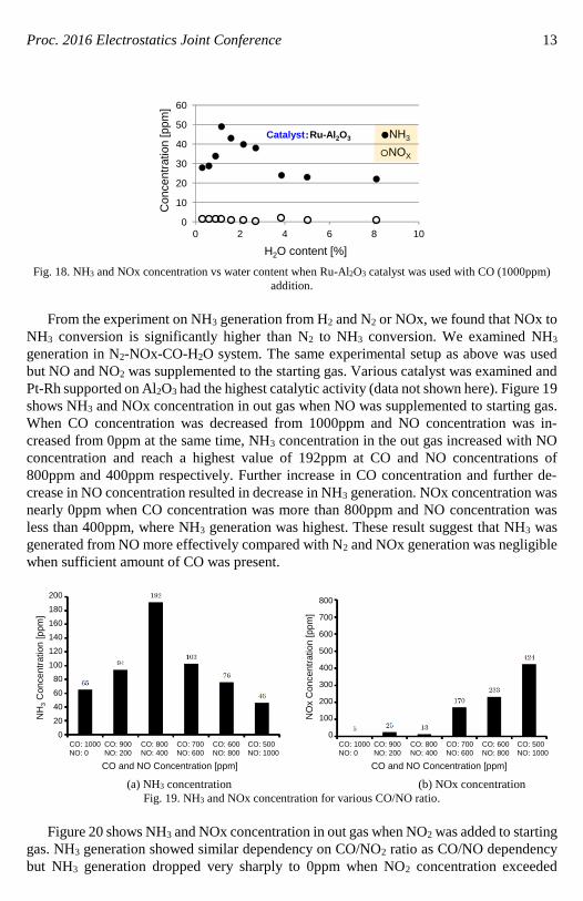
Fig. 18. NH3 and NOx concentration vs water content when Ru-Al2O3 catalyst was used with CO (1000ppm)
addition.
From the experiment on NH3 generation from H2 and N2 or NOx, we found that NOx to
NH3 conversion is significantly higher than N2 to NH3 conversion. We examined NH3
generation in N2-NOx-CO-H2O system. The same experimental setup as above was used
but NO and NO2 was supplemented to the starting gas. Various catalyst was examined and
Pt-Rh supported on Al2O3 had the highest catalytic activity (data not shown here). Figure 19
shows NH3 and NOx concentration in out gas when NO was supplemented to starting gas.
When CO concentration was decreased from 1000ppm and NO concentration was in-
creased from 0ppm at the same time, NH3 concentration in the out gas increased with NO
concentration and reach a highest value of 192ppm at CO and NO concentrations of
800ppm and 400ppm respectively. Further increase in CO concentration and further de-
crease in NO concentration resulted in decrease in NH3 generation. NOx concentration was
nearly 0ppm when CO concentration was more than 800ppm and NO concentration was
less than 400ppm, where NH3 generation was highest. These result suggest that NH3 was
generated from NO more effectively compared with N2 and NOx generation was negligible
when sufficient amount of CO was present.
200
NH
3C
on
cen
tratio
n [
ppm
]
0
20
40
60
80
100
120
140
160
180
CO: 1000
NO: 0
CO and NO Concentration [ppm]
CO: 900
NO: 200
CO: 800
NO: 400
CO: 700
NO: 600
CO: 600
NO: 800
CO: 500
NO: 1000
NO
x C
on
cen
tratio
n [
ppm
]
0
100
200
300
400
500
600
700
800
CO: 1000
NO: 0
CO and NO Concentration [ppm]
CO: 900
NO: 200
CO: 800
NO: 400
CO: 700
NO: 600
CO: 600
NO: 800
CO: 500
NO: 1000
(a) NH3 concentration (b) NOx concentration
Fig. 19. NH3 and NOx concentration for various CO/NO ratio.
Figure 20 shows NH3 and NOx concentration in out gas when NO2 was added to starting
gas. NH3 generation showed similar dependency on CO/NO2 ratio as CO/NO dependency
but NH3 generation dropped very sharply to 0ppm when NO2 concentration exceeded

Proc. 2016 Electrostatics Joint Conference 14
400ppm. Similarly, NOx generation increased more significantly with increasing NO2
concentration compared with the case of NO addition. These results suggest that NO2 is
more reactive than N2 to generate NH3 but more oxidative, which can inhibit NH3 genera-
tion in the presence of excessive amount of NO2.
200
NH
3C
oncentr
ation [
ppm
]
0
20
40
60
80
100
120
140
160
180
CO: 1000
NO2: 0
CO and NO2 Concentration [ppm]
CO: 900
NO2: 200
CO: 800
NO2: 400
CO: 700
NO2: 600
CO: 600
NO2: 800
CO: 500
NO2: 1000
NO
x C
oncentr
ation [
ppm
]0
100
200
300
400
500
600
700
800
CO: 1000
NO2: 0
CO and NO2 Concentration [ppm]
CO: 900
NO2: 200
CO: 800
NO2: 400
CO: 700
NO2: 600
CO: 600
NO2: 800
CO: 500
NO2: 1000
(a) NH3 concentration (b) NOx concentration
Fig. 20. NH3 and NOx concentration for various CO/NO2 ratio.
D. Inactivation of viruses using DBD[18, 21]
Figure 21 shows inactivation characteristics of the phage. Infectivity of the plasma
processed phage decreased rapidly with plasma exposure time and inactivated by a factor
of 10-6 after 20sec. Damage associated with this inactivation should exist in DNA or coat
proteins or both of them. On the other hand, repackaged phage, of which coat proteins
were renewed after plasma exposure and therefore the phage has no damage on coat pro-
teins, showed significantly gradual inactivation characteristics. Only 1 order of magnitude
of inactivation was observed for the repackaged phage. This significant difference should
be resulted from the difference in damage on coat proteins suggesting that plasma inacti-
vation of phage is mostly attributed to damage on coat proteins.
Fig. 21. Infectivity of phages subjected to the atmospheric pressure DBD.
Figure 22 shows electrophoretic analysis of coat protein and DNA of the plasma ex-
posed phage. From figure 22(a), coat protein has no significant decrease in amount until

Proc. 2016 Electrostatics Joint Conference 15
20sec of plasma exposure, which significantly inactivated phage. However the major
band in figure 22(a) gradually shifted to upper side with the exposure time. These result
suggest that exposure to the plasma caused some chemical modification to the coat proteins.
From figure 22(b), DNA was not seriously damaged until 20sec of plasma exposure similar
to the coat protein. This result agrees well with the result of infectivity of the repackaged
phage. Judging from these results, plasma inactivation of phage is probably induced by
chemical modification of the coat proteins.
(a) Coat proteins (b) DNA
Fig. 22. Electrophoretic analysis of coat protein and DNA of the plasma exposed phage.
Figure 23 shows inactivation characteristics of the M13 phage. Unlike phage, both
infection of plasma exposed M13 phage and transfection of the DNA extracted from the
plasma processed M13 phage showed similar curves. The inactivation of transfected DNA
was resulted from the only damage on DNA itself while inactivation of M13 phage were
induced by damages on both DNA and coat proteins. Therefore, little difference between
them suggests that with regards to the plasma inactivation of M13 phage, damage on the
coat protein is comparable or negligible compared with damage on DNA. Opposite to
phage, DNA damage played a significant role in inactivating M13 phage probably because
single-stranded DNA of M13 phage is very fragile and it is damaged easily and signifi-
cantly.
0 5 10 15 20 25 30
Treatment time [sec]
PF
U [
/ml]
100
10-1
10-2
10-3
10-4
10-5
M13 phage
DNA transfection
Fig. 23. Infectivity of M13 phages subjected to the atmospheric pressure DBD.

Proc. 2016 Electrostatics Joint Conference 16
E. Cancer cell apoptosis induced by direct and indirect exposure to plasma jet[30]
Figure 24 shows H2O2, NO-, NO2- concentrations in the cell culture medium exposed to
APPJ for 10min. Gap between APPJ generator and the medium was 45mm and the applied
voltage was 12kV0-p. From these results carried out using serially diluted plasma exposed
medium, concentrations of H2O2, NO-, NO2- in undiluted medium were estimated at 0.3mM,
0.3mM and 0.03mM, respectively. From a viewpoint of quantity, H2O2 and NO- are the
major species produced in plasma-exposed medium.
Fluorometric assay with
2, 3-diaminonaphthalene
and NO3 reductase
10 min. exposure
0 2 4 6
5
10
15
20
[Plasma−exposed medium] [%]
[H2O
2] [
M]
Fluorometric assay with
Amplex Red and peroxidase
10 min. exposure
(a) NO- and NO2
- concentration (b) H2O2 concentration
Fig. 24. H2O2, NO-, NO2- concentrations in the cell culture medium exposed to APPJ.
Then we investigated cellular responses to the plasma-exposed medium. Figure 25
shows cellular responses of two different human lung cancer cell lines (A549 and
NCI-H460) after 8-hour culture in the various concentrations of plasma-exposed medium
(solid line). Dotted line shows the cellular response when they were cultured in medium
supplemented with H2O2, which was not exposed to APPJ. Cell viability relative to that of
untreated cell (UTC) was plotted on the left vertical axis. Indexes of apoptosis and cyto-
toxicity relative to UTC were plotted on the right vertical axis. A549 and NCI-H460
showed qualitatively similar but quantitatively different response to the concentrations of
plasma-exposed medium and H2O2. The first and the second horizontal axes are calibrated
to each other. Viability reduced with increase in concentrations of plasma-exposed medium
and H2O2. Apoptosis and cytotoxicity seems to have a threshold for the concentrations of
plasma-exposed medium and H2O2. Figure 26 shows cell responses (viability, apoptosis
and cytotoxicity indexes) of human lung cancer cell lines A549 and NCI-H460 after
16-hour culture. These results shows similar tendency as figure 26. It is interesting to point
out that all the cellular responses (viability, apoptosis and cytotoxicity) investigated in this
study can be accounted for by H2O2 concentration in the medium not depending on how the
medium was prepared. It was strongly suggested that effect of plasma-exposed medium on
these cancer cell lines is mainly ascribable to H2O2.

Proc. 2016 Electrostatics Joint Conference 17
NCI-H460A549
(a) A549 (b) NCI-H460
Fig. 25. Cellular responses of human lung cancer cell lines after 8 hours.
NCI-H460A549
(a) A549 (b) NCI-H460
Fig. 26. Cellular responses of human lung cancer cell lines after 16 hours.

Proc. 2016 Electrostatics Joint Conference 18
IV. CONCLUSION
Combination of electrostatic precipitator (ESP) and diesel particulate filter (DPF) were
found effective for diesel PM collection because it significantly reduced pressure drop
increase associated with blocking of DPF probably because of coagulation of PM due to
abnormal re-entrainment in ESP. Fine structure introduced by a SUS mesh placed on the
surface of collection electrode of ESP enhanced PM removal ratio possibly because of PM
transfer into the narrow space between SUS mesh and collecting electrode. Plasma cata-
lytic NH3 generation from N2 and H2O was significantly enhanced by adding NO and CO
suggesting that NO reacts with H2O effectively in the presence of CO. Plasma inactivation
of and M13phages were induced by fatal damage of coat proteins and DNA, respectively
depending on the difference in nature of double-stranded and single-stranded DNA. Cel-
lular responses in both A549 and NCI-H460 human lung cancer cell lines showed that the
plasma-exposed medium and the H2O2 treatment gave similar reduction in viability and
induction of apoptosis. Thus, H2O2 should be the major cause of these cellular responses.
REFERENCES
[1] T. Johnson, “Diesel Emission Control in Review”, SAE Technical paper, 2001-01-0184 (2001).
[2] M. Okubo et al., “Air and water pollution control technologies using atmospheric pressure low-temperature
plasma hybrid process”, J. Plasma Fusion Res., Vol.189, pp.152-157 (2013).
[3] K. Takashima et al., “Honeycomb Discharge Generated with a Single High Voltage Power Supply for
Activating Catalyst”, International Journal of Plasma Environmental Science and Technology, Vol.7,
pp.142-147 (2013).
[4] J. Jolibois et al., “NOx Removal Using a Non-thermal Surface Plasma Discharge Powered by a Modulated
Voltage”, International Journal of Plasma Environmental Science and Technology, Vol.6, pp.74-80 (2012).
[5] S. Sato et al., “The study of NOx reduction using plasma-assisted SCR system for a heavy duty diesel
engine”, SAE Technical Paper, 2011-01-0310 (2011).
[6] S. Sato et al., “NOx Removal of Simulated Diesel Exhaust with Honeycomb Discharge”, International
Journal of Plasma Environmental Science and Technology, Vol.4, pp.18-23 (2010).
[7] S. Sato et al., “Honeycomb discharge for diesel exhaust cleaning”, Journal of Electrostatics, Vol.67,
pp.77-83 (2009).
[8] D.B. Kittelson, “Engines and nanoparticles: A review”, J. Aerosol Sci., Vol.29, pp.575-588 (1998).
[9] H. Burtscher, “Physical characterization of particulate emissions from diesel engines: A review”, J. Aerosol
Sci., Vol.36, pp.896-932 (2005).
[10] M.M. Maricq, “Chemical characterization of particulate emissions from diesel engines: A review”, J.
Aerosol Sci., Vol.38, pp.1079-1118 (2007).
[11] J. Adler, “Ceramic diesel particulate filters”, Intl. J. Appl. Ceramic Technology, Vol.2, pp.429-439 (2005).
[12] M. Okubo et al., “Low-temperature soot incineration of diesel particulate filter using remote nonthermal
plasma induced by a pulsed barrier discharge”, IEEE Trans. on Industry Appl., Vol.40, pp.1504-1512
(2004).
[13] T. Shimoda et al. “Ammonia Production Using Packed Bed Electric Discharge and Catalyst”, presented at
the ISPlasma2015 / IC-PLANTS2015, Nagoya, Japan, March 26-31, 2015, A4-P-18. (2015).
[14] K. Yamasaki et al., “Ammonia generation using electric discharge plasma generated in steam”, Interna-
tional Journal of Plasma Environmental Science and Technology, vol.8, pp.113-116 (2014)
[15] G. Prieto et al., “Dielectric barrier discharge for ammonia production”, Plasma Chemistry and Plasma
Processing, Vol.33, pp.337-353 (2013).
[16] Y. Iitsuka et al., “Ammonia production from solid urea using non-thermal plasma”, IEEE Transactions on
Industry Applications, Vol.48, pp.872-877 (2012).
[17] S. Mededovic Thagard et al., “Analysis of the By-Products in the Ammonia Production From Urea by
Dielectric Barrier Discharge”, IEEE Transactions on Plasma Science, Vol.37, pp.444-448 (2009).

Proc. 2016 Electrostatics Joint Conference 19
[18] Y. Tanaka et al., “Analysis of the inactivation mechanism of bacteriophage φX174 by atmospheric pressure
discharge plasma”, IEEE Transactions on Industry Applications, Vol.50, pp.1397-1401 (2014).
[19] T. Nakajima et al., “The Relation of E. coli Growth Phase and Low-Temperature He Plasma Jet Exposure”,
International Journal of Plasma Environmental Science and Technology, Vol.6, pp.189-193 (2012).
[20] T. Nakajima et al., “Generation of Bactericidal Factors in the Liquid Phase and Approach to New Gene
Transfer Technology by Low Temperature Plasma Jet Treatment”, International Journal of Plasma Envi-
ronmental Science and Technology, Vol.5, pp.42-49 (2011).
[21] H. Yasuda et al., “Biological evaluation of DNA damage in bacteriophages inactivated by atmospheric
pressure cold plasma”, Plasma Processes and Polymers, Vol. 7, pp.301–308 (2010).
[22] H. Yasuda et al., “States of Biological Components in Bacteria and Bacteriophages during Inactivation by
Atmospheric Dielectric Barrier Discharges”, Plasma Processes and Polymers, Vol.5, pp.615-621 (2008).
[23] H. Kurita et al., “Use of molecular beacons for the rapid analysis of DNA damage induced by exposure to an
atmospheric pressure plasma jet”, Applied Physics Letters, Vol.107, 263702 (5 pp.) (2015).
[24] H. Kurita et al., “Radical reaction in aqueous media injected by atmospheric pressure plasma jet and
protective effect of antioxidant reagents evaluated by single-molecule DNA measurement”, Japanese
Journal of Applied Physics, Vol.53, 05FR01A (4 pp.) (2014).
[25] K. Sano et al., “Evaluation of reactive oxygen species in non-thermal plasma-treated water”, International
Journal of Plasma Environmental Science and Technology, Vol.8, pp.149-153 (2014).
[26] H. Hayashi et al., “Collection of Diesel Exhaust Particles using Electrostatic Charging prior to DPF and
Regeneration of DPF using Sliding Discharge”, International Journal of Plasma Environmental Science and
Technology, Vol.6, pp.160-165 (2012).
[27] H. Hayashi et al., “Electrostatic Charging and Precipitation of Diesel Soot”, IEEE Transactions on Industry
Applications, Vol.47, pp.331-335 (2011).
[28] M. Takasaki et al. “Electrostatic precipitation of diesel PM at reduced gas temperature”, IEEE Transactions
on Industry Applications, submitted.
[29] M. Takasaki et al. “Improvement of Collection Efficiency for Diesel Particulate Matter Installed with
Ceramic Foam on a Collection Plate of an Electrostatic Precipitator”, presented at the ISPlasma2015 /
IC-PLANTS2015, Nagoya, Japan, March 26-31, 2015, A4-P-11. (2015).
[30] H. Kurita et al. “ROS detection and cellular responses induced by atmospheric pressure plasma exposure”,
presented at the ISPlasma2015 / IC-PLANTS2015, Nagoya, Japan, March 26-31, 2015, D4-O-06. (2015).