application of advanced materials and new … · application of advanced materials and new...
TRANSCRIPT
Application of Advanced Materials and New Detailing for ABC
Column ConnectionsMostafa Tazarv, PhD
Assistant Professor
Department of Civil and Environmental Engineering
South Dakota State University (SDSU)
Presentation Prepared for ABC-UTC
Jan. 29, 2016
Outline
- Intro to ABC Column Connections
- Advanced Materials
- UHPC-Filled Duct Connections
- Low-Damage Precast Columns
-Columns w/ Couplers
-Cap Beam Pocket Connections
2
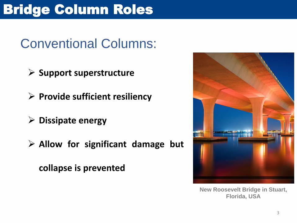
Bridge Column Roles
Conventional Columns:
Support superstructure
Provide sufficient resiliency
Dissipate energy
Allow for significant damage but
collapse is prevented
3
New Roosevelt Bridge in Stuart, Florida, USA
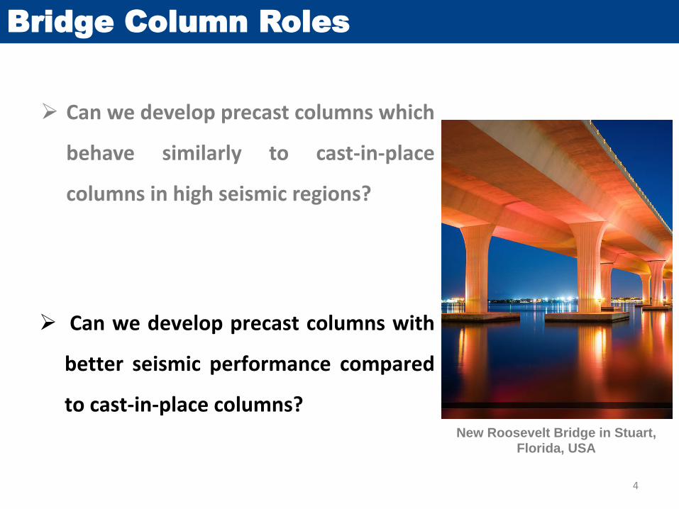
Bridge Column Roles
Can we develop precast columns with
better seismic performance compared
to cast-in-place columns?
Can we develop precast columns which
behave similarly to cast-in-place
columns in high seismic regions?
4
New Roosevelt Bridge in Stuart, Florida, USA

Column Connections:
Precast Column Connections
Column to Cap Beam
Column to
Footing
Pocket Connection Grouted Duct Connection Rocking Connection Bar Coupler Connection Pipe-pin connection Novel Plastic Hinges
Pocket/Socket Connection Grouted Duct Connection Rocking Connection Bar Coupler Connection Pipe-pin Connection Novel Plastic Hinges
5
Novel Materials
Introduction
6

Advanced Materials
Advanced Materials:
Reduce damage, reduce residual strains,enhance compressive and tensile strengths ofconcrete, enhance durability, and many more
Shape Memory Alloy (SMA)
Ultra-High Performance Concrete (UHPC)
Engineered Cementitious Composite (ECC)
Fiber Reinforced Polymer (FRP)
Built-in Rubber Pad
7
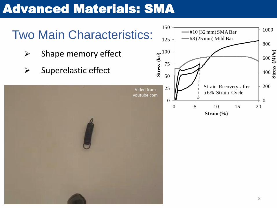
Advanced Materials: SMA
Shape memory effect
Superelastic effect
0
200
400
600
800
1000
0
25
50
75
100
125
150
0 5 10 15 20
Str
ess
(M
Pa
)
Str
ess
(k
si)
Strain (%)
#10 (32 mm) SMA Bar
#8 (25 mm) Mild Bar
Strain Recovery after
a 6% Strain CycleVideo from
youtube.com
Two Main Characteristics:
8
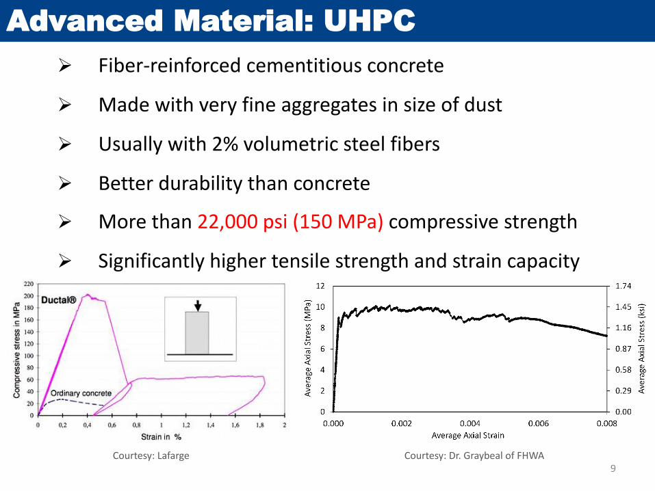
Advanced Material: UHPC
Fiber-reinforced cementitious concrete
Made with very fine aggregates in size of dust
Usually with 2% volumetric steel fibers
Better durability than concrete
More than 22,000 psi (150 MPa) compressive strength
Significantly higher tensile strength and strain capacity
Courtesy: Dr. Graybeal of FHWA9
Courtesy: Lafarge
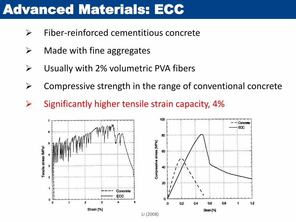
Advanced Materials: ECC
Fiber-reinforced cementitious concrete
Made with fine aggregates
Usually with 2% volumetric PVA fibers
Compressive strength in the range of conventional concrete
Significantly higher tensile strain capacity, 4%
Li (2008)
Column Damage
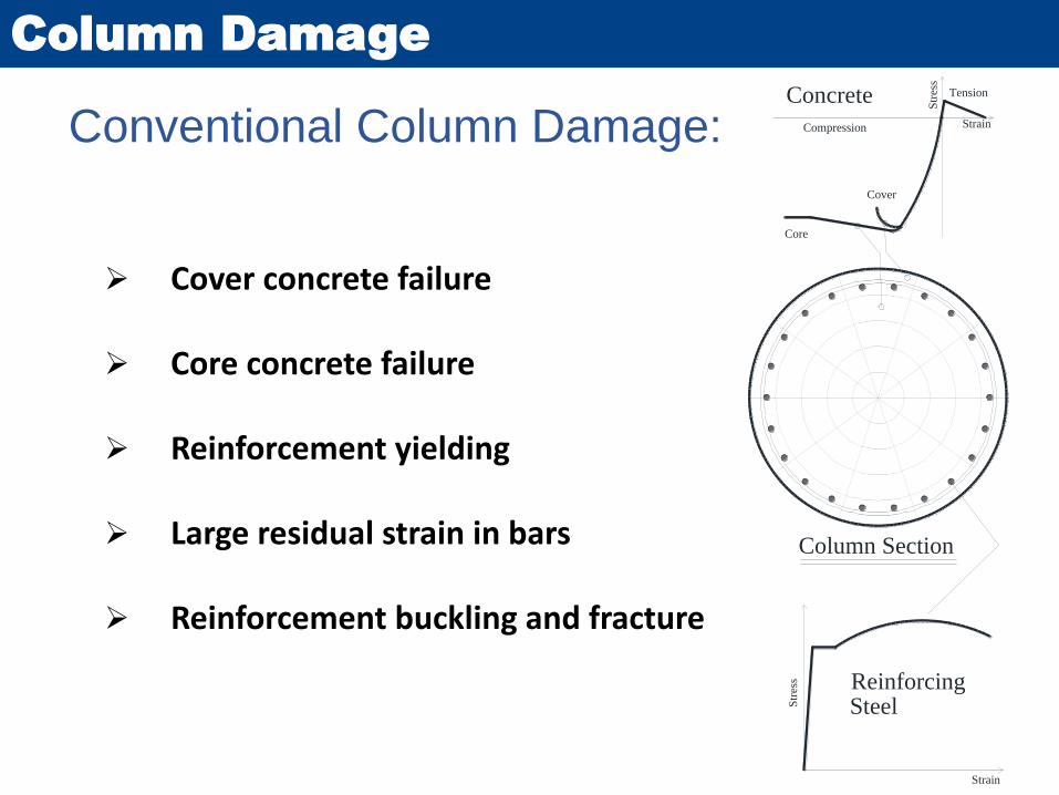
Conventional Column Damage:
Cover concrete failure
Core concrete failure
Reinforcement yielding
Large residual strain in bars
Reinforcement buckling and fracture
Str
ess
Strain
Compression
Concrete
Str
ess Reinforcing
Steel
Cover
Strain
Tension
Core
Column Section
UHPC-Filled Duct Connections
Emulative Connection
12

Grouted Duct Connections
Column to Cap Beam Connection
Column to Footing Connection
Extended ColumnReinforcing Bar
PrecastColumn
Cap BeamGrouted Duct
Column Section A-A Column Section B-B
A A
B B
Column Section A-A
Extended
Column
Bars
PrecastColumn
Footing
Grouted
Duct
A A
B B
Section B-B
Grouted
Duct
Normal grout as duct filler
We proposed UHPC as duct filler to connect precast columns to shallow cap beams and footings
13
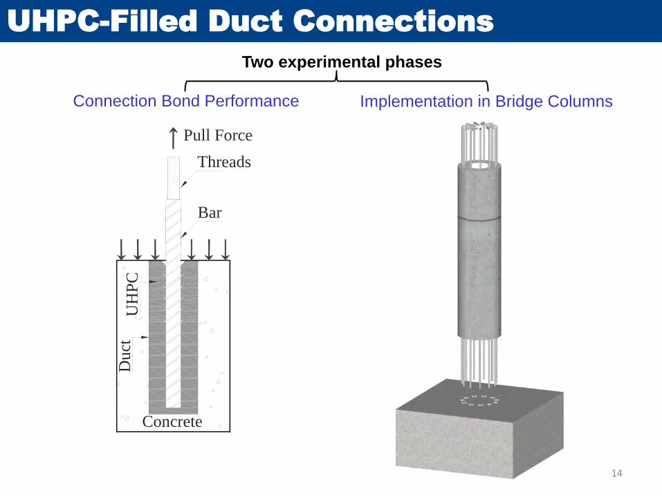
UHPC-Filled Duct Connections
Connection Bond Performance
Two experimental phases
Implementation in Bridge Columns
Concrete
Du
ct
Bar
UH
PC
Threads
Pull Force
14
UHPC-Filled Duct Connections
Concrete
Duct
Bar
UH
PC
Threads
Pull Force
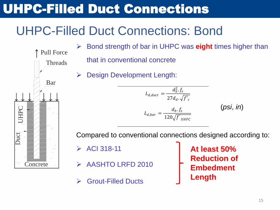
UHPC-Filled Duct Connections: Bond Bond strength of bar in UHPC was eight times higher than
that in conventional concrete
Design Development Length:
Compared to conventional connections designed according to:
ACI 318-11
AASHTO LRFD 2010
Grout-Filled Ducts
At least 50%
Reduction of
Embedment
Length
Ld = max (Ld,duct, Ld,bar) (2-13)
US Customary Unit SI Unit
𝐿𝑑 ,𝑑𝑢𝑐𝑡 =𝑑𝑏
2 .𝑓𝑠
27𝑑𝑑 . 𝑓′𝑐
𝐿𝑑 ,𝑑𝑢𝑐𝑡 =𝑑𝑏
2 . 𝑓𝑠
2.24𝑑𝑑 . 𝑓′𝑐
(2-14)
𝐿𝑑 ,𝑏𝑎𝑟 =𝑑𝑏 .𝑓𝑠
120 𝑓 ′ 𝑈𝐻𝑃𝐶
𝐿𝑑 ,𝑏𝑎𝑟 =𝑑𝑏 . 𝑓𝑠
9.96 𝑓 ′ 𝑈𝐻𝑃𝐶
(2-15)
(psi, in)
15
UHPC-Filled Duct Connections
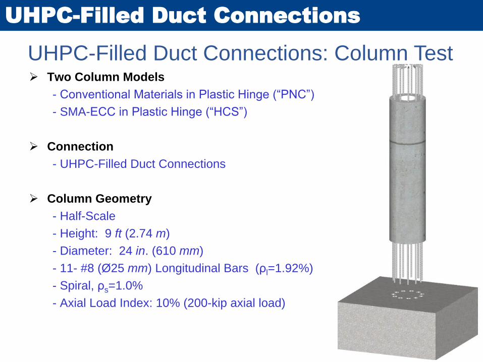
UHPC-Filled Duct Connections: Column Test Two Column Models
- Conventional Materials in Plastic Hinge (“PNC”)
- SMA-ECC in Plastic Hinge (“HCS”)
Connection
- UHPC-Filled Duct Connections
Column Geometry
- Half-Scale
- Height: 9 ft (2.74 m)
- Diameter: 24 in. (610 mm)
- 11- #8 (Ø25 mm) Longitudinal Bars (ρl=1.92%)
- Spiral, ρs=1.0%
- Axial Load Index: 10% (200-kip axial load)
16
UHPC-Filled Duct Connections
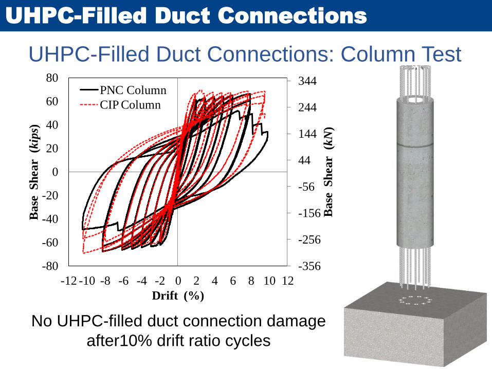
UHPC-Filled Duct Connections: Column Test
-356
-256
-156
-56
44
144
244
344
-80
-60
-40
-20
0
20
40
60
80
-12 -10 -8 -6 -4 -2 0 2 4 6 8 10 12
Ba
se S
hea
r
(kN
)
Ba
se S
hea
r
(kip
s)
Drift (%)
PNC Column
CIP Column
No UHPC-filled duct connection damage
after10% drift ratio cycles 17
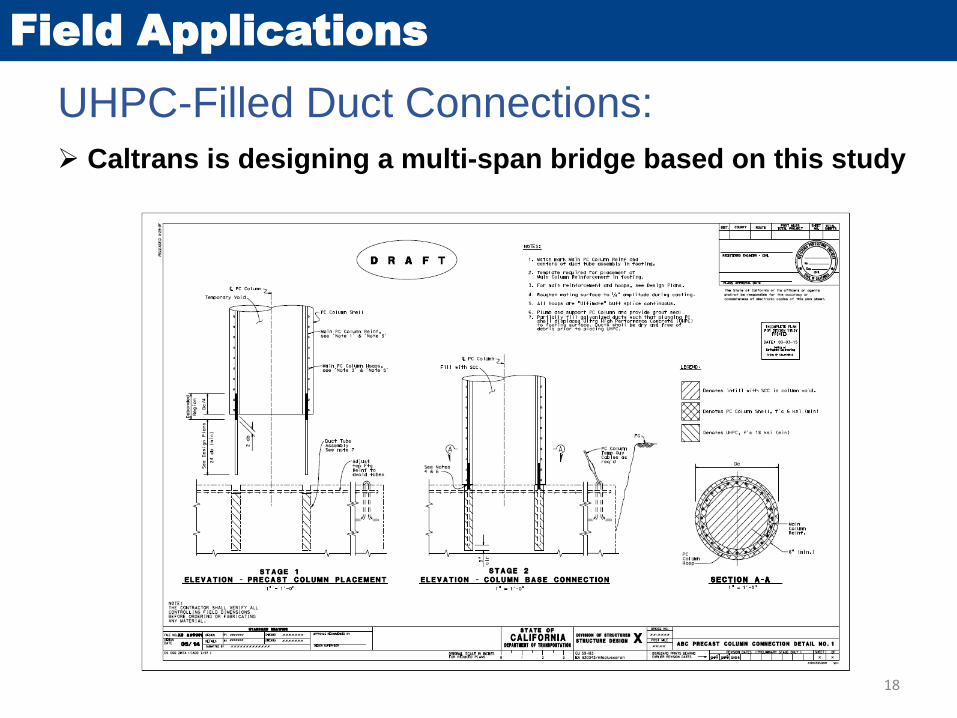
Field Applications
Caltrans is designing a multi-span bridge based on this study
18
UHPC-Filled Duct Connections:

Precast SMA-ECC Column
Improved Seismic Performance
19
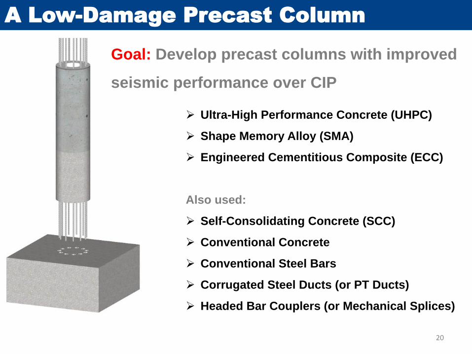
A Low-Damage Precast Column
Goal: Develop precast columns with improved
seismic performance over CIP
Ultra-High Performance Concrete (UHPC)
Shape Memory Alloy (SMA)
Engineered Cementitious Composite (ECC)
Also used:
Self-Consolidating Concrete (SCC)
Conventional Concrete
Conventional Steel Bars
Corrugated Steel Ducts (or PT Ducts)
Headed Bar Couplers (or Mechanical Splices)
20

Low-Damage Precast Column
21
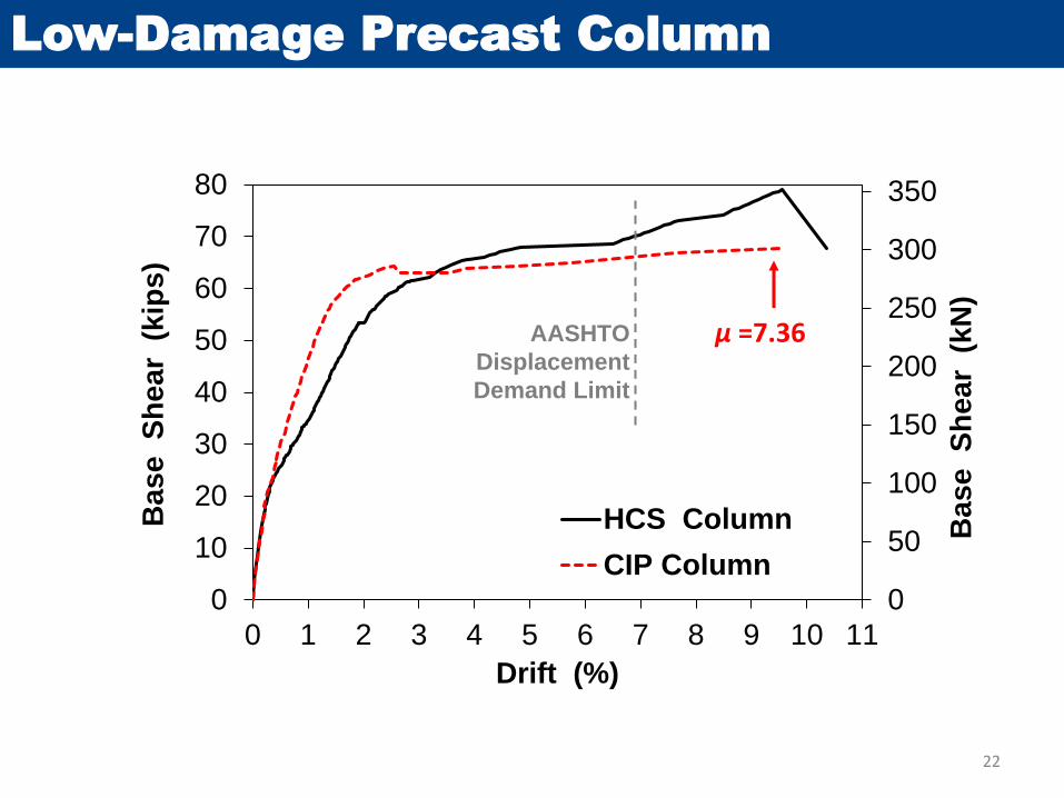
Low-Damage Precast Column
0
50
100
150
200
250
300
350
0
10
20
30
40
50
60
70
80
0 1 2 3 4 5 6 7 8 9 10 11
Base S
hear
(kN
)
Base S
hear
(kip
s)
Drift (%)
HCS Column
CIP Column
AASHTO
Displacement
Demand Limit
μ =7.36
22
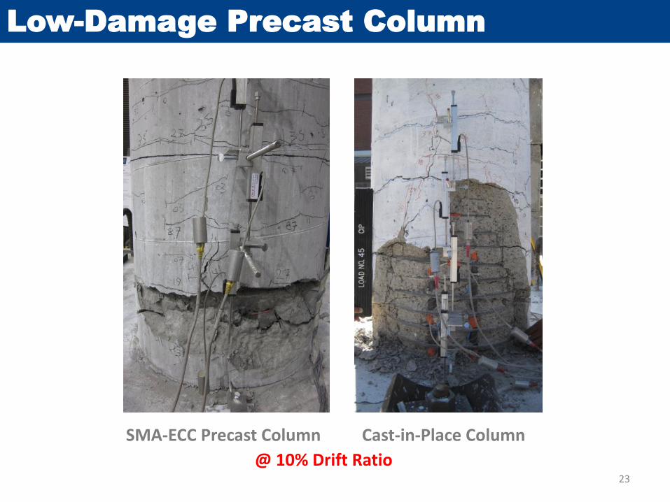
Low-Damage Precast Column
SMA-ECC Precast Column
@ 10% Drift Ratio
Cast-in-Place Column
23

Low-Damage Precast Column
79% Lower Residual Displacements
0
1
2
3
4
5
6
7
8
0 1 2 3 4 5 6 7 8 9 10 11
Resid
ual D
rift
(%
)
Peak Drift (%)
HCS Column
CIP Column
After 10% drift cycle24
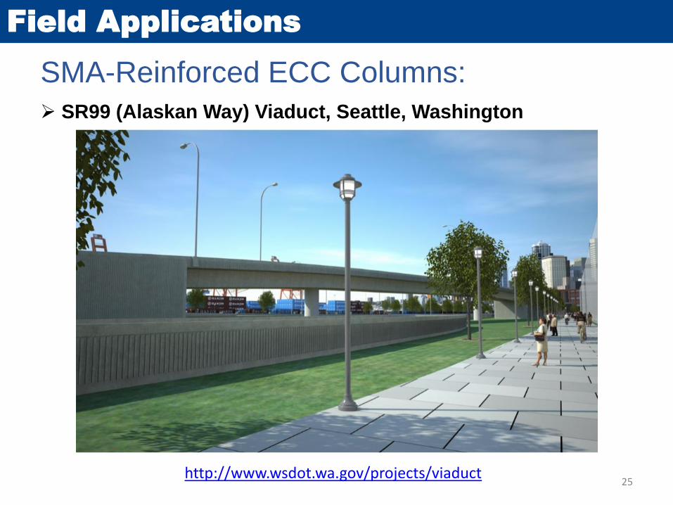
Field Applications
SR99 (Alaskan Way) Viaduct, Seattle, Washington
25
SMA-Reinforced ECC Columns:
http://www.wsdot.wa.gov/projects/viaduct
Mechanical Bar Splice Connections
26

Bar Coupler Connections
Mechanical Bar Couplers:
Headed Bar Coupler[hrc-usa.com]
Threaded Bar Coupler[erico.com]
Grouted Sleeve Coupler
Bar Grip Coupler Shear Screw Coupler[barsplice.com]
[splicesleeve.com]
[daytonsuperior.com]
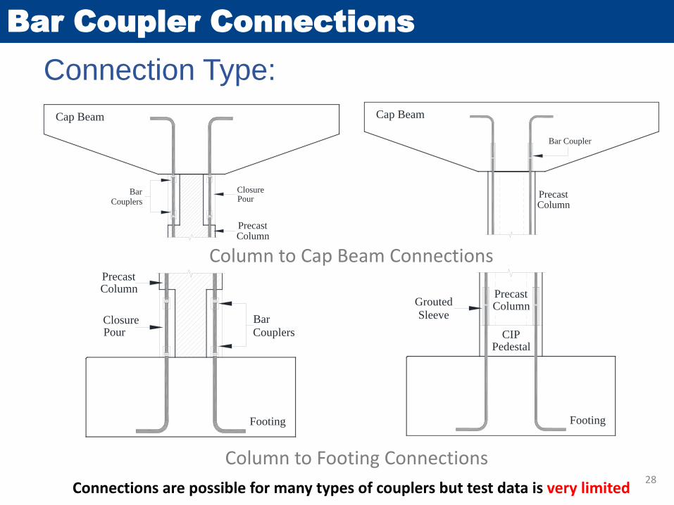
Bar Coupler Connections
Column to Cap Beam Connections
Connection Type:
Column to Footing Connections
PrecastColumn
Cap Beam
Bar Coupler
Connections are possible for many types of couplers but test data is very limited
PrecastColumn
Footing
Grouted
Sleeve
CIPPedestal
Bar
Couplers
PrecastColumn
Cap Beam
ClosurePour
Footing
PrecastColumn
Bar
CouplersClosurePour
28
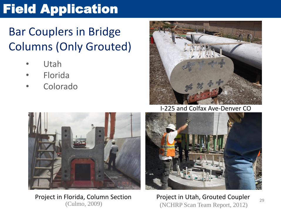
Bar Couplers in Bridge Columns (Only Grouted)
Field Application
• Utah• Florida• Colorado
Project in Florida, Column Section Project in Utah, Grouted Coupler(Culmo, 2009) (NCHRP Scan Team Report, 2012)
I-225 and Colfax Ave-Denver CO
29
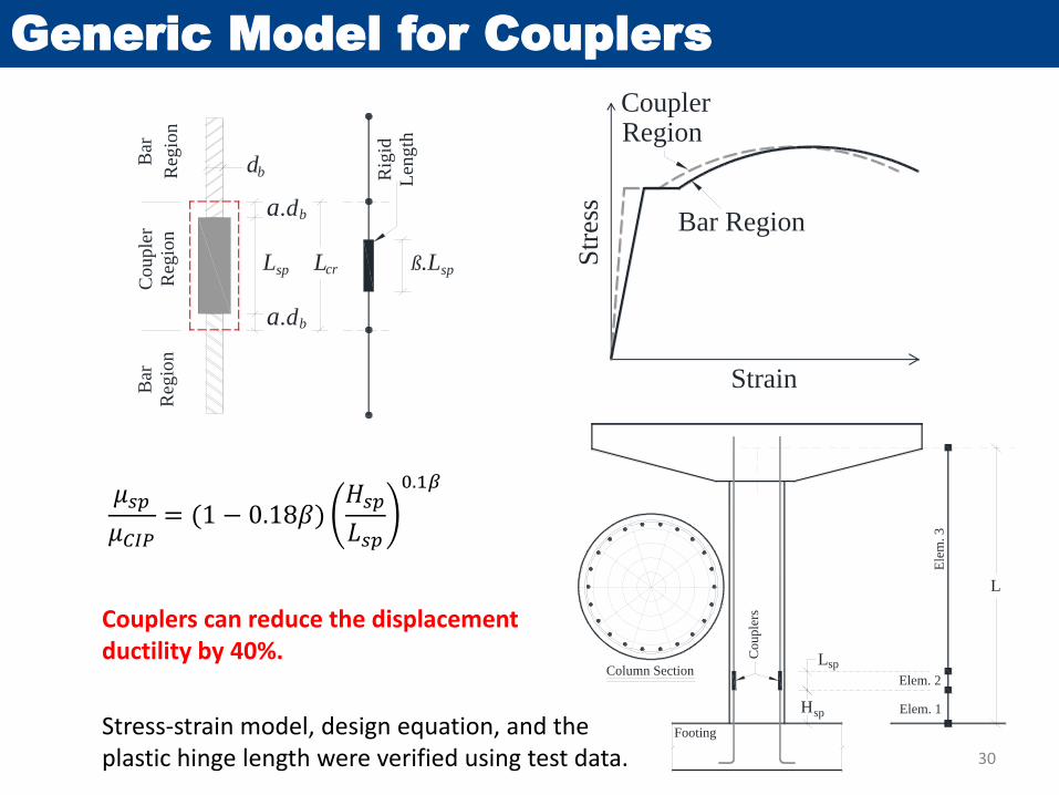
Generic Model for Couplers
30
Cou
ple
r
Reg
ion
Lsp
db
a.db
Bar
Reg
ion
a.db
ß.Lsp
Bar
Reg
ion
Rig
id
Len
gth
Lcr
Str
ess
Strain
Bar Region
CouplerRegion
Column Section
Hsp
Lsp
Elem. 1
Elem. 2
Ele
m.
3
L
Footing
Co
up
lers
𝜇𝑠𝑝
𝜇𝐶𝐼𝑃= (1 − 0.18𝛽)
𝐻𝑠𝑝
𝐿𝑠𝑝
0.1𝛽
Stress-strain model, design equation, and the plastic hinge length were verified using test data.
Couplers can reduce the displacement ductility by 40%.
Cap Beam Pocket Connections
Emulative Behavior
31
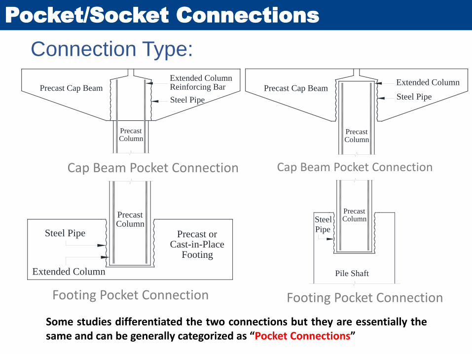
Cap Beam Pocket Connection
Pocket/Socket Connections
Extended ColumnReinforcing Bar
PrecastColumn
Precast Cap Beam
Steel Pipe
Extended Column
PrecastColumn
Precast Cap BeamSteel Pipe
Cap Beam Pocket Connection
Connection Type:
Footing Pocket Connection Footing Pocket Connection
Some studies differentiated the two connections but they are essentially thesame and can be generally categorized as “Pocket Connections”
Precast orCast-in-Place
Footing
Extended Column
Steel Pipe
PrecastColumn
PrecastColumn
Pile Shaft
Steel
Pipe
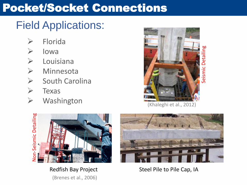
Field Applications:
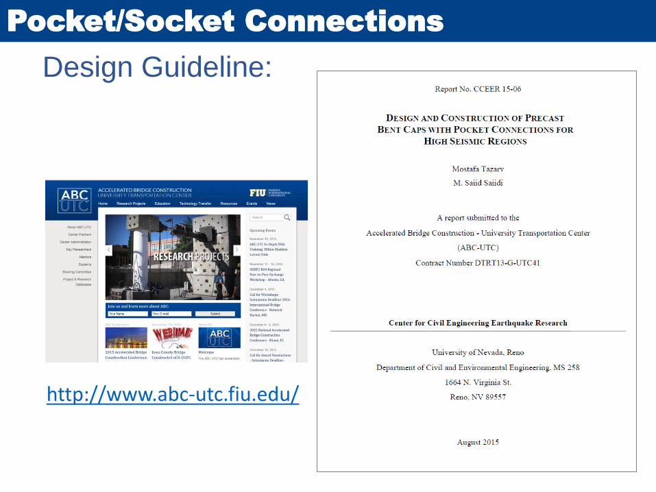
Pocket/Socket Connections
Florida Iowa Louisiana Minnesota South Carolina Texas Washington
Redfish Bay Project Steel Pile to Pile Cap, IA
(Brenes et al., 2006)
(Khaleghi et al., 2012)
No
n-S
eism
ic D
etai
ling
Seis
mic
Det
ailin
g
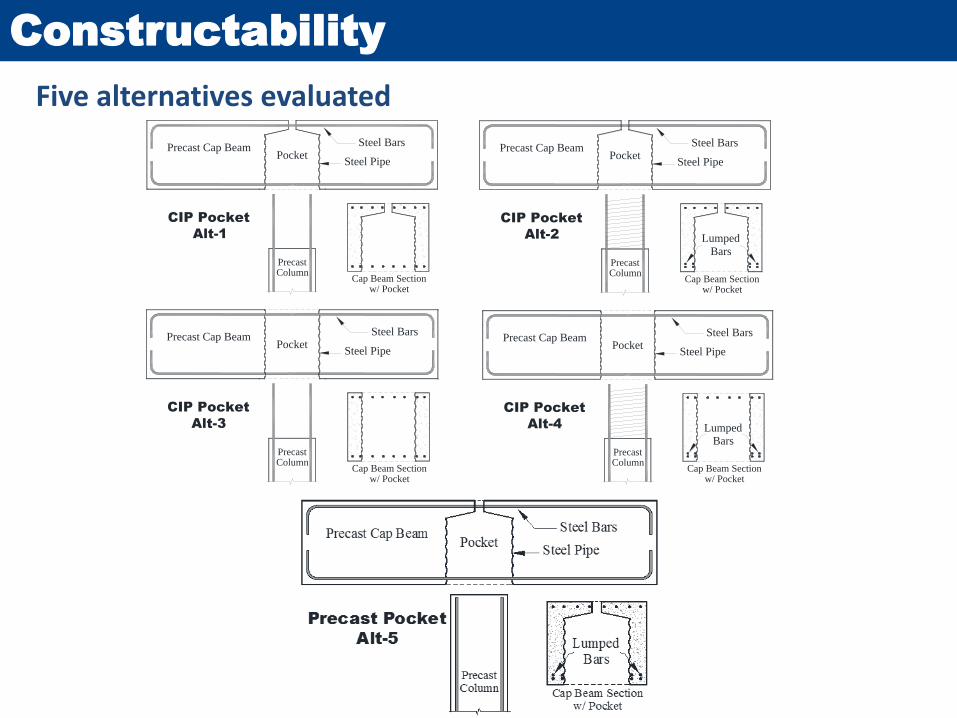
Constructability
Five alternatives evaluated
(a) Cast-in-Place Pocket Connections
PrecastColumn
Precast Cap Beam
Steel Pipe
CIP Pocket
Alt-1
Steel Bars
Cap Beam Sectionw/ Pocket
PrecastColumn
Precast Cap Beam
Steel Pipe
Steel Bars
Cap Beam Sectionw/ Pocket
CIP Pocket
Alt-2 Lumped
Bars
Steel Bars
Cap Beam Sectionw/ Pocket
CIP Pocket
Alt-3
PrecastColumn
Precast Cap Beam
Steel Pipe
PrecastColumn
Precast Cap Beam
Steel Pipe
Steel Bars
Cap Beam Sectionw/ Pocket
CIP Pocket
Alt-4 Lumped
Bars

Design Guidelines and Examples
35
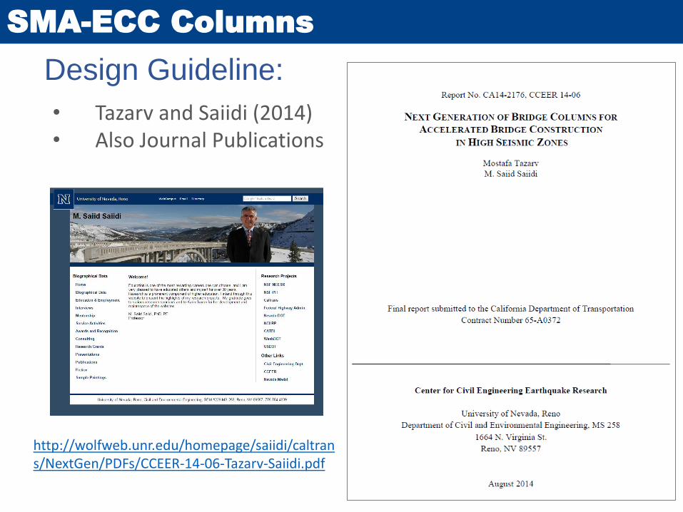
Design Guideline:
SMA-ECC Columns
• Tazarv and Saiidi (2014)• Also Journal Publications
http://wolfweb.unr.edu/homepage/saiidi/caltrans/NextGen/PDFs/CCEER-14-06-Tazarv-Saiidi.pdf
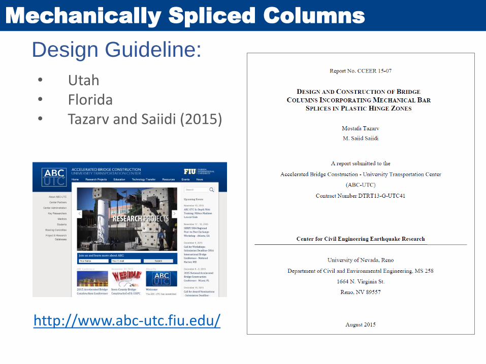
Design Guideline:
Mechanically Spliced Columns
http://www.abc-utc.fiu.edu/
• Utah• Florida• Tazarv and Saiidi (2015)
Conclusions
Advanced materials can be used to
build longer-lasting bridges faster
with continuous functionality even
after severe earthquakes
39

Questions?
40
Mostafa TazarvAssistant Professor
Department of Civil and Environmental Engineering
South Dakota State University (SDSU)
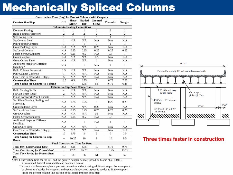
Mechanically Spliced Columns
Construction Time (Day) for Precast Columns with Couplers
Construction Step CIP Shear
Screw
Headed
Bar
Grouted
Sleeve Threaded Swaged
Column-to-Footing Connections
Excavate Footing 1 1 1 1 1 1
Build Footing Formwork 2 2 2 2 2 2
Set Footing Rebar 1 1 1 1 1 1
Set Column Steel 1 N/A N/A N/A N/A N/A
Pour Footing Concrete 1 1 1 1 1 1
Grout Bedding Layer N/A N/A N/A 0.25 N/A N/A
Set/Level Column N/A 0.25 0.25 0.25 0.25 0.25
Fasten Screws/Couplers N/A 0.25 0.5 N/A 0.5 1
Grout Couplers N/A N/A N/A 0.5 N/A N/A
Grout Curing Time N/A N/A N/A 1 N/A N/A
Additional Steps for Different
Detailing* N/A 1 1 N/A 1 1
Build Column Formwork 1.5 N/A N/A N/A N/A N/A
Pour Column Concrete 1 N/A N/A N/A N/A N/A
Cure Time to 80% (Min 5 Days) 5 N/A N/A N/A N/A N/A
Construction Time 13.5 6.5 6.75 7 6.75 7.25
Time Saving for Column-to-Footing -- 7 6.75 6.5 6.75 6.25
Column-to-Cap Beam Connections
Build Shoring/Soffit 4 N/A N/A N/A N/A N/A
Set Cap Beam Rebar 2 N/A N/A N/A N/A N/A
Finish Formwork/Pour Concrete 1 N/A N/A N/A N/A N/A
Set Shims/Shoring, Sealing, and
Surveying N/A 0.25 0.25 1 0.25 0.25
Grout Bedding Layer N/A N/A N/A 0.25 N/A N/A
Set/Level Cap Beam N/A 0.25 0.25 0.25 0.25 0.25
Grout Couplers N/A N/A N/A 0.5 N/A N/A
Fasten Screws/Couplers N/A 0.25 0.5 N/A 0.5 1
Additional Steps for Different
Detailing* N/A 1 1 N/A 1 1
Grout Cure Time N/A N/A N/A 1 N/A N/A
Cure Time to 80% (Min 5 Days) 5 N/A N/A N/A N/A N/A
Construction Time 12 1.75 2 3 2 2.5
Time Saving for Column-to-Cap
Beam -- 10.25 10 9 10 9.5
Total Construction Time for Bent
Total Bent Construction Time 25.5 8.25 8.75 10 8.75 9.75
Total Time Saving for Precast Bent -- 17.25 16.75 15.5 16.75 15.75
Total Time Saving for Precast Bent
(%) -- 68 66 61 66 62
Note: Construction time for the CIP and the grouted coupler bent are based on Marsh et al. (2011).
It is assumed that columns and the cap beam are precast.
* It is not possible to complete a precast connection without taking additional steps. For example, to
be able to use headed bar couplers in the plastic hinge area, a space is needed to fit the couplers
inside the precast column thus casting of this space imposes extra step.
Three times faster in construction
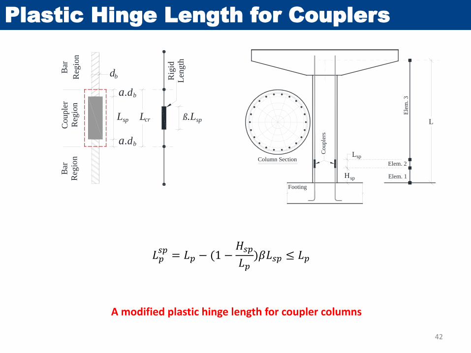
Plastic Hinge Length for Couplers
42
Cou
ple
r
Reg
ion
Lsp
db
a.db
Bar
Reg
ion
a.db
ß.Lsp
Bar
Reg
ion
Rig
id
Len
gth
Lcr
Column Section
Hsp
Lsp
Elem. 1
Elem. 2
Ele
m.
3
L
Footing
Co
up
lers
A modified plastic hinge length for coupler columns
𝐿𝑝𝑠𝑝= 𝐿𝑝 − (1 −
𝐻𝑠𝑝
𝐿𝑝)𝛽𝐿𝑠𝑝 ≤ 𝐿𝑝
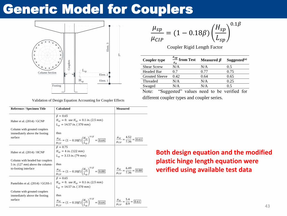
Generic Model for Couplers
43
Column Section
Hsp
Lsp
Elem. 1
Elem. 2
Ele
m.
3
L
Footing
Co
up
lers
𝜇𝑠𝑝
𝜇𝐶𝐼𝑃= (1 − 0.18𝛽)
𝐻𝑠𝑝
𝐿𝑠𝑝
0.1𝛽
Coupler Rigid Length Factor 1
Coupler type 𝜺𝒔𝒑
𝜺𝒔 from Test Measured 𝜷 Suggested(a)
Shear Screw N/A N/A 0.5
Headed Bar 0.7 0.77 0.75
Grouted Sleeve 0.42 0.64 0.65
Threaded N/A N/A 0.25
Swaged N/A N/A 0.5
Note: “Suggested” values need to be verified for 2
different coupler types and coupler series. 3 Validation of Design Equation Accounting for Coupler Effects 1
Reference / Specimen Title Calculated Measured
Haber et al. (2014) / GCNP
Column with grouted couplers
immediately above the footing
surface
𝛽 = 0.65
𝐻𝑠𝑝 = 0. use 𝐻𝑠𝑝 = 0.1 𝑖𝑛. (2.5 𝑚𝑚)
𝐿𝑠𝑝 = 14.57 𝑖𝑛. ( 370 𝑚𝑚)
thus
𝜇𝑠𝑝
𝜇𝐶𝐼𝑃= (1 − 0.18𝛽)
𝐻𝑠𝑝
𝐿𝑠𝑝
0.1𝛽
= 0.64
𝜇𝑠𝑝
𝜇𝐶𝐼𝑃=
4.52
7.36= 0.61
Haber et al. (2014) / HCNP
Column with headed bar couplers
5 in. (127 mm) above the column-
to-footing interface
𝛽 = 0.75
𝐻𝑠𝑝 = 4 𝑖𝑛. (122 𝑚𝑚)
𝐿𝑠𝑝 = 3.13 𝑖𝑛. (79 𝑚𝑚)
thus
𝜇𝑠𝑝
𝜇𝐶𝐼𝑃= (1 − 0.18𝛽)
𝐻𝑠𝑝
𝐿𝑠𝑝
0.1𝛽
= 0.88
𝜇𝑠𝑝
𝜇𝐶𝐼𝑃=
6.49
7.36= 0.88
Pantelides et al. (2014) / GGSS-1
Column with grouted couplers
immediately above the footing
surface
𝛽 = 0.65
𝐻𝑠𝑝 = 0. use 𝐻𝑠𝑝 = 0.1 𝑖𝑛. (2.5 𝑚𝑚)
𝐿𝑠𝑝 = 14.57 𝑖𝑛. ( 370 𝑚𝑚)
thus
𝜇𝑠𝑝
𝜇𝐶𝐼𝑃= (1 − 0.18𝛽)
𝐻𝑠𝑝
𝐿𝑠𝑝
0.1𝛽
= 0.64
𝜇𝑠𝑝
𝜇𝐶𝐼𝑃=
5.4
8.9= 0.61
2
Both design equation and the modified plastic hinge length equation were verified using available test data
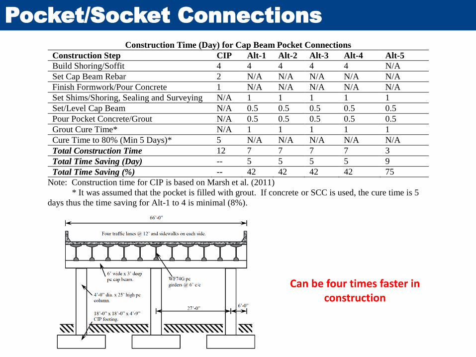
Pocket/Socket Connections
Construction Time (Day) for Cap Beam Pocket Connections
Construction Step CIP Alt-1 Alt-2 Alt-3 Alt-4 Alt-5
Build Shoring/Soffit 4 4 4 4 4 N/A
Set Cap Beam Rebar 2 N/A N/A N/A N/A N/A
Finish Formwork/Pour Concrete 1 N/A N/A N/A N/A N/A
Set Shims/Shoring, Sealing and Surveying N/A 1 1 1 1 1
Set/Level Cap Beam N/A 0.5 0.5 0.5 0.5 0.5
Pour Pocket Concrete/Grout N/A 0.5 0.5 0.5 0.5 0.5
Grout Cure Time* N/A 1 1 1 1 1
Cure Time to 80% (Min 5 Days)* 5 N/A N/A N/A N/A N/A
Total Construction Time 12 7 7 7 7 3
Total Time Saving (Day) -- 5 5 5 5 9
Total Time Saving (%) -- 42 42 42 42 75
Note: Construction time for CIP is based on Marsh et al. (2011)
* It was assumed that the pocket is filled with grout. If concrete or SCC is used, the cure time is 5
days thus the time saving for Alt-1 to 4 is minimal (8%).
Can be four times faster in construction
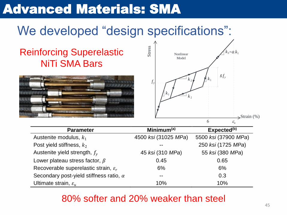
Advanced Materials: SMA
We developed “design specifications”:
Strain (%)
Str
ess
k1
k 2fy
ß.f y
k3Nonlinear
Model
u
k 2
k1
=a.k1
Parameter Minimum(a) Expected(b)
Austenite modulus, 𝑘1 4500 ksi (31025 MPa) 5500 ksi (37900 MPa)
Post yield stiffness, 𝑘2 -- 250 ksi (1725 MPa)
Austenite yield strength, 𝑓𝑦 45 ksi (310 MPa) 55 ksi (380 MPa)
Lower plateau stress factor, 𝛽 0.45 0.65
Recoverable superelastic strain, 𝜀𝑟 6% 6%
Secondary post-yield stiffness ratio, 𝛼 -- 0.3
Ultimate strain, 𝜀𝑢 10% 10%
Reinforcing Superelastic
NiTi SMA Bars
80% softer and 20% weaker than steel45
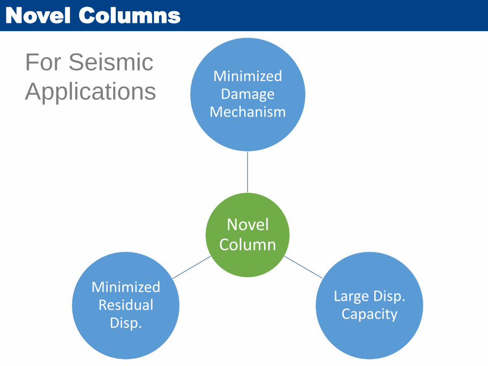
Novel Columns
Novel Column
Minimized Damage
Mechanism
Large Disp. Capacity
Minimized Residual
Disp.
For Seismic
Applications