application notes for configuring spectralink 84-series sip
TRANSCRIPT
KP; Reviewed:
SPOC 12/10/2014
Solution & Interoperability Test Lab Application Notes
©2014 Avaya Inc. All Rights Reserved.
1 of 40
8400-CS1K76
Avaya Solution & Interoperability Test Lab
Application Notes for Configuring Spectralink 84-Series SIP
Telephone Version 4.7.0 with Avaya Communication Server
1000 Release 7.6 - Issue 1.0
Abstract
These Application Notes describe a solution comprised of Avaya Communication Server 1000
SIP Line Release 7.6 and Spectralink 84-Series SIP telephone. During the compliance testing,
the Spectralink 8400 was able to register as a SIP client endpoint with the Communication
Server 1000 SIP Line gateway. The Spectralink 8400 telephone was able to place and receive
calls from the Communication Server 1000 Release 7.6 non-SIP and SIP Line clients. The
compliance tests focused on basic telephony features.
Readers should pay attention to section 2, in particular the scope of testing as outlined in
Section 2.1 as well as the observations noted in Section 2.2, to ensure that their own use cases
are adequately covered by this scope and results.
Information in these Application Notes has been obtained through DevConnect compliance
testing and additional technical discussions. Testing was conducted via the DevConnect
Program at the Avaya Solution and Interoperability Test Lab.
KP; Reviewed:
SPOC 12/10/2014
Solution & Interoperability Test Lab Application Notes
©2014 Avaya Inc. All Rights Reserved.
2 of 40
8400-CS1K76
1. Introduction These application notes provide detailed configurations of Avaya Communication Server 1000
SIP Line release 7.6 (hereafter referred to as CS 1000) and the model of Spectralink 84-Series
was used for the compliance test was 8440 (hereafter referred to as 8440). The Spectralink 84-
Series was tested with non-SIP and SIP clients using the CS 1000 SIP line release 7.6. All the
applicable telephony feature test cases of release 7.6 SIP line were executed on the 8440, where
applicable, to verify the interoperability with CS 1000.
These Application Notes assume that Avaya CS 1000 is already installed and basic configuration
steps have been performed. Only steps relevant to this compliance test will be described in this
document. For further details on configuration steps not covered in this document, consult the
documentation library mentioned in Section 9.
2. General Test Approach and Test Results The general test approach was to have the 8440 telephone register to the CS 1000 SIP line
gateway successfully. From the CS 1000 telephone clients/users, place a call to and from the
8440 telephone and to exercise other telephony features such as busy, hold, Dual Tone Multi
Frequency (DTMF), Message Waiting Indication (MWI) and codec negotiation.
DevConnect Compliance Testing is conducted jointly by Avaya and DevConnect members. The
jointly-defined test plan focuses on exercising APIs and/or standards-based interfaces pertinent
to the interoperability of the tested products and their functionalities. DevConnect Compliance
Testing is not intended to substitute full product performance or feature testing performed by
DevConnect members, nor is it to be construed as an endorsement by Avaya of the suitability or
completeness of a DevConnect member’s solution.
2.1. Interoperability Compliance Testing
The focus of this testing was to verify that the 8440 wireless telephone was able to interoperate
with the CS 1000 SIP line system. The following areas were tested:
Registration of the 8440 wireless telephone to the CS 1000 SIP Line Gateway.
Telephony features: Basic calls, conference, transfer, DTMF RFC2833 transmission,
voicemail with Message Waiting Indication notification, busy, hold, speed dial, group
call pickup, call waiting, ring again busy/no answer, multiple appearances Directory
Number.
PSTN calls over ISDN/PRI trunk.
Codec negotiation – G.711 and G.729.

KP; Reviewed:
SPOC 12/10/2014
Solution & Interoperability Test Lab Application Notes
©2014 Avaya Inc. All Rights Reserved.
3 of 40
8400-CS1K76
2.2. Test Results
The objectives outlined in Section 2.1 were verified. The following observations were made
during the compliance testing:
Avaya has not performed audio performance testing or reviewed the 8440 compliance to
required industry standards.
The 8440 telephones are treated by the CS 1000 as 3rd party SIP endpoints and use CS
1000 3rd party SIP licenses.
The Spectralink 8400 local forward busy feature which is set on the phone locally can be
enabled but it is not used. The server call forward busy feature of CS 1000 SIP Line will
take place before the local forward busy can be executed by the phone. For the call
forward busy, use the forward busy on the CS 1000 switch instead.
Transfer call performed on the 8440 failed if codec G.722 is used. It is recommended that
G.722 be disabled on the 8440 when using to with Avaya CS 1000.
With 3-way conference call on the 8440 by default set to 1 (Default) which is the
conference call will be not terminated when the host conference 8400 disconnects. This
will cause no audio for remaining parties in the conference call. To avoid this issue,
setting call.transferOnConferenceEnd to 0 in .cfg file, and the conference call will be
terminated when the host conference 8400 phone disconnects.
In an event of losing the wireless signal, an active call between 8400 phones or between
the 8400 and a desk phone causes the SIP Line trunk kept in busy until it is either
manually released in call server, or the handshake timer expires (the timer default setting
in the 8400 phones is about 8 minutes).
2.3. Support
Technical support on the Spectralink 84-Series telephone can be obtained through the following:
North America:
Phone: 1-800-775-5330
Email: [email protected]
Web: http://support.spectralink.com
EMEA:
Phone: +33 176774541
Email: [email protected]
Web: http://support.spectralink.com

KP; Reviewed:
SPOC 12/10/2014
Solution & Interoperability Test Lab Application Notes
©2014 Avaya Inc. All Rights Reserved.
4 of 40
8400-CS1K76
Reference Configuration
Figure 1 illustrates the test configuration used during the compliance testing between the Avaya
Communication Server 1000 and the Spectralink 8440. The 8440 phone registers to the CS 1000
SIP Line server by going through the Wi-Fi access point that connects to the lab network. Avaya
Aura® Session Manager was used for routing SIP calls between the CS 1000 A and CS 1000 B
for test cases off-net via SIP trunk. The PRI T1 trunk was configured to connect to PSTN for test
cases off-net via PRI T1 trunk.
Figure 1: Test Configuration Diagram

KP; Reviewed:
SPOC 12/10/2014
Solution & Interoperability Test Lab Application Notes
©2014 Avaya Inc. All Rights Reserved.
5 of 40
8400-CS1K76
3. Equipment and Software Validated The following equipment and software were used for the sample configuration provided:
Equipment/Software Release/Version
Avaya S8800 server running Avaya Aura®
Session Manager Server
6.3.7.0.637008
Avaya S8800 server running Avaya Aura®
System Manager Server
6.3.7 (Build No 6.3.0.8.5682-6.3.8.3204
Software Update Revision No:
6.3.7.7.2275)
Avaya S8800 server running Avaya Aura®
Messaging Server
6.3
Avaya Communication Server
1000E/CPPM
Avaya Communication Server Release 7.6
Q+ Deplist 1 (created: 2014-07-23) and
Service Pack 5 (Created: 2014-Jul-10)
Avaya IP SIP Phone 1140E 4.3
Avaya IP Unistim Phone 1165E 0x25C8J
Avaya IP Unistim Phone 2004 0604DCN
Spectralink 8440 4.7.0.2327
4. Configure Avaya Communication Server 1000 This section describes the steps to configure the Avaya CS 1000 SIP Line using CS 1000
Element Manager. A command line interface (CLI) option is available to provision the SIP Line
application on the CS 1000 system. For detailed information on how to configure and administer
the CS 1000 SIP Line, please refer to the Section 9 [1].
The following is a summary of tasks required for configuring the CS 1000 SIP Line:
Log in to Unified Communications Management (UCM) and Element Manager (EM).
Enable SIP Line Service and configure local SIP Domain.
Create SIP Line Telephony Node.
Create D-Channel for SIP Line.
Create an Application Module Link (AML).
Create a Value Added Server (VAS).
Create a Virtual Trunk Zone.
Create a SIP Line Route Data Block (RDB).
Create SIP Line Virtual Trunks.
Create a SIP Line Phone.

KP; Reviewed:
SPOC 12/10/2014
Solution & Interoperability Test Lab Application Notes
©2014 Avaya Inc. All Rights Reserved.
6 of 40
8400-CS1K76
4.1. Prerequisite
This document assumes that the CS 1000 SIP Line server has been:
- Installed with CS 1000 Release 7.6 Linux Base.
- Joined CS 1000 Release 7.6 Security Domain.
- Deployed with SIP Line Application.
The following packages need to be enabled in the key code. If any of these features have not
been enabled, please contact your Avaya account team or Avaya technical support at
http://www.avaya.com.
Package Mnemonic Package # Descriptions Package Type Applicable market
SIP_LINES 417 SIP Line Service
package
New package Global
FFC 139 Flexible Feature
Codes
Existing package Global
SIPL_AVAYA 415 Avaya SIP Line
package
Existing package Global
SIPL_3RDPARTY 416 Third-Party SIP Line
Package
Existing package Global
KP; Reviewed:
SPOC 12/10/2014
Solution & Interoperability Test Lab Application Notes
©2014 Avaya Inc. All Rights Reserved.
7 of 40
8400-CS1K76
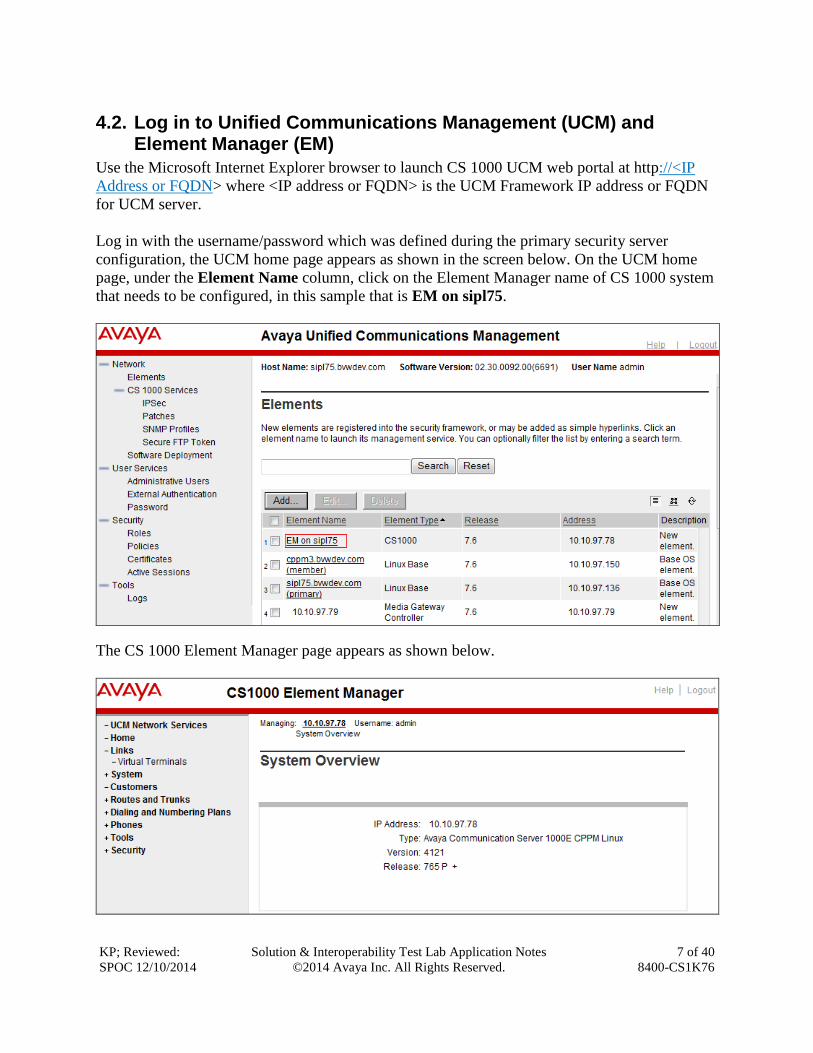
4.2. Log in to Unified Communications Management (UCM) and Element Manager (EM)
Use the Microsoft Internet Explorer browser to launch CS 1000 UCM web portal at http://<IP
Address or FQDN> where <IP address or FQDN> is the UCM Framework IP address or FQDN
for UCM server.
Log in with the username/password which was defined during the primary security server
configuration, the UCM home page appears as shown in the screen below. On the UCM home
page, under the Element Name column, click on the Element Manager name of CS 1000 system
that needs to be configured, in this sample that is EM on sipl75.
The CS 1000 Element Manager page appears as shown below.
KP; Reviewed:
SPOC 12/10/2014
Solution & Interoperability Test Lab Application Notes
©2014 Avaya Inc. All Rights Reserved.
8 of 40
8400-CS1K76
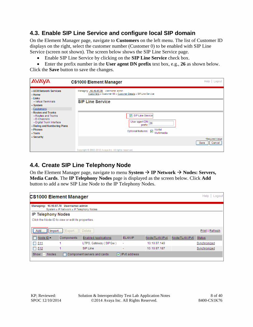
4.3. Enable SIP Line Service and configure local SIP domain
On the Element Manager page, navigate to Customers on the left menu. The list of Customer ID
displays on the right, select the customer number (Customer 0) to be enabled with SIP Line
Service (screen not shown). The screen below shows the SIP Line Service page.
Enable SIP Line Service by clicking on the SIP Line Service check box.
Enter the prefix number in the User agent DN prefix text box, e.g., 26 as shown below.
Click the Save button to save the changes.
4.4. Create SIP Line Telephony Node
On the Element Manager page, navigate to menu System IP Network Nodes: Servers,
Media Cards. The IP Telephony Nodes page is displayed as the screen below. Click Add
button to add a new SIP Line Node to the IP Telephony Nodes.
KP; Reviewed:
SPOC 12/10/2014
Solution & Interoperability Test Lab Application Notes
©2014 Avaya Inc. All Rights Reserved.
9 of 40
8400-CS1K76
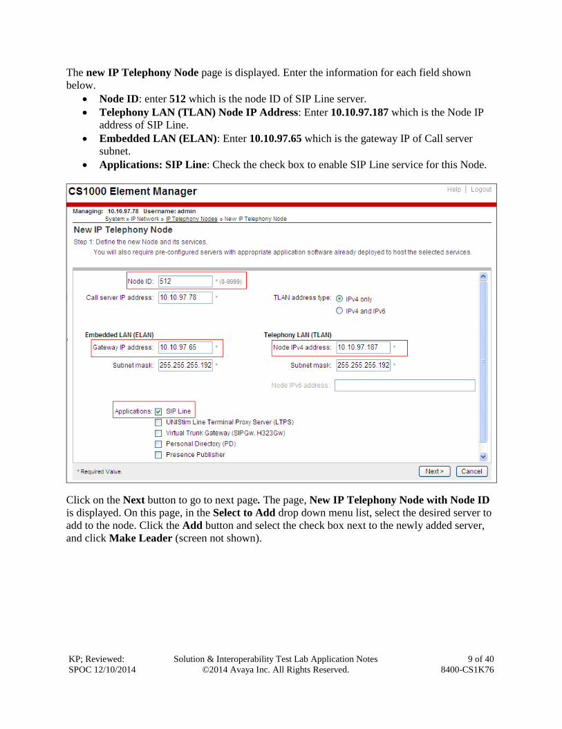
The new IP Telephony Node page is displayed. Enter the information for each field shown
below.
Node ID: enter 512 which is the node ID of SIP Line server.
Telephony LAN (TLAN) Node IP Address: Enter 10.10.97.187 which is the Node IP
address of SIP Line.
Embedded LAN (ELAN): Enter 10.10.97.65 which is the gateway IP of Call server
subnet.
Applications: SIP Line: Check the check box to enable SIP Line service for this Node.
Click on the Next button to go to next page. The page, New IP Telephony Node with Node ID
is displayed. On this page, in the Select to Add drop down menu list, select the desired server to
add to the node. Click the Add button and select the check box next to the newly added server,
and click Make Leader (screen not shown).
KP; Reviewed:
SPOC 12/10/2014
Solution & Interoperability Test Lab Application Notes
©2014 Avaya Inc. All Rights Reserved.
10 of 40
8400-CS1K76
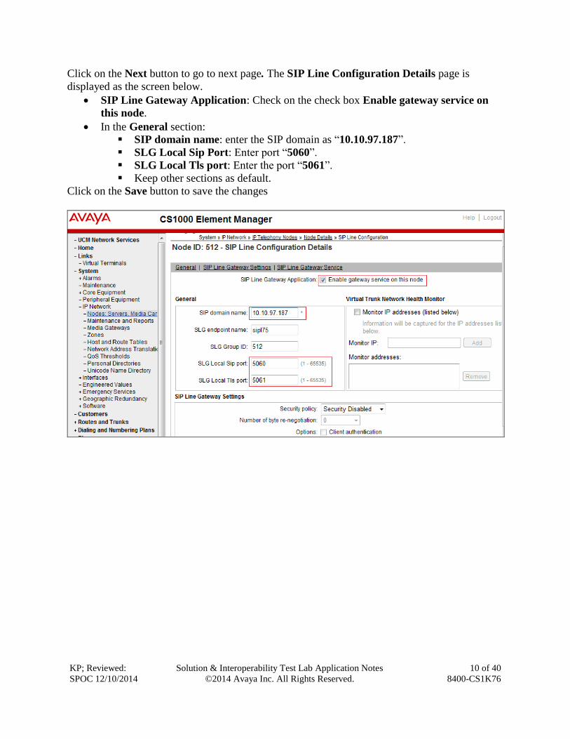
Click on the Next button to go to next page. The SIP Line Configuration Details page is
displayed as the screen below.
SIP Line Gateway Application: Check on the check box Enable gateway service on
this node.
In the General section:
SIP domain name: enter the SIP domain as “10.10.97.187”.
SLG Local Sip Port: Enter port “5060”.
SLG Local Tls port: Enter the port “5061”.
Keep other sections as default.
Click on the Save button to save the changes
KP; Reviewed:
SPOC 12/10/2014
Solution & Interoperability Test Lab Application Notes
©2014 Avaya Inc. All Rights Reserved.
11 of 40
8400-CS1K76
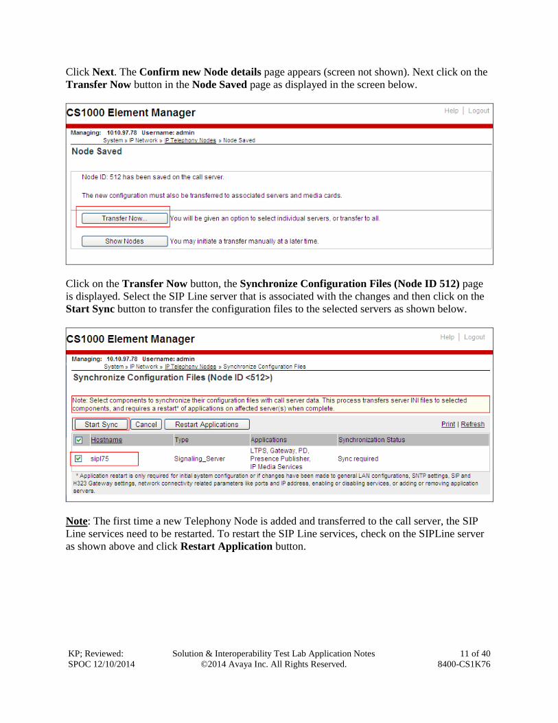
Click Next. The Confirm new Node details page appears (screen not shown). Next click on the
Transfer Now button in the Node Saved page as displayed in the screen below.
Click on the Transfer Now button, the Synchronize Configuration Files (Node ID 512) page
is displayed. Select the SIP Line server that is associated with the changes and then click on the
Start Sync button to transfer the configuration files to the selected servers as shown below.
Note: The first time a new Telephony Node is added and transferred to the call server, the SIP
Line services need to be restarted. To restart the SIP Line services, check on the SIPLine server
as shown above and click Restart Application button.

KP; Reviewed:
SPOC 12/10/2014
Solution & Interoperability Test Lab Application Notes
©2014 Avaya Inc. All Rights Reserved.
12 of 40
8400-CS1K76
4.5. Create a D-Channel for SIP Line
On the Element Manager page, navigate to Routes and Trunks D-Channels. The D-
Channels page is displayed on the right, under the Configuration section as shown below, enter
an available number in the Choose a D-Channel Number drop down menu, e.g., 3 and click on
the “to Add” button.

KP; Reviewed:
SPOC 12/10/2014
Solution & Interoperability Test Lab Application Notes
©2014 Avaya Inc. All Rights Reserved.
13 of 40
8400-CS1K76
The D-Channels 3 Property Configuration page is displayed. In the Basic Configuration
section:
D channel Card Type: Select D-Channel is over IP (DCIP).
Designator: Enter a descriptive name, e.g., “SIPLine”.
Interface type for D-channel: Select Meridian Meridian1 (SL1).
Leave the other fields in the section at default values.
Click on the Basic options (BSCOPT) link to expand this section. The Basic options
(BSCOPT) section is displayed as shown below. Click on Edit button to configure Remote
Capabilities (RCAP).
KP; Reviewed:
SPOC 12/10/2014
Solution & Interoperability Test Lab Application Notes
©2014 Avaya Inc. All Rights Reserved.
14 of 40
8400-CS1K76
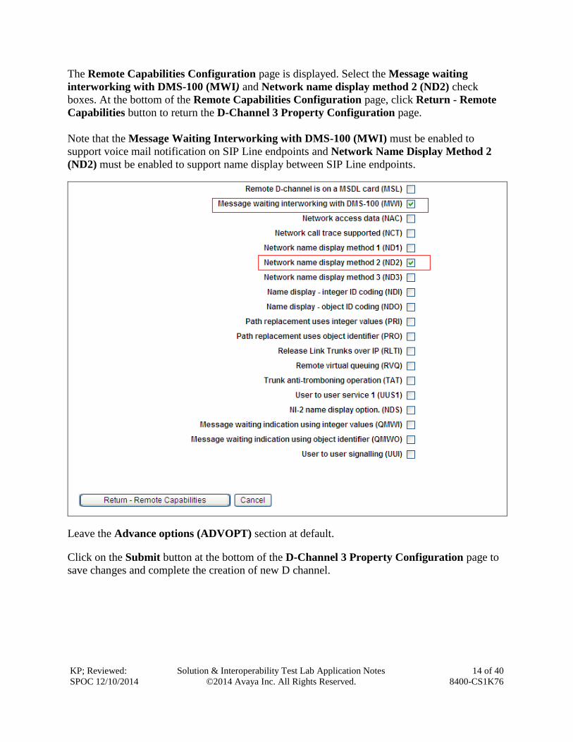
The Remote Capabilities Configuration page is displayed. Select the Message waiting
interworking with DMS-100 (MWI) and Network name display method 2 (ND2) check
boxes. At the bottom of the Remote Capabilities Configuration page, click Return - Remote
Capabilities button to return the D-Channel 3 Property Configuration page.
Note that the Message Waiting Interworking with DMS-100 (MWI) must be enabled to
support voice mail notification on SIP Line endpoints and Network Name Display Method 2
(ND2) must be enabled to support name display between SIP Line endpoints.
Leave the Advance options (ADVOPT) section at default.
Click on the Submit button at the bottom of the D-Channel 3 Property Configuration page to
save changes and complete the creation of new D channel.

KP; Reviewed:
SPOC 12/10/2014
Solution & Interoperability Test Lab Application Notes
©2014 Avaya Inc. All Rights Reserved.
15 of 40
8400-CS1K76
4.6. Create an Application Module Link (AML)
On the Element Manager page, navigate to System Interfaces Application Module Link.
The Application Module Link page is displayed on the right (screen not shown), click on the
Add button to add a new Application Module Link. The New Application Module Link page is
displayed as below.
Enter an AML port number in the Port number text box, e.g., 32 and a descriptive name, e.g.,
“SIPL” in the Description box. Note that The AML of SIP Line Service can use any port from
32 to 127. In this case, SIP Line Service is configured to use port 32. Click on the Save button to
complete the addition of the new AML link.

KP; Reviewed:
SPOC 12/10/2014
Solution & Interoperability Test Lab Application Notes
©2014 Avaya Inc. All Rights Reserved.
16 of 40
8400-CS1K76
4.7. Create a Value Added Server (VAS)
On the Element Manager home page, navigate to System Interfaces Value Added
Server. The Value Added Server page is displayed on the right, click on the Add button. The
Add Value Added Server page is displayed; select the link Ethernet LAN Link.
The Ethernet Link page is displayed as shown below. Enter a number in the Value added
server ID field, e.g., 32 and in the Ethernet LAN Link drop down list, select the AML number
of ELAN that was created in Section 5.6. Leave the other fields as default values and click on
the Save button to complete the addition of the new VAS.
KP; Reviewed:
SPOC 12/10/2014
Solution & Interoperability Test Lab Application Notes
©2014 Avaya Inc. All Rights Reserved.
17 of 40
8400-CS1K76
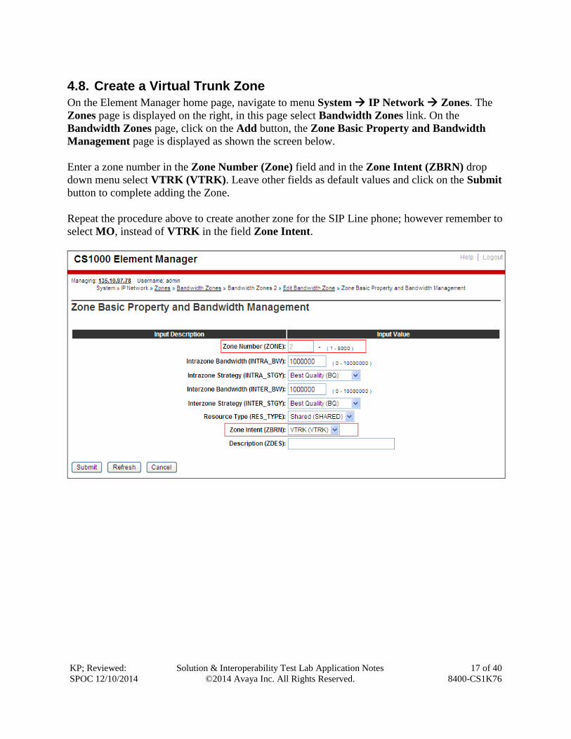
4.8. Create a Virtual Trunk Zone
On the Element Manager home page, navigate to menu System IP Network Zones. The
Zones page is displayed on the right, in this page select Bandwidth Zones link. On the
Bandwidth Zones page, click on the Add button, the Zone Basic Property and Bandwidth
Management page is displayed as shown the screen below.
Enter a zone number in the Zone Number (Zone) field and in the Zone Intent (ZBRN) drop
down menu select VTRK (VTRK). Leave other fields as default values and click on the Submit
button to complete adding the Zone.
Repeat the procedure above to create another zone for the SIP Line phone; however remember to
select MO, instead of VTRK in the field Zone Intent.
KP; Reviewed:
SPOC 12/10/2014
Solution & Interoperability Test Lab Application Notes
©2014 Avaya Inc. All Rights Reserved.
18 of 40
8400-CS1K76
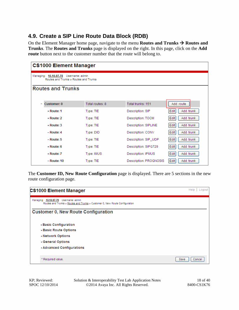
4.9. Create a SIP Line Route Data Block (RDB)
On the Element Manager home page, navigate to the menu Routes and Trunks Routes and
Trunks. The Routes and Trunks page is displayed on the right. In this page, click on the Add
route button next to the customer number that the route will belong to.
The Customer ID, New Route Configuration page is displayed. There are 5 sections in the new
route configuration page.

KP; Reviewed:
SPOC 12/10/2014
Solution & Interoperability Test Lab Application Notes
©2014 Avaya Inc. All Rights Reserved.
19 of 40
8400-CS1K76
Expand the Basic Configuration section, and enter values as shown in the two screens below.
Route Number (ROUT): Select an available number in the list, e.g., 8.
Designator field for trunk (DES): Enter a descriptive name, e.g., SIPL.
Trunk type (TKTP): Select TIE trunk data block (TIE).
Incoming and outgoing trunk (ICOG): Select Incoming and Outgoing (IAO).
Access code for trunk route (ACOD): Enter a number for ACOD, for example 8008.
Note that this number has to follow the dialing plan rule.
The route is for a virtual trunk route (VTRK): Check the checkbox.
Zone for codec selection and bandwidth management (ZONE): Enter 2 which is the
Virtual trunk zone number created in Section 5.8.
Node ID of signaling server of this route (NODE): Enter 512 which is the node ID of
the SIP Line configured in Section 5.4.
Protocol ID for the route (PCID): Select SIP Line (SIPL) in the list.
Integrated services digital network option (ISDN): Check the check box.

KP; Reviewed:
SPOC 12/10/2014
Solution & Interoperability Test Lab Application Notes
©2014 Avaya Inc. All Rights Reserved.
20 of 40
8400-CS1K76
Mode of operation (MODE): Select Route uses ISDN Signaling Link (ISLD).
D channel number (DCH): Enter 3 which is the D-channel number created in the
Section 5.5.
Interface type for route (IFC): Select Meridian M1 (SL1).
Network calling name allowed (NCNA): Check the check box.
Network call redirection (NCRD): Check the check box.
Trunk route optimization (TRO): Check the check box.
Channel type (CHTY): B-channel (BCH).
Trunk route optimization (TRO): Check the check box.
Call type for outgoing direct dialed TIE route (CTYP): Select Unknown Call type
(UKWN).
Calling Number dialing plan (CNDP): Select Coordinated dialing plan (CDP).
Leave default values for The Basic Route Options, Network Options, General Options, and
Advanced Configurations sections. Click the Submit button to complete the addition of new
route and save configuration.

KP; Reviewed:
SPOC 12/10/2014
Solution & Interoperability Test Lab Application Notes
©2014 Avaya Inc. All Rights Reserved.
21 of 40
8400-CS1K76
4.10. Create SIP Line Virtual Trunks
On the Element Manager home page, navigate to Routes and Trunks Routes and Trunks.
The Routes and Trunks page is displayed on the right, select the Add trunk button beside the
route 8 that was created in the Section 5.9 above to create new trunks.

KP; Reviewed:
SPOC 12/10/2014
Solution & Interoperability Test Lab Application Notes
©2014 Avaya Inc. All Rights Reserved.
22 of 40
8400-CS1K76
The Customer 0, Route 8, Trunk type TIE trunk data block page is displayed. Enter values
for fields as shown below:
Multiple trunk input numberEnter 32 to create 32 trunks.
Auto increment member number: Checked. The trunks are created incrementally.
Trunk data block: Select IP Trunk (IPTI).
Terminal Number: 100 0 8 0. Enter the first Terminal Number in a range of Terminal
number.
Designator field for trunk: Enter a descriptive name, e.g., “SIPL Trk”.
Member number: enter 97. This is the ID of the trunk, just enter the first ID for the first
trunk, next ID will be automatically created and incremented.
Start arrangement Incoming: Select Immediate (IMM).
Start arrangement Outgoing: Select Immediate (IMM).
Channel ID for this trunk: 97, this channel ID should be the same as the ID of Member
Number and it has to be a unique number in the same type of trunk.

KP; Reviewed:
SPOC 12/10/2014
Solution & Interoperability Test Lab Application Notes
©2014 Avaya Inc. All Rights Reserved.
23 of 40
8400-CS1K76
Click on the Class of Service button and assign following class of services as shown the screen
below:
Dial Pulse Select Digitone (DTN).
Media security: Select Media Security Never (MSNV).
Restriction level: Select Unrestricted (UNR).
Leave other class of services at default values and click on the Return Class of Service
button to return to the Trunk type TIE trunk data block page.
Leave the Advance Trunk Configurations section at default values and click on the Save
button to complete the addition of new virtual trunks for SIP Line.

KP; Reviewed:
SPOC 12/10/2014
Solution & Interoperability Test Lab Application Notes
©2014 Avaya Inc. All Rights Reserved.
24 of 40
8400-CS1K76
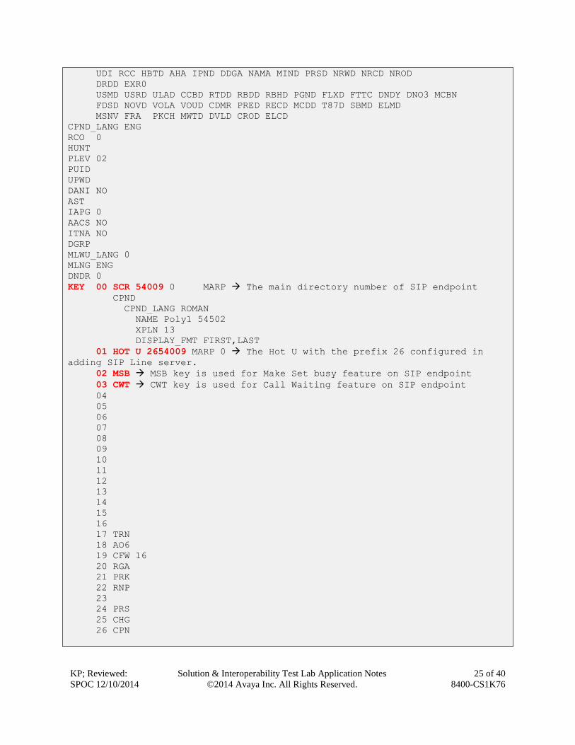
4.11. Create a SIP Line Phone
To create a SIP Line phone on the Call Server, log in as administrator using the command line
interface (CLI) and issue the overlay (LD) 11/20 as shown below.
The bold fields must be properly inputted as they are configured on the Call server, for other
fields hit enter to leave it at default values.
LD 20
Req prt
TYPE: uext
TN 104 0 0 2
DES SL8741
TN 104 0 00 02 Terminal number of Universal Extension of SIP Line phone
TYPE UEXT
CDEN 8D
CTYP XDLC
CUST 0
UXTY SIPL Type of UXTY is SIP Line
MCCL YES
SIPN 0
SIP3 1 3rd SIP endpoint is enabled
FMCL 0
TLSV 0
SIPU 54009 SIP user which is used in the SIP endpoint for registration
NDID 512 The node ID of SIP Line.
SUPR NO
UXID
NUID
CFG_ZONE 00001 Zone for SIP endpoint configured as MO
MRT
ERL
ECL 0
VSIT NO
FDN
TGAR 1
LDN NO
NCOS 0
SGRP 0
RNPG 0
SCI 0
XLST
SCPW 1234 The password used to register to SIP Line server
SFLT NO
CAC_MFC 0
CLS CTD FBA WTA LPR MTD FNA HTD TDD HFD CRPD Depend on feature cls enabled
MWA LMPN RMMD SMWD AAD IMD XHD IRD NID OLD VCE DRG1
POD SLKD CCSD SWD LND CNDA
CFTD SFD MRD DDV CNID CDCA MSID DAPA BFED RCBD
ICDD CDMD LLCN MCTD CLBD AUTU
GPUD DPUD DNDA CFXD ARHD CLTD ASCD
CPFA CPTA ABDD CFHD FICD NAID BUZZ AGRD MOAD
KP; Reviewed:
SPOC 12/10/2014
Solution & Interoperability Test Lab Application Notes
©2014 Avaya Inc. All Rights Reserved.
25 of 40
8400-CS1K76
UDI RCC HBTD AHA IPND DDGA NAMA MIND PRSD NRWD NRCD NROD
DRDD EXR0
USMD USRD ULAD CCBD RTDD RBDD RBHD PGND FLXD FTTC DNDY DNO3 MCBN
FDSD NOVD VOLA VOUD CDMR PRED RECD MCDD T87D SBMD ELMD
MSNV FRA PKCH MWTD DVLD CROD ELCD
CPND_LANG ENG
RCO 0
HUNT
PLEV 02
PUID
UPWD
DANI NO
AST
IAPG 0
AACS NO
ITNA NO
DGRP
MLWU_LANG 0
MLNG ENG
DNDR 0
KEY 00 SCR 54009 0 MARP The main directory number of SIP endpoint
CPND
CPND_LANG ROMAN
NAME Poly1 54502
XPLN 13
DISPLAY_FMT FIRST,LAST
01 HOT U 2654009 MARP 0 The Hot U with the prefix 26 configured in
adding SIP Line server.
02 MSB MSB key is used for Make Set busy feature on SIP endpoint
03 CWT CWT key is used for Call Waiting feature on SIP endpoint
04
05
06
07
08
09
10
11
12
13
14
15
16
17 TRN
18 AO6
19 CFW 16
20 RGA
21 PRK
22 RNP
23
24 PRS
25 CHG
26 CPN
KP; Reviewed:
SPOC 12/10/2014
Solution & Interoperability Test Lab Application Notes
©2014 Avaya Inc. All Rights Reserved.
26 of 40
8400-CS1K76
5. Configure Spectralink 84-Series This section only describes the reference configuration of Spectralink 8440 SIP endpoint to work
with the CS 1000. The installation and initial provisioning of the 8440 is described in the
Appendix B section and more information on how to configure the 8440 please refer to the
references in Section 9.
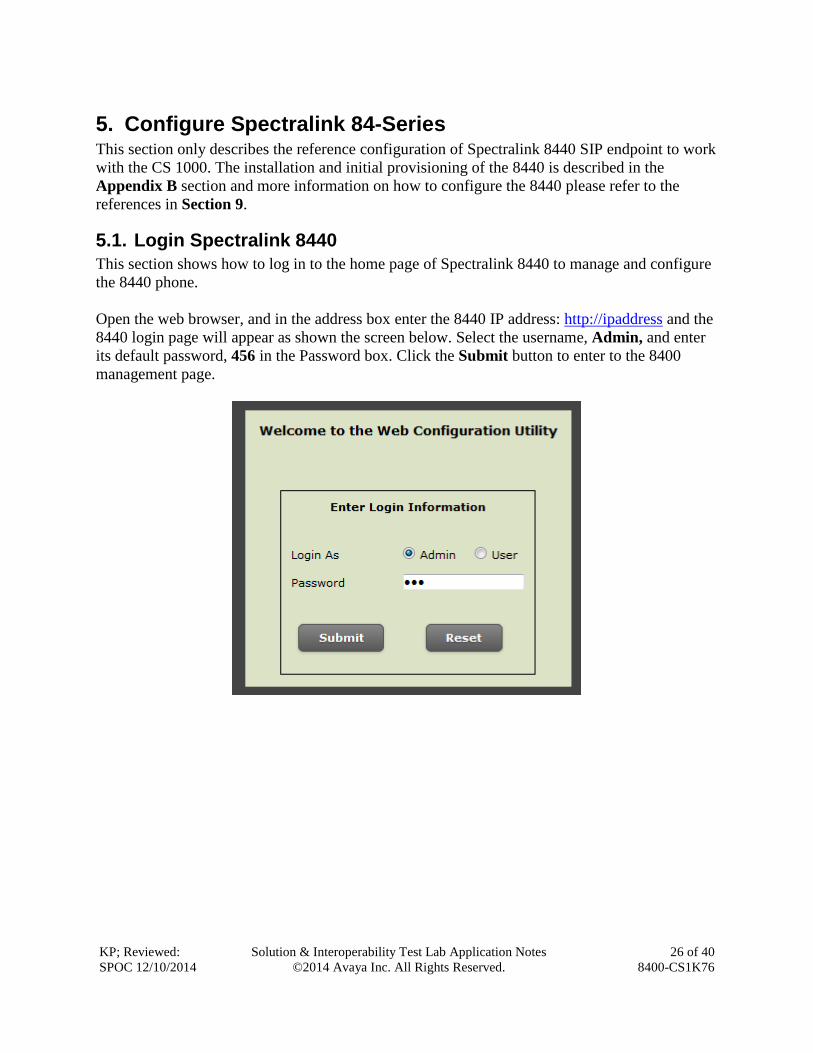
5.1. Login Spectralink 8440
This section shows how to log in to the home page of Spectralink 8440 to manage and configure
the 8440 phone.
Open the web browser, and in the address box enter the 8440 IP address: http://ipaddress and the
8440 login page will appear as shown the screen below. Select the username, Admin, and enter
its default password, 456 in the Password box. Click the Submit button to enter to the 8400
management page.
KP; Reviewed:
SPOC 12/10/2014
Solution & Interoperability Test Lab Application Notes
©2014 Avaya Inc. All Rights Reserved.
27 of 40
8400-CS1K76
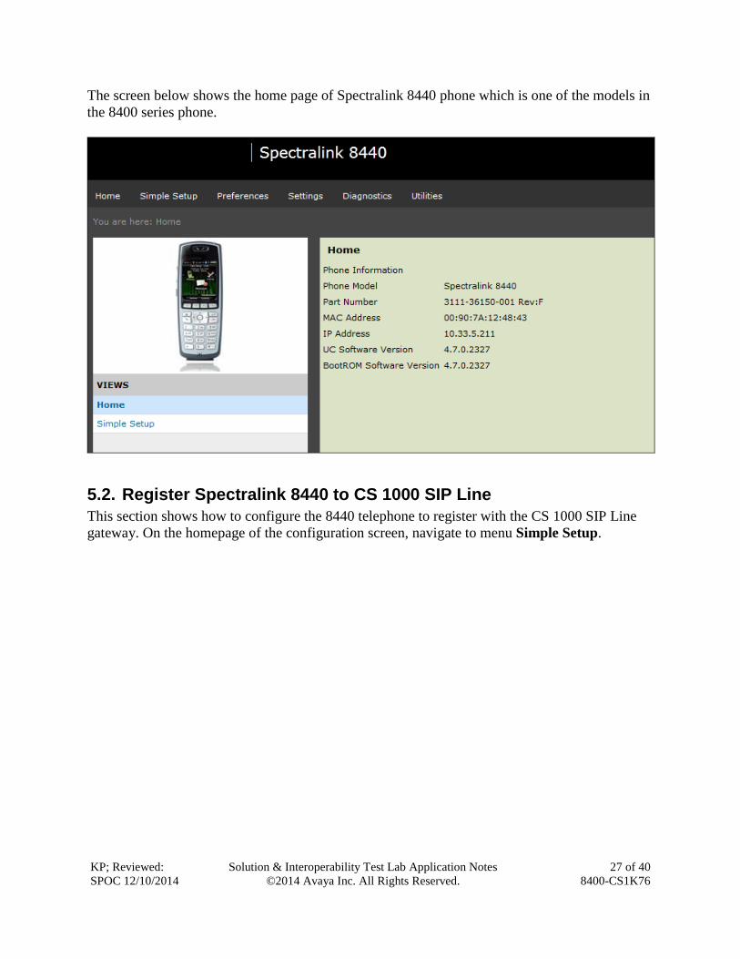
The screen below shows the home page of Spectralink 8440 phone which is one of the models in
the 8400 series phone.
5.2. Register Spectralink 8440 to CS 1000 SIP Line
This section shows how to configure the 8440 telephone to register with the CS 1000 SIP Line
gateway. On the homepage of the configuration screen, navigate to menu Simple Setup.

KP; Reviewed:
SPOC 12/10/2014
Solution & Interoperability Test Lab Application Notes
©2014 Avaya Inc. All Rights Reserved.
28 of 40
8400-CS1K76
The Simple Setup page is displayed as shown in the screen below. Enter the values as shown
below:
SIP Server: Address: enter 10.10.97.187 which is node IP address of CS 1000 SIP Line
server.
Port: enter 5060 which is local sip port of CS 1000 SIP Line.
SIP Outbound proxy:
Address: enter 10.10.97.187 Use the same Node IP address of SIP Line server.
Port: 5060
SIP Line Identification:
Display Name: Enter a descriptive name, e.g., 54009
Address: Enter 54009
Authentication User ID: enter 54009 This user ID that is configured in the
field SIPU of Terminal Number of SIP Line phone in the Section 5.11
Authentication Password: enter 1234 This password that is configured in the
field SCPW of UEXT Terminal Number for SIP Line phone in the Section 5.11
Click on the Save button to save changes. Note that the phone needs to be rebooted for the
changes to take effect.

KP; Reviewed:
SPOC 12/10/2014
Solution & Interoperability Test Lab Application Notes
©2014 Avaya Inc. All Rights Reserved.
29 of 40
8400-CS1K76
5.3. Configure Codec settings
This section shows how to set the codec on the Spectralink 8440 phone. The compliance testing
has been done on three codecs: G.711 Mu, G711A law and G729.
On the homepage of the 8440, navigate to menu Settings Audio Codec Priority, the Audio
Codec Priority page is displayed as shown below. The list of audio codecs being used appear
under the In use column. To use the codec G711Mu as the first choice, move it up to the top of
the In Use list, repeat the same procedure for other codecs. Click on the Save button to save
changes.
Note that the codec G.722 should not be used to avoid the transfer issue as mentioned in Section
2.2 Test Result.
KP; Reviewed:
SPOC 12/10/2014
Solution & Interoperability Test Lab Application Notes
©2014 Avaya Inc. All Rights Reserved.
30 of 40
8400-CS1K76
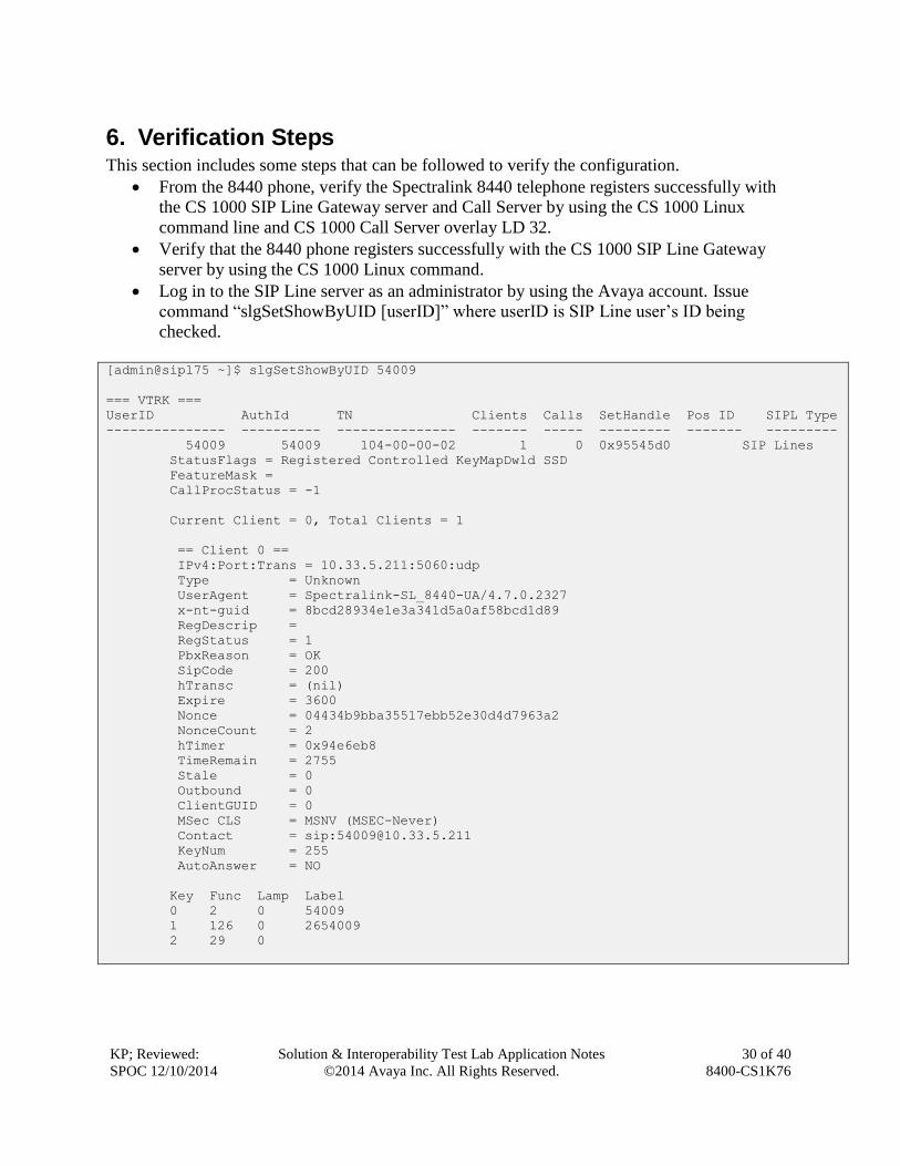
6. Verification Steps This section includes some steps that can be followed to verify the configuration.
From the 8440 phone, verify the Spectralink 8440 telephone registers successfully with
the CS 1000 SIP Line Gateway server and Call Server by using the CS 1000 Linux
command line and CS 1000 Call Server overlay LD 32.
Verify that the 8440 phone registers successfully with the CS 1000 SIP Line Gateway
server by using the CS 1000 Linux command.
Log in to the SIP Line server as an administrator by using the Avaya account. Issue
command “slgSetShowByUID [userID]” where userID is SIP Line user’s ID being
checked.
[admin@sipl75 ~]$ slgSetShowByUID 54009
=== VTRK ===
UserID AuthId TN Clients Calls SetHandle Pos ID SIPL Type
--------------- ---------- --------------- ------- ----- --------- ------- ---------
54009 54009 104-00-00-02 1 0 0x95545d0 SIP Lines
StatusFlags = Registered Controlled KeyMapDwld SSD
FeatureMask =
CallProcStatus = -1
Current Client = 0, Total Clients = 1
== Client 0 ==
IPv4:Port:Trans = 10.33.5.211:5060:udp
Type = Unknown
UserAgent = Spectralink-SL_8440-UA/4.7.0.2327
x-nt-guid = 8bcd28934e1e3a341d5a0af58bcd1d89
RegDescrip =
RegStatus = 1
PbxReason = OK
SipCode = 200
hTransc = (nil)
Expire = 3600
Nonce = 04434b9bba35517ebb52e30d4d7963a2
NonceCount = 2
hTimer = 0x94e6eb8
TimeRemain = 2755
Stale = 0
Outbound = 0
ClientGUID = 0
MSec CLS = MSNV (MSEC-Never)
Contact = sip:[email protected]
KeyNum = 255
AutoAnswer = NO
Key Func Lamp Label
0 2 0 54009
1 126 0 2654009
2 29 0

KP; Reviewed:
SPOC 12/10/2014
Solution & Interoperability Test Lab Application Notes
©2014 Avaya Inc. All Rights Reserved.
31 of 40
8400-CS1K76
Place a call from and to the 8440 telephone and verify that the call is established with 2-
way speech path.
During the call, use a pcap tool (Ethereal/Wireshark) at the SIP Line Gateway and clients
to make sure that all SIP request/response messages are correct.
7. Conclusion All of the executed test cases have passed and met the objectives outlined in Section 2.1, with
some exceptions outlined in Section 2.2. The Spectralink 84-Series SIP telephone version 4.7.0
is considered to be in compliance with Avaya Communication Server 1000 Release 7.6.
8. Additional References Product documentation for the Avaya CS 1000 products may be found at:
https://support.avaya.com/css/Products/
[1] Avaya CS 1000 Documents:
Avaya Communication Server 1000E Installation and Commissioning
Avaya Communication Server 1000 SIP Line Fundamental, Release 7.6
Avaya Communication Server 1000 Element Manager System Reference – Administration
Avaya Communication Server 1000 Co-resident Call Server and Signaling Server
Fundamentals
Avaya Communication Server 1000 Unified Communications Management Common
Services Fundamentals.
Avaya Communication Server 1000 ISDN Primary Rate Interface Installation and
Commissioning
Product documentation for the Spectralink 84-Series products may be found at:
http://www.spectralink.com/product-information/wi-fi/spectralink-84-series-wireless-
telephones
KP; Reviewed:
SPOC 12/10/2014
Solution & Interoperability Test Lab Application Notes
©2014 Avaya Inc. All Rights Reserved.
32 of 40
8400-CS1K76
Appendix B The Spectralink Software that you download contains configuration file templates, valid XML
files that you can edit using an XML editor. These files contain all the parameters explained in
this document that provision the handsets with features and settings. The configuration files are
very flexible: you can rearrange the parameters within the file, move parameters to new files, or
create your own configuration files with only those parameters you want. This flexibility is
useful when you want to apply the same features and settings to a large number of handsets. Use
of the configuration files to provision the handsets with features and settings is called the
centralized provision method – the configuration files enable you to store a single set of
configuration files on a central provisioning server and configure all of your handsets to read the
same set of files. You can also configure a subset of handsets to use only specific files, thereby
deploying different handsets with different sets of features.
Spectralink recommends that you configure handsets using the centralized
provisioning method. By default, Spectralink sets FTP as the provisioning protocol on all
Spectralink handsets. However, you can also configure individual handsets using the handset’s
menu system, accessible through the local user keypad interface, or you can configure select
parameters by using the Web Configuration Utility.
You will need to keep in mind that there is a hierarchy among the configuration methods and
settings. Using a higher-priority method will override settings you make using a lower-priority
method. The following lists all of the available ways to set features and settings for the handsets.
Spectralink strongly recommends becoming familiar with each of the configuration methods.
To download the Spectralink Software:
1 Access Spectralink Software from the Spectralink Support Website:
http://support.spectralink.com/products/wi-fi/spectralink-84-series-wireless-telephone
2 Acknowledge that you read the notices, accept the agreement, and choose Submit.
3 Save the Spectralink Software ZIP file download.
4 Extract (uncompress) the ZIP file.
Copy all files from the distribution ZIP file to working directory on the provisioning server,
maintaining the same folder hierarchy. To simplify provisioning, Spectralink recommends, as a
best practice, to start creating new configuration files from unedited template files containing the
default values. Rename the template file to your specific file name as you configure and add
specific parameter values for your site.

KP; Reviewed:
SPOC 12/10/2014
Solution & Interoperability Test Lab Application Notes
©2014 Avaya Inc. All Rights Reserved.
33 of 40
8400-CS1K76
You can create as many configuration files as you want and your configuration files can contain
any combination of parameters you put in them. You can put all parameters into one file or, for
example, you can put SIP server parameters in one file and handset features parameters in
another file. Configuration file variances are explained in the Spectralink 84-Series Wireless
Telephone Deployment Guide: http://support.spectralink.com/resources/spectralink-84-series-
wireless-telephone-deployment-guide.
For large-scale deployments, the centralized provisioning method using configuration files is
strongly recommended. For smaller scale deployments, the Web Configuration Utility or local
interface may be used, but administrators need to be aware that settings made using these
methods will override settings made using configuration files.
Authenticate the 8400 telephone to the wireless network
Because the handsets cannot access the wireless LAN before their wireless settings are
configured, you will need to establish a wired connection between a computer and each handset
and load the wireless settings via a USB Micro B connection. We will call this computer the
initial provisioning computer. It is a temporary setup and does not require exceptional resources
in the computer. Only one 84-Series handset is loaded at a time. Requirements are:

KP; Reviewed:
SPOC 12/10/2014
Solution & Interoperability Test Lab Application Notes
©2014 Avaya Inc. All Rights Reserved.
34 of 40
8400-CS1K76
KP; Reviewed:
SPOC 12/10/2014
Solution & Interoperability Test Lab Application Notes
©2014 Avaya Inc. All Rights Reserved.
35 of 40
8400-CS1K76
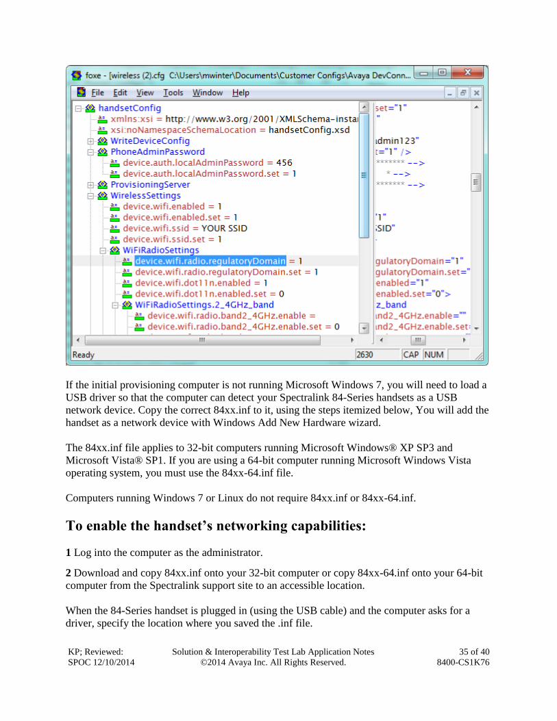
If the initial provisioning computer is not running Microsoft Windows 7, you will need to load a
USB driver so that the computer can detect your Spectralink 84-Series handsets as a USB
network device. Copy the correct 84xx.inf to it, using the steps itemized below, You will add the
handset as a network device with Windows Add New Hardware wizard.
The 84xx.inf file applies to 32-bit computers running Microsoft Windows® XP SP3 and
Microsoft Vista® SP1. If you are using a 64-bit computer running Microsoft Windows Vista
operating system, you must use the 84xx-64.inf file.
Computers running Windows 7 or Linux do not require 84xx.inf or 84xx-64.inf.
To enable the handset’s networking capabilities:
1 Log into the computer as the administrator.
2 Download and copy 84xx.inf onto your 32-bit computer or copy 84xx-64.inf onto your 64-bit
computer from the Spectralink support site to an accessible location.
When the 84-Series handset is plugged in (using the USB cable) and the computer asks for a
driver, specify the location where you saved the .inf file.

KP; Reviewed:
SPOC 12/10/2014
Solution & Interoperability Test Lab Application Notes
©2014 Avaya Inc. All Rights Reserved.
36 of 40
8400-CS1K76
Download the wireless configuration to the handset
1 Ensure that the initial provisioning computer is functioning as an FTP server.
2 On the initial provisioning computer load the wireless.cfg file into the FTP root directory.
3 Apply power to 84xx handset.
4 Connect micro-USB cable between the 84xx handset and initial provisioning computer.
5 (Conditional) The Found New Hardware wizard opens. Connecting the handset to the initial
provisioning computer launches the Found New Hardware wizard automatically. The Found
New Hardware wizard only displays the first time you use each USB slot on your computer.
a Select No, not this time, and click Next.
b Select Install from a list or specific location (Advanced) and click Next.
c Select Search for the best driver in these locations.
d Select the check box for Include this location in the search:
e Browse to your 84xx.inf or 84xx-64.inf and click Next.
f The Linux USB Ethernet/RNDIS Gadget is installed.
g A warning will be displayed indicating this driver has not passed Windows Logo
testing. Select Continue Anyway.
h Click Finish.
6 The handset will download the wireless configuration and then reboot making a tweedle noise
when finished.
7 (Conditional) If handsets do not immediately (within 10 seconds) download and reboot after
plugging the USB into them, you can manually force the configuration download by navigating
to the Settings menu on the handset: Settings> (1)Basic Settings> (6)Update Configuration>
Yes. If you use this option, Updating… remains on the display until it is finished.
8 Once the handset reboots, disconnect the USB cable from 84xx handset and allow it to
download the rest of its configuration files from the provisioning server.
9 Test the first few handsets to be sure your configuration is working as desired.

KP; Reviewed:
SPOC 12/10/2014
Solution & Interoperability Test Lab Application Notes
©2014 Avaya Inc. All Rights Reserved.
37 of 40
8400-CS1K76
This section shows how to configure the 8400 telephone to register with the CS 1000 SIP Line
gateway. Each phone is deployed to a specific extension and all phones have similar parameters.
In this deployment, phones are typically linked to extensions which are then assigned to users.
You will need to create one .cfg file for each extension/user.
In our example, these three files are provisioned:
ite.cfg

KP; Reviewed:
SPOC 12/10/2014
Solution & Interoperability Test Lab Application Notes
©2014 Avaya Inc. All Rights Reserved.
38 of 40
8400-CS1K76
The site.cfg template contains most common parameters including network and
telephony information that pertains to all of the handsets, such as SIP servers, dial plan, etc.
.
-ext.cfg (one file for each extension/handset)

KP; Reviewed:
SPOC 12/10/2014
Solution & Interoperability Test Lab Application Notes
©2014 Avaya Inc. All Rights Reserved.
39 of 40
8400-CS1K76
You must create a specific <MACaddress>-ext.cfg file for each phone/extension you deploy.
The User spreadsheet you completed that lists each extension/user and the MACaddress of the
phone assigned to that extension will help you create these files.
These files must be named with the identical structure as the variable used by the phone to find
it. Therefore when the variable [PHONE_MAC_ADDRESS]-ext.cfg is used, the phone-specific
files must be named <MACaddress>-ext.cfg.You will use the MACaddress-ext.cfg template to
create the files for each extension/user. It contains the most common parameters, including
network and telephony information, that pertain to all of the handsets, such as SIP servers, dial
plan, etc.

KP; Reviewed:
SPOC 12/10/2014
Solution & Interoperability Test Lab Application Notes
©2014 Avaya Inc. All Rights Reserved.
40 of 40
8400-CS1K76
©2014 Avaya Inc. All Rights Reserved.
Avaya and the Avaya Logo are trademarks of Avaya Inc. All trademarks identified by ® and
™ are registered trademarks or trademarks, respectively, of Avaya Inc. All other trademarks
are the property of their respective owners. The information provided in these Application
Notes is subject to change without notice. The configurations, technical data, and
recommendations provided in these Application Notes are believed to be accurate and
dependable, but are presented without express or implied warranty. Users are responsible for
their application of any products specified in these Application Notes.
Please e-mail any questions or comments pertaining to these Application Notes along with the
full title name and filename, located in the lower right corner, directly to the Avaya
DevConnect Program at [email protected].