application note an 102 data-logging using the vinculum vnc1l · the code for the pic...
TRANSCRIPT
Future Technology Devices International Limited (FTDI)
373 Scotland Street, Glasgow G5 8QB United Kingdom Tel.: +44 (0) 141 429 2777 Fax: + 44 (0) 141 429 2758
E-Mail (Support): [email protected] Web: http://www.ftdichip.com
Future Technology Devices International Ltd.
Application Note AN_102
Data-Logging Using the Vinculum
VNC1L
Document Reference No.: FT_000058
Version 2.00
Issue Date: 2008-08-28
This application note describes methods for interfacing a data-logging application to a VNC1L. The examples demonstrate using the UART Interface, Command Monitor, USB device commands and disk
access commands of the VNC1L.
The techniques used in this application note are applicable to the whole range of VNC1L-based modules
and applications.

Document Reference No.: FT_000058
Data-Logging Using the Vinculum VNC1L Application Note AN_102 Version 2.00
Clearance No.: FTDI# 56 Table of Contents
1 Preface ................................................................................................... 3
1.1 Conventions ......................................................................................................... 3
1.2 Acronyms and Abbreviations ............................................................................. 4
2 Introduction............................................................................................ 5
3 Requirements ......................................................................................... 6
3.1 Hardware .............................................................................................................. 6
3.2 Firmware .............................................................................................................. 7
3.3 Software ............................................................................................................... 7
3.3.1 VLogger ................................................................................................................................... 7
3.3.2 VAcq ........................................................................................................................................ 8
4 UART Interface Module ......................................................................... 9
4.1 Pin Definitions ..................................................................................................... 9
4.2 External Functions .............................................................................................. 9
4.2.1 uartInit .................................................................................................................................... 10
4.2.2 uartRead ................................................................................................................................ 10
4.2.3 uartReadWait ......................................................................................................................... 11
4.2.4 uartWrite ................................................................................................................................ 11
4.3 Interrupt Functions ............................................................................................ 11
4.3.1 uartRx .................................................................................................................................... 11
5 Command Monitor Module .................................................................. 13
5.1 External Functions ............................................................................................ 13
5.1.1 monSendByte ........................................................................................................................ 13
5.1.2 monCmdSend ........................................................................................................................ 14
5.1.3 monCmdSendByteParam ...................................................................................................... 14
5.1.4 monCmdSendParam ............................................................................................................. 14
5.1.5 monResponse ........................................................................................................................ 15
5.1.6 monPrompt ............................................................................................................................ 15
5.2 Internal Functions ............................................................................................. 15
5.3 Interrupts ............................................................................................................ 16
6 Common Application Code ................................................................. 17
6.1 Initialisation ........................................................................................................ 17
6.2 Storage Directory Creation ............................................................................... 17
6.3 Unique Filename Creation ................................................................................ 18
6.4 Completing Sampling ........................................................................................ 19
7 VLogger Application ............................................................................ 20

Document Reference No.: FT_000058
Data-Logging Using the Vinculum VNC1L Application Note AN_102 Version 2.00
Clearance No.: FTDI# 56 7.1 USB Device Identification ................................................................................. 20
7.2 Disk Detection .................................................................................................... 21
7.3 Sample Request and Sample Read .................................................................. 22
7.4 Data Storage ...................................................................................................... 23
7.5 Data File Format ................................................................................................ 24
8 VAcq Application ................................................................................. 25
8.1 Disk Detection .................................................................................................... 25
8.2 Data Storage ...................................................................................................... 25
8.3 Data File Format ................................................................................................ 27
9 Summary .............................................................................................. 28
10 Contact Information............................................................................. 29
Appendix A - References .......................................................................... 30
Appendix B - List of Figures and Tables .................................................. 31
Appendix C - Revision History .................................................................. 32

Document Reference No.: FT_000058
Data-Logging Using the Vinculum VNC1L Application Note AN_102 Version 2.00
Clearance No.: FTDI# 56
1 Preface
The objective of this document is to demonstrate the use of a VNC1L device in data logging projects.
Any software code examples given in this document are for information only. The examples are not
guaranteed and are not supported by FTDI.
1.1 Conventions
The following conventions are used in this document:
Convention Description
Monospaced type Indicates input or output from the monitor.
Boldface monospaced type Indicates input supplied by the user.
Italic monospaced type Indicates binary characters.
Important Signals that the information supplied is important.
Note Provide additional information about a topic.
Warning Indicate potential damage to equipment or loss of data.
: Is used to show a range. For instance, a range of bits 15:9 is bits 15 to 9
(inclusive) of a binary value.
VNC1L Indicated information specific to the VNC1L device.
� carriage return (0x0D).
· space (0x20).
d Represents a single decimal character (0 to 9).
x Represents a single hexadecimal character (0 to 9 and A to F).
c Represents a binary character (0x00 to 0xFF).
Table 1.1 Document Conventions

Document Reference No.: FT_000058
Data-Logging Using the Vinculum VNC1L Application Note AN_102 Version 2.00
Clearance No.: FTDI# 56
1.2 Acronyms and Abbreviations
The following terms are used within this document:
Terms Description
8.3
A filename format consisting of 1 to 8 characters, optionally followed by a period
(‘.’) then an extension of up to 3 characters. For example, “TEST.TXT”,
“ANEWFILE.1” or “AFILE”.
FAT
File Allocation Table. The name for the file system typically used for USB Flash
Disks. Variants are FAT12, FAT16 and FAT32, the numbers referring to the
number of bits used to specify a cluster on the disk.
BOMS Bulk Only Mass Storage. A general description given to a USB mass storage device
e.g. USB Flash Disk.
Monitor Command line interface which allows instructions to be given to the VNC1L and
responses to be returned.
Sector Size The size of data which is read from or written to a disk in a single operation.
Table 1.2 Acronyms and Abbreviations

Document Reference No.: FT_000058
Data-Logging Using the Vinculum VNC1L Application Note AN_102 Version 2.00
Clearance No.: FTDI# 56
2 Introduction
The VNC1L IC and firmware libraries provided by FTDI allow embedded systems to communicate easily with USB devices. Using the VNC1L device, microcontrollers can now be interfaced with a range of USB
devices including Bulk Only Mass Storage Class (BOMS), Communication Device Class (CDC), Printer Class, Human Interface Device (HID) class devices and USB hubs.
This application note provides a practical demonstration of the capabilities of the VNC1L. It shows how to program a PIC microcontroller to issue commands to the firmware command monitor of the VNC1L in
order to control a VEval board.
The ESUART interface on a PIC microcontroller is connected to the UART interface on the VNC1L. Code
modules are used to send and receive commands and data to the VNC1L as well as managing and decoding the responses from the VNC1L.
Two applications are described: the first application is a simple data logger which reads values from a USB tilt sensor module and records the data on a USB Flash disk, the second application is described for
sampling an analogue input to the PIC microcontroller and storing the data on a USB Flash disk.
Implementation details for communicating with the VNC1L using the UART interface are provided. Disk
and USB device access commands are also described in detail. Other features of the projects that are not specifically related to the function of the VNC1L device and are left to the user to interpret.

Document Reference No.: FT_000058
Data-Logging Using the Vinculum VNC1L Application Note AN_102 Version 2.00
Clearance No.: FTDI# 56
3 Requirements
3.1 Hardware
This application note requires a VEval board, a Microchip PICDEM 4 Demo Board and a connecting cable. Two demonstration projects are described. The first, VLogger, requires a DLP-TILT USB module as a data
source. The second, VAcq, uses an ST Microelectronics accelerometer development module as an analogue input source.
On the PICDEM 4 board a PIC18F1320 microcontroller is needed to run the provided code.
Figure 3.1 VLogger Application Demo Hardware
The connecting cable comprises four I/O signals, +5V and GND signals. The I/O signals carry the UART
interface signals – Tx, Rx, CTS and RTS. Table 3.1 shows the connections required on the VEval board. Table 3.2 lists the connections for the cable on the PICDEM 4 board.
Pin Number Signal Name Colour
AD3 CTS# Green
AD0 Tx Orange
AD1 Rx Yellow
+5V +5V Red
AD2 RTS# Brown
GND GND Black
Table 3.1 VEval Connections

Document Reference No.: FT_000058
Data-Logging Using the Vinculum VNC1L Application Note AN_102 Version 2.00
Clearance No.: FTDI# 56
Pin Number Signal Name Colour
RB3 RTS# Green
RB1 Rx Yellow
RB4 Tx Orange
+5V +5V Red
RB2 CTS# Brown
GND GND Black
Table 3.2 PICDEM 4 Connections
The VEval board must have jumpers JP1 and JP2 set to UART mode – refer to the VEval board User Manual.
J10 on the PICDEM 4 board must be set to select PIC18 operation mode. By default the project code is set to use the internal oscillator on the PIC microcontroller. J24 must also be removed to disconnect the
RA0 potentiometer and allow the accelerometer output to be connected to the RA0 input. The Vx output of the accelerometer was connected to the RA0 input of the PIC using the prototype area of the PICDEM 4
module.
A USB Flash disk is connected to USB Port 2 on the VEval board.
In this configuration, only the PICDEM 4 board should be powered. The VEval board will be powered by 5V supplied from the PICDEM 4 board. The VEval board will convert the supply to 3.3V for use by the
VNC1L and the ST Microelectronics accelerometer.
3.2 Firmware
The VNC1L device on the VEval board must be programmed with VDAP firmware version V3.64 or later
for these projects. The VNC1L firmware commands are fully documented in the VNC1L Firmware User Manual.
3.3 Software
Sample C code for the PIC18F1320 microcontroller is available as a free download from the FTDI web
site. The code for the PIC microcontroller must be compiled with SourceBoost C or ported to an equivalent compiler before being programmed onto the device.
Two sample applications are provided in this application note. Common code is used to manage the UART
interface and the command monitor.
USB Flash disks are also used by both applications although the methods used for writing data to files is different.
3.3.1 VLogger
The VLogger sample application demonstrates a method of requesting and receiving data from a USB
sensor device connected to USB Port 1 on the VEval board. Data is stored on a USB Flash disk on USB
Port 2.
The USB device used is a DLP-TILT module which consists of an accelerometer and PIC microcontroller interfaced to USB using an FT232 device.
The connector described in Table 3.1 and Table 3.2 is represented by the grey double headed arrow in Figure 2.

Document Reference No.: FT_000058
Data-Logging Using the Vinculum VNC1L Application Note AN_102 Version 2.00
Clearance No.: FTDI# 56
Figure 2 VLogger Connection Diagram
This application shows how to setup communications with a USB device and how to send data to and receive data from a device.
3.3.2 VAcq
In the VAcq program, an analogue sensor is connected directly to an Analogue to Digital Converter input
of the PIC microcontroller. Timed samples of the sensor output are stored on a USB Flash disk on USB Port 2 of the VEval board.
The analogue data source used in this case is an STEVAL-MKI010V1 MEMS accelerometer from ST Microelectronics. This supplies analogue voltage outputs for X, Y and Z-axis. Only the output from one
axis is connected to the PIC microcontroller.
The connector described in Table 3.1 and Table 3.2 is represented by the grey double headed arrow in
Figure 3. The connection between the accelerometer and the PICDEM 4 board is shown by the white
arrow.
The accelerometer must be powered by a 3.3V supply. The VEval board derives 3.3V from the 5V drawn
from the PICDEM4 board. This can be used, with additional wiring, for the accelerometer or a dedicated voltage regulator can be placed on the PICDEM 4 board to supply 3.3V.
Figure 3 VAcq Connection Diagram
The application shows how to batch data to stream to a USB Flash disk for maximum performance.
Port 2
Port 1
VEval
Flash Disk
Accelerometer
PICDEM 4
DLP-TILT
Port 2
Port 1
VEval
PICDEM 4
Flash Disk

Document Reference No.: FT_000058
Data-Logging Using the Vinculum VNC1L Application Note AN_102 Version 2.00
Clearance No.: FTDI# 56
4 UART Interface Module
The UART interface module controls the application’s physical communication with the UART interface on the VNC1L. The files UART.c and UART.h manage the EUSART interface of the PIC microcontroller and
perform RTS/CTS flow control.
The code creates a software FIFO buffer for data received by the PIC microcontroller from the VNC1L. An
interrupt is generated by the PIC microcontroller each time a character is received and this data is added to the FIFO buffer. The application can query the FIFO buffer to determine if data has been received.
Data is transmitted by the PIC microcontroller sequentially without the use of buffering.
Flow control is handled by the UART interface module to ensure data is sent only when the receiving
device is ready.
Each callable function in the UART interface module is aliased using a pre-processor definition to allow
the entire module to be replaced by a functionally equivalent module for handling communications. In the case of the VNC1L this may be an SPI or Parallel FIFO interface. The calling application should only use
the generic interface routine names and not the UART-specific ones. The definitions included in the UART.h file and are shown in Figure 3.
Figure 4.1 Monitor Callable Functions for UART Interface
4.1 Pin Definitions
The UART interface between the PICDEM 4 and the VNC1L on the VEval board utilises 4 signals. The pin
definitions for the signals used by the UART interface on the PIC microcontroller are shown in Figure 4.
Figure 4.2 UART Pin Definition Code
The UART interface pins on the VNC1L are listed in the VNC1L Datasheet and VNC1L Firmware User
Manual. Tx on the PIC microcontroller must be connected to Rx on the VNC1L, Rx on the PIC to Tx on the VNC1L, similarly CTS# and RTS# must also be crossed.
4.2 External Functions
The UART interface code presents 4 subroutines externally:
• uartInit – initialise the EUSART registers and interface I/O pins on the PIC microcontroller.
• uartRead – check UART interface for available byte of data.
• uartReadWait – wait until a byte is received on the UART interface.
• uartWrite – write a byte of data to the UART interface.
#define PORT_RX portb.1 // RX is RB1 (Port B bit 1) #define TRIS_RX trisb.1 #define PORT_RTS portb.3 // RTS# is RB3 (Port B bit 3) #define TRIS_RTS trisb.3 #define PORT_TX portb.4 // TX is RB4 (Port B bit 4) #define TRIS_TX trisb.4 #define PORT_CTS portb.2 // CTS# is RB2 (Port B bit 2) #define TRIS_CTS trisb.2
#define monInit uartInit #define monRead uartRead #define monReadWait uartReadWait #define monWrite uartWrite #define monInterrupt pir1.RCIF #define monInterruptHandler uartRx

Document Reference No.: FT_000058
Data-Logging Using the Vinculum VNC1L Application Note AN_102 Version 2.00
Clearance No.: FTDI# 56 These subroutines are called by the command monitor module (see Section 5) to allow an application to interact with the VNC1L firmware.
4.2.1 uartInit
Initialise the PIC microcontroller EUSART interface and the UART FIFO buffer.
Definition
void uartInit()
Parameters
None
Return Value
None
Calls
None
Remarks
This routine sets up the PIC microcontroller EUSART interface and flow control pins. RTS# is configured
as an output and CTS# as an input. The RTS# output is set low to signal the PIC microcontroller is able to accept data.
The EUSART is initialised to 9600 baud, 1 stop bit, no parity. These UART settings are the default settings on the VNC1L firmware. The Vinculum Firmware Customiser Application (available from the FTDI website)
can be used to modify these values.
Interrupts are enabled to allow data from the VNC1L command monitor to be added to the UART FIFO
buffer.
4.2.2 uartRead
Return a byte of data from the UART FIFO buffer.
Definition
char uartRead(char *pUartData)
Parameters
*pUartData – pointer to variable to receive data read from UART FIFO buffer.
Return Value
Zero if data read successful, 1 if unsuccessful.
Calls
None
Remarks
If data is available in the UART FIFO buffer this routine will move the first byte of data from the buffer to
the byte pointed to by parameter pUartData and return zero. If no data is present in the UART FIFO buffer then the routine will return 1.
If the number of data bytes stored in the UART FIFO buffer falls below a lower threshold value then the routine will set the RTS# pin low (active) allowing more data to be sent to the PIC microcontroller by the
VNC1L.

Document Reference No.: FT_000058
Data-Logging Using the Vinculum VNC1L Application Note AN_102 Version 2.00
Clearance No.: FTDI# 56 4.2.3 uartReadWait
Wait until a byte of data is available from the UART FIFO buffer.
Definition
char uartReadWait()
Parameters
None
Return Value
Data read from UART FIFO buffer.
Calls
uartRead
Remarks
Repeatedly calls uartRead until a byte of data is available in the UART FIFO buffer. The byte of data
received from uartRead is returned.
4.2.4 uartWrite
Write a single byte of data to the EUSART on the PIC microcontroller.
Definition
void uartWrite(char uartData)
Parameters
uartData – data to write to the UART interface.
Return Value
None
Calls
None
Remarks
This routine waits until any previous data transmission has been completed before transmitting the byte
to the EUSART. Then it checks that the CTS# input is active (low) before proceeding with the transmission. This ensures that the VNC1L is ready to accept data from the PIC microcontroller.
4.3 Interrupt Functions
The monInterrupt definition is used in the application’s interrupt handler routine to route interrupts to the
monInterruptHandler routine for servicing.
4.3.1 uartRx
Interrupt handler routine for receiving data from the EUSART on the PIC microcontroller.
Definition
void uartRx()
Parameters
None
Return Value
None

Document Reference No.: FT_000058
Data-Logging Using the Vinculum VNC1L Application Note AN_102 Version 2.00
Clearance No.: FTDI# 56 Calls
None
Remarks
When a EUSART interrupt is signalled the application interrupt handler must call this routine to service
the interrupt. The interrupt status bit in the PIC microcontroller interrupt request register is reset.
The interrupt handler reads a byte of data received from the EUSART controller on the PIC
microcontroller and adds it to the UART FIFO buffer.
The RTS# output is set high (inactive) if the number of data bytes stored in the UART FIFO buffer
reaches an upper threshold.

Document Reference No.: FT_000058
Data-Logging Using the Vinculum VNC1L Application Note AN_102 Version 2.00
Clearance No.: FTDI# 56
5 Command Monitor Module
The command monitor module calls subroutines in the UART interface module to communicate with the VNC1L firmware. Source code provided in the monitor.c and monitor.h files controls the sending of
commands to the VNC1L, and receiving and interpreting the responses.
There are several responses which can come from each command sent to the VNC1L firmware. Figure 5
lists the enumeration of these responses from the VNC1L firmware from the monitor.h file.
Figure 5.1 Monitor Response Enumeration
5.1 External Functions
5.1.1 monSendByte
Send a single byte of data to the VNC1L.
Definition
void monSendByte(char monData)
Parameters
monData – byte of data to write to interface.
Return Value
None
Calls
monWrite
Remarks
This command transfers a byte of data to the UART interface module. It has an inline specifier due to the simplicity of the function.
// Prompts and messages returned by VNC1L in Short Command Set enum vResponse { // Prompts returned by all VNC1L firmware Resp_Prompt_OK, // > (Success) Resp_Prompt_ND, // ND (Success) Resp_Prompt_UE, // E echo Resp_Prompt_LE, // e echo Resp_Prompt_CF, // CF (Command Failed) Resp_Prompt_BC, // BC (Bad Command) Resp_Prompt_DF, // DF (Disk Full) Resp_Prompt_FI, // FI (File Invalid) Resp_Prompt_RO, // RO (Read Only) Resp_Prompt_FO, // FO (File Open) Resp_Prompt_NE, // NE (Dir Not Empty) Resp_Prompt_FN, // FN (Filename Invalid) Resp_Prompt_End, // Asynchronous messages returned by all VNC1L firmware Resp_Message_NU, // NU / No Upgrade Resp_Message_DD1, // DD1 / Device Detected USB Port 1) Resp_Message_DD2, // DD2 / Device Detected USB Port 2) Resp_Message_DR1, // DR1 / Device Removed USB Port 1) Resp_Message_DR2, // DR2 / Device Removed USB Port 2) Resp_Message_Splash, // Ver ... Resp_None = 0xff,
};

Document Reference No.: FT_000058
Data-Logging Using the Vinculum VNC1L Application Note AN_102 Version 2.00
Clearance No.: FTDI# 56 5.1.2 monCmdSend
Send a command with no parameters to the VNC1L.
Definition
void monCmdSend(char monCmd)
Parameters
monCmd – command byte to write to interface.
Return Value
None
Calls
monWrite
Remarks
This command writes the command byte passed as a parameter to the UART interface module. It follows
the command byte with a carriage return character if required.
5.1.3 monCmdSendByteParam
Send a command with a single byte parameter to the VNC1L.
Definition
void monCmdSendByteParam(char monCmd, unsigned char monParam)
Parameters
monCmd – command byte to write to interface.
monParam – single byte to be sent as parameter.
Return Value
None
Calls
monWrite
Remarks
This command writes the command byte passed as a parameter to the UART interface module. Then it sends a space character to delimit the parameter. The single-byte parameter monParam is sent followed
by a carriage return.
5.1.4 monCmdSendParam
Send a command with a variable parameter length to the VNC1L.
Definition
void monCmdSendParam(char monCmd, unsigned char monCount, unsigned char *pmonParam)
Parameters
monCmd – command byte to write to interface. monCount – count of bytes to send as parameters to interface.
*pmonParam – pointer to array of bytes to be sent as parameters.
Return Value
None
Calls
monWrite

Document Reference No.: FT_000058
Data-Logging Using the Vinculum VNC1L Application Note AN_102 Version 2.00
Clearance No.: FTDI# 56 Remarks
This command writes the command byte passed as a parameter to the UART interface module. Then it
sends a space character to delimit the parameters. The parameters consist of monCount bytes; the data is passed in the pmonParam array. The command and parameters are followed by a carriage return.
5.1.5 monResponse
Wait until a valid prompt, error message or status message is returned by the VNC1L.
Definition
enum vResponse monResponse()
Parameters
None
Return Value
Enumeration of prompt or error response command returns.
Calls
monRead
Remarks
After a command has been sent to the VNC1L, it will always return a response indicating success or an
error condition. The monResponse subroutine compares the data returned from the command monitor to a list of expected responses and returns a matching value from an enumeration list. This can be used by
the calling application to check for the expected behaviour of the device.
5.1.6 monPrompt
Wait until a valid prompt or error message is returned by the VNC1L.
Definition
enum vResponse monPrompt()
Parameters
None
Return Value
Enumeration of prompt or error response command returns.
Calls
monResponse
Remarks
In the enumeration vResponse, Resp_Prompt_End marks the last valid prompt or error message in the
list. Subsequent values indicate asynchronous messages which may be sent by the VNC1L.
5.2 Internal Functions
There are no internal functions in the command monitor module.

Document Reference No.: FT_000058
Data-Logging Using the Vinculum VNC1L Application Note AN_102 Version 2.00
Clearance No.: FTDI# 56 5.3 Interrupts
To allow the command monitor to receive data from the UART Interface Module it requires the code in Figure 5.2 to be included in the interrupt() handler of the application.
Figure 5.2 Interrupt Handling
// handle interrupts (if any) from monitor if (monInterrupt) { monInterruptHandler(); }
Document Reference No.: FT_000058
Data-Logging Using the Vinculum VNC1L Application Note AN_102 Version 2.00
Clearance No.: FTDI# 56
6 Common Application Code
The code in this section is used by the VLogger and VAcq applications.
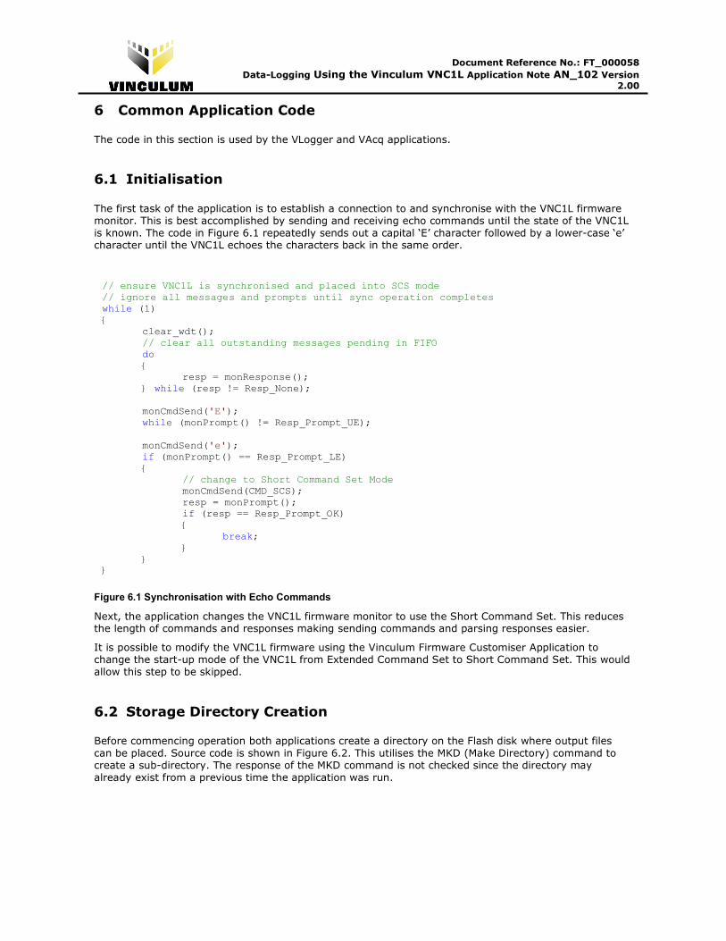
6.1 Initialisation
The first task of the application is to establish a connection to and synchronise with the VNC1L firmware monitor. This is best accomplished by sending and receiving echo commands until the state of the VNC1L
is known. The code in Figure 6.1 repeatedly sends out a capital ‘E’ character followed by a lower-case ‘e’ character until the VNC1L echoes the characters back in the same order.
Figure 6.1 Synchronisation with Echo Commands
Next, the application changes the VNC1L firmware monitor to use the Short Command Set. This reduces the length of commands and responses making sending commands and parsing responses easier.
It is possible to modify the VNC1L firmware using the Vinculum Firmware Customiser Application to change the start-up mode of the VNC1L from Extended Command Set to Short Command Set. This would
allow this step to be skipped.
6.2 Storage Directory Creation
Before commencing operation both applications create a directory on the Flash disk where output files
can be placed. Source code is shown in Figure 6.2. This utilises the MKD (Make Directory) command to create a sub-directory. The response of the MKD command is not checked since the directory may
already exist from a previous time the application was run.
// ensure VNC1L is synchronised and placed into SCS mode // ignore all messages and prompts until sync operation completes while (1) { clear_wdt();
// clear all outstanding messages pending in FIFO do { resp = monResponse(); } while (resp != Resp_None);
monCmdSend('E');
while (monPrompt() != Resp_Prompt_UE); monCmdSend('e'); if (monPrompt() == Resp_Prompt_LE)
{ // change to Short Command Set Mode monCmdSend(CMD_SCS); resp = monPrompt(); if (resp == Resp_Prompt_OK) {
break; }
} }

Document Reference No.: FT_000058
Data-Logging Using the Vinculum VNC1L Application Note AN_102 Version 2.00
Clearance No.: FTDI# 56
Figure 6.2 Directory Creation
The applications perform a CD (Change Directory) command into the directory. If the directory does not
exist or it is unable to perform the command then it will report an error.
6.3 Unique Filename Creation
The next operation is to parse the output of the DIR (Directory List) command to create a unique filename - Figure 6.3. A template filename is generated and the numeric value incremented until no files
with that exact name are detected.
Figure 6.3 Unique Filename Creation
// create template for unique filename for (i = 0; i < 12; i++) { filename[i] = fileFormat[i]; } // loop through possible filenames until a unique combination found while (1) { // perform a dir to see if filename exists monCmdSendParam(CMD_DIR, 11, filename); // carriage return preceeds file information returned by dir command monReadWait(); // an OK prompt indicates file already exists resp = monPrompt(); if (resp != Resp_Prompt_OK) { // filename does not exist on disk (filename is unique) break; // from while } // increment counter in filename for (i = 7; i > 3; i--) { if (++filename[i] > '9') { filename[i] = '0'; } else { break; // from for loop } } }
// create logging directory for (i = 0; i < 4; i++) { filename[i] = dirName[i]; } monCmdSendParam(CMD_MKD, 4, filename); resp = monPrompt(); // change directory to logging directory monCmdSendParam(CMD_CD, 4, filename); resp = monPrompt(); if (resp != Resp_Prompt_OK) { // make directory or cd failed error = errDirectory; break; }

Document Reference No.: FT_000058
Data-Logging Using the Vinculum VNC1L Application Note AN_102 Version 2.00
Clearance No.: FTDI# 56 6.4 Completing Sampling
Once sampling has been completed and the data file has been closed, the applications change the current directory back to the root directory from the storage directory. The filename is changed to “..“ and the
CD (Change Directory) command used to move to the parent directory.
Figure 6.4 Return to Parent Directory
// change back up a directory filename[0] = filename[1] = '.'; monCmdSendParam(CMD_CD, 2, filename); resp = monPrompt(); if (resp != Resp_Prompt_OK) { // cd .. failed error = errDirectory; break; }

Document Reference No.: FT_000058
Data-Logging Using the Vinculum VNC1L Application Note AN_102 Version 2.00
Clearance No.: FTDI# 56
7 VLogger Application
The application identifies the DLP-TILT module and verifies that a Flash disk is available on which to store data. Then it waits for a button on the PICDEM 4 module to be pressed before creating a unique filename
in a subdirectory on the Flash disk.
After this it will periodically request data from the DLP-TILT module and write that data to the file on the
Flash disk. A timer in the PIC microcontroller is used to generate samples at the rate of approximately 1 per second. Data is stored in Comma Separated Values (CSV) file format suitable for importing into a
spreadsheet application for analysis.
Data read from the DLP-TILT is formatted and stored in a buffer before being written to disk. This buffer
is referred to as the data FIFO and is accessed using bufPush() and bufPop() function calls. The
number of bytes stored in the buffer is available in the global variable bufCount.
This application note does not explain the use of PIC microcontroller timers used in the VLogger
application.
When the application is ready to commence sampling the LED RB5 will blink briefly approximately once
every 2 seconds. If a Flash disk or DLP-TILT module is not detected the LED RB5 will flash rapidly. Button S1 (RA4) is used to start and stop sampling. The LED RB5 will flash slowly when sampling is taking place.
7.1 USB Device Identification
The application uses the QD (Query Device) command in the VNC1L firmware to identify the DLP-TILT
device. The VID and PID of each device are compared with the known values for the DLP-TILT module.
When a match is found the application uses the SC (Set Current Device) command to select that device.
All commands relating to the USB bus are now directed at that device by the VNC1L firmware.
There is an FT232 device on the DLP-TILT module that requires initialisation to 38400 baud before use.
The FBD (FTDI Set Baud Rate) command is sent to change the baud rate.
An example of code that can be used to perform this task is shown in
Figure 7.1.

Document Reference No.: FT_000058
Data-Logging Using the Vinculum VNC1L Application Note AN_102 Version 2.00
Clearance No.: FTDI# 56
Figure 7.1 USB Device Identification
7.2 Disk Detection
To determine if a Flash disk is connected and available for use the application can send a single carriage return character. The VNC1L firmware returns a ‘No Disk’ prompt if a disk is not available. This is shown
in the source code in Figure 7.2.
Figure 7.2 Disk Detection
It is also possible to verify disk VID and PID values using the QD (Query Device) command as shown in Section 7.1. Further information can be obtained about disk geometry, file systems and capacity using
the IDD or IDDE (Identify Disk Drive) commands. The free capacity on a disk can be found by calling the FS or FSE (Free Space) commands. The Free Space commands may take a short time to determine the
unused space on a disk.
// send carriage return monCmdSend(CMD_CR); resp = monPrompt(); if (resp == Resp_Prompt_ND) { state = stDiskError; } else { state = stReady; }
for (dev = 0; dev < 16; dev++) { // send query device command monCmdSendParam(CMD_QD, 1, &dev); // read response from query device command for (i = 0; i < MON_QD_SIZE; i++) { qdBuf[i] = monReadWait(); } if (monPrompt() == Resp_Prompt_OK) { // check VID is same as DLT-TILT if ((qdBuf[MON_QD_VID ] == (DLP_TILT_VID & 0xff)) && (qdBuf[MON_QD_VID+1] == (DLP_TILT_VID >> 8))) { // check PID is same as DLT-TILT if ((qdBuf[MON_QD_PID ] == (DLP_TILT_PID & 0xff)) && (qdBuf[MON_QD_PID+1] == (DLP_TILT_PID >> 8))) { // found DLP-TILT - set current to device monCmdSendParam(CMD_SC, 1, &dev); if (monPrompt() == Resp_Prompt_OK) { // set baud on device to 38400 baud param[0] = 0x4e; param[1] = 0xc0; param[2] = 0; monCmdSendParam(CMD_FBD, 3, ¶m); if (monPrompt() == Resp_Prompt_OK) { // break from for loop state = stReady; break; } } } } } }

Document Reference No.: FT_000058
Data-Logging Using the Vinculum VNC1L Application Note AN_102 Version 2.00
Clearance No.: FTDI# 56 7.3 Sample Request and Sample Read
Data from the accelerometer is sampled using the DSD (Device Send Data) command to request a sample and the DRD (Device Read Data) commands to read the sample results from the module.
The DLP-TILT device will return a single sample of the readings from its X and Y-axis accelerometer when it is sent a lower-case ‘z’ character. This signals the start of an analogue to digital conversion. When
complete the result is available to read from the module.
Due to the nature of the device, not all the data from the reading may be received in the same DRD
command by the VNC1L. Therefore it is necessary to retry the DRD command until no data is received. The DRD command will return a CF (Command Failed) status when the DLP-TILT module has no data
available. This is not an error response, but an indication that there is no data available.
Code to send a sample command to the DLP-TILT and read the response to a buffer is given in Figure
7.3. A timestamp (milliseconds elapsed since the application was started) and the data received from the DLP-TILT is converted to decimal and stored in the data FIFO buffer separated by commas.
Figure 7.3 Send and Receive Data from Device
// send one byte of data to the DLP-TILT monCmdSendByteParam(CMD_DSD, 1); // data to send 'z' - instruction to sample XY reading monWrite('z'); // wait for response from monitor resp = monPrompt(); if (resp == Resp_Prompt_CF) { // DRD command failed error = errReadDevice; break; } // write time-stamp of sample to data buffer (in decimal) bufPush_ConvLong2Decimal(msTick); // total count of bytes received from DLP-TILT count = 0; // read and store accelerometer readings from the DLP-TILT do { // send command to read data from currently selected device monCmdSend(CMD_DRD); // response is number of bytes to read followed by a carriage return data = monReadWait(); // ignore carriage return which follows monReadWait(); // store data returned from command if (data > 0) { // add bytes received in this request to total byte count count += data; for (i = 0; i < data; i++) { // write data received to buffer separated by commas bufPush(','); // convert byte to decimal characters bufPush_ConvUChar2Decimal(monReadWait()); } // write carriage return bufPush(0x0d); } // get command response Note: DRD returns CF (Command Failed) if the device
// NAKs which may be caused by no data available resp = monPrompt(); // exit when a CF is received and count > 0 } while ((!count) || (resp != Resp_Prompt_CF));

Document Reference No.: FT_000058
Data-Logging Using the Vinculum VNC1L Application Note AN_102 Version 2.00
Clearance No.: FTDI# 56 7.4 Data Storage
When sampling commences the application opens a data file using the filename generated in Section 6.3. The OPW (Open for Write) command, see Figure 7.4, is used to open the file for writing. The OPW
command appends data to the end of an existing file or creates a new file if it does not already exist.
The parameter length for the OPW command is 11 characters since the filename consists of 8 characters
in the name and 3 in the extension. In this case, a dot is not required between the name and the extension since the name is 8 characters long.
Figure 7.4 Open File for Write
A variable writeBlockCount is used to keep count of the number of bytes written to the file since it was
opened. This counter is used to periodically close and reopen the file when a threshold value is reached.
While a file is open for writing the VNC1L firmware does not guarantee to update the file information on the disk. Closing and reopening the file will force the VNC1L firmware to update file information on disk.
In this application the threshold value is set to 512 bytes. For low data rate storage the threshold should be low enough ensure that the file information is updated on the disk at an acceptable frequency for the
application. Physically, storage on a Flash disk is accessed in blocks of 512 bytes.
Once the data FIFO buffer size reaches a certain size the application will write the contents of data FIFO
to the disk using the WRF (Write to File) command - see Figure 7.5.
Figure 7.5 Write to File
The parameter sent to the WRF command is the number of bytes. This is a 4-byte (longword) value with
the most significant byte sent first. After the command and parameter are sent then the data is sent sequentially to the VNC1L. When the VNC1L has received the number of bytes of data specified in the
parameter it will respond with a prompt. There is no need to send a terminating carriage return to signal the end of the data nor can the data transmission be interrupted by the application.
if (bufCount >= DATA_BLOCK_THRESHOLD) {
// create parameter for WRF commands param[0] = (bufCount>>16)>>8; param[1] = bufCount>>16; param[2] = bufCount>>8; param[3] = bufCount; // send WRF command with parameters monCmdSendParam(CMD_WRF, 4, param); writeBlockCount += bufCount; while (bufCount) {
monWrite(bufPop()); } resp = monPrompt(); if (resp != Resp_Prompt_OK) {
error = errFileWrite; break;
} }
// open file for write monCmdSendParam(CMD_OPW, 11, filename); resp = monPrompt(); if (resp != Resp_Prompt_OK) { error = errFileOpen; break; } writeBlockCount = 0;

Document Reference No.: FT_000058
Data-Logging Using the Vinculum VNC1L Application Note AN_102 Version 2.00
Clearance No.: FTDI# 56
Figure 7.6 Close File
Figure 7.6 shows the use of the CLF (Close File) command to close the data file when writeBlockCount
variable reaches the threshold value.
7.5 Data File Format
A typical data file produced by the VLogger application is given in Figure 7.7. The timestamp at the start
of each line is in bold face, followed by the x-tilt reading, y-tilt reading and an additional status character.
Figure 7.7 VLogger Data File
Each reading is taken at an average time between samples of 1000ms. Note that the timestamp and the readings have been converted into decimal.
33347,130,127,3 34347,130,127,3 35347,130,127,3 36347,130,127,3 37347,130,127,3 38347,130,127,3 39347,130,127,3 40347,130,127,3 41347,130,127,3 42347,130,127,3 43347,129,127,3 44347,117,138,3 45347,120,139,3 46347,122,137,3 47347,128,125,3 48347,129,123,3
…
// close file if write block size reached if (writeBlockCount >= WRITE_BLOCK_SIZE) { monCmdSendParam(CMD_CLF, 11, filename); resp = monPrompt(); if (resp != Resp_Prompt_OK) { error = errFileClose; break; } }

Document Reference No.: FT_000058
Data-Logging Using the Vinculum VNC1L Application Note AN_102 Version 2.00
Clearance No.: FTDI# 56
8 VAcq Application
The VAcq application is an extension to the VLogger application and is designed to record data at a higher sample rate. Data stored in a binary format file.
The application verifies that a Flash disk is available on which to store data and waits for a button on the PICDEM 4 module to be pressed before creating a unique filename in a subdirectory on the Flash disk.
After this it will sets-up a timer to sample an Analogue input on the PIC microcontroller every 5ms and store this data in a software controlled buffer, referred to as the data FIFO. The buffer is accessed using
bufPush() to add data and bufPop() to recover data. The number of bytes stored in the buffer is
available in the global variable bufCount. Sample readings are added to the data FIFO by an interrupt
handler for the ADC, allowing the application to write the data straight from this buffer to a file on the disk.
An STEVAL-MKI010V1 MEMS accelerometer from ST Microelectronics was used to provide a single
channel analogue input to the PIC microcontroller on channel RA0.
The application note does not cover the specifics of using timers nor performing analogue to digital
conversion on the PIC microcontroller.
When the application is ready to commence sampling the LED RB5 will blink approximately once every 2
seconds. If a Flash disk is not detected the LED RB5 will flash rapidly. Button S1 (RA4) is used to start and stop sampling. The LED RB5 will flash slowly when sampling is taking place.
8.1 Disk Detection
To determine if a Flash disk is connected and available for use the application can send a single carriage
return character. The VNC1L firmware returns a ‘No Disk’ prompt if a disk is not available. This is shown in the source code in Figure 8.1.
Figure 8.1 Disk Detection
8.2 Data Storage
The application opens a data file for writing using the unique filename generated in Section 6.3. The OPW
(Open for Write) command is sent, Figure 8.2, to append to the end of an existing file or create a new file
if it does not exist.
Figure 8.2 Open File for Write
// open file for write monCmdSendParam(CMD_OPW, 11, filename); resp = monPrompt(); if (resp != Resp_Prompt_OK) { error = errFileOpen; break; } writeBlockCount = 0;
// send carriage return monCmdSend(CMD_CR); resp = monPrompt(); if (resp == Resp_Prompt_ND) { state = stDiskError; } else { state = stReady; }

Document Reference No.: FT_000058
Data-Logging Using the Vinculum VNC1L Application Note AN_102 Version 2.00
Clearance No.: FTDI# 56 Data is always written in blocks of 512 bytes. This increases the data transfer rate to the disk by aligning accesses with the block structure of the storage device.
The start of each block contains a 4-byte timestamp of a millisecond counter is written which can be used to detect missing samples. The rest of the block contains 508 bytes of sample data.
The WRF (Write to File) command and code to read from the data FIFO is shown in Figure 8.3.
Figure 8.3 Write to File
After the 512-byte block has been written the application closes the file to update the file information on
the disk. The CLF (Close File) command is shown in Figure 8.4.
Figure 8.4 Close File
The application continually loops back and opens the same file for writing again. While it is closing and reopening the file the ADC is still able to add samples to the data FIFO. These will be sent to the data file
once the WRF command is called.
monCmdSendParam(CMD_CLF, 11, filename); resp = monPrompt(); if (resp != Resp_Prompt_OK) { error = errFileClose; break; }
// create parameter for WRF command param[0] = (WRITE_BLOCK_SIZE>>16)>>8; param[1] = WRITE_BLOCK_SIZE>>16; param[2] = WRITE_BLOCK_SIZE>>8; param[3] = WRITE_BLOCK_SIZE; // send WRF <WRITE_BLOCK_SIZE> monCmdSendParam(CMD_WRF, 4, param); // write start of block timestamp monWrite((msTick>>16)>>8); monWrite(msTick>>16); monWrite(msTick>>8); monWrite(msTick&0xff); // take size of timestamp from data block size writeBlockCount = sizeof(unsigned long); // write data pending in buffer while (writeBlockCount < WRITE_BLOCK_SIZE) { if (bufCount) { monWrite(bufPop()); ++writeBlockCount; } } // wait for response from VNC1L at completion of WRF command resp = monPrompt(); if (resp != Resp_Prompt_OK) { // WRF command failed - something wrong error = errFileWrite; break; }

Document Reference No.: FT_000058
Data-Logging Using the Vinculum VNC1L Application Note AN_102 Version 2.00
Clearance No.: FTDI# 56 8.3 Data File Format
A typical data file produced by the VAcq application is given in Figure 8.5. The timestamp at the start of each 512-byte block is in bold face. Sections of the sample data have been removed for clarity.
Figure 8.5 VAcq Data File
Each 512-byte block contains 508 readings at an average time between samples of 5ms. Therefore, each block records samples over a period of 2.54 seconds.
Offset ASCII Hexadecimal --------------------------------------------------------------------------- 00000000 ..(Q```````````` 00 00 28 51 60 60 60 60 60 60 60 60 60 60 60 60 00000010 ```````````````` 60 60 60 60 60 60 60 60 60 60 60 60 60 60 60 60 00000020 ```````````````` 60 60 60 60 60 60 60 60 60 60 60 60 60 60 60 60 00000030 ```````````````` 60 60 60 60 60 60 60 60 60 60 60 60 60 60 60 60
… 000001f0 ................ 8a 8a 8a 8b 8b 8b 8b 8b 8a 8a 8a 8a 8a 8a 89 89 00000200 ..2G............ 00 00 32 47 89 89 89 89 8a 8a 8a 8a 8a 8a 8a 8a 00000210 ................ 8a 8a 8a 8a 8a 8a 8a 8a 8a 8a 8a 8a 8a 8a 8a 8a 00000220 ................ 8a 8a 8a 8a 8a 8a 8a 8a 8a 8a 8a 8a 8a 8a 8a 89 00000230 ................ 89 89 8a 89 8a 8a 8a 8a 8a 89 89 89 89 88 88 88
... 000003f0 ZZ[[[[\\\\\]]^^^ 5a 5a 5b 5b 5b 5b 5c 5c 5c 5c 5c 5d 5d 5e 5e 5e 00000400 ..<;^^^^^^______ 00 00 3c 3b 5e 5e 5e 5e 5e 5e 5f 5f 5f 5f 5f 5f 00000410 __`````````````a 5f 5f 60 60 60 60 60 60 60 60 60 60 60 60 60 61 00000420 aaaaaaaaaaabbbcc 61 61 61 61 61 61 61 61 61 61 61 62 62 62 63 63 00000430 cccccddddeeeffff 63 63 63 63 63 64 64 64 64 65 65 65 66 66 66 66
…

Document Reference No.: FT_000058
Data-Logging Using the Vinculum VNC1L Application Note AN_102 Version 2.00
Clearance No.: FTDI# 56
9 Summary
The provided C code for a PIC microcontroller demonstrates how to use the UART Interface, Command Monitor, USB device commands and disk access commands when interfacing with a VNC1L.
The techniques used in this application note are applicable to the whole range of VNC1L-based modules and applications.
Document Reference No.: FT_000058
Data-Logging Using the Vinculum VNC1L Application Note AN_102 Version 2.00
Clearance No.: FTDI# 56
10 Contact Information
Head Office – Glasgow, UK
Future Technology Devices International Limited 373 Scotland Street
Glasgow G5 8QB United Kingdom
Tel: +44 (0) 141 429 2777 Fax: +44 (0) 141 429 2758
E-mail (Sales) [email protected]
E-mail (Support) [email protected] E-mail (General Enquiries) [email protected]
Web Site URL http://www.ftdichip.com Web Shop URL http://www.ftdichip.com
Branch Office – Taipei, Taiwan
Future Technology Devices International Limited (Taiwan) 4F, No 18-3, Sec. 6 Mincyuan East Road
Neihu District
Taipei 114 Taiwan, R.O.C.
Tel: +886 (0) 2 8791 3570
Fax: +886 (0) 2 8791 3576
E-mail (Sales) [email protected]
E-mail (Support) [email protected] E-mail (General Enquiries) [email protected]
Web Site URL http://www.ftdichip.com
Branch Office – Hillsboro, Oregon, USA
Future Technology Devices International Limited (USA)
7235 NW Evergreen Parkway, Suite 600 Hillsboro, OR 97123-5803
USA Tel: +1 (503) 547 0988
Fax: +1 (503) 547 0987
E-Mail (Sales) [email protected]
E-Mail (Support) [email protected] Web Site URL http://www.ftdichip.com
Distributor and Sales Representatives
Please visit the Sales Network page of the FTDI Web site for the contact details of our distributor(s) and
sales representative(s) in your country.
Vinculum is part of Future Technology Devices International Ltd. Neither the whole nor any part of the information contained in, or the
product described in this manual, may be adapted or reproduced in any material or electronic form without the prior written consent of the copyright holder. This product and its documentation are supplied on an as-is basis and no warranty as to their suitability for any particular purpose is either made or implied. Future Technology Devices International Ltd will not accept any claim for damages
howsoever arising as a result of use or failure of this product. Your statutory rights are not affected. This product or any variant of it is
not intended for use in any medical appliance, device or system in which the failure of the product might reasonably be expected to
result in personal injury. This document provides preliminary information that may be subject to change without notice. No freedom to use patents or other intellectual property rights is implied by the publication of this document. Future Technology Devices International
Ltd, 373 Scotland Street, Glasgow G5 8QB United Kingdom. Scotland Registered Number: SC136640

Document Reference No.: FT_000058
Data-Logging Using the Vinculum VNC1L Application Note AN_102 Version 2.00
Clearance No.: FTDI# 56
Appendix A - References
The following documents are available from FTDI and other sources for this purpose:
Document Reference Description
Vinculum Website
The main website for the Vinculum family of USB Host Controllers on the FTDI
website
http://www. ftdichip.com/
DS_VNC1L-1A Vinculum Embedded USB Host Controller IC Data Sheet
http://www. ftdichip.com/
Microchip Website
The Microchip website describing the PICDEM 4 Demo Board and PIC18F1320
datasheet
http://www.microchip.com/
Table A.1 List of references

Document Reference No.: FT_000058
Data-Logging Using the Vinculum VNC1L Application Note AN_102 Version 2.00
Clearance No.: FTDI# 56
Appendix B - List of Figures and Tables
List of Figures
Figure 3.1 VLogger Application Demo Hardware ......................................................................................... 6
Figure 2 VLogger Connection Diagram ......................................................................................................... 8
Figure 3 VAcq Connection Diagram .............................................................................................................. 8
Figure 4.1 Monitor Callable Functions for UART Interface ......................................................................... 9
Figure 4.2 UART Pin Definition Code ............................................................................................................ 9
Figure 5.1 Monitor Response Enumeration ................................................................................................ 13
Figure 5.2 Interrupt Handling ....................................................................................................................... 16
Figure 6.1 Synchronisation with Echo Commands .................................................................................... 17
Figure 6.2 Directory Creation ....................................................................................................................... 18
Figure 6.3 Unique Filename Creation .......................................................................................................... 18
Figure 6.4 Return to Parent Directory .......................................................................................................... 19
Figure 7.1 USB Device Identification ........................................................................................................... 21
Figure 7.2 Disk Detection .............................................................................................................................. 21
Figure 7.3 Send and Receive Data from Device ......................................................................................... 22
Figure 7.4 Open File for Write ...................................................................................................................... 23
Figure 7.5 Write to File .................................................................................................................................. 23
Figure 7.6 Close File ...................................................................................................................................... 24
Figure 7.7 VLogger Data File ........................................................................................................................ 24
Figure 8.1 Disk Detection .............................................................................................................................. 25
Figure 8.2 Open File for Write ...................................................................................................................... 25
Figure 8.3 Write to File .................................................................................................................................. 26
Figure 8.4 Close File ...................................................................................................................................... 26
Figure 8.5 VAcq Data File.............................................................................................................................. 27
List of tables
Table 1.1 Document Conventions .................................................................................................................. 3
Table 1.2 Acronyms and Abbreviations ........................................................................................................ 4
Table 3.1 VEval Connections .......................................................................................................................... 6
Table 3.2 PICDEM 4 Connections .................................................................................................................. 7
Table A.1 List of references .......................................................................................................................... 30

Document Reference No.: FT_000058
Data-Logging Using the Vinculum VNC1L Application Note AN_102 Version 2.00
Clearance No.: FTDI# 56
Appendix C - Revision History
Revision History
Version 2.00 Initial Release (rev 1.0 not released) 28th August, 2008