application - north dakota · application . lignite research, development and marketing program....
TRANSCRIPT


2
Lignite Research, Development
and Marketing Program North Dakota Industrial
Commission
Application
Project Title: Pathway to Low-Carbon Lignite Utilization – Phase 1B and 2A Applicant: University of North Dakota Energy & Environmental Research Center Principal Investigator: Michael J. Holmes Date of Application: April 1, 2016 Amount of Request: $3,500,000 Total Amount of Proposed Project: $10,300,000 Duration of Project: 19 months Point of Contact (POC): Michael J. Holmes POC Telephone: (701) 777-5276 POC E-Mail: [email protected] POC Address: 15 North 23rd Street, Stop 9018 Grand Forks, ND 58202-9018

3
TABLE OF CONTENTS
Abstract 4
Project Summary 5
Project Description 8
Standards of Success 21
Background 22
Qualifications 29
Value to North Dakota 32
Management 33
Timetable and Deliverables 35
Budget 36
Matching Funds 36
Tax Liability 36
Confidential Information 36
Manufacturing Waiver 36
Government Use Rights 38
Resumes of Key Personnel Appendix A
Description of Equipment Appendix B
Letters of Support and Letters of Commitment Appendix C
Budget Justification Appendix D
References Appendix E

4
ABSTRACT
Objective: North Dakota has an opportunity created by the state’s oil and gas successes to grow the use of
lignite coal for dependable, low-cost electric power production while addressing future CO2 regulations.
Projections for electricity demand growth are estimated to be between 2.5 and 5 GWe in order to address
the needs created by development of the Bakken oil field. The objective of this project is to support the
increased power need by continued evaluation and development of a low-carbon pathway to lignite
utilization for electric power generation. The technology to achieve this objective, termed the Allam
Cycle, is a direct-fired, supercritical CO2 (sCO2) power cycle with the potential for significant efficiency
advantages over conventional steam-based Rankine systems. In addition, the Allam Cycle also allows for
inherent CO2 separation and pressurization to comply with carbon capture regulations now facing the
lignite industry and potentially provides a valuable CO2 feedstock for enhanced oil recovery, further
enhancing North Dakota’s oil production. Successful development of this technology can enable the cost-
effective and sustainable use of lignite into the future, even in a carbon-constrained economy.
Expected Results: Project results will support further identification of the options for gasifier selection,
gas impurity removal, materials of construction, as well as syngas combustor and recuperator design.
Specifically, this project will reduce the risk of a lignite-fired Allam Cycle by addressing challenges not
encountered by the natural gas-fired system under development.
Duration: June 1, 2016, through December 31, 2017.
Total Project Cost: The total estimated cost of the proposed project is $10,300,000. The Energy &
Environmental Research Center (EERC) is requesting $3,500,000 from the Lignite Research,
Development and Marketing Program through the North Dakota Industrial Commission (NDIC).
Participants: The project lead is the EERC and the project will be conducted in partnership with the
NDIC through the Lignite Research Council and the Lignite Energy Council, Basin Electric Power
Cooperative, ALLETE, Inc., 8 Rivers Capital, LLC, and Ceramatec (federal flow-through). This unique
partnership pairs the expertise of the lignite industry with that of the technology developers at the EERC
and the technology owners of 8 Rivers Capital, LLC, in order to optimize the value of the project results.

5
PROJECT SUMMARY
North Dakota has an opportunity created by the state’s oil and gas successes to grow the use of lignite
coal for dependable, low-cost electric power production while addressing future CO2 regulations.
Projections for electricity demand growth are estimated to be between 2.5 and 5 GWe in order to address
the needs created by development of the Bakken oil field, and North Dakota has the potential to use all
the CO2 generated for producing additional oil through enhanced oil recovery. Lignite-fired power is the
backbone of the North Dakota economy, supporting agriculture, industry, oil and gas production, and
residential needs.
This project includes a complementary phase (Phase 1B) of the current (Phase 1A) Lignite
Research Council (LRC)-sponsored project “Pathway to Low-Carbon Lignite Utilization,” as well as
addition of initiation of pre-Front-End Engineering Design (pre-FEED) and scale-up efforts (Phase 2A),
all of which are focused on adapting an advanced supercritical CO2 (sCO2) power cycle for the
sustainable use of North Dakota lignite. The power cycle under investigation, i.e., the Allam Cycle, is a
direct-fired system where lignite-derived syngas is combusted directly in an atmosphere of recycled sCO2
working fluid. It has the potential to significantly reduce the energy and cost burden associated with CO2
capture from lignite combustion while simultaneously improving the conversion efficiency of thermal
energy into electrical power.
The ongoing Phase 1A and the proposed Phase 1B and Phase 2A efforts directly follow the
technology development needs and time line identified in a technology development plan and technology
development road map that were both prepared for the Lignite Energy Council (LEC). The technology
development plan identified technical concerns with a lignite-fired Allam Cycle to be materials corrosion,
impurity management, gasifier selection, and syngas combustor design. The road map (Figure 1)
addresses the steps required on the pathway toward commercial demonstration of the technology and
ultimate commercial deployment on lignite-fired applications.
Phase 1A is already under way and addressing the technical concerns identified in the technology
development plan. As directed by the lignite industry leaders of the development team, Phase 1B will

6
Figure 1. Current development road map.

7
build on these efforts by providing the next level of validation, which will include dynamic corrosion
testing, gasifier vendor evaluations, impurity removal testing, and syngas combustor scale-up test support.
These tests and the accompanying evaluations will further address the technical concerns and will
generate operating data that will support the design and permitting of the pilot system under future
technology stages. In Phase 2A, the initiation of pre-FEED activities will provide additional details for the
technology development roadmap that will define the clear path from pilot testing to installation of a
commercial system. The focus will be on meeting the compressed development schedule while
identifying the lowest-cost and lowest-risk pathway to commercial demonstration and subsequent
commercial deployment.
This project has brought together a unique and experienced team of key partners for continued
development of a lignite-based Allam Cycle. The team brings together the industry expertise of North
Dakota lignite owners and users, the research expertise of the premier North Dakota lignite and CO2
technology development organization and the expertise of the technology owner and developer. The team
consists of lignite industry representation from ALLETE, Inc., and Basin Electric Power Cooperative
(BEPC); the Energy & Environmental Research Center (EERC); and the technology owner and
developer, 8 Rivers Capital, LLC (8 Rivers). Together with the North Dakota Industrial Commission
(NDIC) LEC and the U.S. Department of Energy (DOE) through 8 Rivers and Ceramatec, this team is
pursuing the development of a lignite-fired Allam Cycle in order to demonstrate its applicability to North
Dakota’s lignite power industry.
The project matches the NDIC Lignite Research, Development and Marketing Program goals by
using research to advance the efficient and clean use of North Dakota lignite. Successful development and
deployment of this technology would preserve and create lignite industry jobs by providing an option that
allows lignite to be used cost-effectively in a carbon-constrained economy. Additionally, the technology
would support economic stability and future growth in the lignite industry through continued efficiency
improvement and the production of a salable CO2 product stream to supply future enhanced oil recovery
(EOR) efforts to bolster the North Dakota oil and gas industry.

8
Funding for the proposed effort will come from state, industry, and federal sources. The total
estimated cost of the project is $10,300,000. The EERC is requesting $3,500,000 from the State through
NDIC Lignite Research, Development and Marketing Program. The EERC is matching this funding with
existing federal DOE flow-through sponsorship in the amount of $1,100,000, through a subcontract to
Ceramatec, and $350,000 each from industrial partners ALLETE and BEPC ($250,000 cash and $100,000
in-kind). The remaining cost-share match, $5,000,000, will be met through anticipated in-kind funding
from federal funding of syngas combustor design and testing under the next phase of 8 Rivers’ contract
with DOE, as well as DOE support for sCO2 cycle development. The NDIC project funding will be
released as the various cost-share support is finalized.
PROJECT DESCRIPTION
This project supports the development of an advanced power conversion cycle that will enable the
continued use of lignite coal in the face of shifting national energy priorities. Previous and ongoing work
by the industrial partners and 8 Rivers has shown that a lignite-fired Allam Cycle could exceed the 40%
target reduction in the levelized cost of electricity set by DOE for transformational fossil energy systems
(U.S. Department of Energy, 2013). In a parallel effort, the Allam Cycle is also being developed to use
natural gas as a fuel (NET Power, 2014). However, adapting this technology to use lignite-derived syngas
is more complex than using it with natural gas, because syngas introduces impurity concerns that have not
been previously addressed. Therefore, while the parallel work with natural gas significantly reduces the
technology development risk, critical research is needed to progress toward application of the technology
for lignite. Areas of needed research have been identified that include matching a lignite gasification
process to supply syngas to the Allam Cycle, impurity management within the syngas and the sCO2
working fluid, managing corrosion within the sCO2 working fluid system, and design and testing of the
syngas combustor. The critical areas of research effort can be found in Figure 2.
Objectives: The overall objective of this project is continued development leading to an eventual
demonstration of an advanced power conversion cycle for lignite coal. Objectives specific to Phases 1B

9
Figure 2. Allam cycle technology development pathways.
and 2a of the Pathway to Low-Carbon Lignite Utilization project are to evaluate materials compatibility
and corrosion management options under syngas firing conditions, gather operating data for commercially
viable gasifier options, demonstrate impurity management processes that are needed to maintain purity of
the sCO2 working fluid and allow it to be recycled, and design and demonstration of a high-pressure
syngas combustor within an atmosphere of sCO2 working fluid. These objectives progress toward
resolving the technical challenges identified by industry for lignite-fueled application of the Allam Cycle
technology.
Methodology: The ultimate goal of this project is to support subsequent commercial demonstration of the
Allam Cycle technology fueled by North Dakota lignite. This proposed project comprises addressing the
technical barriers (as defined in the LEC technology development road map developed for the Allam
Cycle) and initiating the Phase 2 pre-FEED design and testing activities. In order to meet the goals and
objectives for the project, six tasks have been identified.

10
Task 1 – Corrosion Study. The corrosion study initiated in Phase 1A of the program continues to be a
critical piece of the technology development road map. There are concerns regarding the ability of heat
exchanger materials to withstand a strongly acidic and corrosive environment if sulfur, nitrogen, chlorine,
and other species are left in the syngas prior to combustion. Removal of these impurities after the heat
exchanger presents an opportunity to improve overall system efficiency and cost. Initial results of the
corrosion study in Phase 1A have shown that stainless steel alloys appear to perform well in the presence
of sulfuric and nitric acid, and the estimated corrosion rates in a static test environment are being
determined. Precombustion removal of impurities can be performed using standard, commercially
available processes that will provide high system reliability, but overall system efficiency may be
reduced.
Current corrosion study efforts are nearing completion and are screening candidate materials using
static testing in CO2–water environments loaded with selected concentrations of O2, CO2, SO2, NOx, and
HCl. Metallic materials that show the most potential for commercial application will be tested further in
this project utilizing dynamic testing configurations. In a static test environment, corrosion rates may be
quickly reduced because of a buildup of metal components in the acids that reaches equilibrium. In a
dynamic environment, fresh solution is continuously flowing over the metals, thereby eliminating
equilibrium effects. This dynamic environment also closely simulates the real process conditions of the
recuperator, and the information gained from the tests will be critical to drive overall system design
decisions. The Phase 1B effort will involve dynamic testing.
The team will conduct up to 12 separate long-duration dynamic corrosion tests using selected
metallic materials in autoclave systems modified to enable dynamic aspects of the projected commercial
system to be simulated. These tests will consist of loading preweighed, photographed, and surface-
analyzed coupons in a water bath. The water bath will contain selected concentrations of O2, CO2, SO2,
NOx, and HCl and other impurities expected from coal-derived syngas. These tests will expose the
coupons to different temperatures and pressures with gas compositions containing varying concentrations
of SO2, NOx, and HCL to examine the effects of temperature and pressure on corrosion. These long-

11
duration tests will be conducted at the conditions that show corrosion rate concerns at locations in the
sCO2 cycle such as downstream of the turbine outlet, and the inlet/outlet of both streams to the high-
temperature heat exchanger/recuperator, as well as conditions moderated to evaluate corrosion
management options. These tests will aid in determining the effect of trace acid gas impurities in the
presence of condensed water and also establish corrosion rate data for a carbonic acid solution with the
various materials.
Scanning electron microscopy, energy-dispersive spectrometry, and cross-sectional analysis will be
performed on the coupons to gain a preliminary understanding of the mechanisms of corrosion. The
results will help to move toward an understanding of the required impurity removal process, guide in the
selection of recommended materials, and help determine corrosion management strategies. This screening
technique will be used to down-select to a manageable number of candidate materials that merit
consideration for construction. In addition, the project team will work to identify the best partner to assist
in the evaluation of the candidate materials as part of subsequent efforts.
The outcome of Task 1 will be data resulting from the series of corrosion tests that can be used as
inputs in the other tasks to aid in design decisions and help to guide decisions on optimizing corrosion
management. These results will build off of data already collected in Phase 1A. Results will be compiled
and summarized in the final project report, including a description of the testing and analyses completed,
lessons learned to steer subsequent design of the pilot plant and testing, final results, and
recommendations regarding material selection for key area(s) of the sCO2 cycle. Problem impurities
confirmed or identified in Task 1 are interrelated to Task 3 – Impurity Removal.
Task 2 – Gasifier Selection and Syngas Stability. Gasifier selection is of critical importance to successful
deployment of Allam Cycle technology for lignite-derived syngas. The ongoing Phase 1A effort includes
finalizing the fuel specifications that have been developed based on input from the North Dakota sponsors
and development of a short list of options for the commercial gasification system. Task 2 in this project
further details the selected gasification technology options and evaluates expected performance of each
with the project fuel specification and preliminary system design.

12
In Phase 1A, the team worked to develop a short list of gasification technologies that are suitable
for lignite coal based on a variety of factors. Commercial readiness and fuel compatibility were
considered the two most important factors for gasifier selection. A lignite specification was determined
from input by all of the project sponsors. This fuel specification was used to develop a short list of
gasification technologies that are good candidates for consistent and reliable conversion of lignite coal to
syngas. In this phase, detailed data-gathering and modeling efforts will be undertaken to further
understand the performance of the technologies on the specified lignite coal.
The EERC will continue to lead the gasifier selection effort. The short list of gasification
technologies developed based on previous work will be further evaluated and ranked for near-term
application in lignite-fueled Allam Cycle systems. Evaluations of each of the short-listed technologies
will be taken to the next level by gathering data from operations with coals that are similar in property to
the project fuel specification. Data will be gathered through interviewing gasification technology
providers, scanning publicly available information, evaluating previous EERC test results, and
extrapolating data using process models, based on EERC experience with testing the performance of
lignite coal with various gasifier technologies. The additional vendor data collected in this project will be
gathered through existing relationships of 8 Rivers and the EERC with the manufacturers of various
commercial gasifier systems. Where necessary, subcontracts will be provided to up to three key vendors
to develop the necessary data for gasifier design and operation with lignite.
One of the knowledge gaps identified through Phase 1A of the program was the lack of operational
data and experience using lignites with entrained-flow gasifiers. The relatively high sodium levels of
North Dakota lignites could also provide operational challenges for these types of systems. In order to
help close this knowledge gap, the EERC will operate a small, pilot-scale entrained-flow gasifier on
lignite coal in order to evaluate key parameters such as slag production and fly ash chemistry. The testing
will focus on operating with fuels that fit within the fuel specification and also provide evaluations of the
boundary points of key parameters, including sodium. These data will help to provide key information to
vendors of entrained-flow gasifiers for design and operation of the systems on North Dakota lignite.

13
Additionally, the syngas generated from the gasification test will be used to further evaluate impurity
removal strategies for the Allam Cycle technology.
In order to operate a fluid-bed or entrained-flow gasification system on lignite coal, the fuel will
have to be dried to a level suitable for use in the system. Fluid-bed gasifiers generally require the moisture
to be reduced to between 20% and 30%, and entrained-flow gasifiers require 10%–15% moisture. There
are several options for fuel drying that include utilization of waste heat; however, none of the
technologies has been tested for this level of drying at a full commercial scale. The EERC will work with
8 Rivers to evaluate the best options for fuel drying and will recommend the best technology based on
gasifier compatibility. Discussions will be held with gasification technology vendors to understand
existing strategies for fuel drying, and testing needs will be identified to further evaluate the best
technologies. Laboratory-scale testing will be undertaken using lignite that falls within the fuel
specification for the purpose of accurately determining the energy required for lignite drying for various
technology strategies. These data will be used to update the current models and provide more accuracy
when determining the overall efficiency of the Allam Cycle with lignite.
Specifications and the composition of syngas derived from the selected technologies will be
compiled and used to determine design needs for the combustion system. Expected compositional
variations will need to be known in order to adequately design the combustion system for stable
operation. Gasifier selection is interrelated with Task 3 – Impurity Removal and Task 4 – Syngas
Combustion. While vendor information will be the primary source of information, Aspen process
modeling will be used as needed to fill in data gaps.
Of the many considerations to be addressed, the issues with full quench versus partial quench and
syngas cooler system design need to be further considered as part of this task. The major gasification
vendors typically offer direct quench options as well as heat recovery options through steam generation.
The EERC is also currently developing a quench technology and, although development is in the early
stages, it may be a good fit for this application. The team needs to weigh operational stability with direct
quench design versus improved efficiency with heat recovery and capital costs. Input from gasifier

14
vendors will also be important for design decisions and capital cost considerations. Syngas cooler fouling
is heavily dependent on the composition of the fuel; therefore, the fuel specifications will be utilized in
further evaluation of the quench selection.
Heat recovery integration of the gasification system with the sCO2 cycle is of critical importance in
successful technology development. Integrated heat recovery increases overall system efficiency, thereby
directly reducing the cost of electricity. The EERC will work with 8 Rivers to determine the best options
for heat integration for the selected gasifier technologies. Gasifier design and quench selection will be
essential design parameters for the heat integration study. While optimization of system efficiency is
important, the final design considerations will also be evaluated based on commercial risk and capital cost
impacts.
All of the information gathered in Task 2 will be used for further process optimization and
performance modeling, which will be undertaken by 8 Rivers and the EERC. The models will further
support selection of suitable gasifiers based on the integrated design. The Phase 1B models will be more
fully developed based on information gathered in this task and results of the other tasks. Up to three
gasification technologies will be modeled and optimized in this task. The intent is to allow flexibility in
design of the other components as lessons are learned, while the team continues to address impurity,
corrosion, and cost challenges. There will be many evolving considerations as the project team moves
forward toward selection of the most attractive integrated systems for consideration in subsequent
commercial demonstration.
Task 3 – Impurity Removal. Ongoing corrosion test results will continue to feed directly into the impurity
removal study. Initial results indicated that heat exchanger materials can withstand CO2 containing high
levels of sulfur and NOx, therefore postcombustion impurity removal technologies will continue to be
considered. Ongoing corrosion studies will continue with even more severe environments, and if critical
materials challenges are encountered, then studies will focus on commercially available precombustion
processes (such as Rectisol® and Selexol™). Additional considerations will also be made for cutting-edge
technologies including the near-commercial-ready Research Triangle Institute (RTI) solid sorbent

15
technology and accompanying process. Other technologies will continue to be considered as well, but
technology readiness will be a key consideration so that additional risk is not added to the process without
thorough consideration. Additional technologies may be needed for the removal of trace contaminants
such as Hg and As.
The EERC will conduct up to 4 weeks of additional testing, utilizing its existing equipment to
validate various impurity removal concepts. Up to 2 weeks of the testing will be performed on a
gasification–combustion system combined with a gas-sweetening column that can be used to test both
pre- and postcombustion removal processes. This system was designed for a Selexol-type solvent in a
packed column but was built to be versatile enough to handle a wide range of other solvents. A larger
transport reactor integrated gasifier (TRIG) system will also be used for up to 2 weeks of the
precombustion impurity removal testing. This will be a joint test with Ceramatec, where a portion of the
syngas will be used for catalytic fuels production and while impurity removal testing for this project is
performed in parallel. At least one of the impurity removal technologies will be provided by Intramicron
as part of the partnership with Ceramatec. Other precombustion impurity removal technologies that will
be considered for testing include commercially available solvents, next-generation solvents, solid
sorbents, and purification membranes.
If the team decides to move forward with additional evaluation of postcombustion processes, the
EERC can utilize existing equipment to test removal concepts and prove the ability to remove both sulfur
and NOx species as well as trace contaminants. For postcombustion cleanup testing, high-pressure flue
gas will be generated by operating the EERC’s fluid-bed gasifier (Appendix B) as an oxygen-fired fluid-
bed combustor. This system is designed for operating as an oxygen-blown fluid-bed gasifier with a
recycle loop to allow different fluidization velocities, independent of any desired oxygen and steam-to-
fuel ratio. This same gas recycle capability will allow for the recycle of high-concentration of CO2-laden
flue gas to the system, producing a coal-derived flue gas enriched in CO2 with little nitrogen content. The
postcombustion absorption unit will be tested at various temperatures, pressures, and liquid and flue gas
flow rates as well as varying amounts of makeup water/solvent and saturated water/solvent being

16
discharged from the process to determine a performance envelope for the particular postcombustion
control process. The particular test conditions will be determined based on results from Phase 1A of the
program.
During the evaluation of postcombustion technologies, where the contacting solvent fluid is water,
the intent is to closely look primarily at the effects of operating pressure and inlet concentrations on the
removal efficiencies of SO2, NOx, and possibly other trace acid gas impurities such as HCl and other
volatile trace metals such as arsenic, selenium, mercury, and cadmium or nickel. Testing will involve
utilizing a set of flue gas analyzers around the inlet and outlet of the postcombustion test system for
measuring SO2 and NOx reductions while also analyzing trace metals. In addition, the absorber water will
be analyzed for these same trace metals as well as sulfuric and nitric acid anions to help determine the
collection efficiency of the absorption water/solvent. The flash drum gas flow and composition will also
be measured to determine how much CO2 was dissolved in the water/solvent. The test campaigns will
utilize fuels that fall within the specifications developed in Phase 1A of the project. Additional testing is
planned for evaluation with a sulfur-scrubbing solvent such as the Shell Cansolv process to determine
how it may perform at elevated pressures. Other absorption solvents also may be considered. Trace metal
removal will also be measured around this absorption solvent.
Of additional importance will be understanding the potential for buildup of trace species in the
recycle system. Trace elements have the potential to build up over time if they are not removed in a
control process. Coal contains many species that could remain in the system through the turbine and end
up in the recycle loop. The EERC will undertake experimental design of the testing programs. Kinetic
modeling activities based on the empirical data from the above tests will be performed by the EERC. The
kinetic data will then be used by 8 Rivers to update its full system model to evaluate the buildup of
impurities. Some of this information will be collected in Phase 1A; however, additional data will be
required.
Task 4 – Syngas Combustion. Development of the syngas combustor is considered to be a key element for
a successful Allam Cycle coal development program. The syngas combustor design will utilize the

17
existing knowhow of 8 Rivers and build off of the successful development of the natural gas-fired system.
Design of the syngas combustor is dependent on the outcomes of the aforementioned studies currently
under way with DOE’s support. While the initial design of the pilot-scale test system is ongoing and will
continue in Phase 1B, the design will be further detailed, and system fabrication will be performed
followed by pilot testing in this Phase under a parallel DOE-funded effort. 8 Rivers is currently planning
for these syngas combustion tests and is working on securing additional DOE financial support needed for
this subsequent design, fabrication, and testing effort. The parallel work being performed by the EERC
and 8 Rivers in this project will be shown as cost share to the DOE effort, and the DOE funding that is
leveraging this lignite council project is anticipated to be shown as cost share here once it is fully secured.
The EERC has worked with 8 Rivers to evaluate the potential to host the pilot-scale syngas
combustor demonstration in either EERC facilities or to work with Dakota Gasification Company (DGC)
as a host site for the syngas combustor testing. 8 Rivers has selected the EERC as the alternate site for the
testing. The primary test site will be at a different facility and was chosen because of existing
infrastructure required to complete the testing, which helped offset some of the cost and risk associated
with having to procure these systems. The data and information gathered during the testing will be shared
with the North Dakota consortium and will be a key component in developing the lignite-based Allam
Cycle technology and progressing toward a demonstration-scale system. The EERC will provide
consulting for 8 Rivers capital on test conditions and is expected to travel to witness at least one of the
tests. Task 4 will provide critical data information for the next phase of the design of the commercial-
scale combustion demonstration system.
Task 5 – Management and Reporting. The management, reporting, and execution of project tasks will be
conducted by EERC personnel for the duration of the proposed period of performance. Task 5 will also
include a focus on project coordination to ensure results from each of the technical activities are used as
inputs and to guide all other project activities. Specific activities to be conducted under Task 5 include the
preparation of quarterly progress reports according to sponsor requirements, the preparation of a
comprehensive project final report, and the planning and execution of project status meetings for project

18
partners. Technology transfer activities will include, at a minimum, the presentation of results at relevant
technical conferences and meetings with project partners. In addition, the advisory committee formed for
the project, comprising the industry partners, LEC, and DOE, will help to guide the technical project
activities and maintain the commercial focus. This program will be executed by the EERC and 8 Rivers
on behalf of the industry team led by ALLETE and BEPC.
Task 6 – Phase 2A Initiation of Pre-FEED and Scale-Up. In order to support the compressed schedule
focused on progressing to commercial demonstration, it is critical to initiate the beginning stages of the
development road map Phase 2 activities, with the start of work on the pre-FEED study, and work on
combustor scale-up efforts that will be necessary to arrive at a successful pilot plant. Two critical paths
were identified in the technology development road map for the Phase 2 effort: 1) engineering,
procurement, construction, and operation of a pilot plant and 2) preliminary engineering of a commercial
plant. In this task, the EERC and 8 Rivers will work closely with the industrial partners to address the
early development pathways for both of these items. The results of Phases 1A and 1B will be used to help
develop a conceptual design for the commercial deployment of the lignite-fired Allam Cycle and gather
inputs for the balance of activities under Phase 2, which are necessary to enable an optimal commercial
deployment schedule. A key consideration in this task will be determination of the size of a pilot- to
demonstration-scale system, and this task follows closely with the technology development road map for
the Allam Cycle and works to meet key milestones and objectives identified by the project partners.
Key activities to be conducted in this task for the initiation of the Engineering, Procurement,
Construction, and Operation of a Pilot Plant include the following:
• Selection of the best technology options for the lignite-fired Allam Cycle.
• Identification of pilot- to demonstration-scale plant alternatives, and a potential site for hosting
this plant.
• Evaluation of the potential host site, with considerations for the type of products that may be
produced from a pilot- to demonstration-scale system.

19
• Award of a subcontract to a selected host site in order to perform pre-FEED activities for the
pilot to demonstration-scale system.
Key activities to be conducted in this task for the initiation of the Preliminary Engineering of a
Commercial Plant include the following:
• Identification of an architectural and engineering firm to develop initial data for siting the
system.
• Identification of the optimal scale of the commercial facility and the potential for salable
products.
• Evaluations of the potential users in the area of the CO2 product.
The overall goal of this task is to continue to drive the Allam Cycle technology toward commercial
deployment. Key to the success of this activity will be collaboration between the EERC, 8 Rivers, BEPC,
ALLETE, and NDIC. The industry partners BEPC and ALLETE will play a significant role in shaping
the direction and development pathways for moving the technology forward, and will contribute in-kind
cost share toward this effort. The team will work to determine the best path to achieve commercial
deployment of the technology in the shortest amount of time while minimizing risk associated with
building a future commercial plant.
Anticipated Results: Results from this project are anticipated to include the successful testing of an Allam
Cycle syngas combustor and validation of materials choices identified under Phase 1A. Test-firing of the
syngas combustor is necessary to validate the design derived under Phase 1A, which includes materials
selection. Similarly, testing of the specific impurity management approach is needed to demonstrate that a
sustainable level of contaminants in the sCO2 working fluid can be maintained. The desired outcome from
these tests will be a validation of the estimated steady-state conditions under syngas firing. Additionally,
these tests will provide data necessary to refine and more accurately estimate the economic potential of
this technology to impact North Dakota’s lignite industry.

20
Facilities: A description of the EERC facilities to be used for the work under this project can be found in
Appendix B. The modeling activities will be performed at the EERC and 8 Rivers with existing
computing facilities.
Resources: The analyses will be performed by a team of industry experts, with the primary services being
provided by the EERC and 8 Rivers, utilizing their existing research facilities, modeling software, power
industry experience, and coal gasification expertise. Additional project advisory services will be provided
in kind by industry sponsors ALLETE and BEPC.
Techniques: The primary technique for data generation under this project will be experimental studies,
including corrosion rate testing, gasifier evaluations, impurities removal tests, and syngas combustion
support. The EERC routinely conducts pilot-scale evaluations of coal conversion systems and emission
control technologies and will adhere to established test protocols, which ensure representative data
collection.
In addition to experimental data collection, this project will also update the performance and
economic modeling projections from previous studies and a parallel effort developing a natural gas-fired
version of the Allam Cycle. For these modeling studies, the EERC and 8 Rivers will utilize Aspen
software as the primary modeling tool. Aspen software is a comprehensive process simulation tool and
has modules to evaluate economics, kinetics, and heat and material balances for complex processes.
Environmental and Economic Impact: The project’s environmental impact during the period of
performance will be minimal because all experimental activities will be performed at pilot scale within
permitted EERC facilities. All current and planned pilot test systems at the EERC undergo an internal
environmental compliance review and must maintain air quality compliance with the North Dakota
Department of Health. As for the project’s immediate economic impact, the bulk of funding for this
program will be spent in North Dakota, thereby supporting employees and service providers in the Grand
Forks region.

21
The long-term incentive for this project comes from providing technology solutions to North
Dakota’s lignite industry in the future. This industry is currently valued as having a $3 billion economic
impact on the state but is in jeopardy of decline because of increasing restrictions on carbon emissions.
Large-scale carbon capture and storage (CCS) appears to be the only feasible option that lignite users
have to comply with federal mandates without multiple plant shutdowns. Additionally, CCS is the only
option that will allow the lignite industry to grow under future regulations.
CCS with a sCO2 Allam Cycle is projected to have roughly the same cost as conventional
pulverized coal plants without CCS (8 Rivers and Electric Power Research Institute, 2014). If achievable,
this technology could dramatically extend the cost-effectiveness of lignite power—even in a carbon-
constrained economy, thereby preserving this valuable North Dakota industry.
Project Justification: This specific project is needed to bridge the demonstration gap between the Allam
Cycle concept and the key components and processes that are essential for its operation using lignite coal.
Without these component-level demonstrations, any future development of the Allam Cycle will be more
speculative and higher risk. Investing in this project ensures that subsequent demonstrations will be better
informed and more likely to succeed. The cost of later demonstrations will also benefit by initially
addressing issues with a smaller, less expensive, pilot system.
Aside from the project’s technical justification, it is also warranted because it is focused on
supporting the lignite industry as a whole during a challenging time. By seeking a way to cost-effectively
use lignite under strict carbon emissions standards, this project supports the core process upon which the
entire industry is built, that is, the sustainable combustion of lignite for power production.
STANDARDS OF SUCCESS
This project is intended to reduce the technological risk associated with investing in an Allam-based
conversion system for lignite coal. It is a continuing step of measured due diligence to determine if the
concept can become a transformational technology regarding the use of North Dakota lignite in a carbon-
constrained economy. Successful outcomes for the project will include the validation of previous design

22
concepts and updating the pathway to further scale-up and demonstration of a complete lignite-fired
Allam Cycle.
Quantifiable metrics for success come from the projected market needs as estimated by DOE
National Energy Technology Laboratory (NETL) regarding the timescale and cost of carbon capture (U.S.
Department of Energy, 2013). These targets have been established based on the needed metrics to keep
coal-based power competitive in a carbon-constrained environment and extend to 2035. According to
DOE NETL analysis, the following long-term performance goals for new coal-fired power generation
facilities have been established.
• Develop second-generation technologies that:
- Are ready for demonstration in the 2020–2035 time frame (with commercial deployment
beginning in 2025).
- Cost less than $40/tonne of CO2 captured.
• Develop transformational technologies that:
- Are ready for demonstration in the 2030–2035 time frame (with commercial deployment
beginning in 2035).
- Cost less than $10/tonne of CO2 captured.
Under this project, pilot-scale testing of the syngas combustor and impurity management systems
will be conducted to assess the technology’s performance potential and identify technology gaps. This
information will be used to revise the technology’s economic projections and readiness horizon in order
to make comparisons to the DOE NETL criteria.
BACKGROUND
With respect to recent federal attempts to restrict carbon emissions, the long-term continued use of North
Dakota’s lignite will likely depend on reducing the carbon intensity of this fuel. CCS appears to be the
most feasible option that utilities will have to comply with federal mandates, and North Dakota is
fortunate to have proximate, large-scale sequestration potential in the form of EOR in the state’s

23
conventional oil fields and in the Bakken shale play. However, even with these advantages, establishing a
market where lignite-powered utilities provide CO2 to oil producers is still dependent on having a cost-
effective method for CO2 capture.
Plants designed with carbon capture from the start have the greatest potential for efficient CO2
capture with the least cost. The most advanced of these new-build systems focus on using sCO2 as a
Brayton cycle working fluid because of the higher thermodynamic efficiency that is possible compared to
conventional steam-based Rankine systems. Even further efficiency gains are possible with a direct-fired
sCO2 cycle, because the CO2 from pressurized combustion is directly expanded in a turbine to generate
power without a high-temperature heat-transfer step. Direct-fired configurations like the Allam Cycle also
produce a high-pressure CO2 product stream that could eliminate downstream compression operations.
Allam Cycle Concept: The Allam Cycle is a CO2 power generation cycle that operates with a high-
pressure, oxyfuel combustor burning gaseous fuel. The process is designed for utility-scale power
generation, with “first-generation” turbines producing ~300 MWe from each train. Combustion creates a
CO2-rich (>90%) working fluid that operates in a semiclosed loop, high-pressure/low-pressure ratio
Brayton cycle. As diagramed in Figure 1, this working fluid is expanded through a single compact turbine
operating with an inlet pressure of approximately 300 bar and inlet temperature of <1200°C. The turbine
exhaust flow, at 30 bar pressure, is cooled to below 70°C by the economizer heat exchanger and then
further cooled to atmospheric temperature using standard cooling towers. This enables liquid water
derived from fuel combustion to be separated. The remaining stream of predominantly CO2 is compressed
and pumped to the required high pressure and reheated in the economizer heat exchanger for return to the
combustor in order to dilute the combustion products and lower the turbine inlet temperature to the
necessary level. The energy required to raise the pressure of the CO2 from 30 to 300 bar is minimized by
first compressing to above the critical point, thereby forming a dense-phase fluid that can then be more
efficiently pumped to 300 bar. This cycle is extremely simple and able to achieve high efficiency on
natural gas (59% lower heating value [LHV]) and low cost by eliminating the steam cycle and associated
turbines, boilers, heat recovery steam generators (HRSGs), and required piping. The Allam Cycle also

24
inherently captures the CO2 generated by combustion without additional capture or compression
equipment or energy losses. Simplified process diagrams of the natural gas and coal-based Allam Cycle
configurations are depicted in Figure 3. More detailed information on cycle operation has been published
in various publications (Allam et al., 2013a, 2014).
Figure 3. Simplified flow sheets of the natural gas Allam Cycle (left) and the coal-based Allam Cycle
(right).
The Allam Cycle system has undergone significant development since its invention to reduce
technology risk (Allam et al., 2010, 2012). Additionally, although it is a novel cycle, most components of
the system can be found in commercial use at the required duty. The primary exception is the combustor
and turbine, which have been under development by Toshiba since 2012 (Toshiba, 2012) and more
recently by Creative Power Solutions (Fetvedt, 2015). The turbine operates at 300 bar, which is within
typical pressures seen in conventional steam turbines, and at temperatures <1200°C, which is below
temperatures seen in conventional gas turbines. The turbine has been operating on a natural gas
combustor test rig since January 2013 at the full conditions (pressure, flow, temperatures, and stream
compositions) experienced in the Allam Cycle. The turbine will be further tested at full operating
conditions beginning in 2017 as part of a 25-MW electric natural gas-fired demonstration program (NET
Power, 2014).

25
Coal-Based Allam Cycle: The coal-based Allam Cycle has the advantage of utilizing the basic process
described above, along with its associated cost and performance benefits, but instead fires a coal-derived
syngas fuel generated by a coal gasifier; refer to the right-hand schematic in Figure 1. Similar to a
conventional integrated gasification combined-cycle (IGCC) plant, this entails coal-processing
equipment, a gasifier, and additional processes for removal and treatment of coal-related impurities.
Syngas is produced during the gasification of lignite coal, where exposure to heat, steam, and limited
oxygen decomposes the coal into a gas containing mostly H2 and CO. Gasification pressures can range
from atmospheric to over 8 MPa (1200 psi), and temperatures can range from about 650° to over 1600°C.
In addition to the typically desired products, H2 and CO, many other by-products can form during
gasification such as CO2, CH4, H2S, COS, HCl, NH3, higher hydrocarbons, tars, and oils. Additionally,
inorganic vapors and entrained particulate matter can also be present in the raw syngas. Lignite in
particular can create additional challenges during gasification with its high moisture content and sodium
in the ash.
Three advantageous aspects of the coal-based Allam Cycle that require special consideration when
designing optimum system integration are the following:
• Potential high gross efficiency of the base Allam Cycle enables the use of quench-type gasifiers
instead of gasifiers with syngas coolers that are often required by IGCC systems to boost overall
efficiency. Quench-type gasifiers are widely deployed in the petrochemical industry and provide
greater process simplification with a corresponding reduction in capital cost, higher reliability
by avoiding the potential for deposition and plugging in syngas coolers due to condensation of
contaminants, and the well-proven ability to scrub the syngas to high purity levels.
• The unique conditions of the CO2 working fluid are well-suited for more simplified cleanup of
SOx and NOx impurities instead of the large precombustion scrubbing plants typically used by
IGCC plants. These simplified processes have been studied for use in oxycombustion cycles
where oxidized SOx and NOx species are present in addition to excess O2 and liquid H2O at
26
higher pressure (>15 bar) (Murciano et al., 2011). Adaptation of this technology would further
increase system simplicity and flexibility and reduce overall costs.
• Since the working fluid is sCO2, it is desirable for the CO to remain in the fuel syngas; thus
there is no need for modification of the CO:H2 ratio (via a water–gas shift [WGS] reaction) to
favor production of H2. Eliminating the need for a WGS reaction increases the total energy yield
in the coal-to-syngas process, thereby reducing fuel consumption.
The coal-based Allam Cycle has been the subject of several feasibility, design, and academic
analyses that provide a sound understanding of anticipated cost and performance of the cycle when
integrated with various commercial gasification and cleanup systems (Allam et al., 2013b,c; Forrest et al.,
2015). This work has shown that the system can perform with a baseload efficiency of up to 52% LHV
utilizing commercially available gasification systems and with full carbon capture. This concept is a large
improvement over new advanced ultrasupercritical pulverized coal (USCPC) at 40% LHV and IGCC at
42% LHV, each of which operates without carbon capture (efficiency of these systems is significantly
lower with carbon capture) (Parsons Brinckerhoff, 2013). Furthermore, the coal-based Allam Cycle has
been found to achieve large capital cost savings. The cost and performance benefits of the Allam Cycle
over existing USCPC and IGCC systems are even more substantial when costly carbon capture systems
are considered for those legacy systems.
Syngas Adaptation: Transitioning the Allam Cycle to use lignite-derived syngas is attractive because of
lignite’s low, stable price and because there are large reserves of the fuel in North Dakota. However,
syngas is a more challenging fuel than natural gas in that it essentially has to be manufactured on demand
while meeting process specifications that include composition, heating value, and contaminant levels,
among others. Because of the potential for contaminants in the syngas, the issue of impurity management
within the sCO2 working fluid is of paramount importance. If present in the oxidizing environment of the
syngas combustor, these contaminants would likely get converted to strong acids such as HCl, H2SO4, and
HNO3 (White et al., 2010), which can lead to severe corrosion of incompatible materials. Because of
27
corrosion, the issues of impurity management, materials selection, and syngas cleanup are interrelated by
how and where these impurities are treated.
Work has been performed at the EERC in conjunction with DOE to develop methods to remove
contaminants from syngas to low levels for IGCC applications (e.g., Stanislowski and Laumb, 2009). This
and other work has primarily focused on warm-gas cleanup (WGCU) since IGCC economic benefits can
be realized by utilizing warm- or hot-gas cleaning techniques versus quench-type cleanup. DOE has
stated that thermal efficiency increases of 8% over conventional techniques can be realized by integrating
WGCU technologies into IGCC plants (Klara, 2006). The WGCU train is capable of removing sulfur,
particulate, chlorine, and trace metals including mercury at temperatures above 400°F, and all of the
technologies utilized are either considered commercial or near-commercial in development.
Cold-gas cleanup methods such as Rectisol or Selexol are already commercially available and
highly effective at removing syngas contaminants. With proper analysis, these quench-type syngas
cleanup systems might be shown to be more beneficial for the Allam Cycle despite being costly from a
capital and operational perspective.
Results Achieved in Phase 1A: The initial focus for the Phase 1A effort was to evaluate the impact of
sulfur and NOx on the performance of selected metals that are candidates for utilization in the recuperator.
The ability to withstand these components opens the door for postcombustion removal of these species,
with potential cost and efficiency benefits. Initial results from the corrosion study have indicated that
several stainless steel alloys perform well in these environments after 120 hours. Figure 4 shows a picture
of the coupons that were exposed to the expected recuperator environments, with and without SO2 and
NOx. The coupons on the left were exposed to mainly CO2 and water, whereas the coupons on the right
were exposed to additional acid gases of SOx and NOx. As shown, all of the coupons held up well with no
visible corrosion impacts. Additional analysis of the test results is under way, with the 1000-hour test runs
currently in progress.
Gasifier selection activities have progressed in the existing program. The team was tasked with
developing a fuel specification for North Dakota lignite which was developed from the major

28
Figure 4. Coupons that were exposed to the expected recuperator environments, with and without SO2 and
NOx.
Table 1. Lignite Specification for Use in the Allam Cycle Average Maximum Minimum Proximate Analysis, as received, wt%
Moisture 37.5 40.0 35.0 Volatile Matter 26.0 31.0 21.0 Fixed Carbon 28.5 23.5 33.5 Ash 8.0 12.0 6.0
Ultimate Analysis, as received, wt% Carbon 42.0 55.0 32.0 Hydrogen 7.0 8.0 6.0 Nitrogen 0.7 0.9 0.5 Sulfur 1.0 1.5 0.5 Oxygen 45.0 50.0 40.0
Ash Composition, wt% as oxides SiO2 25.0 35.0 15.0 Al2O3 10.0 20.0 5.0 Fe2O3 10.0 20.0 5.0 TiO2 0.5 1.0 0.1 P2O5 0.5 1.0 0.1 CaO 22.0 32.0 12.0 MgO 6.0 11.0 1.0 Na2O 5.0 7.0 2.0 K2O 1.0 2.0 0.2 SO3 20.0 30.0 10.0
Higher Heating Value As-Received, Btu/lb 6600 7200 5800

29
stakeholders in the lignite industry. The final specification is shown in Table 1. The range of properties is
representative of lignite from all of the active mines in North Dakota. The properties will weigh heavily
on the gasifier selection process. The team has identified an all-inclusive list of gasification technologies
and has screened the list down to several potential candidates.
The impurities removal task is under way, and the team has decided to proceed with
postcombustion removal testing based on the early results of the corrosion study. The first test runs have
been completed, and the results are currently being analyzed and used to further validate the impurity
removal models.
QUALIFICATIONS
EERC Team: The EERC is one of the world’s major energy and environmental research organizations.
Since its founding in 1951, the EERC has conducted research, testing, and evaluation of fuels,
combustion and gasification technologies, emission control technologies, ash use and disposal, analytical
methods, groundwater, waste-to-energy systems, and advanced environmental control systems. Today’s
energy and environmental research needs typically require the expertise of a total-systems team that can
focus on technical details while retaining a broad perspective.
Mr. Michael Holmes, the Director of Energy Systems Development at the EERC, will be the
principal investigator and will be the lead on Task 5 – Project Management. Mr. Holmes currently
oversees fossil energy research areas at the EERC, including coproduction of hydrogen, fuels, and
chemicals with electricity in gasification systems; advanced energy systems; emission control technology
projects involving mercury, SO2, NOx, H2S, and particulate; and CO2 capture technology projects. Mr.
Holmes’s principal areas of interest and expertise include CO2 capture; fuel processing; gasification
systems for coproduction of hydrogen, fuels, and chemicals with electricity; process development and
economics for advanced energy systems; and emission control (air toxics, SO2, NOx, H2S, and particulate
technologies). He has managed numerous large-scale projects in these areas. Mr. Holmes has an M.S.

30
degree in Chemical Engineering and a B.S. degree in Chemistry and has 29 years of experience in
research and project management.
Mr. John Kay, Principal Engineer for Emissions and CO2 Capture at the EERC, will serve as the
lead for Task 1 – Corrosion Study. Mr. Kay manages bench-, pilot-, and demonstration-scale
postcombustion CO2 separation equipment used for technology development activities. His work also
includes the development of cleanup systems to remove SOx, NOx, particulate, and trace elements to
render flue gas clean enough for separation. Mr. Kay has a B.S. degree in Geological Engineering and has
performed and/or managed laboratory research projects for 23 years.
Mr. Jason Laumb, Principal Engineer for Coal Utilization at the EERC, will serve as a lead for
Task 3 – Impurity Removal. Mr. Laumb leads a multidisciplinary team of scientists and engineers whose
aim is to develop and conduct projects and programs related to power plant performance, environmental
control systems, the fate of pollutants, CO2 capture/sequestration, computer modeling, and health issues
for clients worldwide. Efforts are focused on the development of multiclient, jointly sponsored centers or
consortia that are funded by government and industry sources. Current research activities include
computer modeling of combustion/gasification and environmental control systems, use of selective
catalytic reduction technologies for NOx control, mercury control technologies, hydrogen production from
coal, CO2 capture technologies, particulate matter analysis and source apportionment, and the fate of
mercury in the environment. Computer-based modeling efforts utilize various kinetic, systems
engineering, thermodynamic, artificial neural network, statistical, computation fluid dynamics, and
atmospheric dispersion models. These models are used in combination with models developed at the
EERC to predict the impacts of fuel properties and system operating conditions on system efficiency,
economics, and emissions. Mr. Laumb has an M.S. degree in Chemical Engineering, a B.S. degree in
Chemistry, and 15 years of experience in research and project management.
Mr. Joshua Stanislowski, Principal Process Engineer at the EERC, will serve as the lead for
Task 2 – Gasifier Selection and Syngas Stability and Task 6 – Phase 2A Project Initiation. Mr.
Stanislowski has managed gasification projects at the EERC for the past 10 years, including evaluating

31
the performance of various lignite fuels in commercial gasifier configurations. He holds M.S. and B.S.
degrees in Chemical Engineering, with his thesis work focused on the impact of coal-derived impurities
on the performance of hydrogen separation membranes. Prior to his current position, Mr. Stanislowski
served as a process engineer for Innovex, Inc. His principal areas of expertise include fossil fuel
conversion with emphasis on hydrogen separation and CO2 capture, gasification system analysis,
pollution control, and process modeling. He has extensive experience with Aspen software and systems
engineering, process controls, and project management.
Dr. Michael L. Swanson, Principal Engineer for Fuels Conversion at the EERC, will serve as lead
for Task 4 – Syngas Combustion. Dr. Swanson is currently involved with the demonstration of advanced
power systems such as pressurized fluidized-bed combustors and IGCC, with an emphasis on hot-gas
cleanup issues. He received a Ph.D. degree in Energy Engineering, an M.B.A., and M.S. and B.S. degrees
in Chemical Engineering. Dr. Swanson’s principal areas of expertise include pressurized fluidized-bed
combustion, IGCC, hot-gas cleanup, coal reactivity in low-rank coal combustion, supercritical solvent
extraction, and liquefaction of low-rank coals. Dr. Swanson is a member of the American Institute of
Chemical Engineers and the American Chemical Society.
Industry Partners: The industry partners for this project are ALLETE and BEPC, with additional support
from DOE through Ceramatec. ALLETE is the parent company of Minnesota Power and BNI Energy.
ALLETE has had a presence in the North Dakota energy industry since it acquired BNI Coal (now BNI
Energy) in 1988 and has been a partner in electric generation utilizing North Dakota lignite since the
Milton R. Young Station Unit 2 was constructed in 1977. Past ALLETE research efforts have looked on
using North Dakota lignite for emission control applications and developing previous lignite-fueled clean
coal electric generation projects.
The other industry funding partner for this Project, BEPC (and subsidiary DGC), also has
substantial ties to the North Dakota lignite industry and to both electric generation utilizing lignite and
gasification of lignite. BEPC brings valuable experience that will help the project through increasing the
understanding of what types of equipment and systems will and will not work for a cycle design using

32
North Dakota lignite. This experience also extends to understanding the challenges of operating a system
such as the Allam Cycle and what future considerations need to be addressed to further this technology
design.
Technology Owner and Developer: 8 Rivers is an innovation and technology commercialization firm that
has invented and developed the novel oxyfuel thermodynamic power cycle known as the Allam Cycle. 8
Rivers is focused on further developing, improving, and commercializing the Allam Cycle platform for
the specific application of utilizing solid fuels. 8 Rivers draws on a team of diverse talents in areas such as
scientific research, applied engineering, financial analysis, and business management.
Senior members of 8 Rivers invented the Allam Cycle, and this organization has been leading the
work in further researching and developing the Allam Cycle for multiple commercial applications.
8 Rivers holds the primary patent on the Allam Cycle (Allam, Palmer, and Brown, 2010) and other
patents and patent applications related to it, including for the solid and mixed-fuel application concept
(Allam, Palmer, and Brown, 2010).
VALUE TO NORTH DAKOTA
National trends to prioritize lower-carbon fuel sources suggest that lignite will need to lower its carbon
intensity or be phased out in favor of natural gas and renewables. The value of this project is that it
supports technology to dramatically lower the cost of carbon capture in order to make low-carbon lignite
utilization an economically attractive option. Without new technology developments, carbon capture
creates economic stresses on the continued use of coal.
The North Dakota lignite industry, which has a $3 billion economic impact on the state, is being
fundamentally challenged by federal-level mandates to reduce the carbon intensity of power production.
On August 3, 2015, the Clean Power Plan (CPP) was finalized as the rule establishing CO2 emissions
limits for existing power plants (U.S. Environmental Protection Agency, 2015), and while a stay in the
CPP’s implementation was issued by the U.S. Supreme Court in February 2016, the plan is an indicator of
constraints that the lignite industry will face in the future. Under CPP, North Dakota’s mass-based

33
emission limit would be 20,883,232 tons of CO2 a year. Comparing this target to the state’s 2012
emissions baseline, 33,370,886 tons of CO2, means that CPP compliance would require cutting emissions
equivalent to at least two of the state’s major power plants. Furthermore, CPP would effectively cap
North Dakota’s CO2 emissions and permanently limit the amount of coal that could be used without
carbon-reducing technologies like CCS.
Advanced, highly efficient technologies such as the Allam Cycle provide a promising route for
continued use of lignite at higher efficiency with lower cost and with lower CO2 emissions. The Allam
Cycle has been identified by the state’s industrial leaders as one of the most promising options for clean
and efficient power generation. Demonstration of an advanced technology that can utilize the state’s
abundant resources to provide valuable products is critical to ensure continued, increased, and responsible
lignite use for decades to come.
In addition to preserving the state’s lignite industry, a technology like the Allam Cycle can also
enable a new CO2 market to exist in the state whereby utilities that produce CO2 can market it to oil
producers for EOR. CO2-based EOR is a valid CCS option under CPP, and it likely can have substantial
application in North Dakota’s Bakken Formation. Indeed, the key limitation to future widespread
application of CO2 EOR is in finding the supply of CO2 (Burton-Kelly, et al., 2014). North Dakota’s
unique combination of resources, including substantial CO2 generation capacity and a proximate
sequestration use suggests that the state has the potential to lead the development of sustainable coal
utilization, which will be an increasing worldwide need in the years ahead.
MANAGEMENT
The EERC will serve as the lead organization for this project with Mr. Michael Holmes as the overall
project manager. Mr. Holmes will ensure the overall success of this project by providing experienced
management and leadership to all activities within the project. As project manager, Mr. Holmes will be
responsible for the project being carried out within budget, schedule, and scope; he will also be
responsible for the effective communication between all project partners and EERC project personnel.

34
Resumes of key personnel are included in Appendix A. The management structure for this project is
shown in Figure 5.
Figure 5. Project management structure.
Once the project is initiated, the EERC and 8 Rivers will engage the industry partners in weekly
conference calls to review project status and future directions. Quarterly reports will be prepared and
submitted to project sponsors for review. Regular meetings will be held to review the status and results of
the project and discuss directions for future work. A broad team approach is key to successful execution
of this project.
Several milestones and decision points have been identified for the program. Milestones include
the following:
• Report Phase 1 evaluation of the impact of impurities on corrosion rates in a dynamic
simulation environment (February 28, 2017).
• Selection of the top-performing gasification systems to recommend as part of the overall Allam
Cycle (March 31, 2017).
• Selection of the best method for removing impurities from the gas stream (September 30, 2017).
• Complete the syngas combustor pilot-scale testing (October 31, 2017).

35
• Identification of pilot- to demonstration-scale plant alternatives, and a potential site for hosting
this plant (December 29, 2017).
TIMETABLE AND DELIVERABLES
A time line for the project activities is shown in Figure 6. The project is anticipated to be initiated by
June 1, 2016, and completed by December 31, 2017. The primary deliverable will be the final report, due
upon completion of the project. The final report will summarize the syngas combustor testing, impurity
management subsystem performance, and materials compatibility evaluations during combustor testing.
Additionally, the report will include updated economic projections that incorporate these test results and a
discussion regarding the needed steps to pursue an Allam Cycle pilot plant demonstration.
2016 2017 Task Name Start Finish Qtr 2 Qtr 3 Qtr 4 Qtr 1 Qtr 2 Qtr 3 Qtr 4 Task 1 – Corrosion Study 6/1/2016 2/28/2017
Task 2 – Gasifier Selection and Syngas Stability
6/1/2016 3/31/2017
Task 3 – Impurities Removal 6/1/2016 6/30/2017
Task 4 – Syngas Combustion 6/1/2016 10/31/2017
Task 5 – Management and Reporting
6/1/2016 12/31/2017
Task 6 – Phase 2A Initiation of Pre-FEED and Scale-Up
9/1/2016 12/31/2017
Figure 6. Project schedule and milestones.
More specifically, the final report will address the following:
1. Inspection reports and coupon evaluations from materials exposed during the corrosion and
combustor testing.
2. Detailed techno-economic evaluations on the short list of gasification systems.
3. Performance results of the impurity management subsystem testing.
4. The syngas combustor experimental system and the analysis of data from the combustor tests.

36
5. Updated economic projections of the capital and operating costs for a lignite-fired Allam Cycle
plant.
6. Conclusions regarding the implementation and potential technical issues with a pilot plant
demonstration of a syngas-fired Allam Cycle in the greater than 10-MWe size range.
BUDGET
The total estimated cost of the proposed project is $10,300,000. Budget details can be found in Table 2.
NDIC LEC is asked to provide $3,500,000 for this project, and the remaining $6,800,000 will be provided
by industry partners, Table 3 provides a breakdown of labor categories and hours for the project. The
budget justification can be found in Appendix D. If the requested amount of funding is not available, then
the proposed objectives will be unattainable, because project success is directly tied to the integration of
the various technical activities.
MATCHING FUNDS
Matching funds totaling $6,800,000 for the proposed effort will come from industry and federal flow-
through sources as shown in Table 4.
TAX LIABILITY
The EERC, as part of the University of North Dakota, is a state-controlled institution of higher education
and is not a taxable entity; therefore, it has no tax liability.
CONFIDENTIAL INFORMATION
No confidential material is included in this proposal.
MANUFACTURING WAIVER
The EERC requests, as a part of this application, that NDIC provide a waiver for the requirements listed
in Section 43-03-06-04 of the North Dakota Administrative Code in reference to having all manufacturing
of new technology or systems substantially occur in the state of North Dakota. Since this project involves
a feasibility study and design of a new power system, there will be no commercial manufacturing that will
occur as part of this project. However, if an additional phase of research and development occurs beyond

37
Table 2. Project Budget NDIC Industry Total Category Share, $ Share, $ Budget, $ Labor 1,350,586 865,876 2,216,462 Travel 82,461 7,248 89,709 Equipment > $5000 150,000 15,000 165,000 Supplies 72,092 50,739 122,831 Subcontractor – 8 Rivers 303,678 – 303,678 Subcontractor – Gasifier Company 1 50,000 – 50,000 Subcontractor – Gasifier Company 2 50,000 – 50,000 Subcontractor – Gasifier Company 3 50,000 – 50,000 Subcontractor – Host Site 50,000 – 50,000 Architectural Firm 150,000 – 150,000 Communications 805 353 1,158 Printing & Duplicating 802 348 1,150 Food 1,500 250 1,750 Laboratory Fees & Services
Natural Materials Analytical Research Lab 27,374 1,500 28,874 Analytical Research Lab – 4,763 4,763 Combustion Test Service 34,741 4,078 38,819 Particulate Analysis Lab – 4,641 4,641 Gas Chromatography/Mass Spectrometry Lab – 3,276 3,276 Fuel Preparation Service 13,072 746 13,818 Continuous Fluidized-Bed Reactor Service 28,207 52,034 80,241 Graphics Service 9,084 3,012 12,096 Shop & Operations 12,988 20,925 33,913 Technical Software Fee 65,588 13,641 79,229
Total Direct Costs 2,502,978 1,048,430 3,551,408 Facilities & Admin. Rate – % of MTDC1 997,022 551,570 1,548,592 Total Cash Requested – U.S. Dollars 3,500,000 1,600,000 5,100,000
In-kind Cost Share – Basin Electric Power – $100,000 $100,000 In-kind Cost Share – ALLETE – $100,000 $100,000 In-kind Cost Share – 8 Rivers – $5,000,000 $5,000,000
Total In-kind Cost Share – $5,200,000 $5,200,000
Total Project Costs – U.S. Dollars $3,500,000 $6,800,000 $10,300,000 1 Modified total direct cost.
this feasibility study to further the potential for application of this technology, the EERC cannot commit
on behalf of the technology provider that any manufacturing of equipment will be completed in North
Dakota and asks for a waiver of this requirement to not hinder further development of this promising
technology.

38
Table 3. Project Labor Hours
Labor Categories NDIC Industry
Share Total Project Manager 1,137 229 1,366 Principal Investigator 4,931 2,282 7,213 Research Scientists/Engineers 5,323 5,089 10,412 Senior Management 419 239 658 Research Technicians 1,244 506 1,750 Technology Dev. Operators 1,199 2,241 3,440 Technical Support Personnel 121 101 222
Total 14,374 10,687 25,061
Table 4. Matching Funds
Organization Cash, $ In-kind, $ Total
Budget, $ 8 Rivers (federal flow-through) – 5,000,000 5,000,000 ALLETE 250,000 100,000 350,000 BEPC 250,000 100,000 350,000 Ceramatec (federal flow-through) 1,100,000 – 1,100,000
Project Budget 1,600,000 5,200,000 6,800,000
GOVERNMENT USE RIGHTS
The EERC requests, as a part of this application, that NDIC waive North Dakota’s royalty-free right to
practice under any patents, patent applications, or other new technology developed under this project as
listed in Section 43-03-06-03 of the North Dakota Administrative Code. The foundational technology
under investigation in this project comprises preexisting intellectual property of 8 Rivers and was not
developed with North Dakota state funds and, therefore, is not subject to the terms of this provision.
Regarding new technology that might be developed under this project, the EERC and 8 Rivers have
separately requested terms that conflict with Chapter 43-03-06-03 from DOE, which is providing more
than 20% of this project’s funding. Furthermore, while the technology under development could become
useful to the state’s lignite industry, it is unlikely that a state agency would require use of the technology
for governmental purposes.

APPENDIX A
RESUMES OF KEY PERSONNEL

A-1
MICHAEL J. HOLMES Director of Energy Systems Development
Energy & Environmental Research Center (EERC), University of North Dakota (UND) 15 North 23rd Street, Stop 9018, Grand Forks, North Dakota 58202-9018 USA Phone: (701) 777-5276, Fax: (701) 777-5181, E-Mail: [email protected]
Principal Areas of Expertise Mr. Holmes’s principal areas of interest and expertise include CO2 capture; fuel processing; gasification systems for coproduction of hydrogen, fuels, and chemicals with electricity; process development and economics for advanced energy systems; and emission control (air toxics, SO2, NOx, H2S, and particulate technologies). He has managed numerous large-scale projects in these areas. In addition, he currently oversees Fossil Energy areas of research at the EERC in his role as Director of Energy Systems Development. Qualifications M.S., Chemical Engineering, University of North Dakota, 1986. B.S., Chemistry and Mathematics, Mayville State University, 1984. Professional Experience 2005–Present: Director of Energy Systems Development, EERC, UND. Mr. Holmes currently oversees fossil energy research areas at the EERC, including coproduction of hydrogen, fuels, and chemicals with electricity in gasification systems; advanced energy systems; emission control technology projects involving mercury, SO2, NOx, H2S, and particulate; and CO2 capture technology projects. 2001–2004: Senior Research Advisor, EERC, UND. Mr. Holmes was involved in research in a range of areas, including emission control, fuel utilization, process development, and process economic evaluations. Specific duties included marketing and managing research projects and programs, providing group management and leadership, preparing proposals, interacting with industry and government organizations, designing and overseeing effective experiments as a principal investigator, researching the literature, interpreting data, writing reports and papers, presenting project results to clients, and presenting papers at conferences. 1986–2001: Process Development Engineer (Principal Research Engineer), McDermott Technology, Inc., Alliance, Ohio. Mr. Holmes’s responsibilities included project management and process research and development for projects involving advanced energy systems, environmental processing, combustion systems, fuel processing, and development of new process measurement techniques. He also served as Project Manager and Process Engineer for projects involving evaluation of air toxic emissions from coal-fired power plants; development of low-cost solutions for air toxic control focused on mercury emissions; development of wet and dry scrubber technologies; demonstration of low-level radioactive liquid waste remediation; in-duct spray drying development; development of improved oil lighter burners; limestone injection multistaged burning; the ESOx process; the SOx–NOx–Rox Box™ process; and the limestone injection dry-scrubbing process. Professional Memberships Fuel Cell and Hydrogen Energy Association
– Board of Directors, 2011–present

A-2
– Executive Member, 2011–present – Technical Chair for the 2011 Fuel Cell and Hydrogen Energy Association Conference
National Hydrogen Association – Board Member, 2004–2011 – Executive Committee Member, 2009–2010 – Cochair of Hydrogen from Coal Group, 2008–2010
Subbituminous Energy Coalition – Board Member, 2003–2008
Mountain States Hydrogen Business Council – Board Member, 2009–2010
Tau Beta Pi Patents Collings, M.; Aulich, T.R.; Timpe, R.C.; Holmes, M.J. System and Process for Producing High-Pressure
Hydrogen. U.S. Patent 8,182,787, May 22, 2012.
Holmes, M.J.; Ohrn, T.R.; Chen, C.M.-P. Ion Transport Membrane Module and Vessel System with Directed Internal Gas Flow. U.S. Patent 7,658,788, Feb 9, 2010.
Holmes, M.J.; Pavlish, J.H.; Olson, E.S.; Zhuang, Y. High Energy Dissociation for Mercury Control Systems. U.S. Patent 7,615,101 B2, 2009.
Holmes, M.J.; Pavlish, J.H.; Zhuang, Y.; Benson, S.A.; Olson, E.S.; Laumb, J.D. Multifunctional Abatement of Air Pollutants in Flue Gas. U.S. Patent 7,628,969 B2, 2009.
Olson, E.S.; Holmes, M.J.; Pavlish, J.H. Sorbents for the Oxidation and Removal of Mercury. U.S. Patent Application 2005-209163, Aug 22, 2005.
Olson, E.; Holmes, M.; Pavlish, J. Process for Regenerating a Spent Sorbent. International Patent Application PCT/US2004/012828, April 23, 2004.
Madden, D.A.; Holmes, M.J. Alkaline Sorbent Injection for Mercury Control. U.S. Patent 6,528,030 B2, Nov 16, 2001.
Madden, D.A.; Holmes, M.J. Alkaline Sorbent Injection for Mercury Control. U.S. Patent 6,372,187 B1, Dec 7, 1998.
Holmes, M.J.; Eckhart, C.F.; Kudlac, G.A.; Bailey, R.T. Gas Stabilized Reburning for NOx Control. U.S. Patent 5,890,442, April 6, 1999.
Holmes, M.J.; Eckhart, C.F.; Kudlac, G.A.; Bailey, R.T. Gas Stabilized Reburning for NOx Control. U.S. Patent 5,890,442, Jan 23, 1996.
Holmes, M.J. Three-Fluid Atomizer. U.S. Patent 5,484,107, May 13, 1994.
Bailey, R.T.; Holmes, M.J. Low-Pressure Loss/Reduced Deposition Atomizer. U.S. Patent 5,129,583, March 21, 1991.
Awards Accepted the 2010 Robert M. Zweig Public Education Award for Hydrogen on behalf of the EERC. Lignite Energy Council Distinguished Service Award, Government Action Program (Regulatory), 2005. Lignite Energy Council Distinguished Service Award, Research and Development, 2003. Member of the Tau Beta Pi – Engineering Honor Society. Publications and Presentations Has authored or coauthored more than 120 publications and presentations.

A-3
JOHN P. KAY Principal Engineer, Emissions and Carbon Capture Group Lead
Energy & Environmental Research Center (EERC), University of North Dakota (UND) 15 North 23rd Street, Stop 9018, Grand Forks, North Dakota 58202-9018 USA
Phone: (701) 777-4580, Fax: (701) 777-5181, E-Mail: [email protected] Principal Areas of Expertise Mr. Kay’s principal areas of interest and expertise include applications of solvents for removing CO2 from gas streams to advance technology and look toward transformational concepts and techno-economic assessments. He has 6 years of experience in field testing site management and sampling techniques for hazardous air pollutants and mercury control in combustion systems along with10 years of experience utilizing scanning electron microscopy (SEM), x-ray diffraction (XRD), and x-ray fluorescence (XRF) techniques to analyze coal, fly ash, biomass, ceramics, and high-temperature specialty alloys. He is also interested in computer modeling systems, high-temperature testing systems, and gas separation processes and is a FLIR Systems, Inc.-certified infrared thermographer. Qualifications B.S., Geological Engineering, University of North Dakota, 1994. Associate Degree, Engineering Studies, Minot State University, 1989. Professional Experience 2011–Present: Principal Engineer, Emissions and Carbon Capture Group Lead, EERC, UND. Mr. Kay’s responsibilities include management of CO2 separation research related to bench-, pilot-, and demonstration-scale equipment for the advancement of the technology. This also includes the development of cleanup systems to remove SOx, NOx, particulate, and trace elements to render flue gas clean enough for separation. 2005–2011: Research Manager, EERC, UND. Mr. Kay’s responsibilities included the management and supervision of research involving the design and operation of bench-, pilot-, and demonstration-scale equipment for development of clean coal technologies. The work also involved the testing and development of fuel conversion (combustion and gasification) and gas cleanup systems for the removal of sulfur, nitrogen, particulate, and trace elements. 1994–2005: Research Specialist, EERC, UND. Mr. Kay’s responsibilities included conducting SEM, XRD, and XRF analysis and maintenance; creating innovative techniques for the analysis and interpretation of coal, fly ash, biomass, ceramics, alloys, high-temperature specialty alloys, and biological tissue; managing the day-to-day operations of the Natural Materials Analytical Research Laboratory; supervising student workers; developing and performing infrared analysis methods in high-temperature environments; and performing field work related to mercury control in combustion systems. 1993–1994: Research Technician, Agvise Laboratories, Northwood, North Dakota. Mr. Kay’s responsibilities included receiving and processing frozen soil samples for laboratory testing of chemical penetration, maintaining equipment and inventory, and training others in processing techniques utilizing proper laboratory procedures.

A-4
1991–1993: Teaching Assistant, Department of Geology and Geological Engineering, UND. Mr. Kay taught Introduction to Geology Recitation, Introduction to Geology Laboratory, and Structural Geology. Responsibilities included preparation and grading of assignments and administering and grading class examinations. 1990–1992: Research Assistant, Natural Materials Analytical Laboratory, EERC, UND. Mr. Kay’s responsibilities included operating an x-ray diffractometer and interpreting and manipulating XRD data, performing software manipulation for analysis of XRD data, performing maintenance and repair of the XRD machine and sample carbon coating machine, preparing samples for XRD and SEM analysis, and performing point count analysis on the SEM. Professional Memberships ASM International American Ceramic Society Microscopy Society of America Publications and Presentations Has authored or coauthored numerous publications.
A-5
JASON D. LAUMB Principal Engineer, Coal Utilization Group Lead
Energy & Environmental Research Center (EERC), University of North Dakota (UND) 15 North 23rd Street, Stop 9018, Grand Forks, ND 58202-9018 USA
Phone: (701) 777-5114, Fax: (701) 777-5181, E-Mail: [email protected] Principal Areas of Expertise Mr. Laumb’s principal areas of interest and expertise include biomass and fossil fuel conversion for energy production, with an emphasis on ash effects on system performance. He has experience with trace element emissions and control for fossil fuel combustion systems, with a particular emphasis on air pollution issues related to mercury and fine particulates. He also has experience in the design and fabrication of bench- and pilot-scale combustion and gasification equipment. Qualifications M.S., Chemical Engineering, University of North Dakota, 2000. B.S., Chemistry, University of North Dakota, 1998. Professional Experience 2008–Present: Principal Engineer, Coal Utilization Group Lead, EERC, UND. Mr. Laumb’s responsibilities include leading a multidisciplinary team of 30 scientists and engineers whose aim is to develop and conduct projects and programs on power plant performance, environmental control systems, the fate of pollutants, computer modeling, and health issues for clients worldwide. Efforts are focused on the development of multiclient jointly sponsored centers or consortia that are funded by government and industry sources. Current research activities include computer modeling of combustion/gasification and environmental control systems, performance of selective catalytic reduction technologies for NOx control, mercury control technologies, hydrogen production from coal, CO2 capture technologies, particulate matter analysis and source apportionment, the fate of mercury in the environment, toxicology of particulate matter, and in vivo studies of mercury–selenium interactions. Computer-based modeling efforts utilize various kinetic, systems engineering, thermodynamic, artificial neural network, statistical, computation fluid dynamics, and atmospheric dispersion models. These models are used in combination with models developed at the EERC to predict the impacts of fuel properties and system operating conditions on system efficiency, economics, and emissions. 2001–2008: Research Manager, EERC, UND. Mr. Laumb’s responsibilities included supervising projects involving bench-scale combustion testing of various fuels and wastes; supervising a laboratory that performs bench-scale combustion and gasification testing; managerial and principal investigator duties for projects related to the inorganic composition of coal, coal ash formation, deposition of ash in conventional and advanced power systems, and mechanisms of trace metal transformations during coal or waste conversion; and writing proposals and reports applicable to energy and environmental research. 2000–2001: Research Engineer, EERC, UND. Mr. Laumb’s responsibilities included aiding in the design of pilot-scale combustion equipment and writing computer programs that aid in the reduction of data, combustion calculations, and prediction of boiler performance. He was also involved in the analysis of current combustion control technology’s ability to remove mercury and studying in the suitability of biomass as boiler fuel.
A-6
1998–2000: SEM Applications Specialist, Microbeam Technologies, Inc., Grand Forks, North Dakota. Mr. Laumb’s responsibilities included gaining experience in power system performance including conventional combustion and gasification systems; a knowledge of environmental control systems and energy conversion technologies; interpreting data to predict ash behavior and fuel performance; assisting in proposal writing to clients and government agencies such as the National Science Foundation and the U.S. Department of Energy; preparing and analyzing coal, coal ash, corrosion products, and soil samples using SEM/EDS; and modifying and writing FORTRAN, C+, and Excel computer programs. Professional Memberships American Chemical Society Publications and Presentations Has coauthored numerous professional publications.

A-7
JOSHUA J. STANISLOWSKI Principal Process Engineer, Energy Systems Development
Energy & Environmental Research Center (EERC), University of North Dakota (UND) 15 North 23rd Street, Stop 9018, Grand Forks, North Dakota 58202-9018 USA
Phone: (701) 777-5087, Fax: (701) 777-5181, E-Mail: [email protected] Principal Areas of Expertise Mr. Stanislowski’s principal areas of interest and expertise include coal and biomass gasification systems with an emphasis on novel syngas cooling, cleanup, and separation technologies. He has worked extensively with hydrogen separation membrane systems and liquid fuels catalysis. He is proficient in process modeling and systems engineering including techno-economic studies using Aspen Plus software. He has significant experience with process engineering, process controls, and project management. He has a strong background in gauge studies, experimental design, and data analysis. Qualifications M.S., Chemical Engineering, University of North Dakota, 2012. B.S., Chemical Engineering, University of North Dakota, 2000. Six Sigma Green Belt Certified, August 2004. Professional Experience: 2015–Present: Principal Process Engineer, Energy Systems Development, EERC, UND, Grand Forks, North Dakota. Mr. Stanislowski works closely with the EERC management team to develop new programmatic directions to solve challenges in the energy industry. He manages projects in the area of gasification, CO2 capture, and systems engineering. 2008–2015: Research Manager, EERC, UND, Grand Forks, North Dakota. Mr. Stanislowski managed projects in the areas of gasification, gas cleanup, hydrogen production, liquid fuel production, and systems engineering. 2005–2008: Research Engineer, EERC, UND, Grand Forks, North Dakota. Mr. Stanislowski’s areas of focus included mercury control technologies and coal gasification. His responsibilities involved project management and aiding in the completion of projects. His duties included design and construction of bench- and pilot-scale equipment, performing experimental design, data collection, data analysis, and report preparation. He also worked in the areas of low-rank coal gasification, warm-gas cleanup, and liquid fuels production modeling using Aspen Plus software. 2001–2005: Process Engineer, Innovex, Inc., Litchfield, Minnesota. – Mr. Stanislowski was responsible for various process lines including copper plating, nickel plating,
tin–lead plating, gold plating, polyimide etching, copper etching, chrome etching, and resist strip and lamination. His responsibilities included all aspects of the process line including quality control, documentation, final product yields, continuous process improvement, and operator training. He gained extensive knowledge of statistical process control and statistical start-up methodology. Mr. Stanislowski was proficient with MiniTab statistical software and utilized statistical analysis and experimental design as part of his daily work.

A-8
– Mr. Stanislowski designed and oversaw experiments as a principal investigator; wrote technical reports and papers, including standard operating procedures and process control plans; presented project and experimental results to suppliers, customers, clients, and managers; created engineering designs and calculations; and performed hands-on mechanical work when troubleshooting process issues. He demonstrated the ability to coordinate activities with varied entities through extensive project management and leadership experience.
1998–2000: Student Research Assistant, EERC, UND. Mr. Stanislowski worked on a wide variety of projects, including data entry and programming for the Center for Air Toxic Metals® (CATM®) database, contamination cleanup program development, using aerogels for emission control, and the development of a nationwide mercury emission model. Publications and Presentations Has coauthored several publications.

A-9
DR. MICHAEL L. SWANSON Principal Engineer, Fuels Conversion
Energy & Environmental Research Center (EERC), University of North Dakota (UND) 15 North 23rd Street, Stop 9018, Grand Forks, North Dakota 58202-9018 USA Phone: (701) 777-5239, Fax: (701) 777-5181, E-Mail: [email protected]
Principal Areas of Expertise Dr. Swanson’s principal areas of interest and expertise include integrated gasification combined cycle (IGCC), pressurized fluidized-bed combustion (PFBC), hot-gas cleanup, coal reactivity in low-rank coal (LRC) combustion, supercritical solvent extraction, and liquefaction of LRCs. Qualifications Ph.D., Energy Engineering, University of North Dakota, 2000. Dissertation: Modeling of Ash Properties
in Advanced Coal-Based Power Systems. M.B.A., University of North Dakota, 1991. M.S., Chemical Engineering, University of North Dakota, 1982. B.S., Chemical Engineering, University of North Dakota, 1981. Professional Experience 2004–Present: Adjunct Professor, Chemical Engineering, UND. 1999–Present: Principal Engineer, Fuels Conversion, EERC, UND. Dr. Swanson is currently involved in the demonstration of advanced power systems such as IGCC and PFBC, with an emphasis on hot-gas cleanup issues. 1997–1999: Research Manager, EERC, UND. Dr. Swanson managed research projects involved with the demonstration of advanced power systems such as IGCC and PFBC, with an emphasis on hot-gas cleanup issues. 1990–1997: Research Engineer, EERC, UND. Dr. Swanson was involved with the demonstration of advanced power systems such as IGCC and PFBC, with an emphasis on hot-gas cleanup issues. 1986–1990: Research Engineer, EERC, UND. Dr. Swanson supervised a contract with the U.S. Department of Energy to investigate the utilization of coal–water fuels in gas turbines, where he designed, constructed, and operated research projects that evaluated the higher reactivity of low rank coals in short-residence-time gas turbines and diesel engines. 1983–1986: Research Engineer, EERC, UND. Dr. Swanson designed, constructed, and operated supercritical fluid extraction (SFE) and coal liquefaction apparatus; characterized the resulting organic liquids and carbonaceous chars; and prepared reports. 1982–1983: Associated Western Universities Postgraduate Fellowship, Grand Forks Energy Technology Center, U.S. Department of Energy, Grand Forks, North Dakota. Dr. Swanson designed and constructed an SFE apparatus. Publications and Presentations Has authored or coauthored numerous publications.

APPENDIX B
DESCRIPTION OF EQUIPMENT

B-1
DESCRIPTION OF EQUIPMENT AUTOCLAVE A schematic of the Energy & Environmental Research Center’s (EERC’s) 2-gallon autoclave system is shown in Figure B-1. This bolted-closure reactor is externally heated by electric (ceramic band-type) heaters and is equipped with an automatic temperature controller and a variable-speed, magnetically driven stirrer. It is instrumented to continuously measure and trend pressure plus slurry and vapor temperatures. The stainless steel autoclave is rated at 5500 psi at 340°C. The product gas is vented after completion of a test and travels through a diaphragm meter to quantify the noncondensibles. The system is complete with numerous high-pressure valves and fittings. Normal testing procedures are to slurry the selected feedstock with an appropriate amount of water, catalyst, and base; charge the autoclave; and follow with heat treatment. Once the material has been sufficiently treated, the heaters are shut off and the contents allowed to cool down overnight prior to product collection. The slurry can be continuously stirred throughout heatup, temperature stabilization, and cooldown. After cooldown, various samples are collected for analysis. Heatup to 300°C takes approximately 2 hours, with cooldown to ambient taking about 10 hours. At any point during heat treatment, as long as pressure in the autoclave is sufficient to facilitate flow, samples of the slurry can be taken. This is achieved by inserting a dip tube through a high-pressure fitting on the head of the autoclave down into the slurry fraction of the reactor contents. The dip tube is equipped with a 15-µm stainless steel filter that is welded on the end to prevent pulling any solids into the sample line. The filter is placed at a level in between the two blades of the stirring rod. A 2-µm filter is also available if the 15-µm filter proves to be too large, allowing solids into the sample line. Outside the autoclave, two valves are positioned in series on the downstream side of the dip tube—a ball valve followed by a metering valve. The valves are connected to a 25-mL sample container made from a section
Figure B-1. Schematic of the 2-gallon autoclave system.

B-2
of ¾-in. stainless steel tubing that is capped on the bottom. The sample container is placed directly in an ice bath. When a sample is to be taken, the ball valve is opened first, followed by the metering valve, which controls the flow of liquid into the sample container. Once flow has stopped, the valves are closed and the sample is allowed to cool in the ice bath for a sufficient time to quench the reaction and condense any flashed steam. The sample container is then removed and the sample collected. Because pressurized liquid will remain on the upstream side of the valves, it may be necessary to take double samples to clear out the dip tube line, ensuring the sample is representative of the reactor contents at that time.
Using nearly the same setup, hot-gas samples can be taken as well. Without using the dip tube, samples are pulled into a sample container with a plumbed-in pressure gauge. The pressure is equalized and the valves are closed, isolating the gas sample from the autoclave. Any steam that is in the sample is allowed to condense in the ice bath. The gas sample is injected into the gas chromatography (GC) on the valve side of the sample container. FLUID-BED GASIFIER The high-pressure fluid-bed gasifier (FBG) is capable of feeding up to 9.0 kg/hr (20 lb/hr) of pulverized coal or biomass at pressures up to 70 bar absolute (1000 psig). The externally heated bed is initially charged from an independent hopper with silica sand or, in the case of high-alkali fuels, an appropriate fluidization media. Independent mass flow controllers meter the flow of nitrogen, oxygen, steam, and recycled syngas or flue gas into the bottom of the fluid bed. Various safety interlocks prevent the inadvertent flow of pure oxygen into the bed or reverse flow into the coal feeder. The reactor was designed with the capability to operate at a maximum operating pressure of 1000 psig at an operational temperature of 1550°F, 650 psig at an operational temperature of 1650°F, and 300 psig at an operational temperature of 1800°F. A design drawing of the reactor is shown in Figure B-2, and a photograph of the gasifier is shown in Figure B-3. Although omitted from the drawing for clarity, 16 thermocouple ports are spaced every 4–5 inches up the bed to monitor for loss of fluidization, solids agglomeration, and localized combustion zones, and the feed line extends up two stories to the coal hopper. Coal is fed from a pressurized K-Tron® loss-in-weight feeder that provides online measurement of coal feed rate at pressures up to 1000 psig. This system (shown schematically in Figure B-4) allows instantaneous measurement of the fuel feed rate to the fluid-bed conversion system. The feed system electronic controls are interfaced to a data acquisition system that allows for local or remote computer control of the fuel feed rate. Above the main feed hopper is the fuel charge hopper. The fuel charge hopper is manually charged with fuel through the top valve while at atmospheric pressure. It is then sealed and pressurized. Finally, the fuel feed material is transferred by gravity feed to the weigh hopper inside through the lower dual-valve system. The entire feed system pressure vessel is on a movable platform to allow easy transition from the FBG to the EERC’s entrained-flow gasifier (EFG; not used in this testing but located adjacent to the FBG). Coal feed from the K-Tron system drops through a long section of vertical tubing and is then pushed quickly into the fluid bed through a downward-angled feed auger, as seen in Figures B-2 and B-3. Syngas exiting the fluid bed passes through a cyclone before flowing into a hot candle filter to remove fine particulate before either bypassing or entering a series of fixed beds. This gas stream is then routed through a series of water-cooled condensers to remove volatile organics and moisture. Syngas can be sampled upstream of the condensers for hot tests. The clean, dry syngas exiting the condensers is then recycled through a compressor to the bottom of the FBG, and a portion is vented through a control valve

B-3
Figure B-2. Design drawing of the pressurized, fluidized gasification reactor. to maintain system pressure. The syngas exiting the system passes through a dry gas meter for mass balance purposes. A slipstream of this depressurized, dry gas is also fed to either a laser gas analyzer and a GC for online analysis of major syngas components and for low-level (ppb) analysis of sulfur species or to a set of continuous emission monitors for flue gas composition analysis. In addition, operators periodically sample syngas from various points throughout the system using Dräger or Multielement Sorbent Trap (MEST) activated carbon tubes for additional trace gas composition data. Figure B-5 depicts the process layout for the FBG system and the back-end gas cleanup system, including the filter vessel, fixed sorbent/catalyst beds, and quench system along with the recycle compressor.

B-4
Figure B-3. Photograph of the lower section of high-pressure FBG. Visible at left is the feed auger angled
downward into the bed.
Figure B-4. Cross-sectional view of the fuel feed system.

B-5
Figure B-5. FBG process layout. GAS-SWEETENING ABSORPTION SYSTEM
The EERC has designed, built, and tested a skid-mounted CO2 and H2S absorption system for gas sweetening. This absorption system uses physical solvents to remove CO2 and various contaminants from dry syngas at pressures of up to 1000 psig. The system uses a column packed with Koch–Glitsch® IMTP® No. 15 random packing to contact sour gas with lean solvent for sweetening. The gas-sweetening system allows the EERC to produce syngas that more closely resembles that generated in full-scale commercial gasification and also allows the EERC to test solvents and technologies for natural gas sweetening and liquids capture. The ability to remove CO2 from gas streams further allows the EERC to test processes incorporating carbon capture and storage. Moreover, removal of CO2 combined with deep sweetening improves catalyst performance in the EERC’s pilot-scale Fischer–Tropsch (FT) reactor. As shown in Figure B-6, in the first step of CO2 capture, up to 1000 scfh of pressure-regulated gas enters an absorption column. In the case of gasification, this gas can be fed either directly from the gasifier quench system or the compressor. As gas rises through the packed column, downward-flowing solvent absorbs CO2 and other gas components. The sweetened gas passes through a demister to drop entrained solvent out of suspension before the gas exits the column. Sweetened gas can then go to a number of downstream applications, including FT synthesis, materials testing, pressure swing absorption, syngas bottling, back to the gasifier as a recycle stream, or steam reforming and other applications in the case of natural gas.
Having absorbed most CO2 and various other components from the sour gas, rich solvent collects in the bottom disengager, where gas bubbles have sufficient residence time to escape from the liquid. Solvent then flows through a control valve, a heat exchanger, and a flow constrictor before passing into a flash drum. The flow constrictor maintains some pressure upstream of the flash drum, preventing excessive cavitation in the control valve and heat exchanger.

B-6
Figure B-6. Cold-gas-sweetening process configuration when using compressed syngas for FT synthesis.
As solvent warms and depressurizes inside the heated flash drum, CO2 and other gases vaporize from the solvent. A flowmeter records the rate of acid gas exiting the flash drum, while a continuous gas analyzer records the gas composition. These measurements permit online mass and carbon balance calculations.
Lean solvent exits the flash drum through a level-controlling valve and then passes through a water-cooled heat exchanger on its way to a storage tank. A pump pulls solvent from the bottom of this tank and sends it through a glycol-cooled heat exchanger. The chilled, lean solvent then sprays through a nozzle into the top of the absorption column, completing the solvent loop.
Initial testing utilizing coal-derived syngas achieved closer to 98% CO2 capture and even better
H2S removal. Modeling and experience suggest that untreated sour gas can be effectively treated using the flash drum for solvent regeneration; however, if required to meet the needs of future clients, the skid design allows upgrading the flash drum to a stripper column for improved gas sweetening and extended solvent life.
ENTRAINED-FLOW GASIFIER The EFG is a dry feed, downfired system. Figure B-7 shows cross-sectional and pictorial views of
the EFG. The reactor tube is vertically housed in a pressure vessel approximately 24-in. inside diameter and 7 ft in length. The EFG fires nominally 8–12 lb/hr of fuel and produces up to 20 scfm of fuel gas. The maximum working pressure is 300 psig. The reactor has the capability to operate in an oxygen- or air-blown mode. A supplemental electrical heating system is capable of attaining a nominal temperature of 1565°C (2850°F) and is separated into four independent zones so that a consistent temperature can be maintained throughout the length of the furnace. The radially spaced heating elements provide the initial

B-7
Figure B-7. Schematic and photograph of the bench-scale EFG.
heat for the centrally located alumina reactor tube, and refractory walls outside the heating elements provide insulation. Type S thermocouples are used to monitor and control the temperatures of the heating zones and reactor tube. All of the gasification reactions occur inside the reactor tube, and slag is able to flow on the tube wall. Pressure inside the alumina reactor tube is balanced with a slight positive nitrogen pressure outside of the alumina reactor tube.
Product gas exits at the bottom of the furnace tube and enters a gas quench zone capable of injecting
any liquid, gas, or mix thereof as the quench fluid. Syngas makes a 90° turn as it flows through a cross pipe section and then exits the main unit on its way to the back-end subsystems. Denser slag, ash, and char that lose entrainment from the syngas stream will drop down through the cross and accumulate in a refractory-lined slag trap. The system must be depressurized and cooled a bit for slag trap samples to be collected. Design provisions for the installation of valving allow for periodic sampling without depressurizing and cooling the system. The typical EFG product gas is similar to that produced at many commercial facilities when it is normally operated with coal as the feedstock. The EFG is capable of achieving a wide range of H2/CO ratios (0.5–2.0) with proper selection of fuel, operating conditions, and water–gas shift catalyst(s). The inherent limitation of small-scale systems such as this is significant nitrogen dilution.
The EFG shares the feeder and all back-end systems with the high-pressure FBG. A significant cost
savings is passed along to clients through the use of the shared equipment. The EFG may be connected in tandem with the high-pressure FBG for a two-stage approach to torrefaction, pyrolysis, and gasification.

APPENDIX C
LETTERS OF SUPPORT AND LETTERS OF COMMITMENT


G RE AT 1 230° Eim Creek B°ulevardP I \ C p Maple Grove, Minnesota 55369-47 1 8
763-445-5000greatriverenergy.com
March 25, 2016
Mr. Michael HolmesDirector of Energy Systems DevelopmentUniversity of North DakotaEnergy & Environmental Research Center15 North 23rd Street, Stop 9018Grand Forks, ND 58202-9018
Dear Mr. Holmes:
Subject: EERC Proposal No. 2016-0123, "Pathway to Low-Carbon Lignite Utilization - Phase IB and 2A."
This letter is intended to express our support for the Energy & Environmental Research Center's (EERC)proposed project entitled "Pathway to Low-Carbon Lignite Utilization - Phase IB and 2A," a proposalbeing submitted to the North Dakota Industrial Commission (NDIC).
Great River Energy is interested and involved in continuing to assess and develop new technologies andsolutions to support the lignite industry, as there is significant need for development of a highly efficientgeneration cycle for the future of the industry in North Dakota. This proposal to continue thedevelopment of a lignite-based Allam Cycle shows promise for our industry.
We are providing this letter of support of the team comprised of ALLETE, Basin Electric, the LigniteEnergy Council (LEC), 8 Rivers Capital, and the EERC, who are working toward further development andcommercialization of this technology. We have confidence that the project will provide benefit to thestate and the lignite industry, and we look forward to working with the project team on thisdevelopment pathway as it proceeds toward technology commercialization.
Sincerely,
GREAT RIVER ENERGY
Richard R. LancasVice President and Chief Generation Officer
c: John WeedaCharlie Bullinger


APPENDIX D
BUDGET JUSTIFICATION

D-1
BUDGET JUSTIFICATION
ENERGY & ENVIRONMENTAL RESEARCH CENTER (EERC)
BACKGROUND The EERC is an independently organized multidisciplinary research center within the University of North Dakota (UND). The EERC is funded through federal and nonfederal grants, contracts, and other agreements. Although the EERC is not affiliated with any one academic department, university faculty may participate in a project, depending on the scope of work and expertise required to perform the project. INTELLECTUAL PROPERTY The applicable federal intellectual property (IP) regulations will govern any resulting research agreement(s). In the event that IP with the potential to generate revenue to which the EERC is entitled is developed under this project, such IP, including rights, title, interest, and obligations, may be transferred to the EERC Foundation®, a separate legal entity. BUDGET INFORMATION The proposed work will be done on a cost-reimbursable basis. The distribution of costs between budget categories (labor, travel, supplies, equipment, etc.) and among funding sources of the same scope of work is for planning purposes only. The project manager may incur and allocate allowable project costs among the funding sources for this scope of work in accordance with Office of Management and Budget (OMB) Uniform Guidance 2 CFR 200. Escalation of labor and EERC recharge center rates is incorporated into the budget when a project’s duration extends beyond the university’s current fiscal year (July 1 – June 30). Escalation is calculated by prorating an average annual increase over the anticipated life of the project. The cost of this project is based on a specific start date indicated at the top of the EERC budget. Any delay in the start of this project may result in a budget increase. Budget category descriptions presented below are for informational purposes; some categories may not appear in the budget. Labor: Estimated labor includes direct salaries and fringe benefits. Salary estimates are based on the scope of work and prior experience on projects of similar scope. Salary costs incurred are based on direct hourly effort on the project. Fringe benefits consist of two components which are budgeted as 66% of direct labor. The first component is a fixed percentage approved annually by the UND cognizant audit agency, the Department of Health and Human Services. This portion of the rate covers vacation, holiday, and sick leave (VSL) and is applied to direct labor for permanent staff eligible for VSL benefits. Only the actual approved rate will be charged to the project. The second component is estimated on the basis of historical data and is charged as actual expenses for items such as health, life, and unemployment insurance; social security; worker’s compensation; and UND retirement contributions. The most recently approved rate plus VSL was 66%, the proposed rate beginning July 1, 2016, used in this budget is 61%. Approval is anticipated within a few months. The following table represents a breakdown by labor category and hours for technical staff for the proposed effort.

D-2
Labor Categories NDIC Industry
Share Total Project Manager 1,137 229 1,366 Principal Investigator 4,931 2,282 7,213 Research Scientists/Engineers 5,323 5,089 10,412 Senior Management 419 239 658 Research Technicians 1,244 506 1,750 Technology Dev. Operators 1,199 2,241 3,440 Technical Support Personnel 121 101 222
Total 14,374 10,687 25,061 Travel: Travel may include site visits, fieldwork, meetings, and conferences. Travel costs are estimated and paid in accordance with OMB Uniform Guidance 2 CFR 200, Section 474, and UND travel policies, which can be found at http://und.edu/finance-operations (Policies & Procedures, A–Z Policy Index, Travel). Daily meal rates are based on U.S. General Services Administration (GSA) rates unless further limited by UND travel policies; other estimates such as airfare, lodging, etc., are based on historical costs. Miscellaneous travel costs may include taxis, parking fees, Internet charges, long-distance phone, copies, faxes, shipping, and postage. Equipment: The EERC will procure necessary upgrades to an existing autoclave system as well as an existing reformer system in order to be able to use these systems in a dynamic flow environment. Additionally, the EERC will procure a compression system in order to aid impurity removal testing. Supplies: Supplies include items and materials that are necessary for the research project and can be directly identified to the project. Supply and material estimates are based on prior experience with similar projects. Examples of supply items are chemicals, gases, glassware, nuts, bolts, piping, data storage, paper, memory, software, toner cartridges, maps, sample containers, minor equipment (value less than $5000), signage, safety items, subscriptions, books, and reference materials. General purpose office supplies (pencils, pens, paper clips, staples, Post-it notes, etc.) are included in the F&A cost. Subcontractor 8 Rivers: 8 Rivers will be awarded a subcontract to support the EERC’s efforts in Tasks 1–4 and Task 6, which include the corrosion study, gasifier selection, impurity removal, syngas combustion and Phase 2A for initiation of Pre-FEED and scale-up efforts. Subcontractors – Gasifier Companies: Up to three subcontracts are anticipated for gasifier companies to evaluate the performance of North Dakota lignite in their gasification systems. This will provide key data in the gasifier selection process. Subcontractor – Host Site: The EERC will work with the industrial team to select a potential host site for scale-up of the technology. A subcontract is anticipated for the host site to be able to evaluate its site for compatibility with the proposed system. Professional Fees: The EERC will hire an architectural and engineering firm to start evaluating initial inputs for a pre-FEED study of the commercial-scale Allam Cycle plant fired on lignite. Communications: Telephone, cell phone, and fax line charges are included in the F&A cost; however, direct project costs may include line charges at remote locations, long-distance telephone charges, postage, and other data or document transportation costs that can be directly identified to a project. Estimated costs are based on prior experience with similar projects.

D-3
Printing and Duplicating: Page rates are established annually by the university’s duplicating center. Printing and duplicating costs are allocated to the appropriate funding source. Estimated costs are based on prior experience with similar projects. Food: Expenditures for project partner meetings where the primary purpose is dissemination of technical information may include the cost of food. The project will not be charged for any costs exceeding the applicable GSA meal rate. EERC employees in attendance will not receive per diem reimbursement for meals that are paid by project funds. The estimated cost is based on the number and location of project partner meetings. Professional Development: Fees are for memberships in technical areas directly related to work on this project. Technical journals and newsletters received as a result of a membership are used throughout the development and execution of the project by the research team. Operating Fees: Operating fees generally include EERC recharge centers, outside laboratories, and freight. EERC recharge center rates are established annually. Laboratory and analytical recharge fees are charged on a per-sample, hourly, or daily rate. Additionally, laboratory analyses may be performed outside the university when necessary. The estimated cost is based on the test protocol required for the scope of work. Graphics recharge fees are based on an hourly rate for production of such items as report figures, posters, and/or images for presentations, maps, schematics, Web site design, brochures, and photographs. The estimated cost is based on prior experience with similar projects. Shop and operation recharge fees are for expenses directly associated with the operation of the pilot plant, including safety training, personal safety items (protective eyeglasses, boots, gloves), and annual physicals for pilot plant personnel. The estimated cost is based on the estimated hours for pilot plant personnel. Freight expenditures generally occur for outgoing items and field sample shipments. Facilities and Administrative Cost: The facilities and administrative rate of 50.5% (indirect cost rate) included in this proposal is approved by the Department of Health and Human Services. Facilities and administrative cost is calculated on modified total direct costs (MTDC). MTDC is defined as total direct costs less individual capital expenditures, such as equipment or software costing $5000 or more with a useful life of greater than 1 year, as well as subawards in excess of the first $25,000 for each award. The facilities and administrative rate has been applied to each line item presented in the budget table. Cost Share: Cash cost share of $1,600,000 will be provided as follows: $1,100,000 from the U.S. Department of Energy (DOE), through a subcontract from Ceramatec, ALLETE $250,000, and Basin Electric $250,000. ALLETE and Basin Electric will also provide in-kind of $100,000 each, in the form of labor to support and aid in the Task 6 evaluation of potential host sites for the subscale Allam Cycle pilot- to demonstration-scale system. 8 Rivers Capital, LLC, will also provide in-kind cost share totaling $5,000,000 through an anticipated DOE award that will demonstrate the syngas combustor technology at a scale of 5 MWth. The results of this testing will be used directly in the project to develop the pilot- to demonstration-scale system being designed in Task 6. The total cost share from all sources is 66%, for a total commitment of $6,800,000.
APPENDIX E
REFERENCES
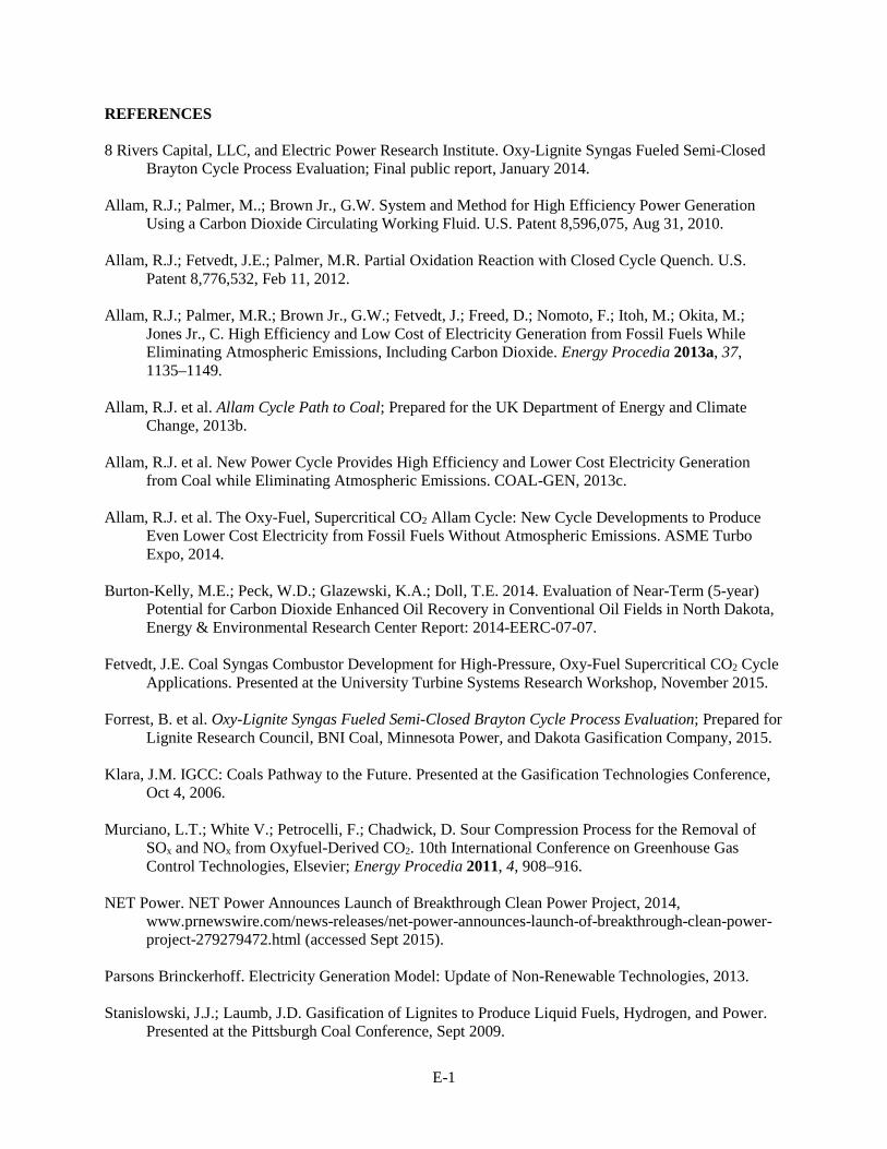
E-1
REFERENCES 8 Rivers Capital, LLC, and Electric Power Research Institute. Oxy-Lignite Syngas Fueled Semi-Closed
Brayton Cycle Process Evaluation; Final public report, January 2014. Allam, R.J.; Palmer, M..; Brown Jr., G.W. System and Method for High Efficiency Power Generation
Using a Carbon Dioxide Circulating Working Fluid. U.S. Patent 8,596,075, Aug 31, 2010. Allam, R.J.; Fetvedt, J.E.; Palmer, M.R. Partial Oxidation Reaction with Closed Cycle Quench. U.S.
Patent 8,776,532, Feb 11, 2012. Allam, R.J.; Palmer, M.R.; Brown Jr., G.W.; Fetvedt, J.; Freed, D.; Nomoto, F.; Itoh, M.; Okita, M.;
Jones Jr., C. High Efficiency and Low Cost of Electricity Generation from Fossil Fuels While Eliminating Atmospheric Emissions, Including Carbon Dioxide. Energy Procedia 2013a, 37, 1135–1149.
Allam, R.J. et al. Allam Cycle Path to Coal; Prepared for the UK Department of Energy and Climate
Change, 2013b. Allam, R.J. et al. New Power Cycle Provides High Efficiency and Lower Cost Electricity Generation
from Coal while Eliminating Atmospheric Emissions. COAL-GEN, 2013c. Allam, R.J. et al. The Oxy-Fuel, Supercritical CO2 Allam Cycle: New Cycle Developments to Produce
Even Lower Cost Electricity from Fossil Fuels Without Atmospheric Emissions. ASME Turbo Expo, 2014.
Burton-Kelly, M.E.; Peck, W.D.; Glazewski, K.A.; Doll, T.E. 2014. Evaluation of Near-Term (5-year)
Potential for Carbon Dioxide Enhanced Oil Recovery in Conventional Oil Fields in North Dakota, Energy & Environmental Research Center Report: 2014-EERC-07-07.
Fetvedt, J.E. Coal Syngas Combustor Development for High-Pressure, Oxy-Fuel Supercritical CO2 Cycle
Applications. Presented at the University Turbine Systems Research Workshop, November 2015. Forrest, B. et al. Oxy-Lignite Syngas Fueled Semi-Closed Brayton Cycle Process Evaluation; Prepared for
Lignite Research Council, BNI Coal, Minnesota Power, and Dakota Gasification Company, 2015. Klara, J.M. IGCC: Coals Pathway to the Future. Presented at the Gasification Technologies Conference,
Oct 4, 2006. Murciano, L.T.; White V.; Petrocelli, F.; Chadwick, D. Sour Compression Process for the Removal of
SOx and NOx from Oxyfuel-Derived CO2. 10th International Conference on Greenhouse Gas Control Technologies, Elsevier; Energy Procedia 2011, 4, 908–916.
NET Power. NET Power Announces Launch of Breakthrough Clean Power Project, 2014,
www.prnewswire.com/news-releases/net-power-announces-launch-of-breakthrough-clean-power-project-279279472.html (accessed Sept 2015).
Parsons Brinckerhoff. Electricity Generation Model: Update of Non-Renewable Technologies, 2013. Stanislowski, J.J.; Laumb, J.D. Gasification of Lignites to Produce Liquid Fuels, Hydrogen, and Power.
Presented at the Pittsburgh Coal Conference, Sept 2009.

E-2
Toshiba. Toshiba Signs Agreement to Develop Next Generation Thermal Power System with NET Power, Shaw Group and Exelon, 2012, www.toshiba.co.jp/about/press/2012_06/pr1502.htm (accessed Sept 2015).
U.S. Department of Energy. Carbon Capture Technology Program Plan. Clean Coal Research Program;
January 2013. U.S. Environmental Protection Agency. Carbon Pollution Emission Guidelines for Existing Stationary
Sources: Electric Utility Generating Units; Final Rule; 40 CFR Part 60. Vol. 80, No. 205, October 23, 2015.
White, V.; Torrente-Murciano, L.; Sturgeon, D.; Chadwick, D. Purification of Oxyfuel-Derived CO2;
International Journal of Greenhouse Gas Control; 4, 2010, 137–142.