application guide / installation … fts200 description: tandem axle system – standard fit...
TRANSCRIPT

Item: FTS200
Description: Tandem Axle System – Standard Fit
APPLICATION GUIDE / INSTALLATION INSTRUCTIONS / OWNER’S MANUAL
APPLICATION GUIDEThe Flying Tiger Air Ride Suspension can be installed on most Tandem Axle Recreation Vehicle Trailers and Travel Trailers and most leaf spring suspension trailers. Please reference the following information to determine compatibility with your Coach/Trailer. *This Kit Will Not Fit Leeland Jake Plate Style Frames.
Standard Installation Requirements
Leeland Jake Plate Style Frame
Before any disassembly be sure your trailer meets the following requirements:
2” or Greater Shackle Length (Hole To Hole)
Standard Center Hanger (See Figure 2) If the center hanger has a cross tube, the tube must be removed.
Minimum of 14” From Center Hanger Hole To Ground (See Figure 1)
Must Use Standard 1¾” Wide Leaf Springs
Shackle
Figure 1
Center Hanger
Figure 2
INSTALLATION INSTRUCTIONSInstallation of the Flying Tiger Suspension System requires removing the leaf spring equalizer from the OEM suspension. The use of shock absorbers in conjunction with the Flying Tiger Suspension System is strongly recommended. If the Coach/Trailer is not equipped with shock absorbers, please refer to the trailer manufacturer for information on the shock absorbers and/or the mountings available for the particular trailer. DO NOT MOUNT SHOCKS TO THE FLYING TIGER UNIT ITSELF.
Safety Precautions:Make sure the vehicle is properly supported before performing any maintenance or repair work. Follow the vehicle manufacturer’s recommendation for safely lifting and supporting the unit.
Read all instructions before attempting to install this product.
Cequent Towing Products47774 W. Anchor Court
Plymouth, MI 48170Phone: 866-352-7340
www.fifthgear.usFTS200IN REV. A 07/14/08 PCN11205
LITHO IN USA CEQUENT TOWING PRODUCTS Page 1

APPLICATION GUIDE / INSTALLATION INSTRUCTIONS / OWNER’S MANUALItem: FTS200
Description: Tandem Axle System – Standard Fit
DISASSEMBLY*It may be easier to complete one side (Disassembly & Installation) then move to the other.
1. With the vehicle raised by the frame and supported so the tires just clear the ground, remove wheels/tires from the axles. (See Picture 1)
2. Disconnect any electrical wiring or hydraulic brake lines from the axles to avoid damage. (See Picture 2)
3. Place floor or bottle jacks under each axle. Lift both axles slightly so that the shackle link bolts can be driven out with a hammer. Remove existing spring mounting bolts, shackle link bolts, and center link. (See Pictures 3 & 4)
4. Remove OE plastic Bushings from leaf spring eyes. This is easiest with a punch or blunt object and hammer. (See Picture 5) These Will be replaced with new premium Bronze bushings.
5. Maintain jacks under the axles for re-assembly.
Picture 1
Picture 2
Remove Existing Bolts Remove Existing Bolts
Picture 4 Picture 3
FTS200IN REV. A 07/14/08 PCN11205LITHO IN USA CEQUENT TOWING PRODUCTS Page 2
Cequent Towing Products47774 W. Anchor Court
Plymouth, MI 48170Phone: 866-352-7340
www.fifthgear.us
Remove Existing Bushings (2 Per Spring)
Picture 5
Item: FTS200
Description: Tandem Axle System – Standard Fit
APPLICATION GUIDE / INSTALLATION INSTRUCTIONS / OWNER’S MANUAL
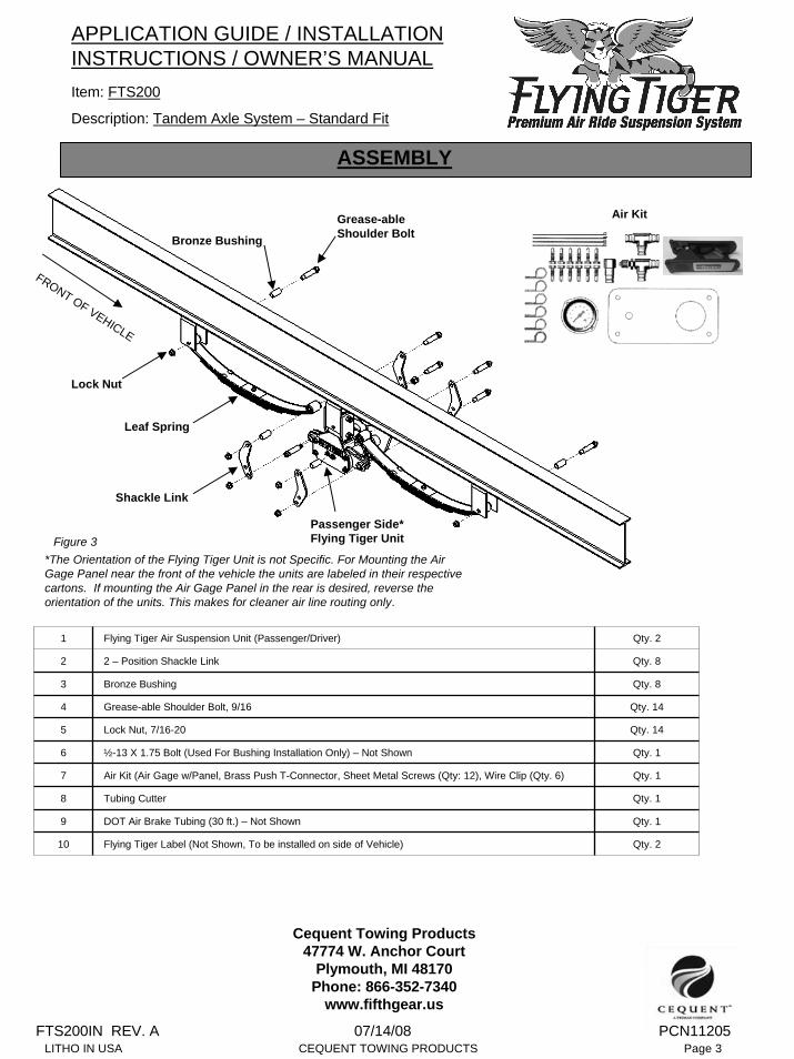
ASSEMBLY
FRONT OF VEHICLE
Lock Nut
Bronze Bushing
Grease-able Shoulder Bolt
Leaf Spring
Shackle Link
Passenger Side* Flying Tiger Unit
*The Orientation of the Flying Tiger Unit is not Specific. For Mounting the Air Gage Panel near the front of the vehicle the units are labeled in their respective cartons. If mounting the Air Gage Panel in the rear is desired, reverse the orientation of the units. This makes for cleaner air line routing only.
Air Kit
Figure 3
1 Flying Tiger Air Suspension Unit (Passenger/Driver) Qty. 2
2 2 – Position Shackle Link Qty. 8
3 Bronze Bushing Qty. 8
5 Lock Nut, 7/16-20 Qty. 14
6 ½-13 X 1.75 Bolt (Used For Bushing Installation Only) – Not Shown Qty. 1
8 Tubing Cutter Qty. 1
7 Air Kit (Air Gage w/Panel, Brass Push T-Connector, Sheet Metal Screws (Qty: 12), Wire Clip (Qty. 6) Qty. 1
9 DOT Air Brake Tubing (30 ft.) – Not Shown Qty. 1
10 Flying Tiger Label (Not Shown, To be installed on side of Vehicle) Qty. 2
4 Grease-able Shoulder Bolt, 9/16 Qty. 14
Cequent Towing Products47774 W. Anchor Court
Plymouth, MI 48170Phone: 866-352-7340
www.fifthgear.us
FTS200IN REV. A 07/14/08 PCN11205LITHO IN USA CEQUENT TOWING PRODUCTS Page 3

APPLICATION GUIDE / INSTALLATION INSTRUCTIONS / OWNER’S MANUALItem: FTS200
Description: Tandem Axle System – Standard Fit
FTS200IN REV. A 07/14/08 PCN11205LITHO IN USA CEQUENT TOWING PRODUCTS Page 4
Cequent Towing Products47774 W. Anchor Court
Plymouth, MI 48170Phone: 866-352-7340
www.fifthgear.us
ASSEMBLY
1. Do Not remove the clamp brackets or clamp bracket bolts (The bolts need to be loose and should come this way from the factory. Remove the mounting bolt. (See Figure 4) Install The Flying Tiger unit into the frame hanger. (Figure 5) Lifting the unit into position with a floor jack may be advantageous as the unit is heavy.
Clamp Brackets
Mounting BoltThe Unit Can be mounted in 2 positions:
Position 1: Use This Position In Most Cases. Install the mounting bolt in the bottom hole of the unit while positioned in the frame hanger.
Position 2: Use this position with short center hanger brackets that will not accept the unit in position 1. This position may also be used to increase the ride height of the vehicle by approximately ¾”-1” if this is desired.
Position 1
Position 2
Figure 5
Figure 4
Example of Position 1
NOTE: In specific cases where the side clamping plates cannot be used with a non-standard size center hanger, an alternative mounting is possible. If the unit will fit inside the center hanger and the hanger is tall enough, the unit may be mounted by removing the clamp brackets if (2) mounting bolts are used. (An additional pair of 9/16” -18 X 3” GR 8 bolts with nylon locknuts will be needed) It may be necessary to drill an additional hole in the center hanger corresponding with the hole shown for position 2 above.
2. Once the unit is in place, install the mounting bolt. Starting with the bottom clamp bracket bolt, torque both clamp bracket bolts to 100 ft-lbs. Next, torque the mounting bolt to 100 ft-lbs. (In the afore mentioned case where the clamp brackets are not used, torque (2) mounting bolts to 100 ft-lbs.) Check that no water lines, electrical lines, etc. interfere with the suspension unit. Attempt to relocate any items that interfere with the operation of the suspension unit.
3. Install bronze bushings in the leaf spring eyes. Using a lithium spray grease will ease the installation of the bushings. The included ½-13 X 1.75” bolt is supplied to drive the bushings in place without damage to the bushings. DO NOT hit the bushings directly with a hammer as this will damage the bushings. Insert the bushing in the spring eye, insert the ½-13 bolt into the bushing, drive the bushing into place by tapping the bolt with a hammer. (See Picture 6 & 7)
Picture 6
Picture 7

APPLICATION GUIDE / INSTALLATION INSTRUCTIONS / OWNER’S MANUALItem: FTS200
Description: Tandem Axle System – Standard Fit
ASSEMBLY
4. Install the grease-able bolts with the grease fittings is to the inside of the frame, this will allow access to the grease fitting without removal of the tires. (See Figure 5) Using a hammer and piece of tubing or ½” drive extension and hammer, drive the bolt in until the head is seated against the frame hanger and/or shackle link surface. Tighten the nut until it bottoms out on the bolt shoulder, 45-55 ft-lbs.
5. When installing the shackle links there are 2 positions available. Position 1 & Position 2, refer to figure 6 to choose the position right for your application. Lift the axles with the jacks into their normal operating position so that the spring eyes are higher than the eyes on the Flying Tiger unit. Attach the new shackle link assemblies, shackle links, grease-able bolts and mounting nuts. Tighten mounting nuts to 45-55 ft-lbs making sure the bolt head is seated against the shackle link surface.
6. Once both sides are complete, reinstall the wheels/tires and torque to the vehicle manufacturer’s recommendations.
7. Grease all shoulder bolts with standard automotive axle grease or similar wheel bearing grease.
Figure 6
FTS200IN REV. A 07/14/08 PCN11205LITHO IN USA CEQUENT TOWING PRODUCTS Page 5
Cequent Towing Products47774 W. Anchor Court
Plymouth, MI 48170Phone: 866-352-7340
www.fifthgear.us
Figure 7
Position 1: This position is used if shorter shackle links were removed from the vehicle or to raise the vehicle ride height.
Position 2: This position is used if longer shackle links (3” or Greater) were removed from the vehicle or to lower the vehicle ride height.
AIR KIT INSTALLATION
The first step in installing the air kit is to determine the location of the air fill access valve/air pressure gage. It is recommended to install the fill/gage panel on the passenger side of the coach; this provides safety while checking the air pressure on the side of the road, however this can be mounted in many locations on the vehicle. Some prefer to mount this panel inside of a compartment or near the entry/exit of the coach for quick inspection of air pressure level. Be sure to check for potential interference andpossible damage to other components before cutting any access/installation holes.
Figure 8Basic Air Line Routing
(Gage/Fill Shown on Driver Side)
APPLICATION GUIDE / INSTALLATION INSTRUCTIONS / OWNER’S MANUALItem: FTS200
Description: Tandem Axle System – Standard Fit
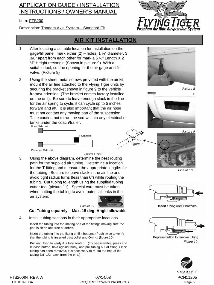
AIR KIT INSTALLATION1. After locating a suitable location for installation on the
gage/fill panel: mark either (2) – holes, 1 ¾” diameter, 3 3/8” apart from each other /or mark a 5 ½” Length X 2 ½” Height rectangle (Shown in picture 9) With a suitable tool, cut the opening for the air gage and fill valve. (Picture 8)
2. Using the sheet metal screws provided with the air kit, mount the air line attached to the Flying Tiger units by securing the bracket shown in figure 9 to the vehicle frame/underside. (The bracket comes factory installed on the unit). Be sure to leave enough slack in the line for the air spring to cycle, it can cycle up to 5 inches forward and aft. It is also important that the air hose must not contact any moving part of the suspension. Take caution not to run the screws into any electrical or tanks under the coach/trailer.
3. Using the above diagram, determine the best routing path for the supplied air tubing. Determine a location for the T-fitting and measure the appropriate lengths for the tubing. Be sure to leave slack in the air line and avoid tight radius turns (less than 6”) while routing the tubing. Cut tubing to length using the supplied tubing cutter tool (picture 11). Special care must be taken when cutting the tubing to avoid potential leaks in the air system:
Cut Tubing squarely – Max. 15 deg. Angle allowable
4. Install tubing sections in their appropriate locations.Insert the tubing into the mating port of the fittings making sure the port is clean and free of debris.
Insert the tubing into the fitting until it bottoms (Push twice to verify that the tubing is inserted past collet and O-ring. (figure 10)
Pull on tubing to verify it is fully seated. (To disassemble, press and release button, hold against body, and pull tubing out of fitting. Once tubing has been removed, it is necessary to re-cut the end of the tubing 3/8”-1/2” back from the end.)
Picture 8
Picture 9
Picture 10
Picture 11
Figure 9
Driver Side Unit
Passenger Side Unit
T-Connector
Display/Fill Panel
FTS200IN REV. A 07/14/08 PCN11205LITHO IN USA CEQUENT TOWING PRODUCTS Page 6
Figure 10

FTS200IN REV. A 07/14/08 PCN11205LITHO IN USA CEQUENT TOWING PRODUCTS Page 7
Item: FTS200
Description: Tandem Axle System – Standard Fit
APPLICATION GUIDE / INSTALLATION INSTRUCTIONS / OWNER’S MANUAL
AIR KIT INSTALLATION5. Install the supplied wire clips and self drilling screws,
position the clips in a manner which will keep the airlines tight to the belly of the coach. Take care not to leave the airline in a position to be snagged by road debris and/or interfere with the moving components of the coach/trailer. (Picture 12)
6. Connect the airline to the gage/fill panel (Picture 13), following the fitting guidelines from instruction #4. Install the 4 self drilling screws in holes provided in the panel. (Picture 14).
7. Install the provided decals on the coach, placement of the decal is suggested over the wheel well on both sides of the coach/trailer. (Picture 15)
Picture 12
DecalPicture 13
Picture 14Picture 15
OWNER’S MANUAL INSTALLATION
AIR PRESSURE ADJUSTMENTUnlike most air suspension products on the market, adjusting the air bag pressure will not raise/lower the ride height of the vehicle.
To set the pressure first inflate to 100 psi (this seats the air fittings). Then reduce the pressure to, 5 PSI per 1,000 lbs. of coach weight
ex: for a coach weight of 15,000 lbs, the initial pressure setting is calculated by 15000 ÷ 1000 = 15 X 5 = 75 psi.
This will vary depending on the loading of the coach and should be adjusted according to personnel preference. If you experience a harsh ride reduce the pressure of the system. If you feel that the ride is too soft, add air until the ride is satisfactory.
APPLICATION GUIDE / INSTALLATION INSTRUCTIONS / OWNER’S MANUALItem: FTS200
Description: Tandem Axle System – Standard Fit
OWNER’S MANUAL INSTALLATION
HELPFUL HINTSIf the system is leaking air, set the pressure to 50 psi. Using a solution of dish soap and water, apply solution to all fittings. Inspect for the formation of bubbles. If the leak is at one of the push in fittings attempt to re-cut the air line according to the Instructions and re-install the connection. Re-apply the soap solution to confirm the leak is no longer present. If the leak cannot be traced to a fitting connection, the air gage and the fill valve are the most likely pneumatic parts to leak.
The system may loose pressure over an extended time period and this is considered normal, however leaks which loose pressure in just a few hours should be addressed.
The suspension can operate without any air in the system in cases where travel is necessary. It should be noted that prolonged use in this condition can result in accelerated ware to the stop plates and the performance benefits of the suspension will not apply when there is no air in the system.
The air spring may return to a position other than center, this is not abnormal.
There is no lubrication required to the Flying Tiger Suspension unit, however the grease-able bolts should be part of the routine maintenance on the trailer.
There are three natural factors that will affect the air pressure in the system; Temperature, Altitude, and Loading of the coach. A change in altitude of 3000 – 4000 ft. or more, a change in temperature of 40 deg or more, and/or 500 lbs change in the loading of the coach could result in a 2-5 psi. reading of the system pressure. If these conditions are temporary, no adjustment to the air pressure may be required.
Cequent Towing Products will replace FREE OF CHARGE any part which proves defective in material or workmanship when presented to any Cequent Towing Products dealer (consult local telephone directory) or Cequent Towing Products warehouse, or when returned to the factory, TRANSPORTATION CHARGES PREPAID, at the address below. THIS WARRANTY IS LIMITED TO DEFECTIVE PARTS REPLACEMENT ONLY. LABOR CHARGES AND/OR DAMAGE INCURRED IN INSTALLATION OR REPLACEMENT AS WELL AS INCIDENTAL AND CONSEQUENTIAL DAMAGES CONNECTED THEREWITH ARE EXCLUDED.
Some states do not allow the exclusion or limitation of incidental or consequential damages, so the above limitation or exclusion may not apply to you.
Any damage to the product as a result of misuse, abuse, neglect, accident, improper installation, or any use violative of the instruction furnished by us WILL VOID THE WARRANTY.
This warranty gives you specific legal rights, and you may also have other rights which vary from state to state. In the event of a problem with warranty service or performance, you may be able to go to a small claims court, a state court, or a federal district court.
ONE YEAR LIMITED WARRANTY
FTS200IN REV. A 07/14/08 PCN11205LITHO IN USA CEQUENT TOWING PRODUCTS Page 8
Cequent Towing Products47774 W. Anchor Court
Plymouth, MI 48170Phone: 866-352-7340
www.fifthgear.us