application example 04/2016 communication …...application example 04/2016 communication between...
TRANSCRIPT

https://support.industry.siemens.com/cs/ww/en/view/109481157
Application Example 04/2016
Communication between HMI and Frequency Converter Basic Panel, Comfort Panel, Runtime Advanced, SINAMICS G120
Warranty and Liability
Communication HMI FU Entry ID: 109481157, V1.0, 04/2016 2
S
iem
en
s A
G 2
01
6 A
ll ri
gh
ts r
ese
rve
d
Warranty and Liability
Note The Application Examples are not binding and do not claim to be complete with regard to configuration, equipment or any contingencies. The Application Examples do not represent customer-specific solutions. They are only intended to provide support for typical applications. You are responsible for the correct operation of the described products. These Application Examples do not relieve you of the responsibility of safely and professionally using, installing, operating and servicing equipment. When using these Application Examples, you recognize that we cannot be made liable for any damage/claims beyond the liability clause described. We reserve the right to make changes to these Application Examples at any time and without prior notice. If there are any deviations between the recommendations provided in this Application Example and other Siemens publications – e.g. Catalogs – the contents of the other documents shall have priority.
We do not accept any liability for the information contained in this document.
Any claims against us – based on whatever legal reason – resulting from the use of the examples, information, programs, engineering and performance data etc., described in this Application Example shall be excluded. Such an exclusion shall not apply in the case of mandatory liability, e.g. under the German Product Liability Act (“Produkthaftungsgesetz”), in case of intent, gross negligence, or injury of life, body or health, guarantee for the quality of a product, fraudulent concealment of a deficiency or breach of fundamental contractual obligations (“wesentliche Vertragspflichten”). The compensation for damages due to a breach of a fundamental contractual obligation is, however, limited to the foreseeable damage, typical for the type of contract, except in the event of intent or gross negligence or injury to life, body or health. The above provisions do not imply a change of the burden of proof to your detriment.
Any form of duplication or distribution of these Application Examples or excerpts hereof is prohibited without the expressed consent of Siemens AG.
Security informa-tion
Siemens provides products and solutions with industrial security functions that support the secure operation of plants, systems, machines and networks. In order to protect plants, systems, machines and networks against cyber threats, it is necessary to implement – and continuously maintain – a holistic, state-of-the-art industrial security concept. Siemens’ products and solutions only form one element of such a concept. Customer is responsible to prevent unauthorized access to its plants, systems, machines and networks. Systems, machines and components should only be connected to the enterprise network or the internet if and to the extent necessary and with appropriate security measures (e.g. use of firewalls and network segmentation) in place. Additionally, Siemens’ guidance on appropriate security measures should be taken into account. For more information about industrial security, please visit http://www.siemens.com/industrialsecurity.
Siemens’ products and solutions undergo continuous development to make them more secure. Siemens strongly recommends to apply product updates as soon as available and to always use the latest product versions. Use of product versions that are no longer supported, and failure to apply latest updates may increase customer’s exposure to cyber threats. To stay informed about product updates, subscribe to the Siemens Industrial Security RSS Feed under http://www.siemens.com/industrialsecurity.

Table of Contents
Communication HMI FU Entry ID: 109481157, V1.0, 04/2016 3
S
iem
en
s A
G 2
01
6 A
ll ri
gh
ts r
ese
rve
d
Table of Contents Warranty and Liability ................................................................................................. 2
1 Task ..................................................................................................................... 4
1.1 Overview............................................................................................... 4
2 Solution............................................................................................................... 5
2.1 Setup .................................................................................................... 5 2.2 Hardware and software components ................................................... 6 2.2.1 Validity .................................................................................................. 6 2.2.2 Components used ................................................................................ 6
3 Basics ................................................................................................................. 7
3.1 Access to the converter parameters .................................................... 7
4 Mode of Operation ............................................................................................. 8
4.1 Creating error messages ...................................................................... 8 4.2 Configuring the frequency converter .................................................... 8
5 Configuration and settings of the HMI operator panel .................................. 9
5.1 Setting the IP address at the panel ...................................................... 9 5.2 Creating a connection in the HMI project ........................................... 11 5.3 Creating the alarm view ...................................................................... 13 5.4 SINAMICS XML Parser ...................................................................... 14 5.5 Configuring message text................................................................... 15 5.6 Configuring parameter access in the HMI .......................................... 20
6 Configuration and settings of the drive ........................................................ 21
6.1 Adding the frequency converter to the project ................................... 21 6.2 Setting the Ethernet address .............................................................. 22 6.3 Commissioning wizard ....................................................................... 23 6.4 Parameterizing converter settings ...................................................... 28
7 Operating the Application ............................................................................... 30
7.1 Commissioning the example project .................................................. 30 7.2 Operating the example project ........................................................... 30
8 Further Notes, Tips & Tricks, etc. .................................................................. 32
9 Alternative ........................................................................................................ 33
10 Links & Literature ............................................................................................ 34
11 History............................................................................................................... 34
1 Task
1.1 Overview
Communication HMI FU Entry ID: 109481157, V1.0, 04/2016 4
S
iem
en
s A
G 2
01
6 A
ll ri
gh
ts r
ese
rve
d
1 Task
1.1 Overview
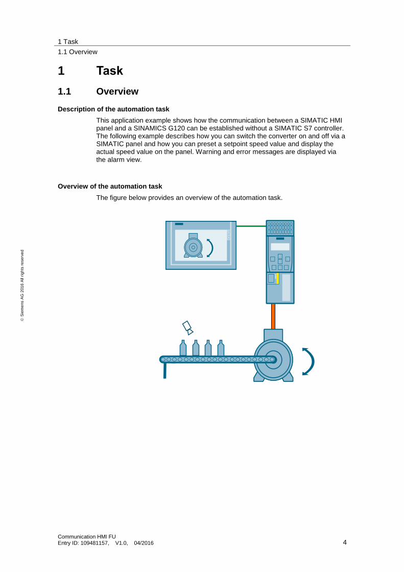
Description of the automation task
This application example shows how the communication between a SIMATIC HMI panel and a SINAMICS G120 can be established without a SIMATIC S7 controller. The following example describes how you can switch the converter on and off via a SIMATIC panel and how you can preset a setpoint speed value and display the actual speed value on the panel. Warning and error messages are displayed via the alarm view.
Overview of the automation task
The figure below provides an overview of the automation task.

2 Solution
2.1 Setup
Communication HMI FU Entry ID: 109481157, V1.0, 04/2016 5
S
iem
en
s A
G 2
01
6 A
ll ri
gh
ts r
ese
rve
d
2 Solution
2.1 Setup
Schematic layout
Figure 2-1
PROFINET IE
Example
You want to achieve the following via the SIMATIC panel:
Display warning and error messages via the alarm view
Switch the converter on and off
Specify a setpoint value
Display the actual value and the status
2 Solution
2.2 Hardware and software components
Communication HMI FU Entry ID: 109481157, V1.0, 04/2016 6
S
iem
en
s A
G 2
01
6 A
ll ri
gh
ts r
ese
rve
d
Assumed knowledge
For the implementation of the solution described in this document, basic knowledge in the following topics is assumed:
Automation technology
Commissioning of the SINAMICS G120 frequency converter
2.2 Hardware and software components
2.2.1 Validity
This application is valid for
TIA Portal V13 SP1 Update 1
2.2.2 Components used
The application was created with the following components:
Hardware components
Table 2-1
Component Qty Article number Note
SINAMICS Control Unit CU240E-2 PN-F
1 6SL3244-0BB13-1FA0 Firmware >= V4.7
SINAMICS PM240 1 6SL3224-0BE13-7UA0
TP900 Comfort 1 6AV2 124-0JC01-0AX0 As an alternative, you can also use other Basic Panels, Comfort Panels or Advanced PC Stations.
Low-voltage motor 1 1LA7060-4AB10-Z
Software components
Table 2-2
Component Qty Article number Note
SINAMICS Startdrive V13
1 6SL3072-4DA02-0XG0
WinCC Runtime Advanced V13
1 6AV2104-....3-0
Example files and projects
The following list includes all files and projects that are used in this example.
Table 2-3
Component Note
109481157_HMI_FU_CODE_v13.zip This zip file contains the WinCC project.
109481157_HMI_FU_DOKU_v13_e.pdf This document.
3 Basics
3.1 Access to the converter parameters
Communication HMI FU Entry ID: 109481157, V1.0, 04/2016 7
S
iem
en
s A
G 2
01
6 A
ll ri
gh
ts r
ese
rve
d
3 Basics
3.1 Access to the converter parameters
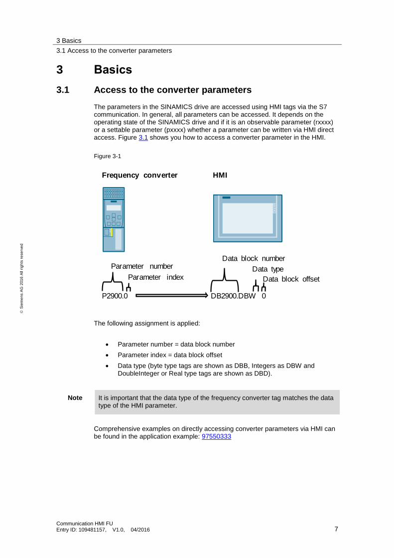
The parameters in the SINAMICS drive are accessed using HMI tags via the S7 communication. In general, all parameters can be accessed. It depends on the operating state of the SINAMICS drive and if it is an observable parameter (rxxxx) or a settable parameter (pxxxx) whether a parameter can be written via HMI direct access. Figure 3.1 shows you how to access a converter parameter in the HMI.
Figure 3-1
Parameter number
Parameter index
P2900.0 DB2900.DBW 0
Data block offset
Data type
Data block number
Frequency converter HMI
The following assignment is applied:
Parameter number = data block number
Parameter index = data block offset
Data type (byte type tags are shown as DBB, Integers as DBW and DoubleInteger or Real type tags are shown as DBD).
Note It is important that the data type of the frequency converter tag matches the data type of the HMI parameter.
Comprehensive examples on directly accessing converter parameters via HMI can be found in the application example: 97550333
4 Mode of Operation
4.1 Creating error messages
Communication HMI FU Entry ID: 109481157, V1.0, 04/2016 8
S
iem
en
s A
G 2
01
6 A
ll ri
gh
ts r
ese
rve
d
4 Mode of Operation
4.1 Creating error messages
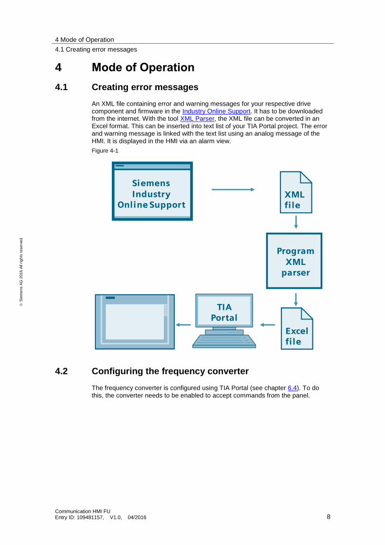
An XML file containing error and warning messages for your respective drive component and firmware in the Industry Online Support. It has to be downloaded from the internet. With the tool XML Parser, the XML file can be converted in an Excel format. This can be inserted into text list of your TIA Portal project. The error and warning message is linked with the text list using an analog message of the HMI. It is displayed in the HMI via an alarm view.
Figure 4-1
XMLfile
ProgramXML
parser
SiemensIndustry
Online Support
Excelfile
TIA Portal
4.2 Configuring the frequency converter
The frequency converter is configured using TIA Portal (see chapter 6.4). To do this, the converter needs to be enabled to accept commands from the panel.
5 Configuration and settings of the HMI operator panel
5.1 Setting the IP address at the panel
Communication HMI FU Entry ID: 109481157, V1.0, 04/2016 9
S
iem
en
s A
G 2
01
6 A
ll ri
gh
ts r
ese
rve
d
5 Configuration and settings of the HMI operator panel
5.1 Setting the IP address at the panel
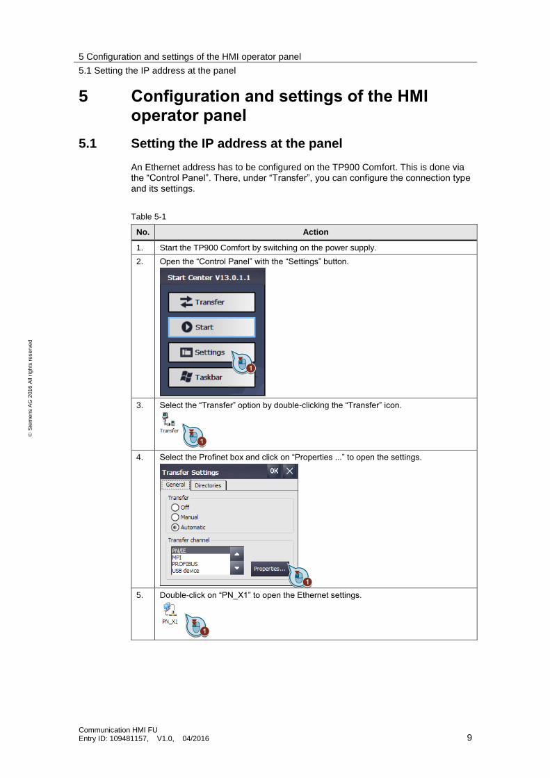
An Ethernet address has to be configured on the TP900 Comfort. This is done via the “Control Panel”. There, under “Transfer”, you can configure the connection type and its settings.
Table 5-1
No. Action
1. Start the TP900 Comfort by switching on the power supply.
2. Open the “Control Panel” with the “Settings” button.
3. Select the “Transfer” option by double-clicking the “Transfer” icon.
4. Select the Profinet box and click on “Properties ...” to open the settings.
5. Double-click on “PN_X1” to open the Ethernet settings.
5 Configuration and settings of the HMI operator panel
5.1 Setting the IP address at the panel
Communication HMI FU Entry ID: 109481157, V1.0, 04/2016 10
S
iem
en
s A
G 2
01
6 A
ll ri
gh
ts r
ese
rve
d
No. Action
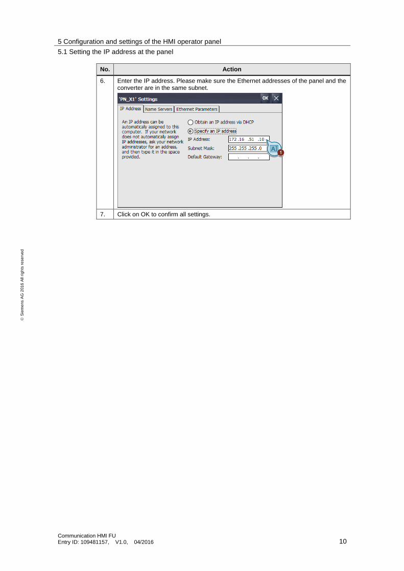
6. Enter the IP address. Please make sure the Ethernet addresses of the panel and the converter are in the same subnet.
7. Click on OK to confirm all settings.
5 Configuration and settings of the HMI operator panel
5.2 Creating a connection in the HMI project
Communication HMI FU Entry ID: 109481157, V1.0, 04/2016 11
S
iem
en
s A
G 2
01
6 A
ll ri
gh
ts r
ese
rve
d
5.2 Creating a connection in the HMI project
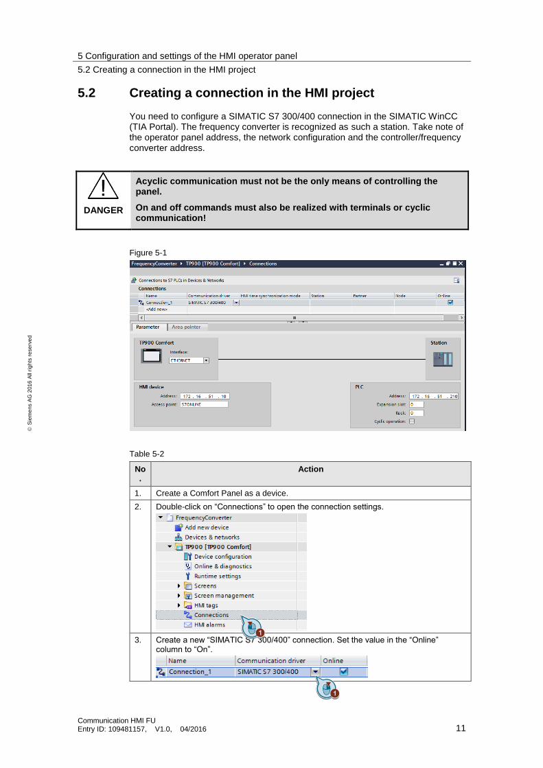
You need to configure a SIMATIC S7 300/400 connection in the SIMATIC WinCC (TIA Portal). The frequency converter is recognized as such a station. Take note of the operator panel address, the network configuration and the controller/frequency converter address.
DANGER
Acyclic communication must not be the only means of controlling the panel.
On and off commands must also be realized with terminals or cyclic communication!
Figure 5-1
Table 5-2
No.
Action
1. Create a Comfort Panel as a device.
2. Double-click on “Connections” to open the connection settings.
3. Create a new “SIMATIC S7 300/400” connection. Set the value in the “Online” column to “On”.
5 Configuration and settings of the HMI operator panel
5.2 Creating a connection in the HMI project
Communication HMI FU Entry ID: 109481157, V1.0, 04/2016 12
S
iem
en
s A
G 2
01
6 A
ll ri
gh
ts r
ese
rve
d
No.
Action
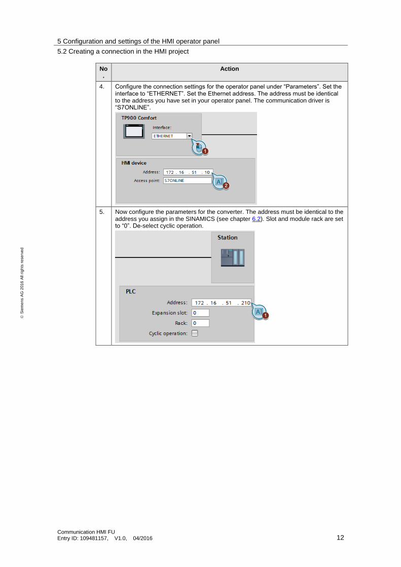
4. Configure the connection settings for the operator panel under “Parameters”. Set the interface to “ETHERNET”. Set the Ethernet address. The address must be identical to the address you have set in your operator panel. The communication driver is “S7ONLINE”.
5. Now configure the parameters for the converter. The address must be identical to the address you assign in the SINAMICS (see chapter 6.2). Slot and module rack are set to “0”. De-select cyclic operation.
5 Configuration and settings of the HMI operator panel
5.3 Creating the alarm view
Communication HMI FU Entry ID: 109481157, V1.0, 04/2016 13
S
iem
en
s A
G 2
01
6 A
ll ri
gh
ts r
ese
rve
d
5.3 Creating the alarm view
Table 5-3
No.
Action
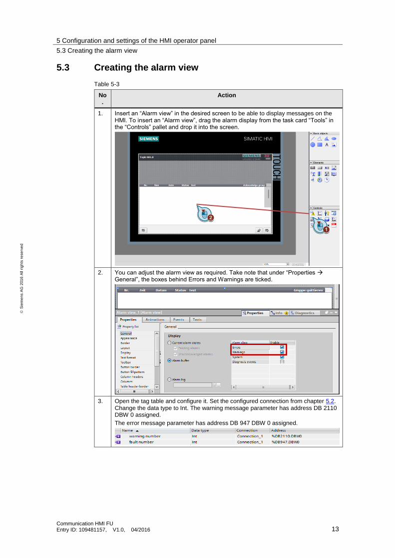
1. Insert an “Alarm view” in the desired screen to be able to display messages on the HMI. To insert an “Alarm view”, drag the alarm display from the task card “Tools” in the “Controls” pallet and drop it into the screen.
2. You can adjust the alarm view as required. Take note that under “Properties General”, the boxes behind Errors and Warnings are ticked.
3. Open the tag table and configure it. Set the configured connection from chapter 5.2. Change the data type to Int. The warning message parameter has address DB 2110 DBW 0 assigned.
The error message parameter has address DB 947 DBW 0 assigned.
5 Configuration and settings of the HMI operator panel
5.4 SINAMICS XML Parser
Communication HMI FU Entry ID: 109481157, V1.0, 04/2016 14
S
iem
en
s A
G 2
01
6 A
ll ri
gh
ts r
ese
rve
d
5.4 SINAMICS XML Parser
An XML file containing error and warning messages for your respective drive component and firmware in the Industry Online Support. For the SINAMICS Control Unit CU240E-2 PN-F firmware version 4.7 described in the application example, the error and warning messages can be found under entry ID: 92554110. With the tool XML Parser, the XML file can be converted in an Excel format. The following pages show how to transfer the errors and warnings to Excel format for a CU240E-2 PN-F.
Table 5-4
No. Action
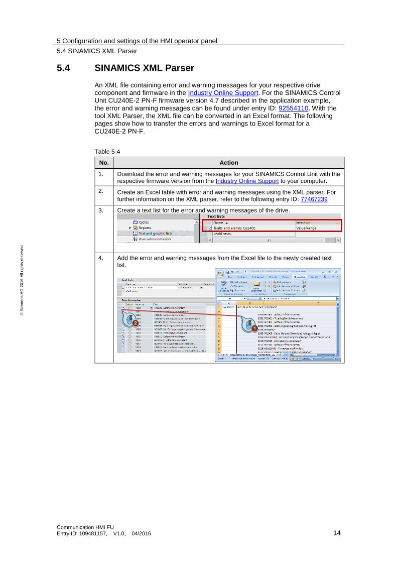
1. Download the error and warning messages for your SINAMICS Control Unit with the respective firmware version from the Industry Online Support to your computer.
2. Create an Excel table with error and warning messages using the XML parser. For further information on the XML parser, refer to the following entry ID: 77467239
3. Create a text list for the error and warning messages of the drive.
4. Add the error and warning messages from the Excel file to the newly created text list.
5 Configuration and settings of the HMI operator panel
5.5 Configuring message text
Communication HMI FU Entry ID: 109481157, V1.0, 04/2016 15
S
iem
en
s A
G 2
01
6 A
ll ri
gh
ts r
ese
rve
d
5.5 Configuring message text
It is possible to display a process value or an entry from a text list in an alarm view when an analog message arrives.
For further information on how to configure messages and alarms in WinCC (TIA Portal), refer to entry ID: 62121503
Table 5-5
No. Action
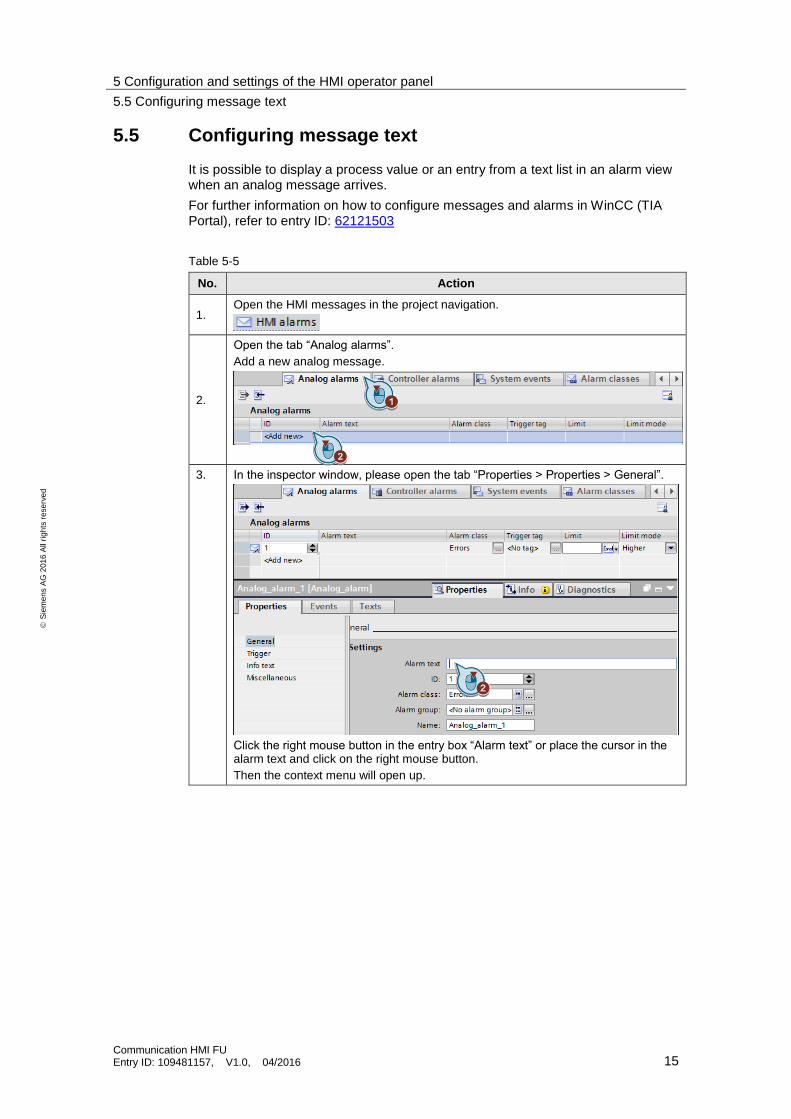
1. Open the HMI messages in the project navigation.
2.
Open the tab “Analog alarms”.
Add a new analog message.
3. In the inspector window, please open the tab “Properties > Properties > General”.
Click the right mouse button in the entry box “Alarm text” or place the cursor in the alarm text and click on the right mouse button.
Then the context menu will open up.
5 Configuration and settings of the HMI operator panel
5.5 Configuring message text
Communication HMI FU Entry ID: 109481157, V1.0, 04/2016 16
S
iem
en
s A
G 2
01
6 A
ll ri
gh
ts r
ese
rve
d
No. Action
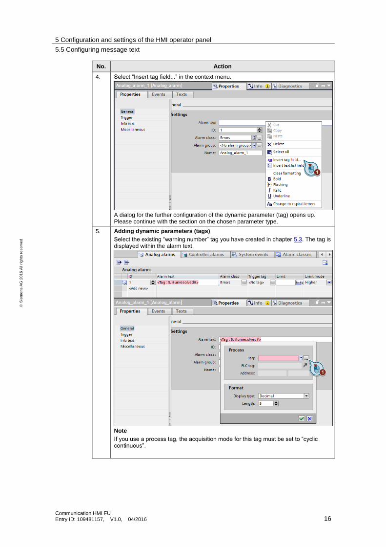
4. Select “Insert tag field...” in the context menu.
A dialog for the further configuration of the dynamic parameter (tag) opens up. Please continue with the section on the chosen parameter type.
5. Adding dynamic parameters (tags)
Select the existing “warning number” tag you have created in chapter 5.3. The tag is displayed within the alarm text.
Note
If you use a process tag, the acquisition mode for this tag must be set to “cyclic continuous”.
5 Configuration and settings of the HMI operator panel
5.5 Configuring message text
Communication HMI FU Entry ID: 109481157, V1.0, 04/2016 17
S
iem
en
s A
G 2
01
6 A
ll ri
gh
ts r
ese
rve
d
No. Action
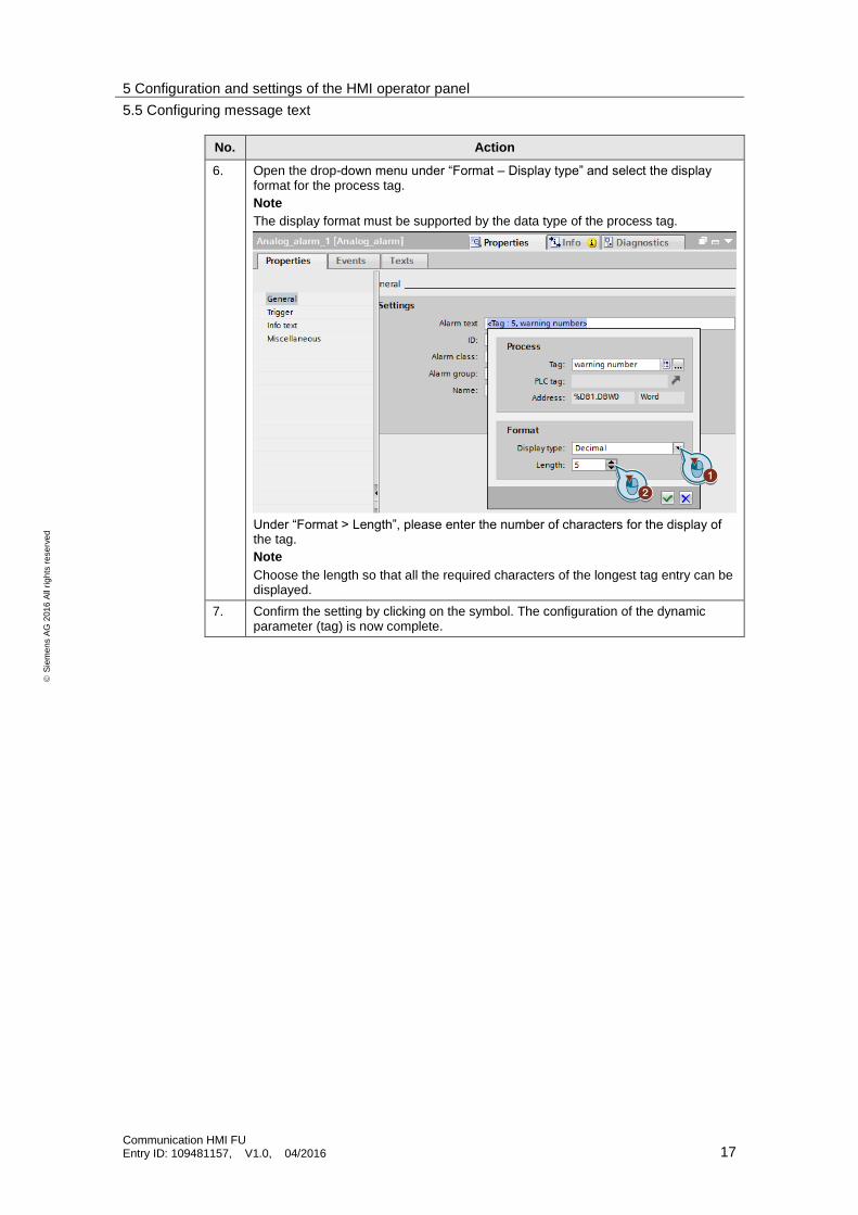
6. Open the drop-down menu under “Format – Display type” and select the display format for the process tag.
Note
The display format must be supported by the data type of the process tag.
Under “Format > Length”, please enter the number of characters for the display of the tag.
Note
Choose the length so that all the required characters of the longest tag entry can be displayed.
7. Confirm the setting by clicking on the symbol. The configuration of the dynamic parameter (tag) is now complete.
5 Configuration and settings of the HMI operator panel
5.5 Configuring message text
Communication HMI FU Entry ID: 109481157, V1.0, 04/2016 18
S
iem
en
s A
G 2
01
6 A
ll ri
gh
ts r
ese
rve
d
No. Action
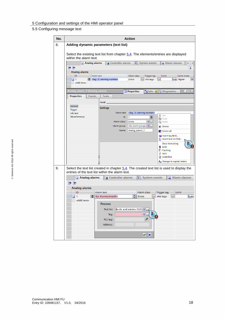
8. Adding dynamic parameters (text list)
Select the existing text list from chapter 5.4. The elements/entries are displayed within the alarm text.
9. Select the text list created in chapter 5.4. The created text list is used to display the entries of the text list within the alarm text.

5 Configuration and settings of the HMI operator panel
5.5 Configuring message text
Communication HMI FU Entry ID: 109481157, V1.0, 04/2016 19
S
iem
en
s A
G 2
01
6 A
ll ri
gh
ts r
ese
rve
d
No. Action
10. Select the existing “warning number” tag from chapter 5.3 for the text list. Confirm the setting by clicking on the symbol.
Note:
If you use a process tag as an index tag, the acquisition mode for this tag of this process tag must be set to “cyclic continuous”.
11. Select “warning number” as trigger tag. Enter 0 as a constant.
The configuration of the dynamic parameter (text list) is now complete.
12. Repeat the steps for the fault messages. Instead of the “warning number” tag, use the “fault number” tag to do this. The fault messages are also contained in the text list created in chapter 5.4.
5 Configuration and settings of the HMI operator panel
5.6 Configuring parameter access in the HMI
Communication HMI FU Entry ID: 109481157, V1.0, 04/2016 20
S
iem
en
s A
G 2
01
6 A
ll ri
gh
ts r
ese
rve
d
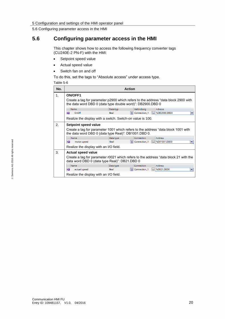
5.6 Configuring parameter access in the HMI
This chapter shows how to access the following frequency converter tags (CU240E-2 PN-F) with the HMI:
Setpoint speed value
Actual speed value
Switch fan on and off
To do this, set the tags to “Absolute access” under access type.
Table 5-6
No. Action
1. ON/OFF1
Create a tag for parameter p2900 which refers to the address “data block 2900 with the data word DBD 0 (data type double word)”: DB2900.DBD 0
Realize the display with a switch. Switch-on value is 100.
2. Setpoint speed value
Create a tag for parameter 1001 which refers to the address “data block 1001 with the data word DBD 0 (data type Real)”: DB1001.DBD 0.
Realize the display with an I/O field.
3. Actual speed value
Create a tag for parameter r0021 which refers to the address “data block 21 with the data word DBD 0 (data type Real)”: DB21.DBD 0
Realize the display with an I/O field.
6 Configuration and settings of the drive
6.1 Adding the frequency converter to the project
Communication HMI FU Entry ID: 109481157, V1.0, 04/2016 21
S
iem
en
s A
G 2
01
6 A
ll ri
gh
ts r
ese
rve
d
6 Configuration and settings of the drive
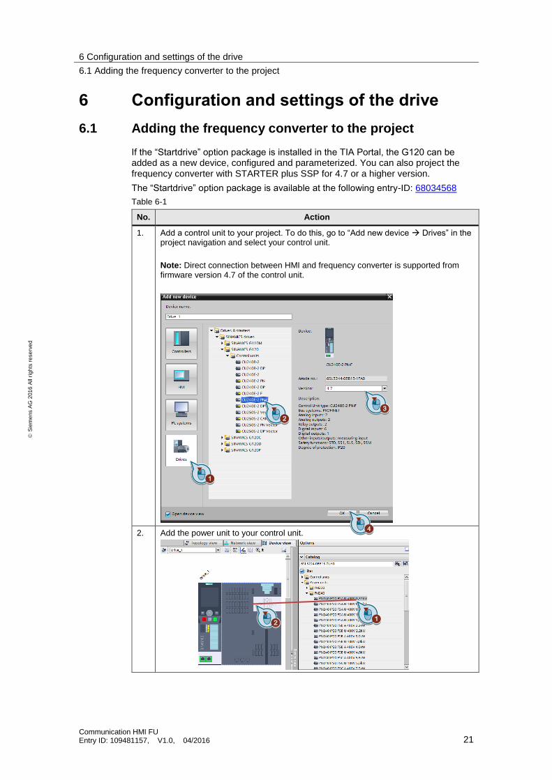
6.1 Adding the frequency converter to the project
If the “Startdrive” option package is installed in the TIA Portal, the G120 can be added as a new device, configured and parameterized. You can also project the frequency converter with STARTER plus SSP for 4.7 or a higher version.
The “Startdrive” option package is available at the following entry-ID: 68034568
Table 6-1
No. Action
1. Add a control unit to your project. To do this, go to “Add new device Drives” in the project navigation and select your control unit.
Note: Direct connection between HMI and frequency converter is supported from firmware version 4.7 of the control unit.
2. Add the power unit to your control unit.
6 Configuration and settings of the drive
6.2 Setting the Ethernet address
Communication HMI FU Entry ID: 109481157, V1.0, 04/2016 22
S
iem
en
s A
G 2
01
6 A
ll ri
gh
ts r
ese
rve
d
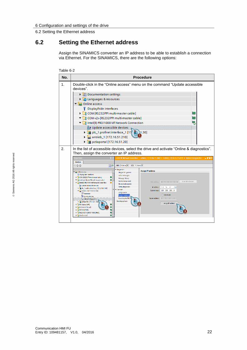
6.2 Setting the Ethernet address
Assign the SINAMICS converter an IP address to be able to establish a connection via Ethernet. For the SINAMICS, there are the following options:
Table 6-2
No. Procedure
1. Double-click in the “Online access” menu on the command “Update accessible devices”.
2. In the list of accessible devices, select the drive and activate “Online & diagnostics”. Then, assign the converter an IP address.
6 Configuration and settings of the drive
6.3 Commissioning wizard
Communication HMI FU Entry ID: 109481157, V1.0, 04/2016 23
S
iem
en
s A
G 2
01
6 A
ll ri
gh
ts r
ese
rve
d
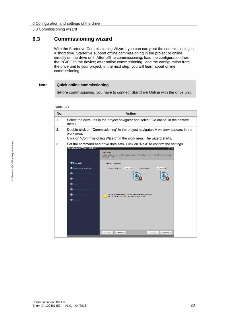
6.3 Commissioning wizard
With the Startdrive Commissioning Wizard, you can carry out the commissioning in a short time. Startdrive support offline commissioning in the project or online directly on the drive unit. After offline commissioning, load the configuration from the PG/PC to the device; after online commissioning, load the configuration from the drive unit to your project. In the next step, you will learn about online commissioning.
Note Quick online commissioning
Before commissioning, you have to connect Startdrive Online with the drive unit.
Table 6-3
No. Action
1. Select the drive unit in the project navigator and select “Go online” in the context menu.
2. Double-click on “Commissioning” in the project navigator. A window appears in the work area.
Click on “Commissioning Wizard” in the work area. The wizard starts.
3. Set the command and drive data sets. Click on “Next” to confirm the settings.
6 Configuration and settings of the drive
6.3 Commissioning wizard
Communication HMI FU Entry ID: 109481157, V1.0, 04/2016 24
S
iem
en
s A
G 2
01
6 A
ll ri
gh
ts r
ese
rve
d
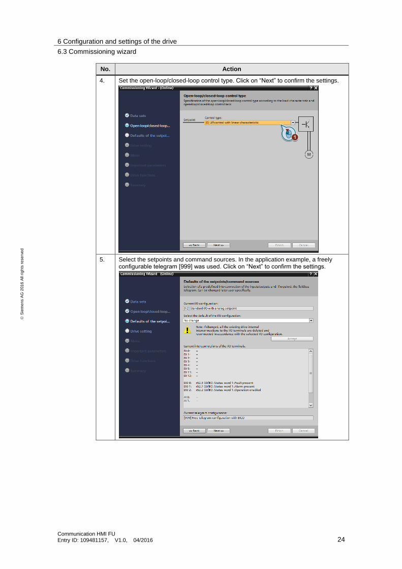
No. Action
4. Set the open-loop/closed-loop control type. Click on “Next” to confirm the settings.
5. Select the setpoints and command sources. In the application example, a freely configurable telegram [999] was used. Click on “Next” to confirm the settings.
6 Configuration and settings of the drive
6.3 Commissioning wizard
Communication HMI FU Entry ID: 109481157, V1.0, 04/2016 25
S
iem
en
s A
G 2
01
6 A
ll ri
gh
ts r
ese
rve
d
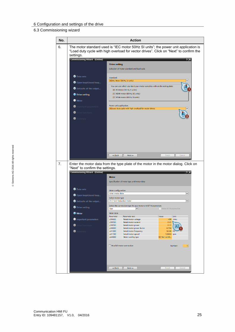
No. Action
6. The motor standard used is “IEC motor 50Hz SI units”; the power unit application is “Load duty cycle with high overload for vector drives”. Click on “Next” to confirm the settings.
7. Enter the motor data from the type plate of the motor in the motor dialog. Click on “Next” to confirm the settings.
6 Configuration and settings of the drive
6.3 Commissioning wizard
Communication HMI FU Entry ID: 109481157, V1.0, 04/2016 26
S
iem
en
s A
G 2
01
6 A
ll ri
gh
ts r
ese
rve
d
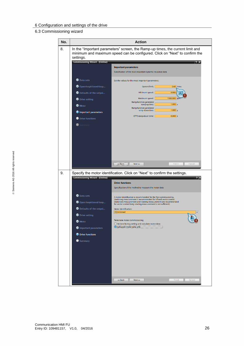
No. Action
8. In the “Important parameters” screen, the Ramp-up times, the current limit and minimum and maximum speed can be configured. Click on “Next” to confirm the settings.
9. Specify the motor identification. Click on “Next” to confirm the settings.

6 Configuration and settings of the drive
6.3 Commissioning wizard
Communication HMI FU Entry ID: 109481157, V1.0, 04/2016 27
S
iem
en
s A
G 2
01
6 A
ll ri
gh
ts r
ese
rve
d
No. Action
10. Confirm your settings with the summary and the Finish button.
6 Configuration and settings of the drive
6.4 Parameterizing converter settings
Communication HMI FU Entry ID: 109481157, V1.0, 04/2016 28
S
iem
en
s A
G 2
01
6 A
ll ri
gh
ts r
ese
rve
d
6.4 Parameterizing converter settings
To modify converter settings, proceed as follows:
Table 6-4
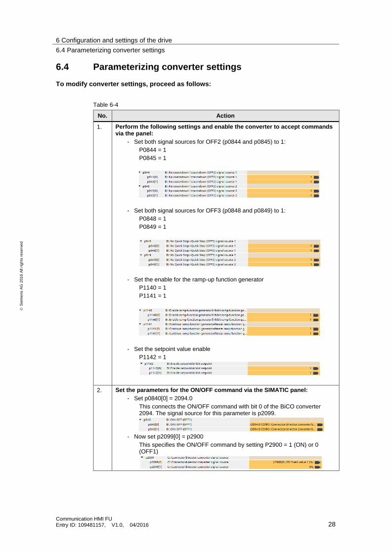
No. Action
1. Perform the following settings and enable the converter to accept commands via the panel:
- Set both signal sources for OFF2 (p0844 and p0845) to 1:
P0844 = 1
P0845 = 1
- Set both signal sources for OFF3 (p0848 and p0849) to 1:
P0848 = 1
P0849 = 1
- Set the enable for the ramp-up function generator
P1140 = 1
P1141 = 1
- Set the setpoint value enable
P1142 = 1
2. Set the parameters for the ON/OFF command via the SIMATIC panel:
- Set p0840[0] = 2094.0
This connects the ON/OFF command with bit 0 of the BiCO converter 2094. The signal source for this parameter is p2099.
- Now set p2099[0] = p2900
This specifies the ON/OFF command by setting P2900 = 1 (ON) or 0 (OFF1)

6 Configuration and settings of the drive
6.4 Parameterizing converter settings
Communication HMI FU Entry ID: 109481157, V1.0, 04/2016 29
S
iem
en
s A
G 2
01
6 A
ll ri
gh
ts r
ese
rve
d
No. Action
3. Define the parameters for the setpoint specification
- Set
- P1016 = 1 (Fixed speed setpoint select mode)
- - P1070 = 1001 (Fixed speed setpoint 1)
- - P1020 = 1 (Fixed speed setpoint selection Bit 0)
-
7 Operating the Application
7.1 Commissioning the example project
Communication HMI FU Entry ID: 109481157, V1.0, 04/2016 30
S
iem
en
s A
G 2
01
6 A
ll ri
gh
ts r
ese
rve
d
7 Operating the Application
Before you start the configuration, check the wiring of the components.
7.1 Commissioning the example project
Table 7-1
No. Action
1. Unzip “109481157_HMI_FU_CODE_v13.zip”
2. Start the TIA Portal.
3. Unzip the project “FrequencyConverter.zap13”.
4. Load the SIMATIC WinCC project to the Comfort Panel.
5. Load the SIMATIC Startdrive project to the frequency converter.
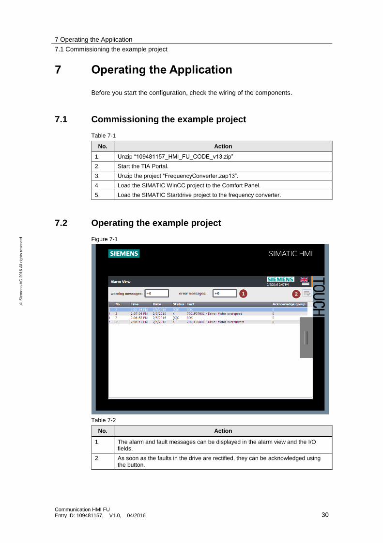
7.2 Operating the example project
Figure 7-1
Table 7-2
No. Action
1. The alarm and fault messages can be displayed in the alarm view and the I/O fields.
2. As soon as the faults in the drive are rectified, they can be acknowledged using the button.
1 2
7 Operating the Application
7.2 Operating the example project
Communication HMI FU Entry ID: 109481157, V1.0, 04/2016 31
S
iem
en
s A
G 2
01
6 A
ll ri
gh
ts r
ese
rve
d
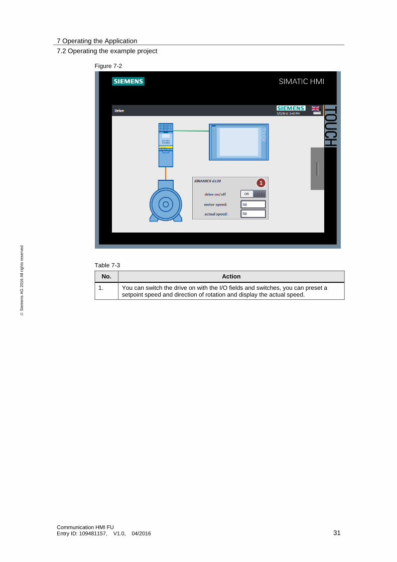
Figure 7-2
Table 7-3
No. Action
1. You can switch the drive on with the I/O fields and switches, you can preset a setpoint speed and direction of rotation and display the actual speed.
1
8 Further Notes, Tips & Tricks, etc.
Communication HMI FU Entry ID: 109481157, V1.0, 04/2016 32
S
iem
en
s A
G 2
01
6 A
ll ri
gh
ts r
ese
rve
d
8 Further Notes, Tips & Tricks, etc.
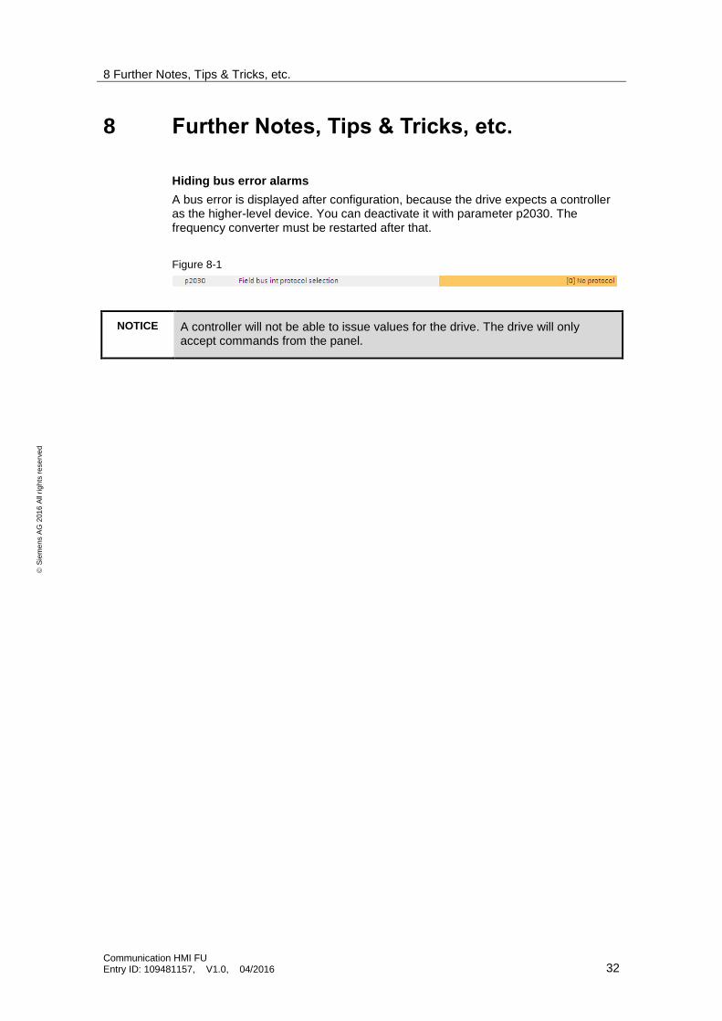
Hiding bus error alarms
A bus error is displayed after configuration, because the drive expects a controller as the higher-level device. You can deactivate it with parameter p2030. The frequency converter must be restarted after that.
Figure 8-1
NOTICE A controller will not be able to issue values for the drive. The drive will only accept commands from the panel.
9 Alternative
Communication HMI FU Entry ID: 109481157, V1.0, 04/2016 33
S
iem
en
s A
G 2
01
6 A
ll ri
gh
ts r
ese
rve
d
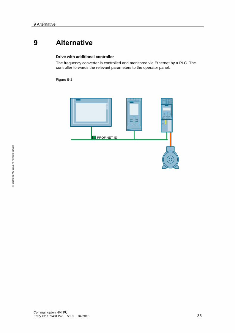
9 Alternative
Drive with additional controller
The frequency converter is controlled and monitored via Ethernet by a PLC. The controller forwards the relevant parameters to the operator panel.
Figure 9-1
PROFINET IE
10 Links & Literature
Communication HMI FU Entry ID: 109481157, V1.0, 04/2016 34
S
iem
en
s A
G 2
01
6 A
ll ri
gh
ts r
ese
rve
d
10 Links & Literature Table 10-1
Topic Title
\1\ Siemens Industry Online Support
http://support.industry.siemens.com
\2\ Download page of the entry
https://support.industry.siemens.com/cs/ww/en/view/109481157
11 History
Table 11-1
Version Date Modifications
V1.0 04/2016 First version